Psion WLPC24H User Manual 80440 4 base

Psion Inc 80440 4 base

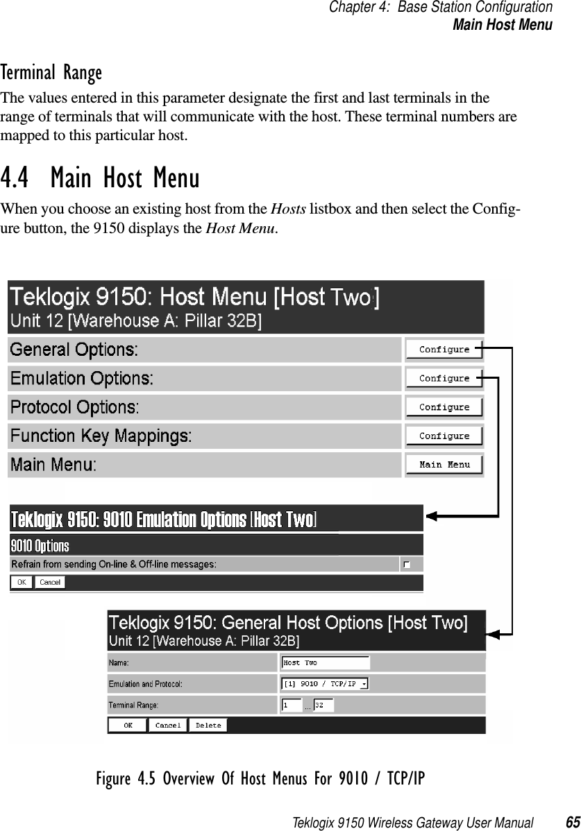
Teklogix 9150 Wireless Gateway User Manual Chapter 4 Base Station Configuration
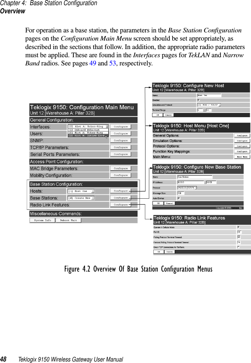
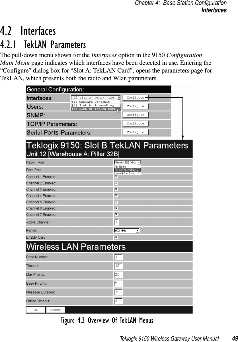
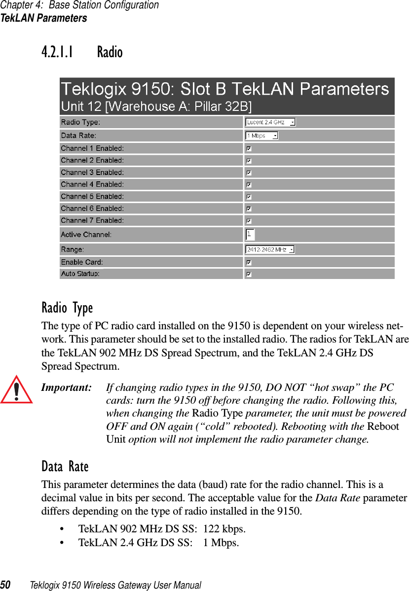
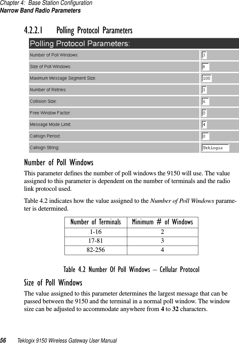
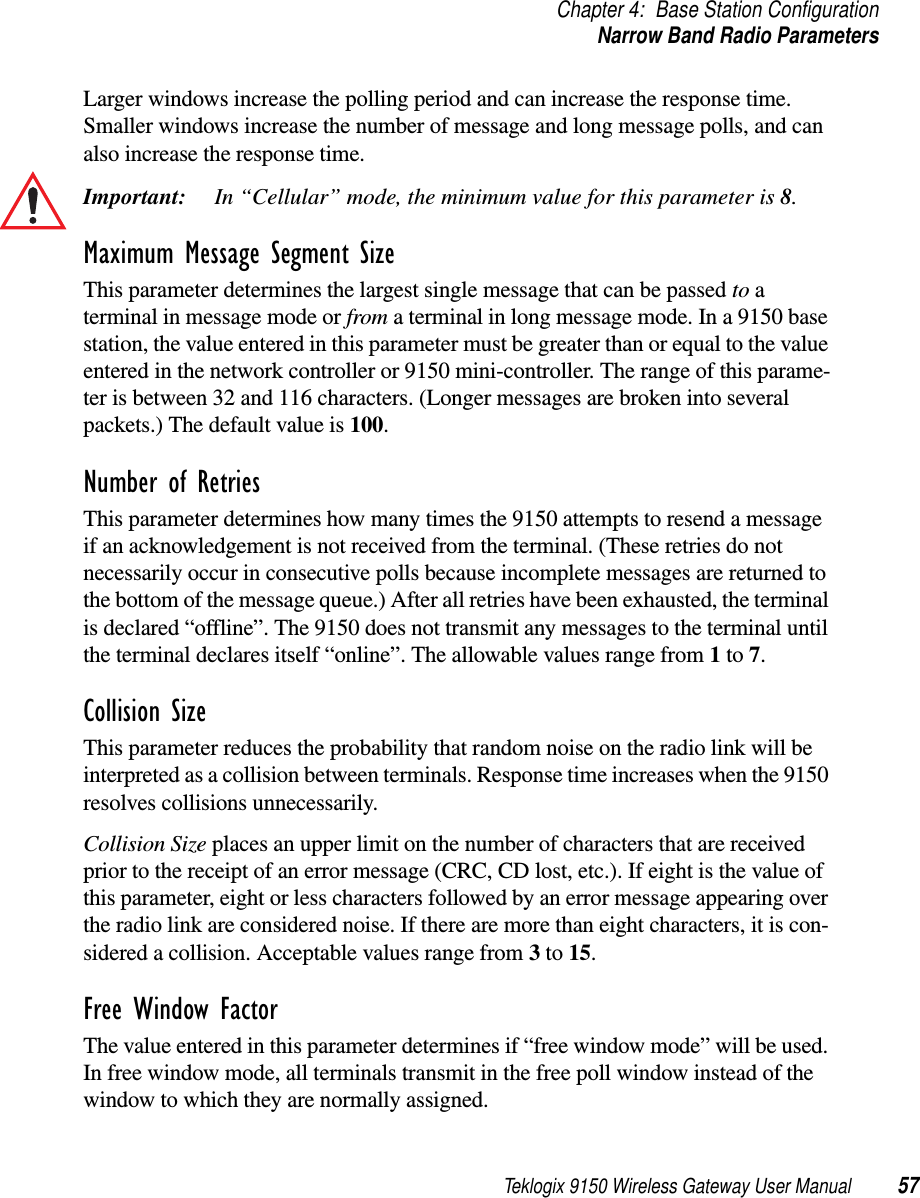
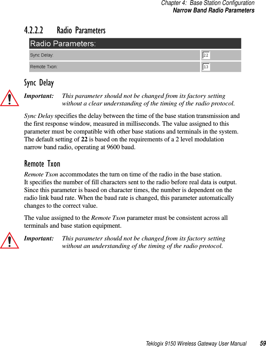
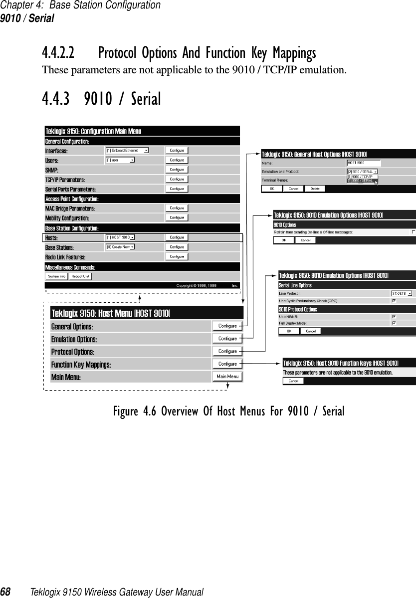
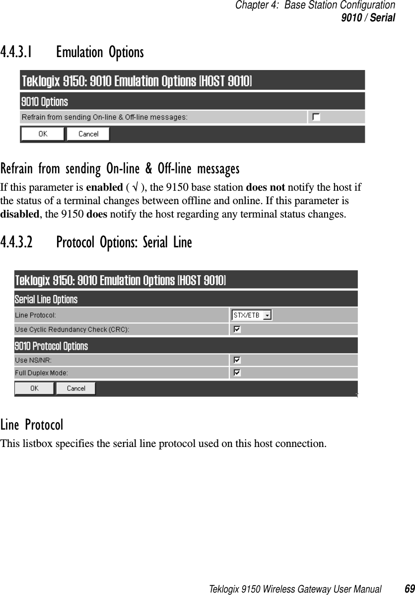
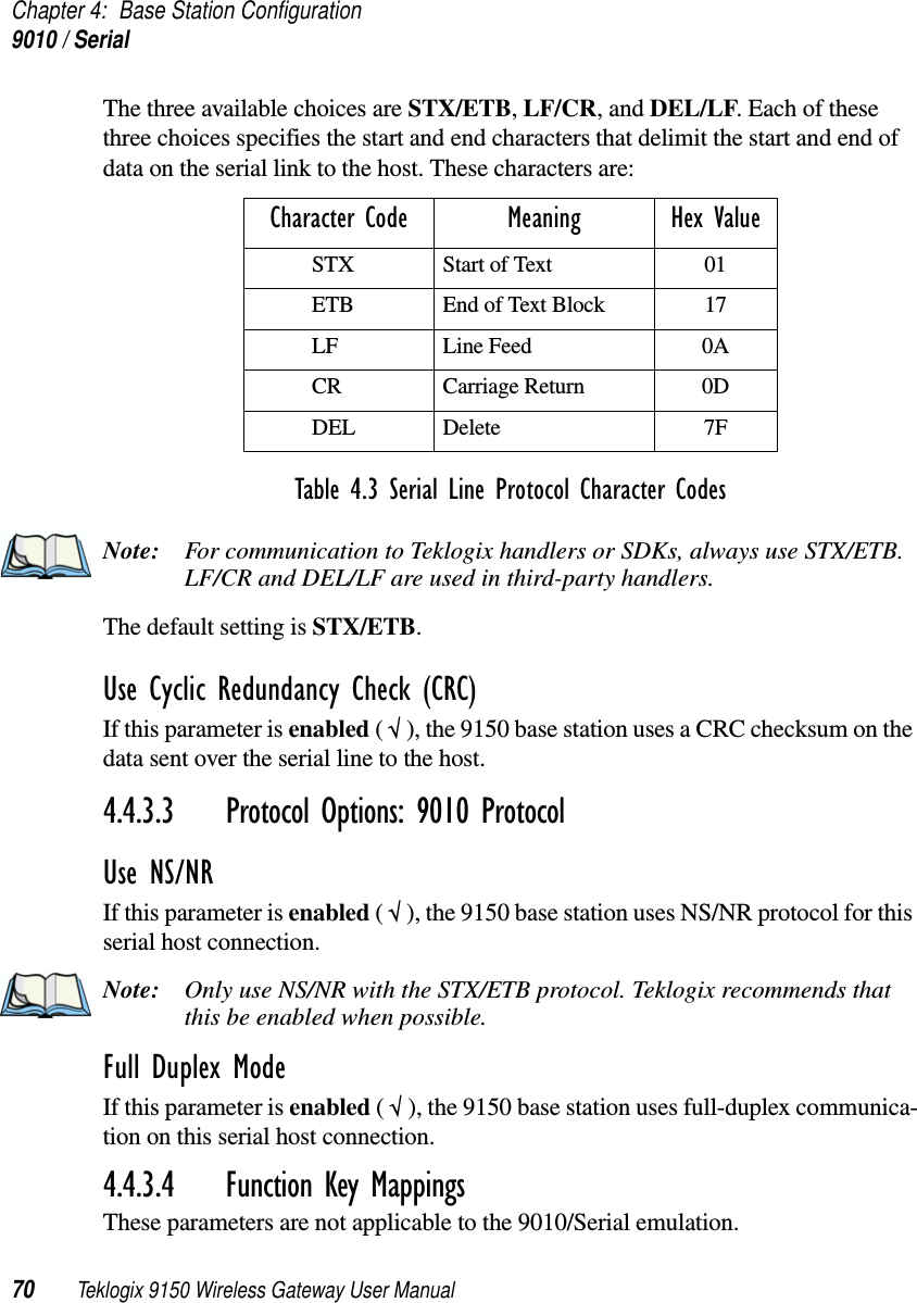
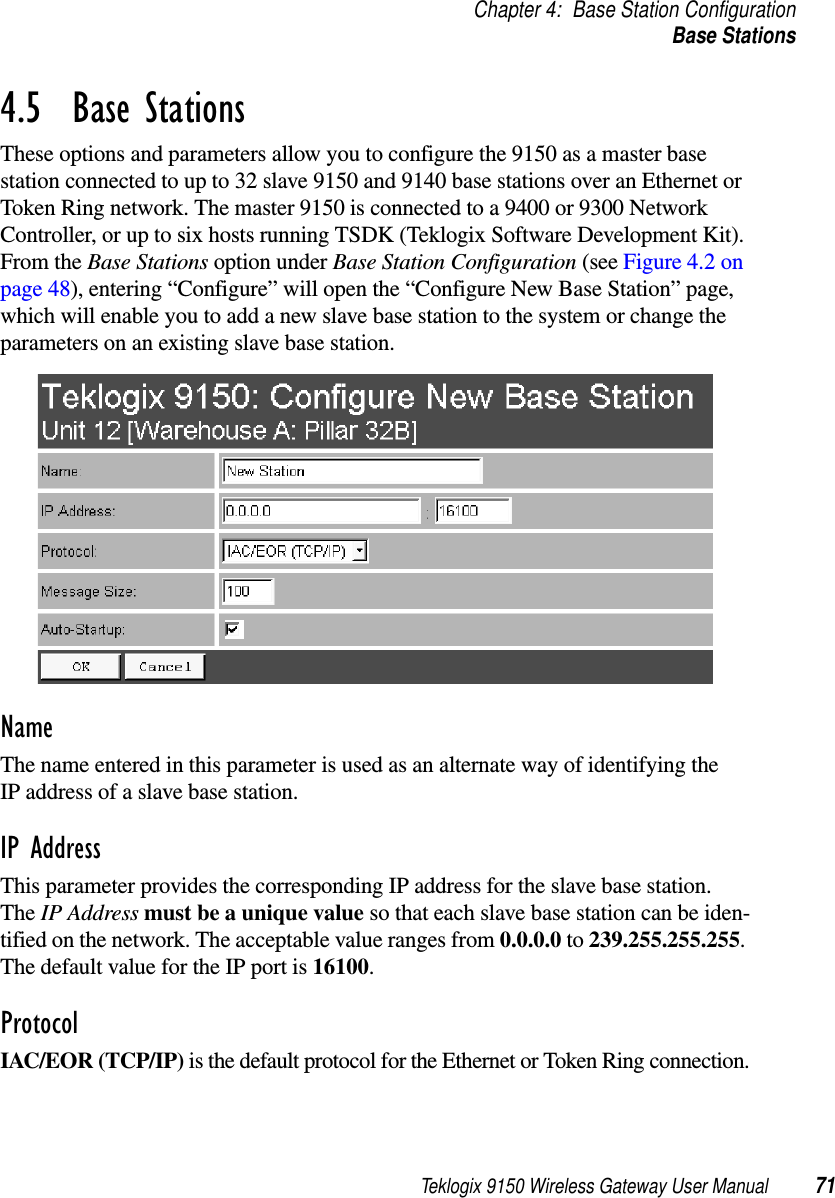
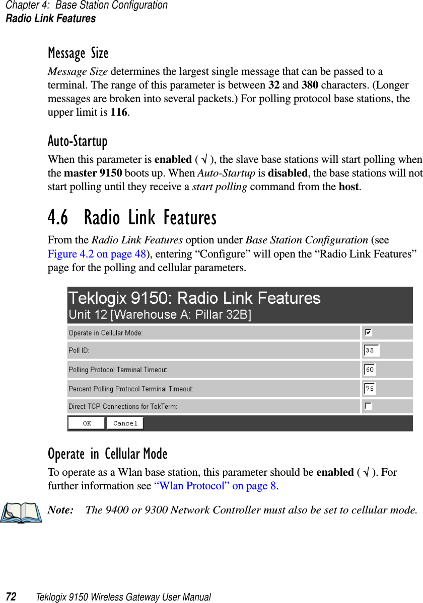
Teklogix 9150 Wireless Gateway User Manual 45BASE STATION CONFIGURATION 44.1  Overview................................474.2  Interfaces................................494.2.1  TekLAN Parameters....................494.2.1.1  Radio.........................504.2.1.2  Wireless LAN Parameters..............524.2.2  Narrow Band Radio Parameters . . . . . . . . . . . . . .534.2.2.1  Polling Protocol Parameters . . . . . . . . . . . . .564.2.2.2  Radio Parameters . . . . . . . . . . . . . . . . . .594.2.2.3  Radio Channels . . . . . . . . . . . . . . . . . . .604.2.2.4  TRX7370 Radio Card Parameters . . . . . . . . . .604.3  Hosts..................................634.4  Main Host Menu............................654.4.1  General Host Options...................664.4.2  9010 / TCP/IP . . . . . . . . . . . . . . . . . . . . . . .674.4.2.1  Emulation Options. . . . . . . . . . . . . . . . . .674.4.2.2  Protocol Options And Function Key Mappings . . .684.4.3  9010 / Serial . . . . . . . . . . . . . . . . . . . . . . . .684.4.3.1  Emulation Options. . . . . . . . . . . . . . . . . .694.4.3.2  Protocol Options: Serial Line . . . . . . . . . . . .694.4.3.3  Protocol Options: 9010 Protocol . . . . . . . . . .704.4.3.4  Function Key Mappings . . . . . . . . . . . . . . .704.5  Base Stations..............................714.6  Radio Link Features..........................72
Teklogix 9150 Wireless Gateway User Manual 47Chapter 4: Base Station ConfigurationOverview4.1  OverviewThe 9150 Wireless Gateway can operate as a base station, facilitating communica-tions between terminals and wireless base stations and a Teklogix 9400 or 9300 Network Controller, or 9140 Wireless Gateway (as a mini-controller) with a range of host platforms. Alternatively, the network controller can be a host running a Teklogix SDK (handler). The 9150 can also act as a slave base station to a 9140 on the network. As a base station, the 9150 uses the Wireless LAN (Wlan) or Adaptive Polling/Contention RF protocols. Note: The 9150 main parameters should first be set up as described in Chapter 3: “9150 Main Configuration”  For details on the RF protocols, see page 8.Figure 4.1 9150 Base Station Configuration9150ETHERNETTCP/IP915091408055 Vehicle-Mount94007030 Hand-HeldSERIALWireless GatewayNetwork ControllerWireless GatewayRF TerminalRF TerminalWireless GatewayHOST
Chapter 4: Base Station ConfigurationOverview48 Teklogix 9150 Wireless Gateway User ManualFor operation as a base station, the parameters in the Base Station Configuration pages on the Configuration Main Menu screen should be set appropriately, as described in the sections that follow. In addition, the appropriate radio parameters must be applied. These are found in the Interfaces pages for TekLAN and Narrow Band radios. See pages 49 and 53, respectively. Figure 4.2 Overview Of Base Station Configuration Menus
Teklogix 9150 Wireless Gateway User Manual 49Chapter 4: Base Station ConfigurationInterfaces4.2  Interfaces4.2.1  TekLAN ParametersThe pull-down menu shown for the Interfaces option in the 9150 Configuration Main Menu page indicates which interfaces have been detected in use. Entering the “Configure” dialog box for “Slot A: TekLAN Card”, opens the parameters page for TekLAN, which presents both the radio and Wlan parameters.Figure 4.3 Overview Of TekLAN Menus
Chapter 4: Base Station ConfigurationTekLAN Parameters50 Teklogix 9150 Wireless Gateway User Manual4.2.1.1 RadioRadio TypeThe type of PC radio card installed on the 9150 is dependent on your wireless net-work. This parameter should be set to the installed radio. The radios for TekLAN are the TekLAN 902 MHz DS Spread Spectrum, and the TekLAN 2.4 GHz DS Spread Spectrum.Important: If changing radio types in the 9150, DO NOT “hot swap” the PC cards: turn the 9150 off before changing the radio. Following this, when changing the Radio Type parameter, the unit must be powered OFF and ON again (“cold” rebooted). Rebooting with the Reboot Unit option will not implement the radio parameter change.Data RateThis parameter determines the data (baud) rate for the radio channel. This is a decimal value in bits per second. The acceptable value for the Data Rate parameter differs depending on the type of radio installed in the 9150. •TekLAN 902 MHz DS SS: 122 kbps.•TekLAN 2.4 GHz DS SS: 1 Mbps.
Teklogix 9150 Wireless Gateway User Manual 51Chapter 4: Base Station ConfigurationTekLAN ParametersChannel n EnabledThese parameters are used to enable ( √ ) or disable a channel. The number of chan-nels available is determined by the type of radio installed. See “PC Card Radios” on page 145 for the number of available channels for each radio type.Active ChannelThis parameter determines the current default radio channel.Range The federal agencies, Industry Canada and the Federal Communications Commis-sion in the United States, as well as other country-specific agencies world-wide, regulate the use of radio frequencies to ensure that communication conflicts are avoided. See “PC Card Radios” on page 145 for the assigned frequencies for each radio type.The Range parameter determines which channels can be enabled and is set accord-ing to the approved frequency range in the country where the system is installed. The TekLAN 902 MHz radio is only assigned the 902 MHz frequency. For the TekLAN 2.4 GHz radio, the frequency range and the associated channels and countries are assigned as follows:Table 4.1 Frequency Range – TekLAN 2.4 GHz Spread Spectrum (TRX7425)Enable CardThis parameter enables the PC card ( √ ). The card may be disabled temporarily when, for testing purposes, it is required that there be no radio interference.Auto StartupThis parameter enables ( √ ) polling immediately when the 9150 is rebooted. If Auto Startup is disabled, the 9150 will wait until polling is initialized from the network controller. When the 9150 is operating as a Wlan base station under a network con-troller, this parameter should be disabled.Country Range Channels AvailableFor testing purposes only. 2412-2462 1 to 6Canada, U.S., U.K. 2422-2462 2 to 6Australia 2422-2442 2 to 4
Chapter 4: Base Station ConfigurationTekLAN Parameters52 Teklogix 9150 Wireless Gateway User Manual4.2.1.2 Wireless LAN ParametersThe Wlan protocol can only be used with spread spectrum radios.Important: If your system is using the Wlan protocol, make sure that Operate in Cellular Mode is enabled (see page 72) in the Radio Link Features sub-menu and that cellular mode is also set on the 9400/9300 Network Controller.Base NumberThis parameter is used to assign a unique address to each base station. As the termi-nals move from one base station to another, this address is transmitted by the base stations to the terminals, identifying each 9150 on a multiple base station system. The allowable range of base station numbers is 1 to 64.TimeoutThis value is used to adjust Wlan performance and should be set to 10.Max PriorityThis value is used to adjust Wlan performance and should be set to 20.
Teklogix 9150 Wireless Gateway User Manual 53Chapter 4: Base Station ConfigurationNarrow Band Radio ParametersBase Priority (TekLAN 2.4 GHz)The Base Priority parameter determines the number of priority transmit slots reserved for each base station. The allowable range for this parameter is 0 to 100. For optimal performance, this parameter should be set to a value of 2.Message Duration (TekLAN 2.4 GHz)This parameter controls the duration of transmit slots to optimize communications and decrease the likelihood of collisions. A Message Duration value of 1 translates into a slot duration of 130 micro seconds. The allowable range for this parameter is 2 to 200. For optimal performance, this parameter should be set to 15.Offline TimeoutThis parameter determines the time in minutes that a terminal is allowed to be inac-tive before the 9150 declares it offline. An offline terminal is still considered part of the system. Messages to offline terminals are queued at the 9150. The terminal remains offline until it transmits any message. Values for this parameter range from 0 to 100. If the parameter is set to 0, terminals are never declared offline. 4.2.2  Narrow Band Radio ParametersThe pull-down menu shown for the Interfaces option on the 9150 Configuration Main Menu page indicates which interfaces have been detected in use. For the selec-tion “Slot A: Teklogix Narrowband”, entering the “Configure” dialog box will open the parameters pages for the TRX7370 Narrow Band PC card radio. These pages list the polling protocol and radio parameters, and show the radio card’s permanent communications settings.
Chapter 4: Base Station ConfigurationNarrow Band Radio Parameters54 Teklogix 9150 Wireless Gateway User ManualFigure 4.4 Overview Of Teklogix Narrow Band Menus
Teklogix 9150 Wireless Gateway User Manual 55Chapter 4: Base Station ConfigurationNarrow Band Radio ParametersEnable CardThis parameter enables the PC card ( √ ). The card may be disabled temporarily when, for testing purposes, it is required that there be no radio interference.Important: If changing radio types in the 9150, DO NOT “hot swap” the PC cards: turn the 9150 off before changing the radio. Auto-StartupThis parameter enables ( √ ) polling immediately when the 9150 is rebooted. If Auto Startup is disabled, the 9150 will wait until polling is initialized from the network controller. Shared ChannelShared Channel is only used in Holland to accommodate government requirements. When enabled ( √ ), it imposes timing restrictions for polling. Every 2 seconds of polling is followed by 0.5 seconds of silence—no polling occurs. Further, if another carrier is detected on the channel, the 9150 will cease radio trans-missions on that channel until the path is clear.
Chapter 4: Base Station ConfigurationNarrow Band Radio Parameters56 Teklogix 9150 Wireless Gateway User Manual4.2.2.1 Polling Protocol ParametersNumber of Poll WindowsThis parameter defines the number of poll windows the 9150 will use. The value assigned to this parameter is dependent on the number of terminals and the radio link protocol used.Table 4.2 indicates how the value assigned to the Number of Poll Windows parame-ter is determined.Table 4.2 Number Of Poll Windows – Cellular ProtocolSize of Poll WindowsThe value assigned to this parameter determines the largest message that can be passed between the 9150 and the terminal in a normal poll window. The window size can be adjusted to accommodate anywhere from 4 to 32 characters.Number of Terminals Minimum # of Windows1-16 217-81 382-256 4
Teklogix 9150 Wireless Gateway User Manual 57Chapter 4: Base Station ConfigurationNarrow Band Radio ParametersLarger windows increase the polling period and can increase the response time. Smaller windows increase the number of message and long message polls, and can also increase the response time. Important: In “Cellular” mode, the minimum value for this parameter is 8.Maximum Message Segment SizeThis parameter determines the largest single message that can be passed to a terminal in message mode or from a terminal in long message mode. In a 9150 base station, the value entered in this parameter must be greater than or equal to the value entered in the network controller or 9150 mini-controller. The range of this parame-ter is between 32 and 116 characters. (Longer messages are broken into several packets.) The default value is 100.Number of RetriesThis parameter determines how many times the 9150 attempts to resend a message if an acknowledgement is not received from the terminal. (These retries do not necessarily occur in consecutive polls because incomplete messages are returned to the bottom of the message queue.) After all retries have been exhausted, the terminal is declared “offline”. The 9150 does not transmit any messages to the terminal until the terminal declares itself “online”. The allowable values range from 1 to 7.Collision SizeThis parameter reduces the probability that random noise on the radio link will be interpreted as a collision between terminals. Response time increases when the 9150 resolves collisions unnecessarily.Collision Size places an upper limit on the number of characters that are received prior to the receipt of an error message (CRC, CD lost, etc.). If eight is the value of this parameter, eight or less characters followed by an error message appearing over the radio link are considered noise. If there are more than eight characters, it is con-sidered a collision. Acceptable values range from 3 to 15.Free Window FactorThe value entered in this parameter determines if “free window mode” will be used. In free window mode, all terminals transmit in the free poll window instead of the window to which they are normally assigned.
Chapter 4: Base Station ConfigurationNarrow Band Radio Parameters58 Teklogix 9150 Wireless Gateway User ManualEntering a value of 0 (zero) in this parameter disables free window mode. Increas-ing the value of this parameter increases the likelihood of a message being transmit-ted in the free window.Message Mode LimitThis parameter defines an upper limit to the number of messages that must be queued for transmission before message mode polling starts. Accepted values range from 0 to 7, where 0 disables message mode.Note: The number of terminals and past events are also part of the algorithm that determines whether or not to start message mode.Callsign PeriodA call sign is periodically transmitted as an audible Morse code signal. This parameter specifies the interval in minutes between call sign transmissions. Acceptable values range from 0 to 60. The federal agencies, Industry Canada and the Federal Communications Commission in the United States, require that each system transmit its own identification call sign every 15 minutes.In countries where a call sign is not required, setting this parameter to 0 prevents the transmission of any call signs, allowing for shorter poll time-outs in terminals and faster channel switching.Callsign StringThis string can be a maximum of 10 characters long. All characters are either numbers or letters. The prefix “DE” (from) is added to the beginning of the transmit-ted call sign.
Teklogix 9150 Wireless Gateway User Manual 59Chapter 4: Base Station ConfigurationNarrow Band Radio Parameters4.2.2.2 Radio ParametersSync DelayImportant: This parameter should not be changed from its factory setting without a clear understanding of the timing of the radio protocol.Sync Delay specifies the delay between the time of the base station transmission and the first response window, measured in milliseconds. The value assigned to this parameter must be compatible with other base stations and terminals in the system. The default setting of 22 is based on the requirements of a 2 level modulation narrow band radio, operating at 9600 baud.Remote TxonRemote Txon accommodates the turn on time of the radio in the base station.It specifies the number of fill characters sent to the radio before real data is output. Since this parameter is based on character times, the number is dependent on the radio link baud rate. When the baud rate is changed, this parameter automatically changes to the correct value.The value assigned to the Remote Txon parameter must be consistent across all terminals and base station equipment.Important: This parameter should not be changed from its factory setting without an understanding of the timing of the radio protocol.
Chapter 4: Base Station ConfigurationNarrow Band Radio Parameters60 Teklogix 9150 Wireless Gateway User Manual4.2.2.3 Radio ChannelsActive ChannelThis parameter determines the operating radio channel of the 9150. The channel selected must be an enabled channel. Refer to Enabled Channels, below, for details.Enabled ChannelsThis parameter is used to enable ( √ ) or disable up to 20 channels – the maximum number of channels supported by the TRX7370 radio. Enabling a channel allows the channel to be set to an operating channel (Active Channel) and also makes the channel available for channel searching. If, for example, the operating channel is 1 and all other channels are enabled, terminals may roam through all 20 channels. Note that the Enabled Channels menu only displays channels that have been config-ured with frequencies. See page 62 for the list of associated frequencies.4.2.2.4 TRX7370 Radio Card ParametersEntering the “Get Card Parameters” dialog box will open the list of General, Fre-quencies, and Tuning Values parameters for the TRX7370 Narrow Band PC card radio. These manufacturer’s settings are not configurable. The settings are shown on pages 62 and 63.
Teklogix 9150 Wireless Gateway User Manual 61Chapter 4: Base Station ConfigurationNarrow Band Radio Parameters
Chapter 4: Base Station ConfigurationNarrow Band Radio Parameters62 Teklogix 9150 Wireless Gateway User ManualGeneral ParametersFrequencies
Teklogix 9150 Wireless Gateway User Manual 63Chapter 4: Base Station ConfigurationHostsTuning Values4.3  HostsThe drop-down menu in this option shows the host names present on the system. Up to six hosts can be supported. A “host” must be configured for each master network controller, TSDK host, or master base station that communicates with the 9150. Opening the “Configure” dialog box for a selected host lists the parameters that can be modified or deleted for that host. New hosts can be added by selecting “[#] Create New” in the drop-down menu before entering the “Configure” dialog box.
Chapter 4: Base Station ConfigurationHosts64 Teklogix 9150 Wireless Gateway User ManualNameThis parameter indicates the assigned host name. The host name also appears on the RF terminal when switching between hosts in a multiple-host environment.Note: The name must not contain space characters.EnabledThe Enabled option must be turned on ( √ ) for terminals to communicate with this host.Emulation and ProtocolThis drop-down menu provides a list of host emulations and communication proto-cols supported by the 9150. The supported emulations with their respective protocols are: • 9010/ TCP/IP (See page 67 for configuration parameters).• 9010/ Serial (See pages 68 to 70 for configuration parameters).• 3274/Telnet (See pages 84 to 98 for Configuration Parameters).• 5250/Telnet (See pages 99 to 112 for Configuration Parameters).• ANSI/Telnet (See pages 113 to 121 for Configuration Parameters). When the 9150 acts as a base station, it uses the 9010 protocol (a proprietary protocol developed by Teklogix) with either a TCP/IP or serial connection to com-municate with a 9400 or 9300 Network Controller, or a host using a Teklogix Software Development Kit (TSDK). This protocol uses TESS (Teklogix Screen Subsystem) or ANSI data streams to communicate with terminals. For detailed information, please refer to the appropriate Teklogix User Manual for: 9400 or 9300 Network Controller, TSDK, TESS or ANSI.When the 9150 acts as a mini-controller, it uses the 3274 and 5250 emulation protocols to communicate with IBM hosts, or the ANSI emulation protocol to com-municate with ANSI hosts. For detailed information on configuring the 9150 as a mini-controller, please refer to Chapter 5: “Mini-Controller Configuration”.Protocols are the methods by which terminals communicate with host computers over various physical media such as Ethernet, Token Ring, and serial connections, as well as radio-link connections. The 9150 supports the TCP/IP protocol.
Teklogix 9150 Wireless Gateway User Manual 65Chapter 4: Base Station ConfigurationMain Host MenuTerminal RangeThe values entered in this parameter designate the first and last terminals in the range of terminals that will communicate with the host. These terminal numbers are mapped to this particular host.4.4  Main Host MenuWhen you choose an existing host from the Hosts listbox and then select the Config-ure button, the 9150 displays the Host Menu. Figure 4.5 Overview Of Host Menus For 9010 / TCP/IP
Chapter 4: Base Station ConfigurationGeneral Host Options66 Teklogix 9150 Wireless Gateway User ManualThe Host Menu has four configuration sub-menus:“General Host Options”When you select this sub-menu, the 9150 displays the General Options page for the host.“Emulation Options”When you select this sub-menu, the 9150 displays the Emulation Options page for the host. This page may vary depending on the type of emulation and protocol selected for the host.“Protocol Options” (not applicable to 9010/TCP/IP emulation)When you select this sub-menu, the 9150 displays the Protocol Options page for the host. This page may vary depending on the type of emulation and pro-tocol selected for the host.“Function Key Mappings” (3274, 5250, ANSI emulations only)When you select this sub-menu, the 9150 displays the Function Key Mapping page for the host. This page may vary depending on the type of emulation and protocol selected for the host.There is also a Main Menu button. When you select this button, the 9150 displays the Configuration Main Menu (see page 48).4.4.1  General Host OptionsIn this screen, you can select general options for the host connection. The host con-nection may also be deleted. Name This parameter allows you to enter a name for the new host.
Teklogix 9150 Wireless Gateway User Manual 67Chapter 4: Base Station Configuration9010 / TCP/IPEmulation and Protocol This parameter allows you to select the emulation and protocol to be used for the connection to this host. As a base station, the 9150 can use either 9010/ TCP/IP or 9010/SERIAL, depending on the connection to the network controller or host.Terminal Range This parameter allows you to specify the range of terminals which will communi-cate with this host. The left-hand textbox contains the lowest terminal number which is allowed to communicate with the host; the right-hand textbox contains the highest terminal number. Terminal numbers may range from 1 to 3840.4.4.2  9010 / TCP/IP4.4.2.1 Emulation Options Refrain from sending On-line & Off-line messagesIf this parameter is enabled ( √ ), the 9150 base station does not notify the host if the status of a terminal changes between offline and online. If this parameter is disabled, the 9150 does notify the host regarding any terminal status changes.
Chapter 4: Base Station Configuration9010 / Serial68 Teklogix 9150 Wireless Gateway User Manual4.4.2.2 Protocol Options And Function Key MappingsThese parameters are not applicable to the 9010 / TCP/IP emulation.4.4.3  9010 / SerialFigure 4.6 Overview Of Host Menus For 9010 / Serial
Teklogix 9150 Wireless Gateway User Manual 69Chapter 4: Base Station Configuration9010 / Serial4.4.3.1 Emulation Options Refrain from sending On-line & Off-line messagesIf this parameter is enabled ( √ ), the 9150 base station does not notify the host if the status of a terminal changes between offline and online. If this parameter is disabled, the 9150 does notify the host regarding any terminal status changes.4.4.3.2 Protocol Options: Serial LineLine ProtocolThis listbox specifies the serial line protocol used on this host connection.
Chapter 4: Base Station Configuration9010 / Serial70 Teklogix 9150 Wireless Gateway User ManualThe three available choices are STX/ETB, LF/CR, and DEL/LF. Each of these three choices specifies the start and end characters that delimit the start and end of data on the serial link to the host. These characters are:Note: For communication to Teklogix handlers or SDKs, always use STX/ETB. LF/CR and DEL/LF are used in third-party handlers.The default setting is STX/ETB.Use Cyclic Redundancy Check (CRC)If this parameter is enabled ( √ ), the 9150 base station uses a CRC checksum on the data sent over the serial line to the host.4.4.3.3 Protocol Options: 9010 ProtocolUse NS/NRIf this parameter is enabled ( √ ), the 9150 base station uses NS/NR protocol for this serial host connection.Note: Only use NS/NR with the STX/ETB protocol. Teklogix recommends that this be enabled when possible.Full Duplex ModeIf this parameter is enabled ( √ ), the 9150 base station uses full-duplex communica-tion on this serial host connection.4.4.3.4 Function Key MappingsThese parameters are not applicable to the 9010/Serial emulation.Character Code Meaning Hex ValueSTX Start of Text 01ETB End of Text Block 17LF Line Feed 0ACR Carriage Return 0DDEL Delete 7FTable 4.3 Serial Line Protocol Character Codes
Teklogix 9150 Wireless Gateway User Manual 71Chapter 4: Base Station ConfigurationBase Stations4.5  Base StationsThese options and parameters allow you to configure the 9150 as a master base station connected to up to 32 slave 9150 and 9140 base stations over an Ethernet or Token Ring network. The master 9150 is connected to a 9400 or 9300 Network Controller, or up to six hosts running TSDK (Teklogix Software Development Kit). From the Base Stations option under Base Station Configuration (see Figure 4.2 on page 48), entering “Configure” will open the “Configure New Base Station” page, which will enable you to add a new slave base station to the system or change the parameters on an existing slave base station.NameThe name entered in this parameter is used as an alternate way of identifying the IP address of a slave base station.IP AddressThis parameter provides the corresponding IP address for the slave base station. The IP Address must be a unique value so that each slave base station can be iden-tified on the network. The acceptable value ranges from 0.0.0.0 to 239.255.255.255. The default value for the IP port is 16100.ProtocolIAC/EOR (TCP/IP) is the default protocol for the Ethernet or Token Ring connection.
Chapter 4: Base Station ConfigurationRadio Link Features72 Teklogix 9150 Wireless Gateway User ManualMessage SizeMessage Size determines the largest single message that can be passed to a terminal. The range of this parameter is between 32 and 380 characters. (Longer messages are broken into several packets.) For polling protocol base stations, the upper limit is 116.Auto-StartupWhen this parameter is enabled ( √ ), the slave base stations will start polling when the master 9150 boots up. When Auto-Startup is disabled, the base stations will not start polling until they receive a start polling command from the host.4.6  Radio Link FeaturesFrom the Radio Link Features option under Base Station Configuration (see Figure 4.2 on page 48), entering “Configure” will open the “Radio Link Features” page for the polling and cellular parameters.Operate in Cellular ModeTo operate as a Wlan base station, this parameter should be enabled ( √ ). For further information see “Wlan Protocol” on page 8.Note: The 9400 or 9300 Network Controller must also be set to cellular mode.
Teklogix 9150 Wireless Gateway User Manual 73Chapter 4: Base Station ConfigurationRadio Link FeaturesPoll ID In Wlan protocol, this is a unique identifying number set only in a 9150 master base station, 9150 mini-controller or a network controller, which is used in the poll header when polling terminals. Poll ID is set by Teklogix personnel. In Adaptive Polling/Contention protocol for narrow band radios, Poll ID is used to assign a unique address to each base station. As the terminals move from one base station to another, this address is transmitted by the base stations to the terminals, identifying each 9150 in a multiple base station system.Polling Protocol Terminal Timeout This parameter determines the time in minutes that a terminal can be inactive before the 9150 declares it offline. Before this happens, the terminal will be declared offline by the Percent Polling Protocol Terminal Timeout parameter (see below). After the terminal is removed from the system, it will need to re-initialize in order to communicate with the 9150. This parameter reduces the overhead on the radio link caused when terminals which are not communicating are supported. The allowable values range from 1 to 240. Note: This parameter is not relevant for Wlan.Percent Polling Protocol Terminal Timeout This parameter determines the time that a terminal is allowed to be inactive before the 9150 declares it offline. This time is expressed as a percentage of the Polling Protocol Terminal Timeout parameter, above. For example, if the Polling Protocol Terminal Timeout is 60, and this parameter is set to 75%, then the timeout would be 60 min x 75% = 45 minutes. An offline terminal is still considered part of the system. Messages to offline terminals are queued at the 9150. The terminal remains offline until it transmits an online message. Values for this parameter range from 50 to 90.Direct TCP Connections for TekTermEnabling this parameter allows the TekTerm program resident in Teklogix terminals to connect directly to the 9150, when it is acting as a base station to a host via TCP/IP.

Navigation menu