Psion WLPC24H User Manual 80440 1 intro

Psion Inc 80440 1 intro

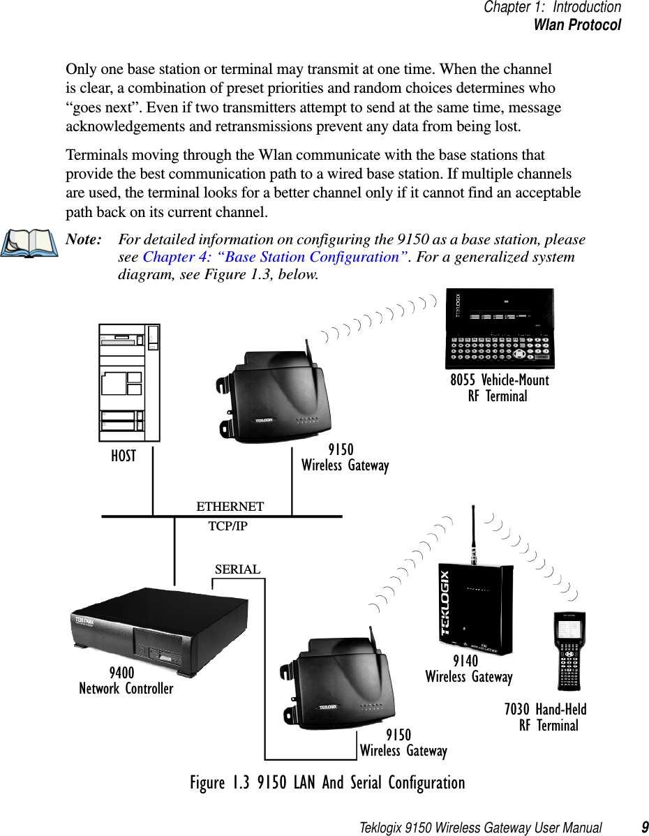
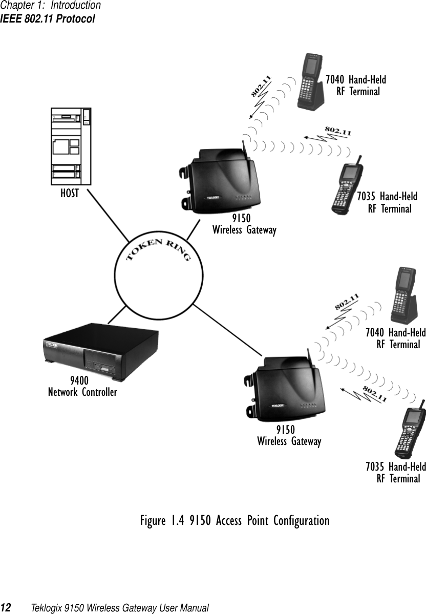
Teklogix 9150 Wireless Gateway User Manual Chapter 1 Introduction

Teklogix 9150 Wireless Gateway User Manual 1INTRODUCTION 11.1  About This Manual ........................31.2  Text Conventions..........................41.3  About The 9150 . .........................41.3.1  Base Station Functions.................61.3.2  Mini-Controller Functions...............61.3.3  Access Point Functions . . . . . . . . . . . . . . . .61.4  Radio Options...........................71.5  Radio Protocols..........................71.5.1  Adaptive Polling/Contention Protocol . . . . . . . . .81.5.2  Wlan Protocol.....................81.5.3  IEEE 802.11 Protocol . . . . . . . . . . . . . . . . 101.5.3.1  Inter-Access Point Protocol (IAPP) . . . . . . 11
Teklogix 9150 Wireless Gateway User Manual 3Chapter 1: IntroductionAbout This Manual1.1  About This ManualThis manual contains information about the installation, basic operation, and configuration of the 9150 Wireless Gateway. Chapter 1: Introductiondescribes the 9150 and the radio protocols it supports.Chapter 2: Installation Requirementsdescribes the physical installation of the Teklogix 9150 Wireless Gateway and how to connect to the 9150 for configuration and diagnostics.Chapter 3: 9150 Main Configurationdescribes the options available from the main configuration menus.Chapter 4: Base Station Configurationdescribes the configuration for a 9150 used as a base station linked to a network controller.Chapter 5: Mini-Controller Configurationdescribes the configuration for a 9150 used as a mini-controller.Chapter 6: Access Point Configurationdescribes the configuration for a 9150 used as an access point device between wired and wireless networks.Chapter 7: Specificationsoutlines the performance specifications for the 9150.Appendix A: Port Pinouts And Cable Diagramsincludes pinouts and diagrams of the ports and cables for the 9150.Appendix B: MAC Bridge Protocol Filters and OUIspresents tables of values for Ethernet II and DSAP/SSAP types, and OUI.
Chapter 1: IntroductionText Conventions4Teklogix 9150 Wireless Gateway User Manual1.2  Text ConventionsNote: Notes highlight additional helpful information.Important: These statements provide particularly important instructions or additional information that is critical to the operation of the computer and other equipment.Warning: These statements provide important information that may prevent injury, damage to the equipment, or loss of data.1.3  About The 9150The 9150 Wireless Gateway is designed to support a wide variety of system config-urations. Using the IEEE 802.11 Wireless LAN Standard, the 9150 is capable of operating as a transparent bridge (access point) between wireless and wired networks. This allows wireless clients to access the network and also move seamlessly between the 9150s in the network. The 9150 can also operate as a Teklogix base station or a mini-controller. The 9150 supports Type II PCMCIA cards so that multiple radio interfaces are pos-sible. The 9150 also has dual-radio functionality. It can support several combina-tions of radio types to function as both a mini-controller and base station, access point and base station, or access point and mini-controller. For details, see “Radio Options” on page 7. The 9150 Flash memory holds the boot code, configuration parameters and firm-ware. The 9150 Configuration program allows various parameter settings to be changed, added or deleted. The Flash can be reconfigured remotely via the network using a standard HTML Web Browser such as Netscape or MS Internet Explorer (for instructions, see Chapter 3: “9150 Main Configuration”).
Teklogix 9150 Wireless Gateway User Manual 5Chapter 1: IntroductionAbout The 9150Figure 1.1 The 9150 Wireless Gateway - Front ViewFigure 1.2 The 9150 Wireless Gateway - Bottom View
Chapter 1: IntroductionBase Station Functions6Teklogix 9150 Wireless Gateway User Manual1.3.1  Base Station FunctionsAs a base station, the 9150 provides a link between the local area network and the wireless network consisting of Teklogix mobile terminals, and base stations such as the 9140 Wireless Gateway. The 9150 and 9400/9300 Network Controller (or host using a Teklogix Software Development Kit) communicate using the 9010 propri-etary protocol with TCP/IP over Ethernet, Token Ring or serial connectivity. Wlan protocol enables the 9150 to communicate with 9140s without cable attachments (see Figure 4.1 on page 47). For information on configuring the 9150 as a base station, see Chapter 4: “Base Station Configuration”. For details on Wlan, see “Wlan Protocol” on page 8.1.3.2  Mini-Controller FunctionsThe 9150 is equipped with some emulation capabilities, allowing it to act as a mini-controller. When a 9150 is configured as a mini-controller, Teklogix terminals can emulate an ANSI, 5250 or 3274 terminal via a 9150 rather than through a 9400/9300 Network Controller.To configure the 9150 as a mini-controller, see Chapter 5: “Mini-Controller Config-uration”. For a generalized system diagram, see Figure 5.1 on page 78.1.3.3  Access Point FunctionsAs an access point, the 9150 Wireless Gateway forms a communication link between Teklogix RF terminals or wireless access point clients and a Teklogix Network Controller or a host computer. It communicates over an IEEE 802.11 RF data link with terminals and over a cable with a network controller or a host com-puter. The 9150 can be connected to the network through an Ethernet or Token Ring connection. The diagram in Figure 6.1 on page 125 illustrates a 9150 access point connection between a Teklogix 9400 Network Controller on Ethernet and IEEE 802.11 wireless devices. Figure 1.4 on page 12 shows a generalized Token Ring configuration.For information on the 9150 as an access point, see “IEEE 802.11 Protocol” on page 10 and Chapter 6: “Access Point Configuration”.
Teklogix 9150 Wireless Gateway User Manual 7Chapter 1: IntroductionRadio Options1.4  Radio OptionsThe 9150 supports Type II PCMCIA cards so that multiple radio interfaces are possible. There is one internal and one external PC card slot available. The type of PCMCIA radio card installed in the 9150 is dependent on your wireless network. Currently supported radios are: •TRX7370 Narrow Band DSP.•TekLAN 902 MHz DS Spread Spectrum (TRX7410).•TekLAN 2.4 GHz DS Spread Spectrum (TRX7425).•Proxim RangeLAN802 IEEE 802.11 FHSS 2.4 GHz (TRX7440).•Lucent WaveLAN IEEE 802.11 DSSS 2.4 GHz (TRX7430).The 9150 has dual-radio functionality. It can support several combinations of radio types to function as both a mini-controller and base station, access point and base sta-tion, or access point and mini-controller. The 902 MHz, 2.4 GHz (802.11 and TekLAN) and Narrow Band radios can be used in any combination, with the exception of dual TekLAN or dual Narrow Band radios.Important: The radio in the terminal must match the radio in the 9150 Wireless Gateway. If changing radio types in the 9150, DO NOT “hot swap” the PC cards: Turn the 9150 off before changing the radio.1.5  Radio ProtocolsRF protocols allow terminals to communicate with a base station by sharing the use of a radio channel in an efficient way. Teklogix systems use one of three types of RF protocols: the Teklogix Adaptive Polling/Contention protocol, the Teklogix Wireless LAN (Wlan) protocol, or the non-proprietary IEEE 802.11 protocol. When used as a base station, the 9150 uses either the Adaptive Polling/Contention protocol or the Wlan protocol. These two protocol types cannot be mixed on a single system. When used as an access point device, the 9150 employs the IEEE 802.11 protocol. These protocols are described in the following sections.
Chapter 1: IntroductionAdaptive Polling/Contention Protocol8Teklogix 9150 Wireless Gateway User Manual1.5.1  Adaptive Polling/Contention ProtocolThe Adaptive Polling/Contention protocol is always used on Narrow Band radio systems with baud rates of up to 19.2 kbps, and may also be used on Spread Spec-trum systems at higher rates.Terminals operating with this protocol do not transmit unless they receive polls from the 9150. Terminals are generally polled en masse. Following each poll, groups of terminals are assigned response windows in which they may respond to the poll. If a “collision” occurs – more than one terminal attempts to respond in a particular window – the 9150 that is polling divides and reassigns that group until the colliding terminals can respond without a collision.Adaptive features of this protocol allow the response windows to be adjusted to accommodate high or low RF traffic conditions, and to prevent data from being queued too long when a particular terminal has a burst of data to send or receive.Systems using adaptive polling/contention can use the cellular option so that terminal operators can roam the site, maintaining uninterrupted communication as they pass between coverage areas.If cellular base is not enabled, a “RESET: Press Enter” message appears on the terminal screen each time an operator moves from one base station coverage area to another. (Pressing <ENTER> restores communication, but some data may be lost.)1.5.2  Wlan ProtocolThe Wlan (Wireless LAN) protocol is used only on Spread Spectrum radio systems at baud rates of 122 kbps and higher. The Wlan protocol allows base stations to be added to a system without cable connections. A Wlan system consists of a minimum of one wired base station and zero or more wireless base stations. It can operate on either one channel – usually the case – or on multiple channels.When a Wlan system is operating, base stations do not send out polls. Instead, both wired and wireless base stations regularly broadcast routing information, indicating the available routes back to the controller. Both terminals and wireless base stations receive these broadcasts, determine the best communication route, and send their messages. If a better route becomes available, the terminal or wireless base will change communication paths.
Teklogix 9150 Wireless Gateway User Manual 9Chapter 1: IntroductionWlan ProtocolOnly one base station or terminal may transmit at one time. When the channel is clear, a combination of preset priorities and random choices determines who “goes next”. Even if two transmitters attempt to send at the same time, message acknowledgements and retransmissions prevent any data from being lost.Terminals moving through the Wlan communicate with the base stations that provide the best communication path to a wired base station. If multiple channels are used, the terminal looks for a better channel only if it cannot find an acceptable path back on its current channel.Note: For detailed information on configuring the 9150 as a base station, please see Chapter 4: “Base Station Configuration”. For a generalized system diagram, see Figure 1.3, below.Figure 1.3 9150 LAN And Serial Configuration9150ETHERNETTCP/IP915091408055 Vehicle-Mount94007030 Hand-HeldSERIALWireless GatewayNetwork ControllerWireless GatewayRF TerminalRF TerminalWireless GatewayHOST
Chapter 1: IntroductionIEEE 802.11 Protocol10 Teklogix 9150 Wireless Gateway User Manual1.5.3  IEEE 802.11 ProtocolThe IEEE 802.11 protocol is an OSI standard for Wireless Local Area Networks (WLANs). With this standard, any IEEE 802.11 radio can communicate with any other similarly-equipped device. However, IEEE 802.11 does not provide a standard for a total WLAN system. IEEE 802.11 solely standardizes two communications layers: Physical (PHY) and Medium Access Control (MAC). Three different PHY layer media are covered: 2.4 GHz Direct Sequence Spread Spectrum radio, 2.4 GHz Frequency Hopping Spread Spectrum radio, and infrared. Each station in a WLAN system has its own unique MAC address. Important: Equipment using one physical medium (e.g. Frequency Hopping versus Direct Sequence) will not interoperate with equipment using a different physical medium.IEEE 802.11 uses 2.4 GHz radios of relatively low power. The range is limited to no more than a hundred feet or so, depending on the conditions, and is usually restricted to “line of sight” operation. Therefore, most wireless networks need more than one coverage area, with terminals moving between the areas. To integrate those areas, systems using IEEE 802.11 protocol for their wireless networks require an IEEE 802.11-equipped bridge device (or access point), such as the 9150 Wireless Gateway. Using bridging software, the 9150 Wireless Gateway enables communication between any wireless IEEE 802.11-equipped stations and LAN stations operating on Ethernet or Token Ring. The 9150 itself is resident on the LAN and functions as a MAC bridge, providing transparent integration between the stations on the wire-less and wired networks. Each terminal is associated with one 9150. A frame from an RF terminal is sent to the 9150 that the terminal is associated with. The terminal puts a destination MAC address in the frame, which specifies a hardware address on the wired LAN side. Because the receiving 9150 is connected to an Ethernet or Token Ring network, it encapsulates the data in an Ethernet or Token Ring frame, respectively, including the destination MAC address specified by the terminal. The 9150 then sends the frame onto the physical network; the frame is picked up by whichever device is at the des-tination hardware address.
Teklogix 9150 Wireless Gateway User Manual 11Chapter 1: IntroductionIEEE 802.11 ProtocolWhen sending frames from the LAN side, the sending device puts the MAC address of the terminal in the frame header. Whichever 9150 has that terminal associated with it, takes the frame and passes it over the RF to the terminal. By passing frames in this way, the 9150 is acting as a MAC bridge. 1.5.3.1 Inter-Access Point Protocol (IAPP)The Inter-Access Point Protocol (IAPP) is an extension to the IEEE 802.11 protocol. IAPP facilitates roaming of mobile stations across different Basic Service Sets (groups of stations and their access points), and specifies how access points commu-nicate with each other. In a multiple-9150 system, IAPP informs the other 9150 Wireless Gateways when a new 9150 becomes active, and enables the awareness of the 9150s of each other. With IAPP, an IEEE 802.11 system can operate on one or more channels, with terminals moving between the 9150s. Although each terminal is associated with one 9150, it can reassociate with another 9150 to maintain uninterrupted communica-tions. The newly-associated 9150 will receive the terminal’s data frames and pass them onto the LAN. Returning frames are no longer accepted by the original 9150, which has disassociated from that terminal. The returning frames are now accepted by the newly-associated 9150 and passed over the RF to the terminal. Note: For detailed information on configuring the 9150 as an access point, please see Chapter 6: “Access Point Configuration”. For a generalized system diagram, see Figure 1.4 on page 12.
Chapter 1: IntroductionIEEE 802.11 Protocol12 Teklogix 9150 Wireless Gateway User ManualFigure 1.4 9150 Access Point Configuration9150915094007040 Hand-HeldWireless GatewayNetwork ControllerWireless GatewayRF TerminalHOST 7035 Hand-HeldRF Terminal7040 Hand-HeldRF Terminal7035 Hand-HeldRF Terminal

Navigation menu