Contents
- 1. TRX7431 User Manual
- 2. Teklogix 9150 Wireless Gateway User Manual
- 3. Teklogix 9150 Wireless Gateway User Manual Declaration of Conformity
- 4. Teklogix 9150 Wireless Gateway User Manual Cautions to Users
- 5. Teklogix 9150 Wireless Gateway User Manual Teklogix Offices
- 6. Teklogix 9150 Wireless Gateway User Manual Table of Contents
- 7. Teklogix 9150 Wireless Gateway User Manual Chapter 1 Introduction
- 8. Teklogix 9150 Wireless Gateway User Manual Chapter 2 Installation Requirements
- 9. Teklogix 9150 Wireless Gateway User Manual Chapter 3 9150 Main Configuration
- 10. Teklogix 9150 Wireless Gateway User Manual Chapter 4 Base Station Configuration
- 11. Teklogix 9150 Wireless Gateway User Manual Chapter 5 Mini Controller Configurati
- 12. Teklogix 9150 Wireless Gateway User Manual Chapter 6 Access Point Configuration
- 13. Teklogix 9150 Wireless Gateway User Manual Chapter 7 Specifications
- 14. Teklogix 9150 Wireless Gateway User Manual Appendix A
- 15. Teklogix 9150 Wireless Gateway User Manual Appendix B
- 16. Teklogix 9150 Wireless Gateway User Manual Index
- 17. Teklogix 9150 Wireless Gateway User Manual Appendix A
- 18. 7035 8255 8260 User Manual
- 19. 9150 User Manual
- 20. response to FCC correspondence 15472
9150 User Manual
9150
Wireless Gateway
User Manual
March 17, 2000 Part No. 80440.D
© Copyright 2000 by Teklogix Inc., Mississauga, Ontario
This document and the information it contains is the property of Teklogix Inc., is
issued in strict confidence, and is not to be reproduced or copied, in whole or in part,
except for the sole purpose of promoting the sale of Teklogix manufactured goods
and services. Furthermore, this document is not to be used as a basis for design, man-
ufacture, or sub-contract, or in any manner detrimental to the interests of
Teklogix Inc.
All trademarks are the property of their respective holders.
Return-To-Factory Warranty
Teklogix warrants a return-to-factory warranty for a period of 90 days from
shipment or 120 days from shipment where Teklogix installs the equipment. The
warranty on Teklogix manufactured equipment does not extend to any product that
has been tampered with, altered, or repaired by any person other than an employee
of an authorized Teklogix service organization. See Teklogix terms and conditions
of sale for full details.
Service
When requesting service, please provide information concerning the nature of the
failure and the manner in which the equipment was used when the failure occurred.
Type, model, and serial number should also be provided. Before returning any
products to the factory, call the Customer Services Group for a Return
Authorization number. This will help us to service your product more efficiently.
For a listing of worldwide offices, please refer to the last page of this manual.
Disclaimer
Every effort has been made to make this material complete, accurate, and up-to-
date. Teklogix Inc. reserves the right to make changes without notice and shall not
be responsible for any damages, including but not limited to consequential damages,
caused by reliance on the material presented, including but not limited to
typographical errors.

Declaration Of Conformity
Product: 9150 Wireless Gateway
Application of Council
Directives: EMC Directive: 89/336/EEC
Low Voltage Directive: 73/23/EEC
Conformity Declared
to Standards: EN 55022: 1994; Class B; ETS 300 328: 1996
EN 50082-1: 1997; ETS 300 683: 1997
EN 61000-4-2; ±4kV CD; ±8kV AD
EN 61000-4-3; 3V/m, 80-1000 MHz
EN 61000-4-4; ±1kV Signal lines; ±2kV Power lines
EN 61000-4-5; ±1kV Common; ±0.5kV Differential mode
EN 61000-4-6; 3VRMS, 150kHz-80 MHz
EN 61000-4-11; AC Mains Ports
EN 60950: 1992 + A1 + A2 + A3 + A4 + A11
Manufacturer: Teklogix Incorporated
2100 Meadowvale Blvd.
Mississauga, Ontario; Canada L5N 7J9
Year of Manufacture: 1998
Manufacturer’s Address
in the European
Community: Teklogix S.A.
Parc Club Du Golf - Bat 1.
13856 Aix-En-Provence
Cedex 3; France
Type of Equipment: Information Technology Equipment
Equipment Class: Commercial and Light Industrial


Teklogix 9150 Wireless Gateway User Manual i
TABLE OF CONTENTS
Caution To Users ...................................vii
Chapter 1: Introduction
1.1 About This Manual ............................3
1.2 Text Conventions.............................4
1.3 About The 9150 . .............................4
1.3.1 Base Station Functions .................... 6
1.3.2 Mini-Controller Functions................... 6
1.3.3 Access Point Functions .................... 6
1.4 Radio Options...............................7
1.5 Radio Protocols..............................7
1.5.1 Adaptive Polling/Contention Protocol.............8
1.5.2 Wlan Protocol.........................8
1.5.3 IEEE 802.11 Protocol .....................10
1.5.3.1 Inter-Access Point Protocol (IAPP)........11
Chapter 2: Installation Requirements
2.1 Choosing The Right Location.......................15
2.1.1 Environment..........................15
2.1.2 Maintenance..........................16
2.1.3 Power And Antenna Cables..................16
2.2 Connecting To External Devices .....................17
2.2.1 Ports..............................17
2.2.2 Status Indicators (LEDs) ...................18
2.2.3 Preparing For LAN Installation................18
2.2.3.1 Ethernet......................19
2.2.3.2 Token Ring ....................19
2.2.4 Preparing For Serial Installation................20
2.2.5 Connecting A Video Display Terminal . . ..........21
2.3 Changing The Configuration With A Web Browser...........21

Contents
ii Teklogix 9150 Wireless Gateway User Manual
Chapter 3: 9150 Main Configuration
3.1 Configuration Main Menu........................25
3.2 Configuring The IP Address....................... 25
3.3 Accessing The Menus . .........................27
3.4 General Configuration Options..................... 29
3.4.1 Interfaces...........................30
3.4.1.1 Onboard Ethernet ................30
3.4.1.2 Slot n: Token-Ring................32
3.4.1.3 Slot n: PC Card Radio..............34
3.4.2 Users.............................34
3.4.3 SNMP ............................35
3.4.3.1 System Parameters................36
3.4.3.2 SNMP Communities............... 36
3.4.3.3 Trap Receivers..................36
3.4.4 TCP/IP Parameters...................... 36
3.4.4.1 Host Table....................37
3.4.4.2 Bootp.......................38
3.4.4.3 DNS .......................39
3.4.5 Serial Ports Parameters.................... 40
3.4.5.1 Console Port...................40
3.4.5.2 Serial Port ....................40
3.5 Access Point/Base Station Configurations................41
3.6 Miscellaneous Commands........................42
3.6.1 System Info..........................42
3.6.2 Reboot Unit.......................... 43
Chapter 4: Base Station Configuration
4.1 Overview.................................47
4.2 Interfaces.................................49
4.2.1 TekLAN Parameters.....................49
4.2.1.1 Radio.......................50
4.2.1.2 Wireless LAN Parameters............52
4.2.2 Narrow Band Radio Parameters...............53
4.2.2.1 Polling Protocol Parameters...........56
4.2.2.2 Radio Parameters.................59
4.2.2.3 Radio Channels..................60
4.2.2.4 TRX7370 Radio Card Parameters . . ...... 60

Teklogix 9150 Wireless Gateway User Manual iii
Contents
4.3 Hosts....................................63
4.4 Main Host Menu .............................65
4.4.1 General Host Options.....................66
4.4.2 9010 / TCP/IP.........................67
4.4.2.1 Emulation Options ................67
4.4.2.2 Protocol Options And Function Key Mappings. .68
4.4.3 9010 / Serial..........................68
4.4.3.1 Emulation Options ................69
4.4.3.2 Protocol Options: Serial Line...........69
4.4.3.3 Protocol Options: 9010 Protocol.........70
4.4.3.4 Function Key Mappings..............70
4.5 Base Stations ...............................71
4.6 Radio Link Features............................72
Chapter 5: Mini-Controller Configuration
5.1 Overview.................................77
5.2 Hosts....................................80
5.3 Main Host Menu .............................82
5.3.1 General Options........................83
5.3.2 9010 Emulations........................84
5.3.3 3274/Telnet ..........................84
5.3.3.1 Emulation Options.................84
5.3.3.2 Protocol Options..................95
5.3.3.3 Function Key Mappings..............98
5.3.4 5250/Telnet ..........................99
5.3.4.1 Emulation Options.................99
5.3.4.2 Protocol Options.................110
5.3.4.3 Function Key Mappings.............112
5.3.5 ANSI/Telnet .........................113
5.3.5.1 Emulation Options................113
5.3.5.2 Protocol Options.................116
5.3.5.3 Function Key Mappings.............121
Chapter 6: Access Point Configuration
6.1 Overview................................125
6.2 Interfaces................................126
6.2.1 IEEE 802.11 (Frequency Hopping Radio Parameters) . . . 126

Contents
iv Teklogix 9150 Wireless Gateway User Manual
6.2.2 IEEE 802.11 (Direct Sequence Radio Parameters) .....128
6.3 MAC Bridge Parameters.........................129
6.3.1 General Configuration....................131
6.3.2 Address Filters: MAC Address................132
6.3.3 Protocol Filters........................133
6.3.3.1 Ethernet II Filters.................136
6.3.3.2 LLC Filters....................137
6.3.3.3 SNAP Filters...................138
6.3.3.4 Storm Detection.................139
6.4 Mobility Configuration .........................140
6.4.1 IAPP Parameters.......................142
Chapter 7: Specifications
7.1 Specifications For The 9150 Wireless Gateway . ............145
7.1.1 PC Card Radios .......................145
7.1.2 Power Requirements.....................146
7.1.3 Physical Description . . ...................146
7.1.4 Processor And Memory...................147
7.1.5 Environmental Requirements ................147
7.1.6 Network Interfaces......................147
7.1.7 SLIM Cards .........................147
7.1.8 Approvals...........................147
Appendices
Appendix A: Port Pinouts And Cable Diagrams
A.1 Console Port.............................. A-1
A.2 RS-232 Plus Port (SLIM Card) . . .................. A-1
A.3 RS-232/Current Loop Port (SLIM Card) ............... A-2
A.4 DA15 Connector Pinout (10Base5 Ethernet) . . ........... A-3
A.5 RJ-45 Connector Pinouts (10Base-T Ethernet) . ........... A-4
A.6 Token Ring Dsub9 Connector . . . .................. A-5
A.7 Serial Cable Descriptions....................... A-6
Appendix B: MAC Bridge Protocol Filters and OUIs
B.1 Ethernet II Types (RFC 1700) . . . .................. B-1

Teklogix 9150 Wireless Gateway User Manual v
Contents
B.1.1 Listing by Description ....................B-1
B.1.2 Listing By Type (Hexadecimal)...............B-8
B.2 DSAP/SSAP Types.......................... B-14
B.3 OUI Values.............................. B-15
Index ............................................I


CAUTION TO USERS
This equipment has been tested and found to comply with the limits for a Class B
digital device, pursuant to Part 15 of the FCC rules. These limits are designed
to provide reasonable protection against harmful interference when the equipment
is operated in a commercial environment. This equipment generates, uses and
can radiate radio frequency energy and, if not installed and used in accordance
with the instruction manual, may cause harmful interference to radio communica-
tions. Operation of this equipment in a residential area is likely to cause harmful
interference, in which case the user is required to correct the interference at personal
expense. The transmitters supplied are not to be operated within the frequency band
406 - 406.1 MHz.
RF EXPOSURE
Warning: To satisfy FCC RF exposure requirements for mobile transmitting
devices, a separation distance of 20 cm or more should be main-
tained between the antenna of this device and persons during
device operation. To ensure compliance, operations at closer than
this distance is not recommended.
Changes or modifications not expressly approved by Teklogix Inc. can void the
user’s authority to operate the equipment.
An unshielded plug or cable may cause radiation interference. All peripheral devices
must be used with properly shielded interface cables and external filters as required.
The shield must be connected directly to the chassis of the peripheral device.

Safety Summary
viii Teklogix 9150 Wireless Gateway User Manual
IMPORTANT SAFETY INSTRUCTIONS
This safety information is for the protection of both operating and service personnel.
DO NOT OPERATE IN AN EXPLOSIVE ATMOSPHERE
Operating Teklogix equipment where explosive gas is present may result in
an explosion.
DO NOT REMOVE COVERS OR OPEN ENCLOSURES
To avoid injury, the equipment covers and enclosures should only be
removed by qualified service personnel. Do not operate the equipment with-
out the covers and enclosures properly installed.
DO NOT HOLD ANTENNA
To avoid discomfort due to the local heating effect of radio frequency
energy, do not touch the antenna when a 9150 is transmitting.
CONNECTION TO OUTDOOR ANTENNA
Outdoor antenna to be earthed in accordance with International Standard
EN 50083-1 (1993), “Cabled Distribution Systems for Television and
Sound Signals - Safety Requirements”.
ANSCHLUß AN ANTENNENNANLAGEN
Außenantennennanlagen müssen nach nationalen oder internationalen
Normen (z.B. EN50083-1(1993) geerdet werden.

Teklogix 9150 Wireless Gateway User Manual 1
INTRODUCTION 1
1.1 About This Manual ........................3
1.2 Text Conventions..........................4
1.3 About The 9150 . .........................4
1.3.1 Base Station Functions.................6
1.3.2 Mini-Controller Functions...............6
1.3.3 Access Point Functions . . . . . . . . . . . . . . . .6
1.4 Radio Options...........................7
1.5 Radio Protocols ..........................7
1.5.1 Adaptive Polling/Contention Protocol . . . . . . . . .8
1.5.2 Wlan Protocol.....................8
1.5.3 IEEE 802.11 Protocol . . . . . . . . . . . . . . . . 10
1.5.3.1 Inter-Access Point Protocol (IAPP) . . . . . . 11


Teklogix 9150 Wireless Gateway User Manual 3
Chapter 1: Introduction
About This Manual
1.1 About This Manual
This manual contains information about the installation, basic operation, and
configuration of the 9150 Wireless Gateway.
Chapter 1: Introduction
describes the 9150 and the radio protocols it supports.
Chapter 2: Installation Requirements
describes the physical installation of the Teklogix 9150 Wireless Gateway and
how to connect to the 9150 for configuration and diagnostics.
Chapter 3: 9150 Main Configuration
describes the options available from the main configuration menus.
Chapter 4: Base Station Configuration
describes the configuration for a 9150 used as a base station linked to a
network controller.
Chapter 5: Mini-Controller Configuration
describes the configuration for a 9150 used as a mini-controller.
Chapter 6: Access Point Configuration
describes the configuration for a 9150 used as an access point device between
wired and wireless networks.
Chapter 7: Specifications
outlines the performance specifications for the 9150.
Appendix A: Port Pinouts And Cable Diagrams
includes pinouts and diagrams of the ports and cables for the 9150.
Appendix B: MAC Bridge Protocol Filters and OUIs
presents tables of values for Ethernet II and DSAP/SSAP types, and OUI.

Chapter 1: Introduction
Text Conventions
4Teklogix 9150 Wireless Gateway User Manual
1.2 Text Conventions
Note: Notes highlight additional helpful information.
Important: These statements provide particularly important instructions or
additional information that is critical to the operation of the
computer and other equipment.
Warning: These statements provide important information that may prevent
injury, damage to the equipment, or loss of data.
1.3 About The 9150
The 9150 Wireless Gateway is designed to support a wide variety of system config-
urations. Using the IEEE 802.11 Wireless LAN Standard, the 9150 is capable of
operating as a transparent bridge (access point) between wireless and wired networks.
This allows wireless clients to access the network and also move seamlessly between
the 9150s in the network. The 9150 can also operate as a Teklogix base station or a
mini-controller.
The 9150 supports Type II PCMCIA cards so that multiple radio interfaces are pos-
sible. The 9150 also has dual-radio functionality. It can support several combina-
tions of radio types to function as both a mini-controller and base station, access
point and base station, or access point and mini-controller. For details, see “Radio
Options” on page 7.
The 9150 Flash memory holds the boot code, configuration parameters and firm-
ware. The 9150 Configuration program allows various parameter settings to be
changed, added or deleted. The Flash can be reconfigured remotely via the network
using a standard HTML Web Browser such as Netscape or MS Internet Explorer
(for instructions, see Chapter 3: “9150 Main Configuration”).
Teklogix 9150 Wireless Gateway User Manual 5
Chapter 1: Introduction
About The 9150
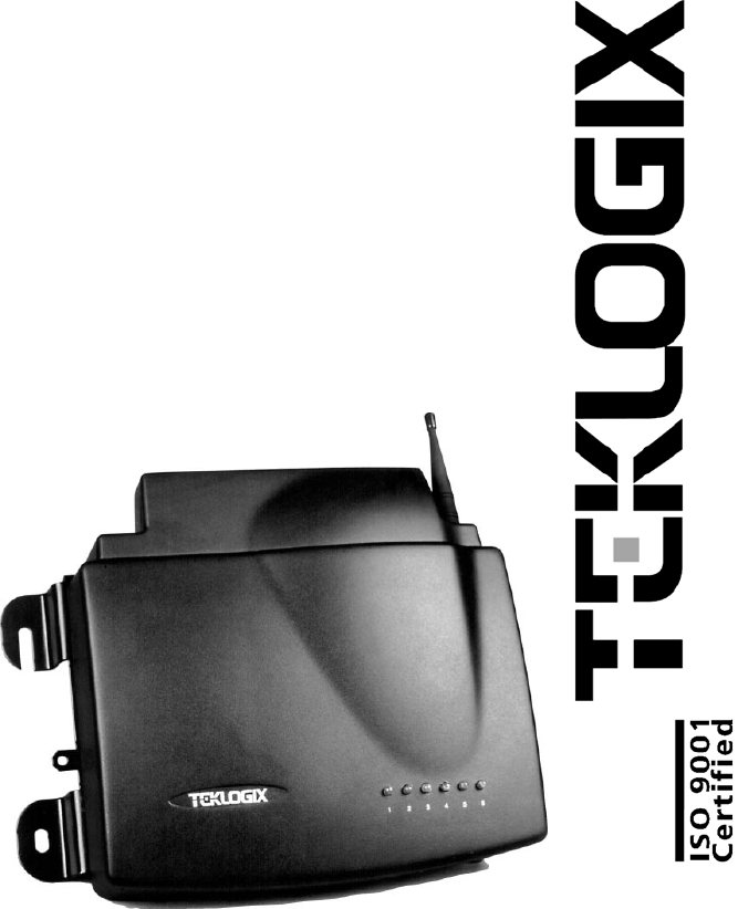
Figure 1.1 The 9150 Wireless Gateway - Front View
Figure 1.2 The 9150 Wireless Gateway - Bottom View

Chapter 1: Introduction
Base Station Functions
6Teklogix 9150 Wireless Gateway User Manual
1.3.1 Base Station Functions
As a base station, the 9150 provides a link between the local area network and the
wireless network consisting of Teklogix mobile terminals, and base stations such as
the 9140 Wireless Gateway. The 9150 and 9400/9300 Network Controller (or host
using a Teklogix Software Development Kit) communicate using the 9010 propri-
etary protocol with TCP/IP over Ethernet, Token Ring or serial connectivity. Wlan
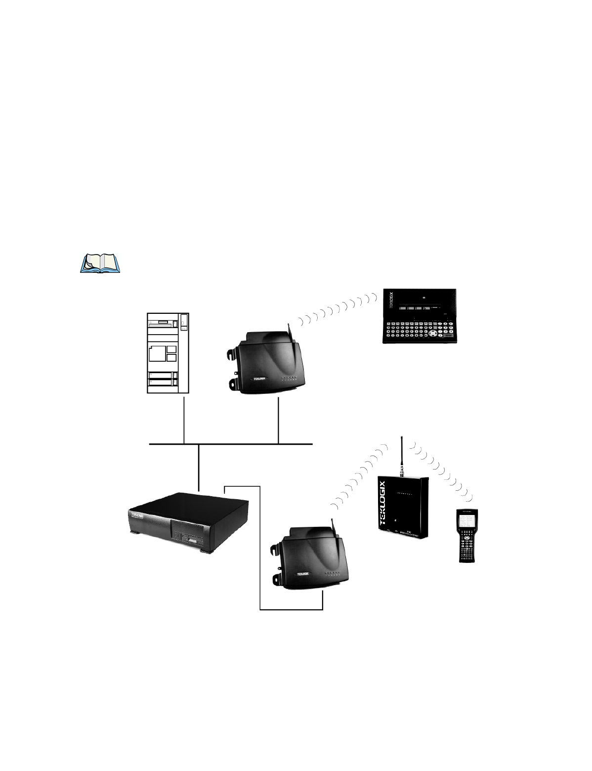
protocol enables the 9150 to communicate with 9140s without cable attachments
(see Figure 4.1 on page 47).
For information on configuring the 9150 as a base station, see Chapter 4: “Base
Station Configuration”. For details on Wlan, see “Wlan Protocol” on page 8.
1.3.2 Mini-Controller Functions
The 9150 is equipped with some emulation capabilities, allowing it to act as a mini-
controller. When a 9150 is configured as a mini-controller, Teklogix terminals can
emulate an ANSI, 5250 or 3274 terminal via a 9150 rather than through a 9400/9300
Network Controller.
To configure the 9150 as a mini-controller, see Chapter 5: “Mini-Controller Config-
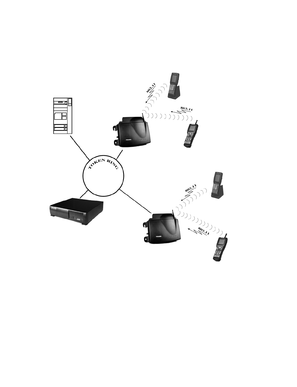
uration”. For a generalized system diagram, see Figure 5.1 on page 78.
1.3.3 Access Point Functions
As an access point, the 9150 Wireless Gateway forms a communication link
between Teklogix RF terminals or wireless access point clients and a Teklogix
Network Controller or a host computer. It communicates over an IEEE 802.11 RF
data link with terminals and over a cable with a network controller or a host com-
puter. The 9150 can be connected to the network through an Ethernet or Token Ring
connection. The diagram in Figure 6.1 on page 125 illustrates a 9150 access point
connection between a Teklogix 9400 Network Controller on Ethernet and IEEE
802.11 wireless devices. Figure 1.4 on page 12 shows a generalized Token
Ring configuration.
For information on the 9150 as an access point, see “IEEE 802.11 Protocol” on
page 10 and Chapter 6: “Access Point Configuration”.

Teklogix 9150 Wireless Gateway User Manual 7
Chapter 1: Introduction
Radio Options
1.4 Radio Options
The 9150 supports Type II PCMCIA cards so that multiple radio interfaces are possible.
There is one internal and one external PC card slot available. The type of PCMCIA
radio card installed in the 9150 is dependent on your wireless network. Currently
supported radios are:
•TRX7370 Narrow Band DSP.
•TekLAN 902 MHz DS Spread Spectrum (TRX7410).
•TekLAN 2.4 GHz DS Spread Spectrum (TRX7425).
•Proxim RangeLAN802 IEEE 802.11 FHSS 2.4 GHz (TRX7440).
•Lucent WaveLAN IEEE 802.11 DSSS 2.4 GHz (TRX7430).
The 9150 has dual-radio functionality. It can support several combinations of radio
types to function as both a mini-controller and base station, access point and base sta-
tion, or access point and mini-controller. The 902 MHz, 2.4 GHz (802.11 and TekLAN)
and Narrow Band radios can be used in any combination, with the exception of dual
TekLAN or dual Narrow Band radios.
Important: The radio in the terminal must match the radio in the 9150 Wireless
Gateway. If changing radio types in the 9150, DO NOT “hot swap”
the PC cards: Turn the 9150 off before changing the radio.
1.5 Radio Protocols
RF protocols allow terminals to communicate with a base station by sharing the use
of a radio channel in an efficient way. Teklogix systems use one of three types of RF
protocols: the Teklogix Adaptive Polling/Contention protocol, the Teklogix
Wireless LAN (Wlan) protocol, or the non-proprietary IEEE 802.11 protocol.
When used as a base station, the 9150 uses either the Adaptive Polling/Contention
protocol or the Wlan protocol. These two protocol types cannot be mixed on a
single system. When used as an access point device, the 9150 employs the
IEEE 802.11 protocol. These protocols are described in the following sections.

Chapter 1: Introduction
Adaptive Polling/Contention Protocol
8Teklogix 9150 Wireless Gateway User Manual
1.5.1 Adaptive Polling/Contention Protocol
The Adaptive Polling/Contention protocol is always used on Narrow Band radio
systems with baud rates of up to 19.2 kbps, and may also be used on Spread Spec-
trum systems at higher rates.
Terminals operating with this protocol do not transmit unless they receive polls from
the 9150. Terminals are generally polled en masse. Following each poll, groups of
terminals are assigned response windows in which they may respond to the poll.
If a “collision” occurs – more than one terminal attempts to respond in a particular
window – the 9150 that is polling divides and reassigns that group until the
colliding terminals can respond without a collision.
Adaptive features of this protocol allow the response windows to be adjusted to
accommodate high or low RF traffic conditions, and to prevent data from being
queued too long when a particular terminal has a burst of data to send or receive.
Systems using adaptive polling/contention can use the cellular option so that
terminal operators can roam the site, maintaining uninterrupted communication as
they pass between coverage areas.
If cellular base is not enabled, a “RESET: Press Enter” message appears on the
terminal screen each time an operator moves from one base station coverage area to
another. (Pressing <ENTER> restores communication, but some data may be lost.)
1.5.2 Wlan Protocol
The Wlan (Wireless LAN) protocol is used only on Spread Spectrum radio systems
at baud rates of 122 kbps and higher. The Wlan protocol allows base stations to be
added to a system without cable connections. A Wlan system consists of a minimum
of one wired base station and zero or more wireless base stations. It can operate on
either one channel – usually the case – or on multiple channels.
When a Wlan system is operating, base stations do not send out polls. Instead, both
wired and wireless base stations regularly broadcast routing information, indicating
the available routes back to the controller. Both terminals and wireless base stations
receive these broadcasts, determine the best communication route, and send their
messages. If a better route becomes available, the terminal or wireless base will
change communication paths.

Teklogix 9150 Wireless Gateway User Manual 9
Chapter 1: Introduction
Wlan Protocol
Only one base station or terminal may transmit at one time. When the channel
is clear, a combination of preset priorities and random choices determines who
“goes next”. Even if two transmitters attempt to send at the same time, message
acknowledgements and retransmissions prevent any data from being lost.
Terminals moving through the Wlan communicate with the base stations that
provide the best communication path to a wired base station. If multiple channels
are used, the terminal looks for a better channel only if it cannot find an acceptable
path back on its current channel.
Note: For detailed information on configuring the 9150 as a base station, please
see Chapter 4: “Base Station Configuration”. For a generalized system
diagram, see Figure 1.3, below.
Figure 1.3 9150 LAN And Serial Configuration
9150
ETHERNET
TCP/IP
9150
9140
8055 Vehicle-Mount
9400
7030 Hand-Held
SERIAL
Wireless Gateway
Network Controller
Wireless Gateway
RF Terminal
RF Terminal
Wireless Gateway
HOST

Chapter 1: Introduction
IEEE 802.11 Protocol
10 Teklogix 9150 Wireless Gateway User Manual
1.5.3 IEEE 802.11 Protocol
The IEEE 802.11 protocol is an OSI standard for Wireless Local Area Networks
(WLANs). With this standard, any IEEE 802.11 radio can communicate with any
other similarly-equipped device. However, IEEE 802.11 does not provide a standard
for a total WLAN system. IEEE 802.11 solely standardizes two communications
layers: Physical (PHY) and Medium Access Control (MAC). Three different PHY
layer media are covered: 2.4 GHz Direct Sequence Spread Spectrum radio,
2.4 GHz Frequency Hopping Spread Spectrum radio, and infrared. Each station
in a WLAN system has its own unique MAC address.
Important: Equipment using one physical medium (e.g. Frequency Hopping
versus Direct Sequence) will not interoperate with equipment using
a different physical medium.
IEEE 802.11 uses 2.4 GHz radios of relatively low power. The range is limited
to no more than a hundred feet or so, depending on the conditions, and is usually
restricted to “line of sight” operation. Therefore, most wireless networks need more
than one coverage area, with terminals moving between the areas. To integrate
those areas, systems using IEEE 802.11 protocol for their wireless networks
require an IEEE 802.11-equipped bridge device (or access point), such as the
9150 Wireless Gateway.
Using bridging software, the 9150 Wireless Gateway enables communication
between any wireless IEEE 802.11-equipped stations and LAN stations operating
on Ethernet or Token Ring. The 9150 itself is resident on the LAN and functions as
a MAC bridge, providing transparent integration between the stations on the wire-
less and wired networks.
Each terminal is associated with one 9150. A frame from an RF terminal is sent to
the 9150 that the terminal is associated with. The terminal puts a destination MAC
address in the frame, which specifies a hardware address on the wired LAN side.
Because the receiving 9150 is connected to an Ethernet or Token Ring network, it
encapsulates the data in an Ethernet or Token Ring frame, respectively, including the
destination MAC address specified by the terminal. The 9150 then sends the frame
onto the physical network; the frame is picked up by whichever device is at the des-
tination hardware address.

Teklogix 9150 Wireless Gateway User Manual 11
Chapter 1: Introduction
IEEE 802.11 Protocol
When sending frames from the LAN side, the sending device puts the MAC address
of the terminal in the frame header. Whichever 9150 has that terminal associated
with it, takes the frame and passes it over the RF to the terminal. By passing frames
in this way, the 9150 is acting as a MAC bridge.
1.5.3.1 Inter-Access Point Protocol (IAPP)
The Inter-Access Point Protocol (IAPP) is an extension to the IEEE 802.11 protocol.
IAPP facilitates roaming of mobile stations across different Basic Service Sets
(groups of stations and their access points), and specifies how access points commu-
nicate with each other.
In a multiple-9150 system, IAPP informs the other 9150 Wireless Gateways when a
new 9150 becomes active, and enables the awareness of the 9150s of each other.
With IAPP, an IEEE 802.11 system can operate on one or more channels, with
terminals moving between the 9150s. Although each terminal is associated with one
9150, it can reassociate with another 9150 to maintain uninterrupted communica-
tions. The newly-associated 9150 will receive the terminal’s data frames and pass
them onto the LAN. Returning frames are no longer accepted by the original 9150,
which has disassociated from that terminal. The returning frames are now accepted
by the newly-associated 9150 and passed over the RF to the terminal.
Note: For detailed information on configuring the 9150 as an access point,
please see Chapter 6: “Access Point Configuration”. For a generalized
system diagram, see Figure 1.4 on page 12.
Chapter 1: Introduction
IEEE 802.11 Protocol
12 Teklogix 9150 Wireless Gateway User Manual
Figure 1.4 9150 Access Point Configuration
9150
9150
9400
7040 Hand-Held
Wireless Gateway
Network Controller
Wireless Gateway
RF Terminal
HOST 7035 Hand-Held
RF Terminal
7040 Hand-Held
RF Terminal
7035 Hand-Held
RF Terminal

Teklogix 9150 Wireless Gateway User Manual 13
INSTALLATION REQUIREMENTS 2
2.1 Choosing The Right Location..................15
2.1.1 Environment.....................15
2.1.2 Maintenance.....................16
2.1.3 Power And Antenna Cables . . . . . . . . . . . . . 16
2.2 Connecting To External Devices.................17
2.2.1 Ports.........................17
2.2.2 Status Indicators (LEDs). . . . . . . . . . . . . . . 18
2.2.3 Preparing For LAN Installation . . . . . . . . . . . 18
2.2.3.1 Ethernet....................19
2.2.3.2 Token Ring. . . . . . . . . . . . . . . . . . . 19
2.2.4 Preparing For Serial Installation . . . . . . . . . . . 20
2.2.5 Connecting A Video Display Terminal . . . . . . . 21
2.3 Changing The Configuration With A Web Browser.......21

Teklogix 9150 Wireless Gateway User Manual 15
Chapter 2: Installation Requirements
Choosing The Right Location
Warning: The 9150 must be installed by qualified Teklogix personnel.
2.1 Choosing The Right Location
Typically, Teklogix conducts a site survey in the plant and then recommends the
preferred locations for the 9150s. These locations provide good radio coverage,
minimize the distance to the host computer or network controller, and meet the
environmental requirements.
2.1.1 Environment
The 9150 should be located in a well-ventilated area and should be protected from
extreme temperature fluctuations (i.e. direct heater output, shipping doors or
direct sunlight). If a protective cover is required, it must have enough ventilation
to maintain the 9150’s surface at or near room temperature. The 9150 should be
situated away from the path of vehicles and free from water or dust spray.
The 9150 should only be mounted in the upright position, as shown in Figure 2.1,
below. This orientation minimizes the risk of water entering the 9150, should the
unit accidentally be sprayed. The 9150 is attached to a vertical surface using four
fasteners on the rear plate (type of fasteners are dependent on mounting surface).
The top two holes in the rear plate are slots, allowing the unit to be hung in position
before the remaining bolts are installed, thus easing installation. The bolts used for
installation are SAE 1/4-20.
Figure 2.1 9150 Installation Position
Mounting Slot
Cable Tie Mount
Mounting Hole

Chapter 2: Installation Requirements
Maintenance
16 Teklogix 9150 Wireless Gateway User Manual
Refer to Chapter 7: “Specifications” for a more detailed description of environmen-
tal requirements. Keep in mind that the long term stability of this equipment will
be enhanced if the environmental conditions are less severe than those listed in
this manual.
2.1.2 Maintenance
The 9150 has no internal option switches and does not require physical access;
all configuration settings are done remotely (see Chapter 3: “9150 Main Configura-
tion”). Environmental and radio communication considerations do, however,
still apply.
2.1.3 Power And Antenna Cables
To prevent accidental disconnection and stress on the 9150, antenna and power
cables should be secured within 30 cm of the unit. Secure the cables with ties to
the cable tie mounts on the 9150 (see Figure 2.1 on page 15). A single phase power
outlet (range 100 to 240 VAC rated 1.0A minimum) should be installed within one
metre (3.1 feet) of the 9150. The 9150 automatically adjusts to input within that
power range. The power cable is removable and is available in the power type spe-
cific to your location.
Warning: To avoid electric shock, the power cord protective grounding
conductor must always be connected to ground.
There are several omnidirectional antennas available from Teklogix. The type of
antenna required for each installation depends on the coverage requirements and
the frequencies used. Generally, a site survey determines the appropriate antenna.
Teklogix can also provide special, directional antennas. Consult Teklogix service
personnel for more information.
Warning: Never operate the 9150 without a suitable antenna or a
dummy load.
Connection to Outdoor Antenna: Outdoor antenna to be earthed in
accordance with International Standard EN 50083-1 (1993),
“Cabled Distribution Systems for Television and Sound Signals -
Safety Requirements”. The antenna must be installed by a
qualified service person and installed according to local electrical
installation codes.
Teklogix 9150 Wireless Gateway User Manual 17
Chapter 2: Installation Requirements
Connecting To External Devices
Teklogix supplies the coaxial cable required to connect the 9150 to the antenna.
When determining the location of the antenna, the coverage requirements of the
antenna are considered in conjunction with the environmental requirements
of the 9150.
The coaxial cable must be routed and secured using wire anchors and/or coaxial nail
clips. A few extra inches of cable are required near the antenna and the 9150 to
make disconnection easier.
2.2 Connecting To External Devices
This section contains general guidelines for connecting the 9150 to external
devices such as network controllers, base stations, host computers, PCs and video
display terminals.
2.2.1 Ports
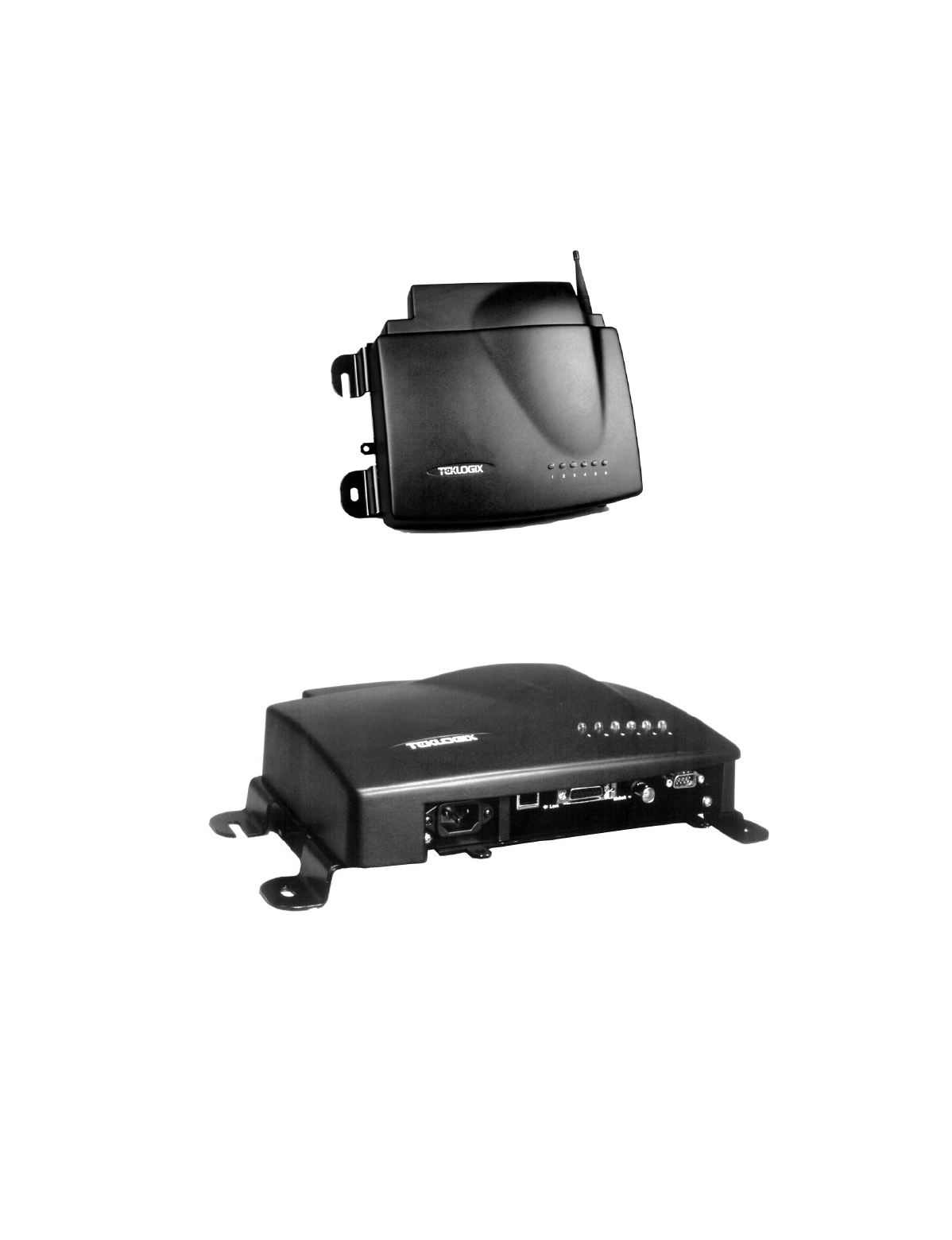
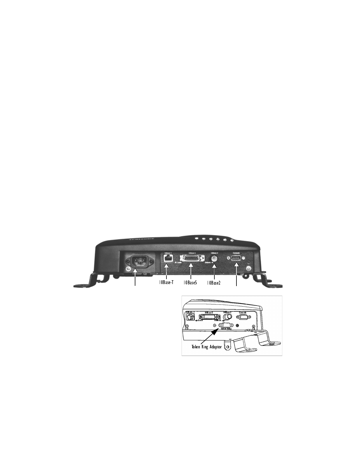
Figure 2.2 below shows the locations of the port and power connectors on the under-
side of the 9150. The port pinouts are described in Appendix A: “Port Pinouts And
Cable Diagrams”.
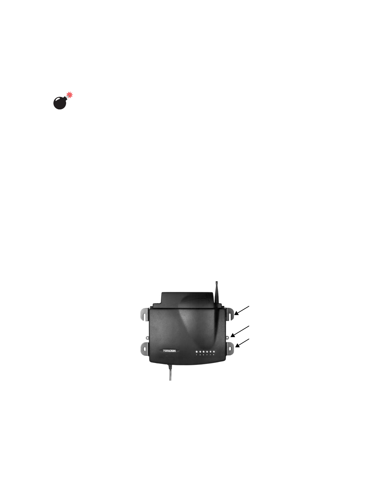
Figure 2.2 Base Of The 9150 (inset: optional Token Ring adaptor)
AC Power Socket Console Port
On-Board Ethernet Adaptors

Chapter 2: Installation Requirements
Status Indicators (LEDs)
18 Teklogix 9150 Wireless Gateway User Manual
2.2.2 Status Indicators (LEDs)
The 9150 has six status indicators on the front of the enclosure. These numbered and
coloured LEDs indicate the operating status for each port:
2.2.3 Preparing For LAN Installation
Because the 9150 provides Ethernet or Token Ring connectivity, it can be added to
an existing LAN. Generally, LAN installations are handled with the help of the
network administrators, as they are familiar with their network and its configuration.
Once the 9150 is installed, connected and powered on, the system administrator
can access the unit to check the configuration and to assign the 9150 its unique IP
address. This may be done through the Console port or through the network (see
“Connecting A Video Display Terminal” on page 21 and “Changing The Configura-
LED
Number Name Function Colour
1 Ethernet link1 Link indicator for 10base-T:
ON = good link; OFF = no link yellow
2 Ethernet activity Ethernet LAN activity (Rx/Tx) green
3PC Card A status
2PC Card A activity (Rx/Tx) yellow
4 PC Card B status2,3 PC Card B activity (Rx/Tx; Token Ring) green
5 SLIM SLIM card activity yellow
6Power
LED flashing = BIST4 running/error detected
LED On solid = BIST4 Passed
LED Off = no power to unit
green
1 For 10Base2 and 10Base5: LED 1 is always OFF when these connections are used.
2 When a TekLAN 902 MHz radio is installed, the PC Card status LEDs blink only when
data is received from or transmitted to a terminal. When a TRX7370 narrow band radio is
installed, these LEDs blink for all received and transmitted data traffic.
3 When a Token Ring PC card is installed, LED #4 shows Token Ring activity.
4 Built-in Self-Test.
Table 2.1 LED Functions

Teklogix 9150 Wireless Gateway User Manual 19
Chapter 2: Installation Requirements
Preparing For LAN Installation
tion With A Web Browser” on page 21). Subsequent changes in the network, such as
the addition of stations or users, would also require that the 9150 configuration
be changed.
Important: Once the 9150 is configured and rebooted the first time, the
“Employ bootp” parameter should be disabled (see page 38),
unless the 9150 obtains its IP address from a bootp server or the
system administrator intends to update the software through bootp.
2.2.3.1 Ethernet
The 9150 is equipped with three variations of Ethernet connection: 10Base-T
(RJ-45), 10Base2 (BNC coax), and 10Base5 (Dsub 15). See Figure 2.2 on page 17
for an illustration of the connector locations. Since these ports are auto-selecting,
jumper or configuration settings are not required. The maximum packet size sup-
ported over the network is 1500 bytes. This parameter is not set at the 9150, but
should be set at the host.
For a description of port pinouts, please refer to Appendix A: “Port Pinouts And
Cable Diagrams”.
Note: 10Base2 termination is not required if the port is not used.
2.2.3.2 Token Ring
To connect a 9150 to a Token Ring network, a Madge Token Ring Smart 16/4 Ring-
node Adapter Type II PC card, 4 or 16 Mbps, is pre-installed in the internal PC card
slot. The connector plate shown in the inset in Figure 2.2 on page 17 is fixed to the
base of the 9150 to accommodate the Token Ring Dsub9 cable. This connection
supports Shielded Twisted Pair (IBM STP) cables Type 1 or 6. The maximum
packet size supported over the network is 1500 bytes. This parameter is not set at
the 9150, but should be set at the host.
For a description of port pinouts, please refer to Appendix A: “Port Pinouts And
Cable Diagrams”.

Chapter 2: Installation Requirements
Preparing For Serial Installation
20 Teklogix 9150 Wireless Gateway User Manual
2.2.4 Preparing For Serial Installation
The 9150 offers serial connection as an option when a local area network is not
used. Data cables are generally prepared after the site survey report is available and
should be in place before the equipment arrives so that Teklogix can install them.
The type of data cable used depends on the type of port required at the site. The type
of port depends on the location of the 9150 and whether it is to be connected to a
host computer or a network controller. Modems can be used to better accommodate
long distances between the 9150 and the host computer or network controller.
Port options include RS-232 Plus and Current Loop. Connector pinouts are listed in
Appendix A: “Port Pinouts And Cable Diagrams”. The baud rate and the
maximum length of the cable for each type of port is tabulated in Table 2.2, below.
The cable lengths are based on a quality, 2-pair shielded cable (Belden #8723). The
default baud rate for the 9150 serial connection is 19.2k.
Each method of connection has different advantages and capabilities:
•RS-232/Current Loop – This is a standard RS-232 asynchronous port with
extra lines for synchronous communication. Cable length is limited by the
RS-232 specification of 2500pF on the capacitance of the receiving stations.
An optional current loop is available to extend the limits of this connection.
•Optically isolated RS-232-Plus – This is a standard RS-232 asynchronous
port with an RS-423 driver. Cables connected to this port can span longer
distances at higher baud rates than the RS-232/Current Loop option.
Table 2.2 Maximum Cable Lengths For RS-232 Plus And Current Loop
Port Options Cable Part No. Baud Rate Max. Length
RS-232 Plus
(asynchronous
communications only)
16590, 16598,
19387
up to 19.2k 2250 ft.
38.4k 2000 ft.
Current Loop
20 mA
(asynchronous
communications only)
16599
2400 6250 ft.
9600 3250 ft.
19.2k 1500 ft.
38.4k 1000 ft.

Teklogix 9150 Wireless Gateway User Manual 21
Chapter 2: Installation Requirements
Connecting A Video Display Terminal
Warning: Installation using an outdoor data cable between two buildings
requires that transient protection (a lightning arrestor) be added
to the data cable. The RS-232 Plus port is recommended in this
situation because it provides optical isolation between the cable
and the controller.
To avoid ground problems (on the data cables), the 9150 should be connected to the
same transformer/voltage distribution system as the network controller. If this is not
possible, use Current Loop ports or a pair of modems.
2.2.5 Connecting A Video Display Terminal
An ANSI compatible video display terminal (e.g., DEC VT220 or higher), or a PC
running terminal emulation, is used for diagnostic purposes and to configure the IP
address for the first time before the 9150 can be accessed using a Web Browser (see
“Configuring The IP Address” on page 25).
The terminal is connected to the port labelled “Console” on the 9150 (see Figure 2.2
on page 17). This port is normally set to operate at 19,200 baud, 8 bits, 1 stop bit, no
parity. To comply with Part 15 of the FCC rules for a Class B computing device,
only the cable supplied (Part no. 19387) should be used.
2.3 Changing The Configuration With A Web Browser
The 9150 Flash memory can be reconfigured remotely via the network using a stan-
dard HTML Web Browser such as Netscape Navigator (version 4.05 or later) or MS
Internet Explorer (version 4.0 or later). See Chapter 3: “9150 Main Configuration”
for instructions on changing the parameters.
When setting up the 9150 as an access point device, refer to Chapter 6: “Access
Point Configuration” for additional information.
When setting up the 9150 as a base station, please refer to Chapter 4: “Base Station
Configuration” for additional information.
When setting up the 9150 as a mini-controller, please refer to Chapter 5: “Mini-
Controller Configuration” for additional information.


Teklogix 9150 Wireless Gateway User Manual 23
9150 MAIN CONFIGURATION 3
3.1 Configuration Main Menu....................25
3.2 Configuring The IP Address...................25
3.3 Accessing The Menus ......................27
3.4 General Configuration Options.................29
3.4.1 Interfaces.......................30
3.4.1.1 Onboard Ethernet . . . . . . . . . . . . . . . 30
3.4.1.2 Slot n: Token-Ring. . . . . . . . . . . . . . . 32
3.4.1.3 Slot n: PC Card Radio . . . . . . . . . . . . . 34
3.4.2 Users.........................34
3.4.3 SNMP........................35
3.4.3.1 System Parameters. . . . . . . . . . . . . . . 36
3.4.3.2 SNMP Communities..............36
3.4.3.3 Trap Receivers.................36
3.4.4 TCP/IP Parameters..................36
3.4.4.1 Host Table...................37
3.4.4.2 Bootp .....................38
3.4.4.3 DNS......................39
3.4.5 Serial Ports Parameters................40
3.4.5.1 Console Port . . . . . . . . . . . . . . . . . . 40
3.4.5.2 Serial Port...................40
3.5 Access Point/Base Station Configurations. ...........41
3.6 Miscellaneous Commands . . ..................42
3.6.1 System Info .....................42
3.6.2 Reboot Unit . . . . . . . . . . . . . . . . . . . . . 43


Teklogix 9150 Wireless Gateway User Manual 25
Chapter 3: 9150 Main Configuration
Configuration Main Menu
3.1 Configuration Main Menu
The 9150 Flash memory can be reconfigured remotely via the network using a
standard HTML Web Browser such as Netscape Navigator (version 4.05 or later) or
MS Internet Explorer (version 4.0 or later). The 9150 Configuration program allows
various configuration parameter settings to be changed, added or deleted.
Important: The 9150 must be warm rebooted after parameter changes are made ,
including configuring the IP address (see below), in order for the
changes to take effect. For details, see “Reboot Unit” on page 43.
3.2 Configuring The IP Address
Before the configuration menus can be accessed using your Web Browser, the 9150
must be assigned an IP address using a PC console connection. Virtually any PC
can be connected to the console port of the 9150, provided that the PC has a
terminal communication program such as the Windows “HyperTerminal” utility or
“Procomm Plus” for Windows. These programs emulate an ANSI terminal such as
VT220 or higher. Cable no. 19387 should be used to connect the PC to the 9150.
Make sure the communications settings on your PC are set to 8 bits, 1 stop, no
parity, and that the baud rate of the serial port matches that of the 9150 console port
(19,200 baud).
After the PC is attached and turned on, press the <RETURN> key several times until
the “>” prompt appears. The commands used to configure IP addresses are
described here.
If your system uses a bootp server to assign IP addresses, make sure that “bootp” is
enabled. Once enabled, and the 9150 is rebooted, you will be able to access the
9150 configuration menus through the Web Browser, using the IP address identified
in the server's bootp table. If you do not use a bootp server, make sure that “bootp”
is disabled and continue with the configuration commands to manually assign an
IP address.
Important: When your configuration is completed, the changes should be
saved to flash by entering the following command (commands are
case-sensitive):
>cfg commitCache

Chapter 3: 9150 Main Configuration
Configuring The IP Address
26 Teklogix 9150 Wireless Gateway User Manual
To display the bootp setting:
>cfg get system.dobootp
To enable bootp:
>cfg put system.dobootp 1
To disable bootp:
>cfg put system.dobootp 0
To display the default IP address (xxx.xxx.xxx.xxx represents the IP address):
>cfg get interface.1.defaultipaddress
To configure the default IP address
>cfg put interface.1.defaultipaddress xxx.xxx.xxx.xxx
To display the default gateway:
>cfg get system.defaultgateway
To configure the default gateway:
>cfg put system.defaultgateway xxx.xxx.xxx.xxx
To display the default subnetmask:
>cfg get interface.1.defaultsubnetmask
To configure the default subnetmask:
>cfg put interface.1.defaultsubnetmask xxx.xxx.xxx.xxx

Teklogix 9150 Wireless Gateway User Manual 27
Chapter 3: 9150 Main Configuration
Accessing The Menus
3.3 Accessing The Menus
When the Web Browser is pointed to the 9150’s IP address, a name and password
dialog box appears. The password is comprised of alphanumeric characters and is
case-sensitive. If you change the password (see “Users” on page 34), set all 9150s to
the same password, and write it down in a secure place.
A default user name “user” and the password “123456” are created on 9150 system
startup if no users are already configured. You can use the default to enter the
Configuration Main Menu for the first time. For security, change this default name
and password immediately after entering the configuration menus. Should you acci-
dentally delete your user names, re-booting the 9150 will re-create the default name
and password so that you can get back in to the unit.
After the password is accepted, the Configuration Main Menu appears. The 9150
software automatically detects the system information of the unit, and most of the
parameters have already been properly configured for each site.
Warning: Parameters should not be altered without a clear understanding of
how they operate. Parameters that are incorrectly set can increase
response time or cause communication difficulties.
•To highlight and move through the different options, use the <TAB> key
or mouse pointer.
•To view and select the items in the listboxes, either press the <UP> or
<DOWN> arrow keys or click on the arrow at the side of the menu and
highlight the item.
•To enter the related configuration sub-menu dialog box, highlight
“Configure” and either press <ENTER> or click on the “Configure” button.
•Where string entry parameters are given in the menus, changes are keyed in.
Numerical parameters can be entered as hexadecimal values. Precede hexa-
decimal values with “0x”.
•To leave a menu page, select either the <OK> or <Cancel> button at
the bottom of the page. Selecting <OK> will save your changes and
exit the page, while selecting <Cancel> will exit the page without saving
the changes.
Important: Do not use the Web Browser’s <Back> button to leave a page.
Chapter 3: 9150 Main Configuration
Accessing The Menus
28 Teklogix 9150 Wireless Gateway User Manual
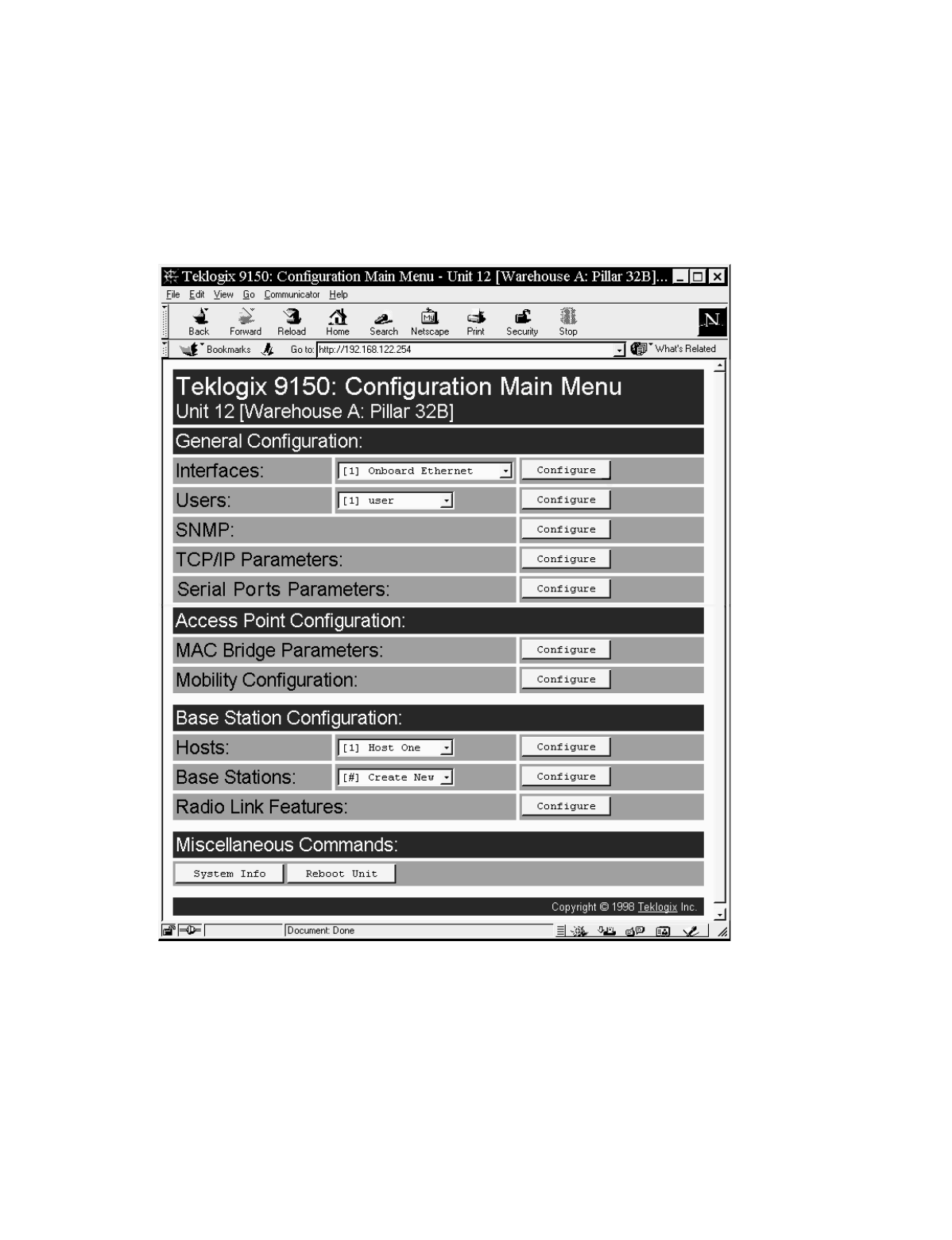
Figure 3.1 9150 Configuration Main Menu: View From Browser
Teklogix 9150 Wireless Gateway User Manual 29
Chapter 3: 9150 Main Configuration
General Configuration Options
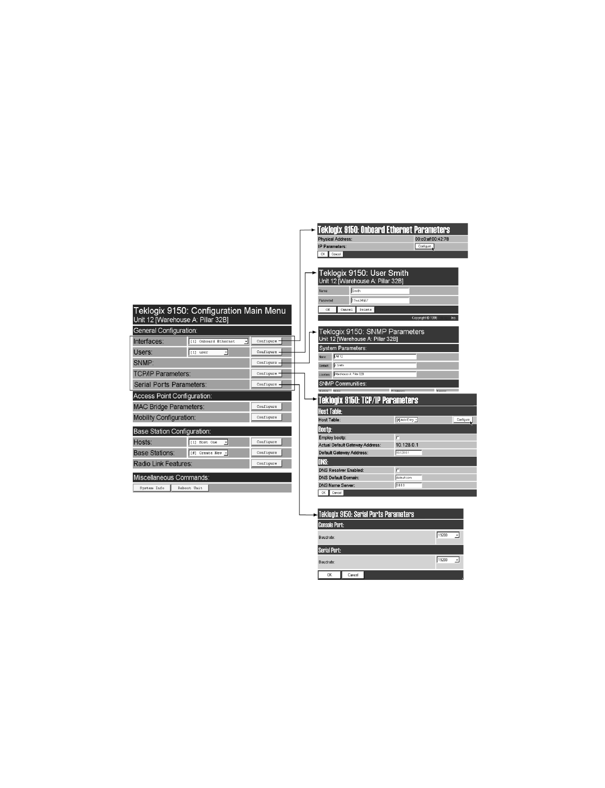
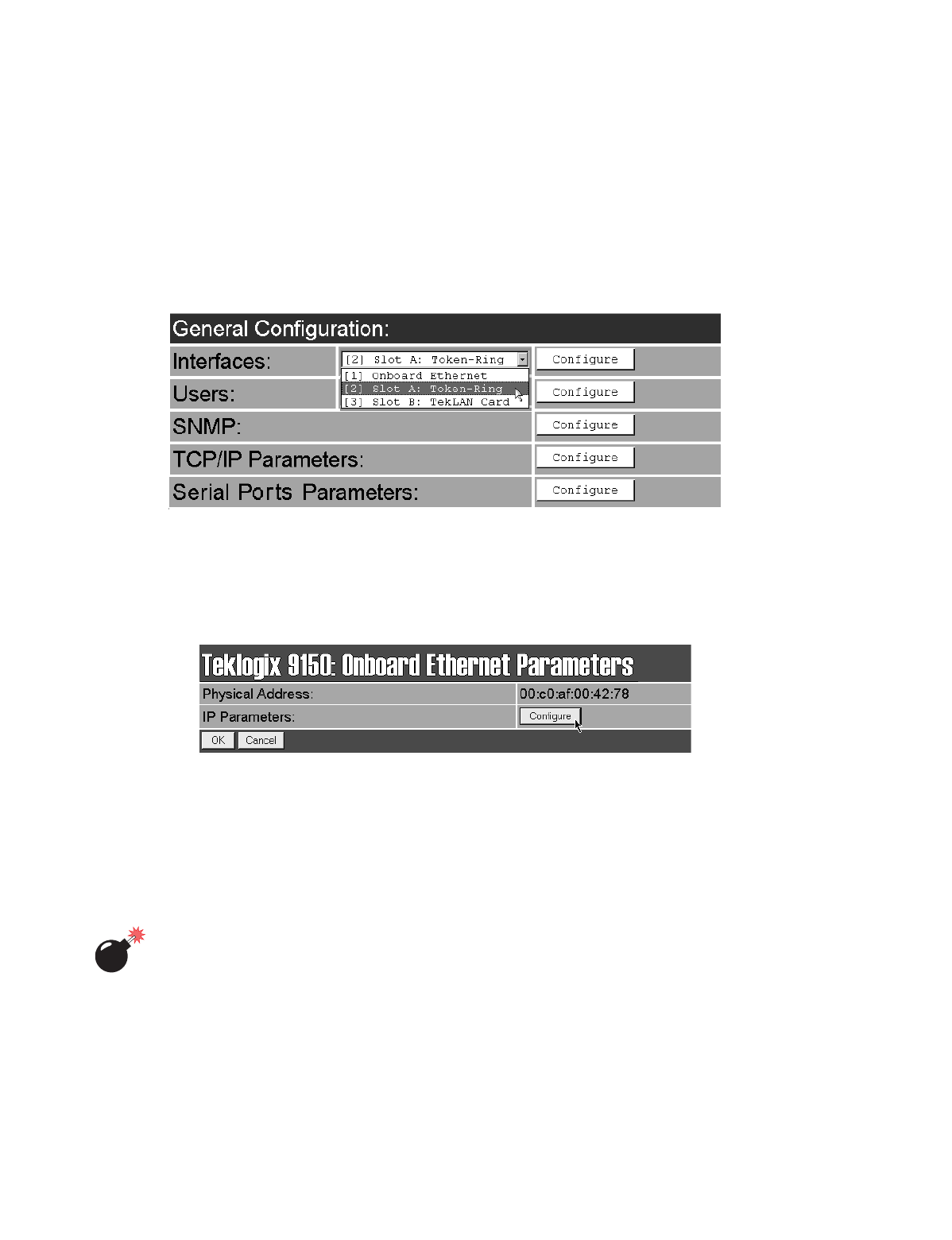
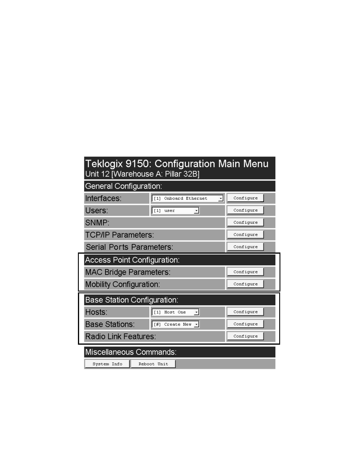
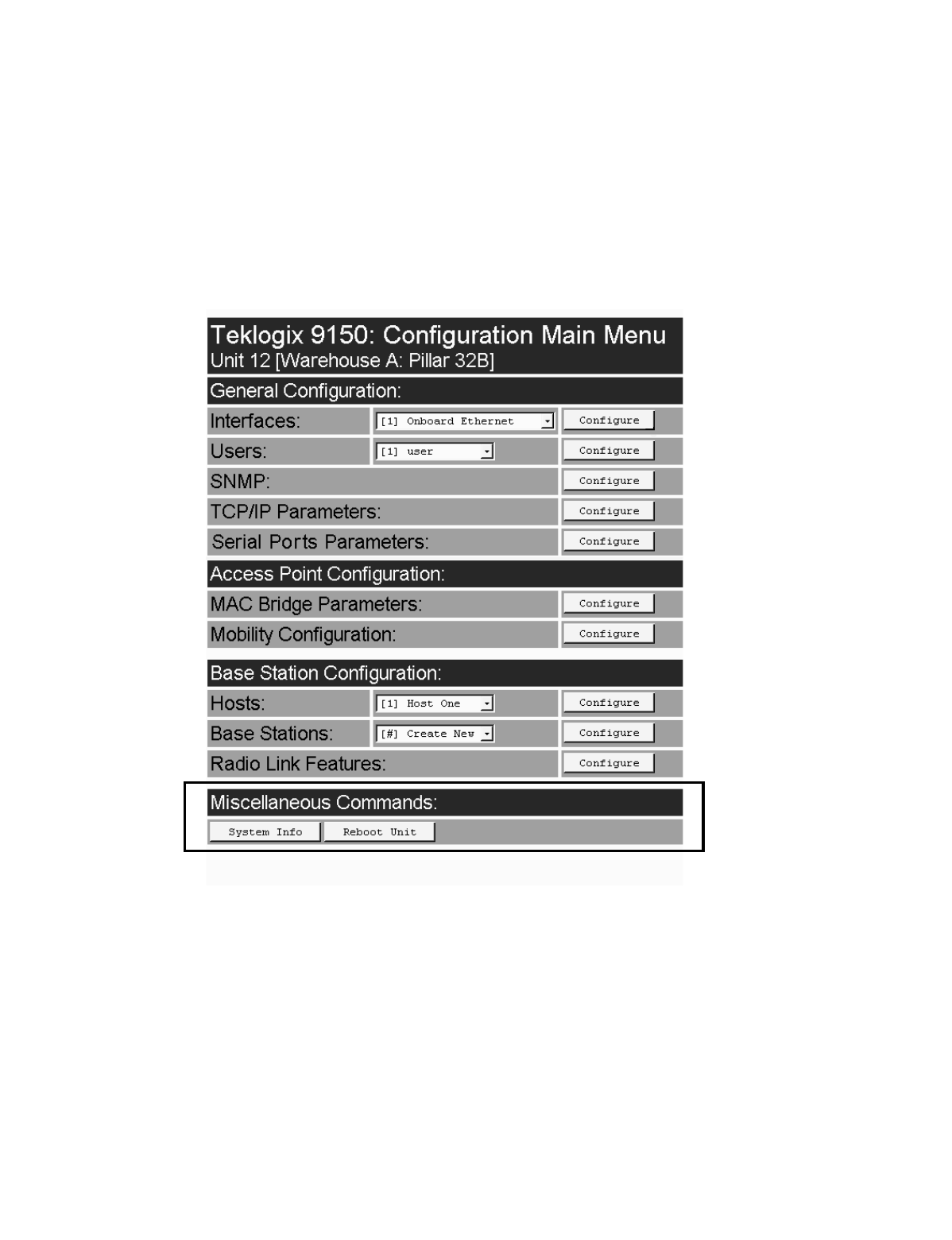
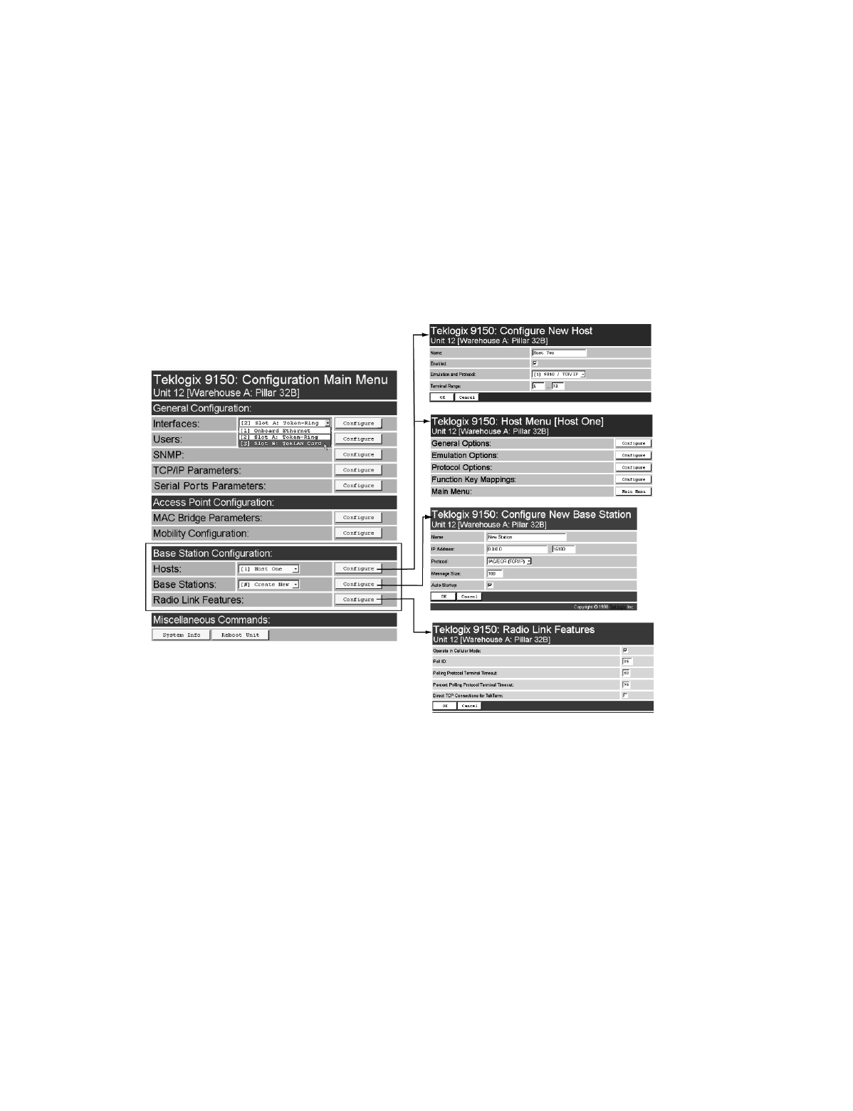
3.4 General Configuration Options
The General Configuration menu on the Configuration Main Menu page presents
five options of sub-menus: Interfaces , Users, SNMP, TCP/IP Parameters, and
Serial Ports Parameters.
Figure 3.2 Overview Of General Configuration Menus
Chapter 3: 9150 Main Configuration
Interfaces
30 Teklogix 9150 Wireless Gateway User Manual
3.4.1 Interfaces
The pull-down menu shown for the Interfaces option indicates which interfaces have
been detected in use by the 9150.
3.4.1.1 Onboard Ethernet
For the selection Onboard Ethernet, entering the “Configure” dialog box will open
the parameters page for the Ethernet connection, which shows the 9150’s physical
(hardware) address and IP address parameters.
Physical Address
A unique Physical Address is assigned by Teklogix personnel for each 9150. The
values entered for this parameter are presented in hexadecimal in descending order
beginning with the MSB (Most Significant Byte), the highest value, and ending with
the LSB (Least Significant Byte), the lowest value. The allowable value for each
field ranges from 00 to FF.
Warning: It is not advisable to modify the Physical Address. However, if these
values are changed, the Network Administrator must assign a
unique address to each Ethernet station on the network, including
all 9150s.
Teklogix 9150 Wireless Gateway User Manual 31
Chapter 3: 9150 Main Configuration
Interfaces
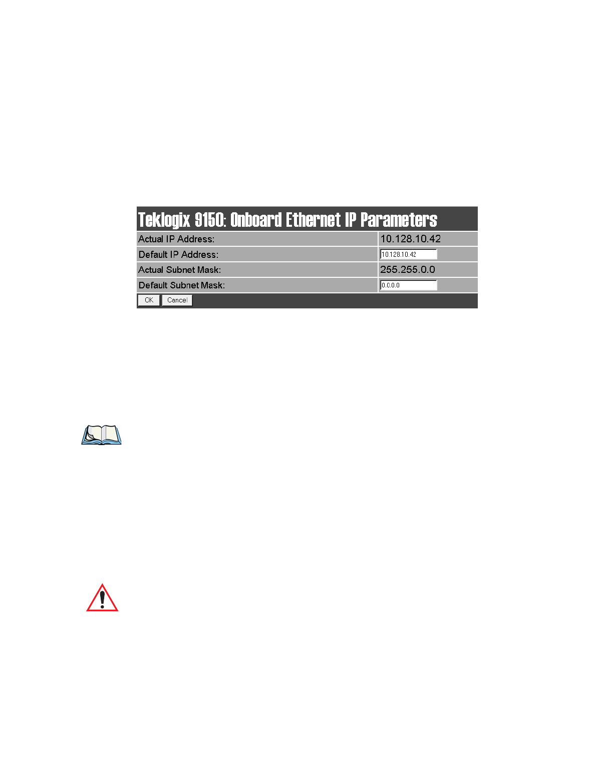
IP Parameters
Each 9150 that is connected to a local network has a unique IP address designated
for it. The IP Parameters used to assign the IP address are accessed by entering the
“Configure” dialog box.
Actual IP Address
The Actual IP Address is the IP address currently set on the 9150.
Default IP Address
This parameter allows you to change the value of the IP address. The IP
address must be a unique value on the network, including any Token Ring
IP addresses being used, so that each 9150 in your system can be identified.
The acceptable value ranges from 0.0.0.0 to 239.255.255.255.
Note: The value 255.255.255.255 is reserved for the broadcast address.
Actual Subnet Mask
The Actual Subnet Mask is the subnet mask currently set on the 9150.
Default Subnet Mask
This parameter allows you to change the value of the subnet mask. The 9150 uses
the Default Subnet Mask, its own IP address, and the destination IP address to deter-
mine if a packet should be sent on the local network or to a remote segment. If the
destination is found on the local network, the packet is sent directly to its destina-
tion. If the destination resides on a remote network, the packet is routed to the gate-
way. Enter your subnet mask in “xxx.xxx.xxx.xxx” notation.
Important: The maximum packet size supported is 1500 bytes. This parameter
is not set at the 9150, but should be set at the host.
Chapter 3: 9150 Main Configuration
Interfaces
32 Teklogix 9150 Wireless Gateway User Manual
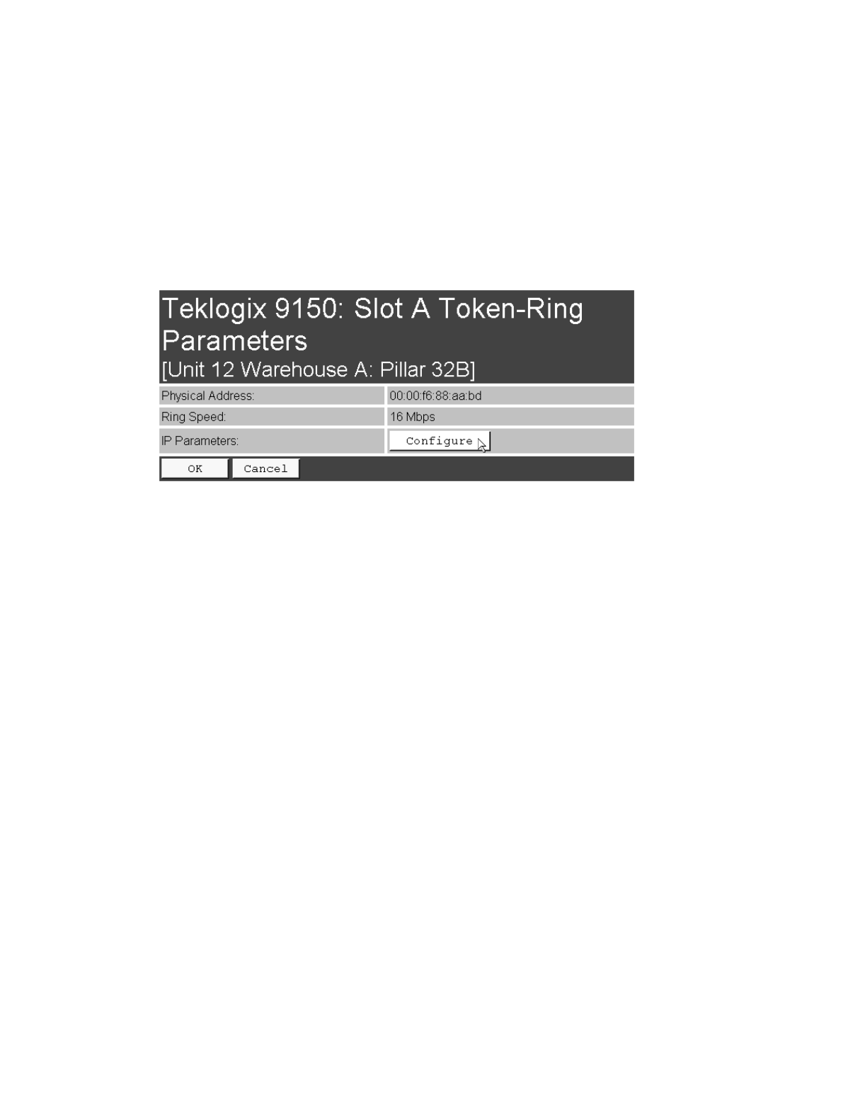
3.4.1.2 Slot n: Token-Ring
For the selection Slot n: Token-Ring, entering the “Configure” dialog box will open
the parameters page for the Token Ring connection, which shows the 9150’s physi-
cal (hardware) address, ring speed, and IP address parameters.
Physical Address
Each Madge Token Ring PC card has a unique MAC address (Physical Address),
which is displayed here in the 9150 parameters. The MAC address is presented in
standard hexadecimal format.
Ring Speed
This parameter indicates the Token Ring network speed. The ring speed must be set
through the console, prior to installation, using the configuration command line:
>cfg put interface.#.tokenring.datarate 16
(or 4 if the network is running at 4 Mbps)
The ‘#’ depends on which slot the PC card occupies. Usually this is slot B, inside the
9150, so the # would be 3. The default ring speed is 16 Mbps.
Teklogix 9150 Wireless Gateway User Manual 33
Chapter 3: 9150 Main Configuration
Interfaces
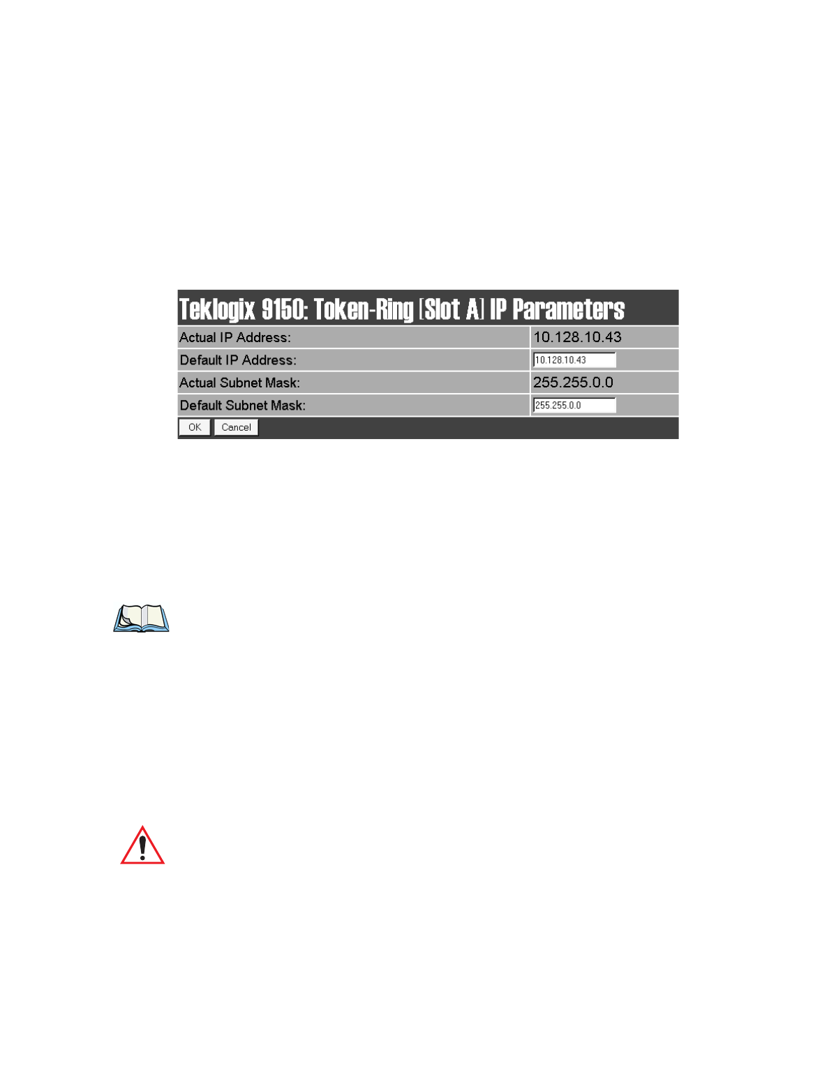
IP Parameters
Each 9150 that is connected to a local network has a unique IP address designated
for it. The IP Parameters used to assign the IP address are accessed by entering the
“Configure” dialog box.
Actual IP Address
The Actual IP Address is the IP address currently set on the 9150.
Default IP Address
This parameter allows you to change the value of the IP address. The IP address
must be a unique value on the network, including any Ethernet IP addresses being
used, so that each 9150 in your system can be identified. The acceptable value
ranges from 0.0.0.0 to 239.255.255.255.
Note: The value 255.255.255.255 is reserved for the broadcast address.
Actual Subnet Mask
The Actual Subnet Mask is the subnet mask currently set on the 9150.
Default Subnet Mask
This parameter allows you to change the value of the subnet mask. The 9150 uses
the Default Subnet Mask, its own IP address, and the destination IP address to deter-
mine if a packet should be sent on the local network or to a remote segment. If the
destination is found on the local network, the packet is sent directly to its destina-
tion. If the destination resides on a remote network, the packet is routed to the gate-
way. Enter your subnet mask in “xxx.xxx.xxx.xxx” notation.
Important: The maximum packet size supported is 1500 bytes. This parameter
is not set at the 9150, but should be set at the host.
Chapter 3: 9150 Main Configuration
Users
34 Teklogix 9150 Wireless Gateway User Manual
3.4.1.3 Slot n: PC Card Radio
Each PC (PCMCIA) card radio resident in the 9150 will be located in one of two
Slots: A or B. Selecting a PC card will open the sub-menu for that radio.
IEEE 802.11 FH or DS: See “IEEE 802.11 (Frequency Hopping Radio Parame-
ters)” on page 126, or “IEEE 802.11 (Direct Sequence Radio Parameters)” on page
128 for details on setting the radio parameters for the PC card.
TekLAN Card: See “TekLAN Parameters” on page 49 for details on setting the radio
and Wlan parameters.
Teklogix Narrowband: See “Narrow Band Radio Parameters” on page 53 for details
on setting the radio and polling parameters.
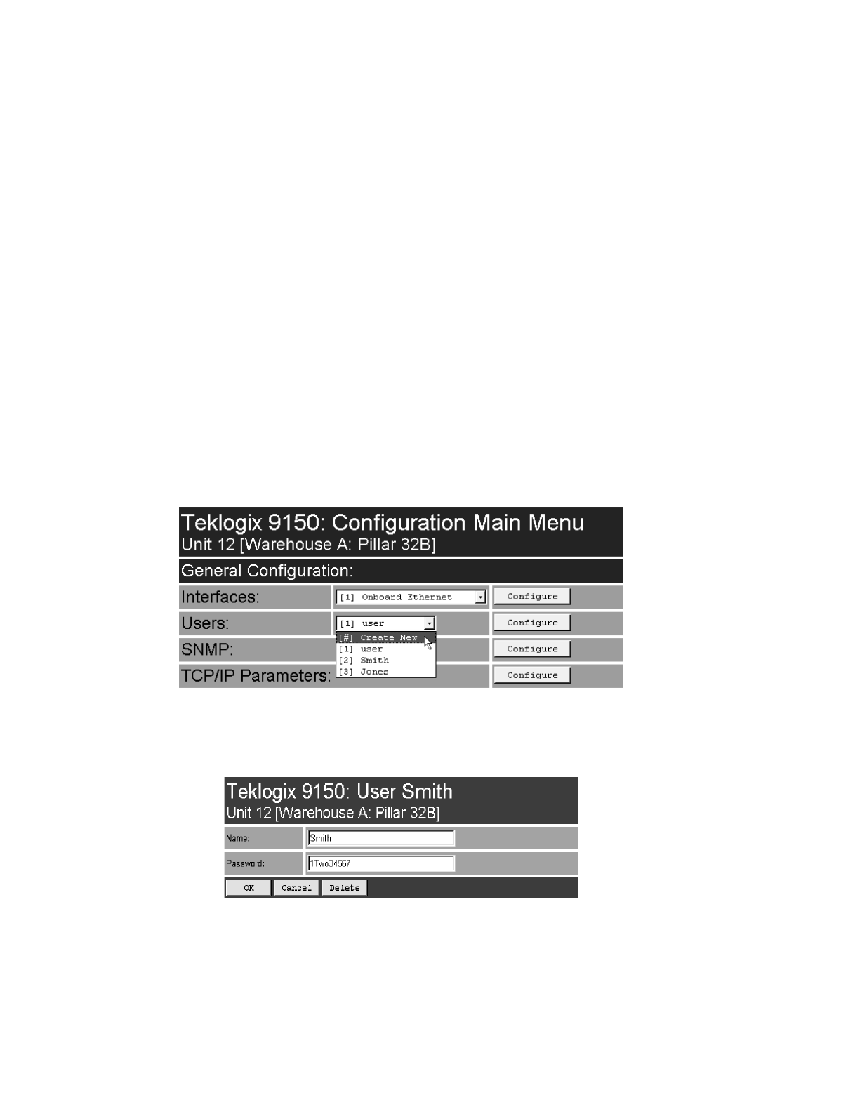
3.4.2 Users
The Users option provides security for access to the 9150 Configuration menus.
New individuals can be added by selecting “[#] Create New” in the listbox before
entering the “Configure” dialog box.
Individual names and their assigned passwords may be changed or deleted in the
“Configure” dialog box for this option by selecting the name in the listbox
and then opening the “Configure” dialog box. The password can be comprised of
alphanumeric characters and is case-sensitive.
Teklogix 9150 Wireless Gateway User Manual 35
Chapter 3: 9150 Main Configuration
SNMP
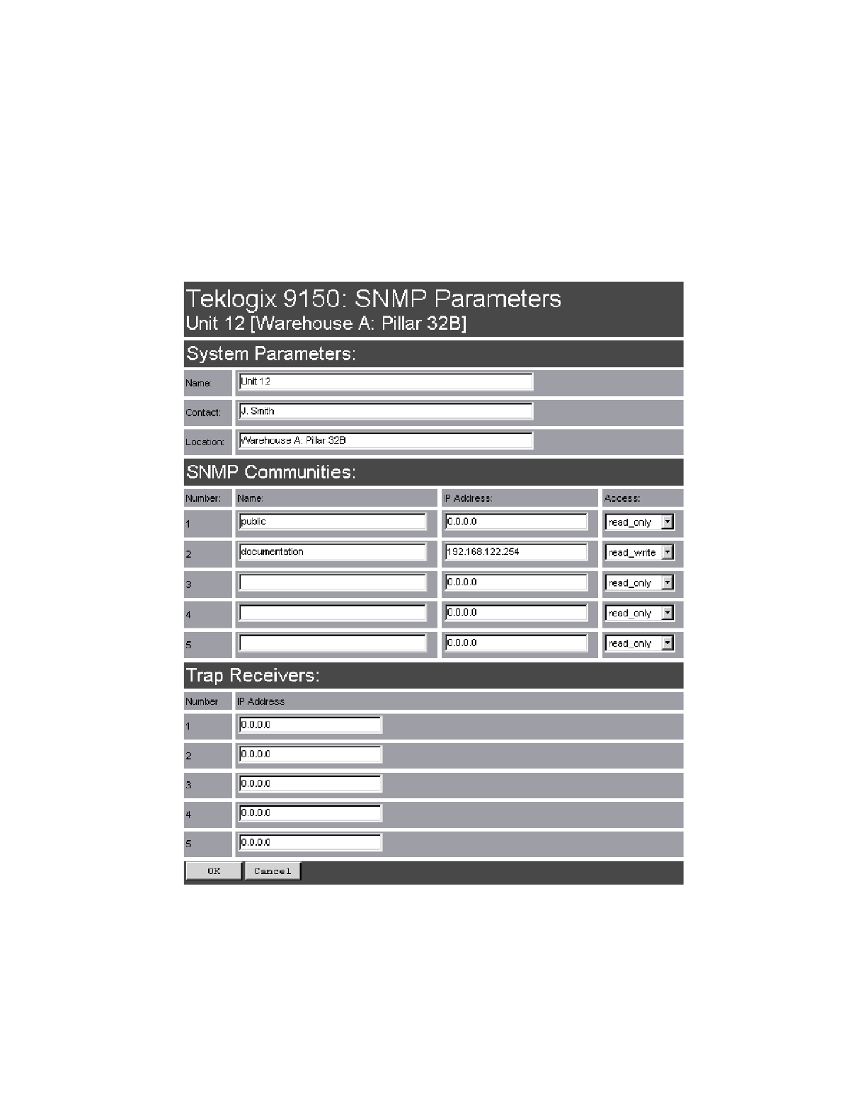
3.4.3 SNMP
The SNMP (Simple Network Management Protocol) “Configure” page allows
various network management parameters to be set or changed.
Chapter 3: 9150 Main Configuration
TCP/IP Parameters
36 Teklogix 9150 Wireless Gateway User Manual
3.4.3.1 System Parameters
The entries in these parameters set the name, contact and location identifiers for
this specific 9150 Wireless Gateway. The name and location are then shown as the
sub-heading of each Configuration page. In this example the identifier appears as
“Unit 12 [Warehouse A: Pillar 32B]”.
3.4.3.2 SNMP Communities
These parameter settings allow the network administrator to define the network
environment and determine the type of access allowed (read-only, or read-write) for
each area name and IP address.
3.4.3.3 Trap Receivers
These IP addresses determine which SNMP manager’s stations will receive SNMP
Traps from the 9150. The 9150 sends the “Cold Start” Trap on reboot or power up.
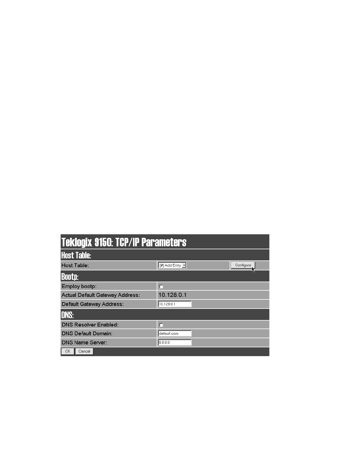
3.4.4 TCP/IP Parameters
The 9150 is situated on a wired network which uses TCP/IP. Both Bootp and DNS
options are available to resolve IP addressing issues.
Teklogix 9150 Wireless Gateway User Manual 37
Chapter 3: 9150 Main Configuration
TCP/IP Parameters
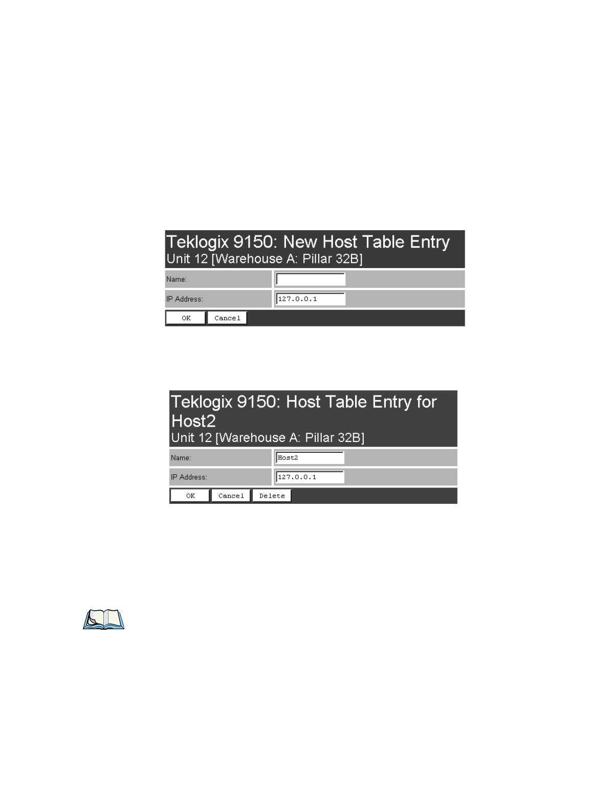
3.4.4.1 Host Table
If no external DNS server is available, the 9150 may resolve host names to IP
addresses using its internal host table. Hosts are added to the table by selecting
“Configure” beside “[#} Add Entry” in the listbox. This will open the New Host
Table Entry menu.
An existing host’s name and IP address may be edited in the Host Table Entry menu
by selecting “Configure” beside the host name in the listbox. The host may also be
deleted from the table.
Name
This is the designated name of the host.
IP Address
This is the assigned IP address for the host.
Note: The name must not contain space characters.

Chapter 3: 9150 Main Configuration
TCP/IP Parameters
38 Teklogix 9150 Wireless Gateway User Manual
3.4.4.2 Bootp
The 9150 has designated default IP addresses for itself and the Gateway. Alterna-
tively, the IP address of the 9150 can be assigned using a BOOTP Server.
The primary purpose of the Bootstrap Protocol (BOOTP) is to assign a designated
IP address to the appropriate 9150 on the network. When Employ bootp is enabled,
a request for address is automatically broadcast to all hosts on the local network.
BOOTP Servers search the bootptab files for a hardware address which matches
that of the 9150 that initiated the request for address. (Bootptab files list each
hardware address with a corresponding IP address.) The host with a matching hard-
ware address in its bootp table replies to the request, sending the appropriate IP
address to the 9150.
Employ bootp
Enable Employ bootp (√), to automatically broadcast a request for address to all
hosts on the local network.
Important: Once the 9150 is configured and rebooted the first time, the Employ
bootp parameter should be disabled, unless the 9150 obtains its IP
address from a bootp server or the system administrator intends to
update the software through bootp.
Actual Default Gateway Address
This parameter shows the Default Gateway address currently set for the 9150.
Teklogix 9150 Wireless Gateway User Manual 39
Chapter 3: 9150 Main Configuration
TCP/IP Parameters
Default Gateway Address
The Default Gateway Address is assigned by the network administrator. This
address creates an identifiable communication link between the 9150 and a network
other than the one to which the 9150 is directly wired. The acceptable values for the
Gateway IP address range from 0.0.0.0 to 239.255.255.255.
Note: Setting the Gateway IP Address to 0.0.0.0 disables this feature.
A communication link will not exist between sub-networks.
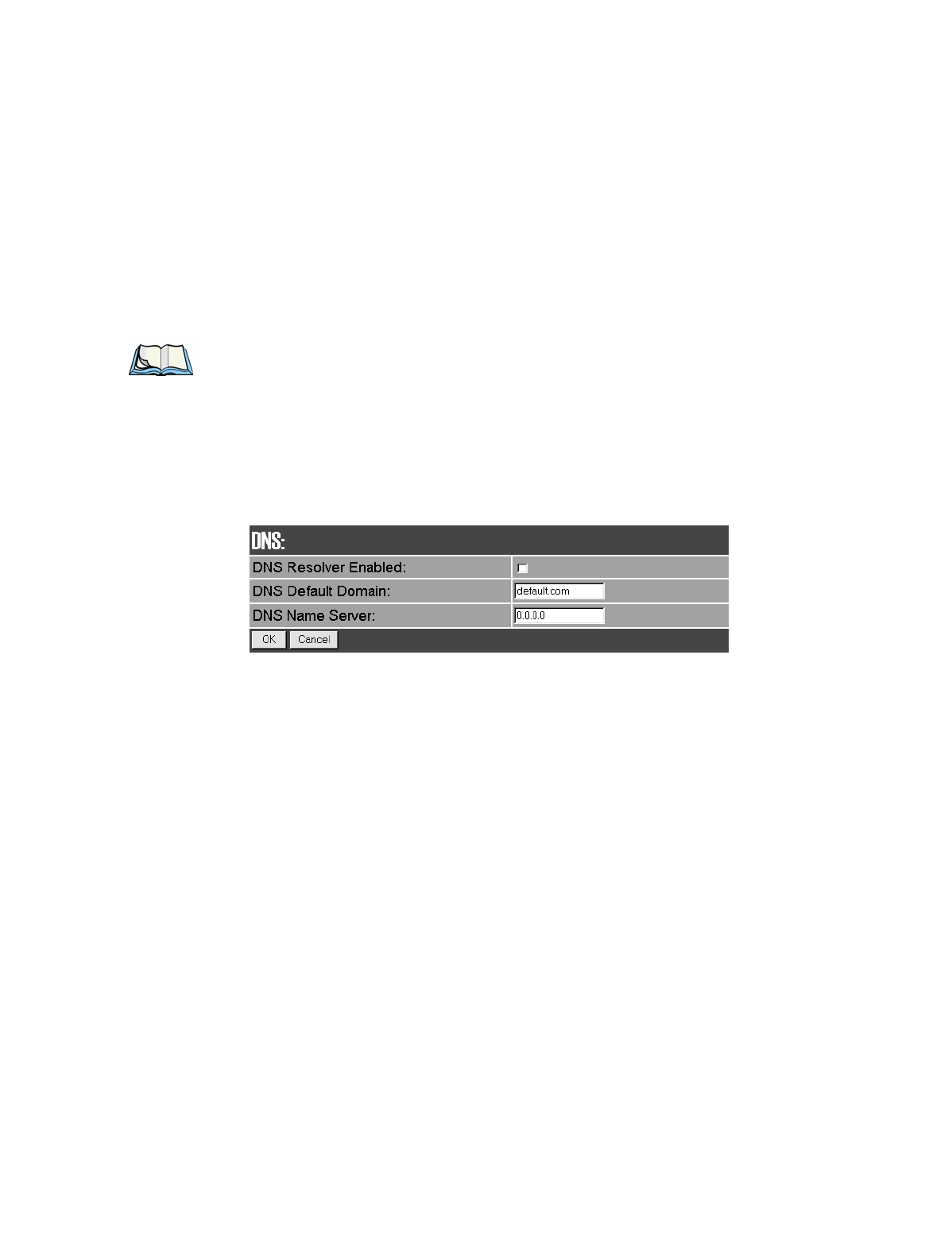
3.4.4.3 DNS
Domain Name System allows users to locate destinations on the TCP/IP network by
domain (host) name. The DNS server maintains a database of host names and their
corresponding IP addresses. For example, if the server was presented with the name
“www.teklogix.com”, it would return the IP address: “207.219.2.3”.
DNS Resolver Enabled
When this parameter is enabled (√), the 9150 will use the DNS Name Server identi-
fied by the IP address entered in the DNS Name Server parameter.
DNS Default Domain
This is the default domain name for this 9150.
DNS Name Server
This is the IP address of the designated DNS Name Server.
Chapter 3: 9150 Main Configuration
Serial Ports Parameters
40 Teklogix 9150 Wireless Gateway User Manual
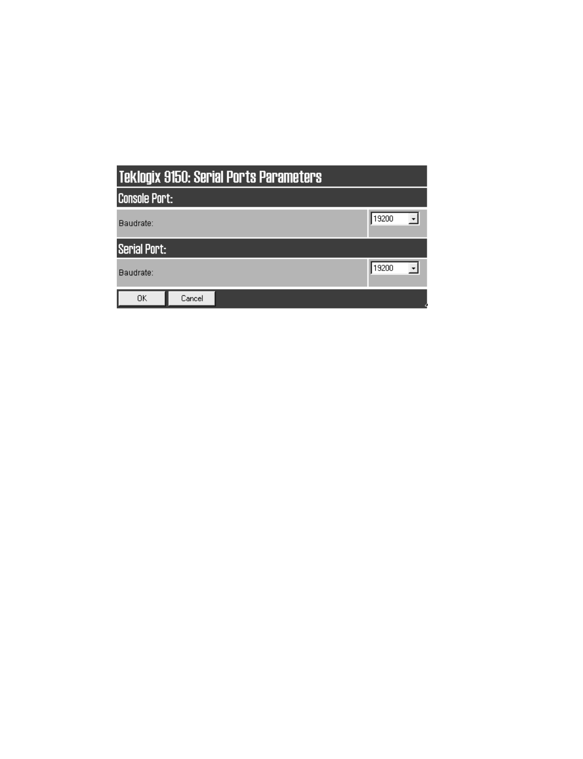
3.4.5 Serial Ports Parameters
3.4.5.1 Console Port
The default baud rate for the console port is 19.2k.
3.4.5.2 Serial Port
The default baud rate for the serial port is 19.2k.
Teklogix 9150 Wireless Gateway User Manual 41
Chapter 3: 9150 Main Configuration
Access Point/Base Station Configurations
3.5 Access Point/Base Station Configurations
The 9150 is capable of operating as a transparent bridge (access point) between the
wireless and wired networks, and also as a mini-controller or base station. For these
operations, the parameters in these pages must be set appropriately. For detailed
information on the sub-menus and to set up the 9150 as a base station, see
Chapter 4: “Base Station Configuration”. To configure an access point device,
see Chapter 6: “Access Point Configuration”. To configure the 9150 as a mini-
controller, see Chapter 5: “Mini-Controller Configuration”.
.
Chapter 3: 9150 Main Configuration
Miscellaneous Commands
42 Teklogix 9150 Wireless Gateway User Manual
3.6 Miscellaneous Commands
There are two miscellaneous commands: System Info and Reboot Unit.
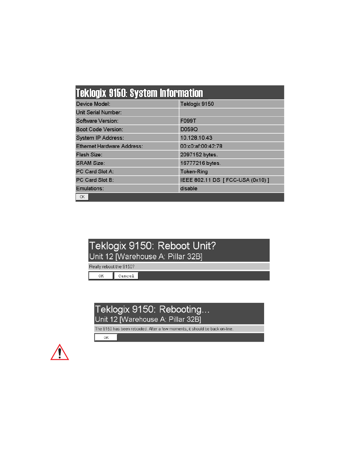
3.6.1 System Info
The System Information, hardware and software, for the 9150 Wireless Gateway
unit is detected automatically and summarized in this page. The screen is shown on
page 43.
Teklogix 9150 Wireless Gateway User Manual 43
Chapter 3: 9150 Main Configuration
Reboot Unit
3.6.2 Reboot Unit
This option opens a dialog box which allows you to remotely “warm” reboot
the 9150.
If the OK button is chosen, the 9150 will be rebooted, the LEDs will turn off
momentarily, and the following message will be received:
Important: If changing radio types in the 9150, and therefore changing the Radio
Type parameter (see page 50), the unit must be powered OFF and
ON again (“cold” rebooted). Rebooting with the Reboot Unit option
will not implement the radio parameter change.


Teklogix 9150 Wireless Gateway User Manual 45
BASE STATION CONFIGURATION 4
4.1 Overview................................47
4.2 Interfaces ................................49
4.2.1 TekLAN Parameters....................49
4.2.1.1 Radio.........................50
4.2.1.2 Wireless LAN Parameters..............52
4.2.2 Narrow Band Radio Parameters . . . . . . . . . . . . . .53
4.2.2.1 Polling Protocol Parameters . . . . . . . . . . . . .56
4.2.2.2 Radio Parameters . . . . . . . . . . . . . . . . . .59
4.2.2.3 Radio Channels . . . . . . . . . . . . . . . . . . .60
4.2.2.4 TRX7370 Radio Card Parameters . . . . . . . . . .60
4.3 Hosts..................................63
4.4 Main Host Menu............................65
4.4.1 General Host Options...................66
4.4.2 9010 / TCP/IP . . . . . . . . . . . . . . . . . . . . . . .67
4.4.2.1 Emulation Options. . . . . . . . . . . . . . . . . .67
4.4.2.2 Protocol Options And Function Key Mappings . . .68
4.4.3 9010 / Serial . . . . . . . . . . . . . . . . . . . . . . . .68
4.4.3.1 Emulation Options. . . . . . . . . . . . . . . . . .69
4.4.3.2 Protocol Options: Serial Line . . . . . . . . . . . .69
4.4.3.3 Protocol Options: 9010 Protocol . . . . . . . . . .70
4.4.3.4 Function Key Mappings . . . . . . . . . . . . . . .70
4.5 Base Stations..............................71
4.6 Radio Link Features..........................72

Teklogix 9150 Wireless Gateway User Manual 47
Chapter 4: Base Station Configuration
Overview
4.1 Overview
The 9150 Wireless Gateway can operate as a base station, facilitating communica-
tions between terminals and wireless base stations and a Teklogix 9400 or 9300
Network Controller, or 9140 Wireless Gateway (as a mini-controller) with a range
of host platforms. Alternatively, the network controller can be a host running a
Teklogix SDK (handler). The 9150 can also act as a slave base station to a 9140 on
the network. As a base station, the 9150 uses the Wireless LAN (Wlan) or Adaptive
Polling/Contention RF protocols.
Note: The 9150 main parameters should first be set up as described in Chapter 3:
“9150 Main Configuration”. For details on the RF protocols, see page 8.
Figure 4.1 9150 Base Station Configuration
9150
ETHERNET
TCP/IP
9150
9140
8055 Vehicle-Mount
9400
7030 Hand-Held
SERIAL
Wireless Gateway
Network Controller
Wireless Gateway
RF Terminal
RF Terminal
Wireless Gateway
HOST
Chapter 4: Base Station Configuration
Overview
48 Teklogix 9150 Wireless Gateway User Manual
For operation as a base station, the parameters in the Base Station Configuration
pages on the Configuration Main Menu screen should be set appropriately, as
described in the sections that follow. In addition, the appropriate radio parameters
must be applied. These are found in the Interfaces pages for TekLAN and Narrow
Band radios. See pages 49and 53, respectively.
Figure 4.2 Overview Of Base Station Configuration Menus
Teklogix 9150 Wireless Gateway User Manual 49
Chapter 4: Base Station Configuration
Interfaces
4.2 Interfaces
4.2.1 TekLAN Parameters
The pull-down menu shown for the Interfaces option in the 9150 Configuration
Main Menu page indicates which interfaces have been detected in use. Entering the
“Configure” dialog box for “Slot A: TekLAN Card”, opens the parameters page for
TekLAN, which presents both the radio and Wlan parameters.
Figure 4.3 Overview Of TekLAN Menus
Chapter 4: Base Station Configuration
TekLAN Parameters
50 Teklogix 9150 Wireless Gateway User Manual
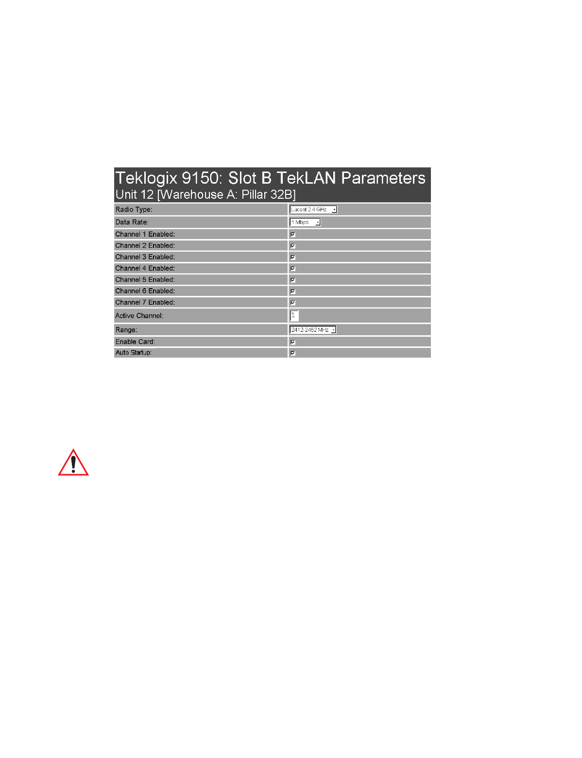
4.2.1.1 Radio
Radio Type
The type of PC radio card installed on the 9150 is dependent on your wireless net-
work. This parameter should be set to the installed radio. The radios for TekLAN are
the TekLAN 902 MHz DS Spread Spectrum, and the TekLAN 2.4 GHz DS
Spread Spectrum.
Important: If changing radio types in the 9150, DO NOT “hot swap” the PC
cards: turn the 9150 off before changing the radio. Following this,
when changing the Radio Type parameter, the unit must be powered
OFF and ON again (“cold” rebooted). Rebooting with the Reboot
Unit option will not implement the radio parameter change.
Data Rate
This parameter determines the data (baud) rate for the radio channel. This is a
decimal value in bits per second. The acceptable value for the Data Rate parameter
differs depending on the type of radio installed in the 9150.
•TekLAN 902 MHz DS SS: 122 kbps.
•TekLAN 2.4 GHz DS SS: 1 Mbps.

Teklogix 9150 Wireless Gateway User Manual 51
Chapter 4: Base Station Configuration
TekLAN Parameters
Channel n Enabled
These parameters are used to enable ( √ ) or disable a channel. The number of chan-
nels available is determined by the type of radio installed. See “PC Card Radios” on
page 145 for the number of available channels for each radio type.
Active Channel
This parameter determines the current default radio channel.
Range
The federal agencies, Industry Canada and the Federal Communications Commis-
sion in the United States, as well as other country-specific agencies world-wide,
regulate the use of radio frequencies to ensure that communication conflicts are
avoided. See “PC Card Radios” on page 145 for the assigned frequencies for each
radio type.
The Range parameter determines which channels can be enabled and is set accord-
ing to the approved frequency range in the country where the system is installed.
The TekLAN 902 MHz radio is only assigned the 902 MHz frequency. For the
TekLAN 2.4 GHz radio, the frequency range and the associated channels and
countries are assigned as follows:
Table 4.1 Frequency Range TekLAN 2.4 GHz Spread Spectrum (TRX7425)
Enable Card
This parameter enables the PC card ( √ ). The card may be disabled temporarily
when, for testing purposes, it is required that there be no radio interference.
Auto Startup
This parameter enables ( √ ) polling immediately when the 9150 is rebooted. If Auto
Startup is disabled, the 9150 will wait until polling is initialized from the network
controller. When the 9150 is operating as a Wlan base station under a network con-
troller, this parameter should be disabled.
Country Range Channels Available
For testing purposes only. 2412-2462 1 to 6
Canada, U.S., U.K. 2422-2462 2 to 6
Australia 2422-2442 2 to 4
Chapter 4: Base Station Configuration
TekLAN Parameters
52 Teklogix 9150 Wireless Gateway User Manual
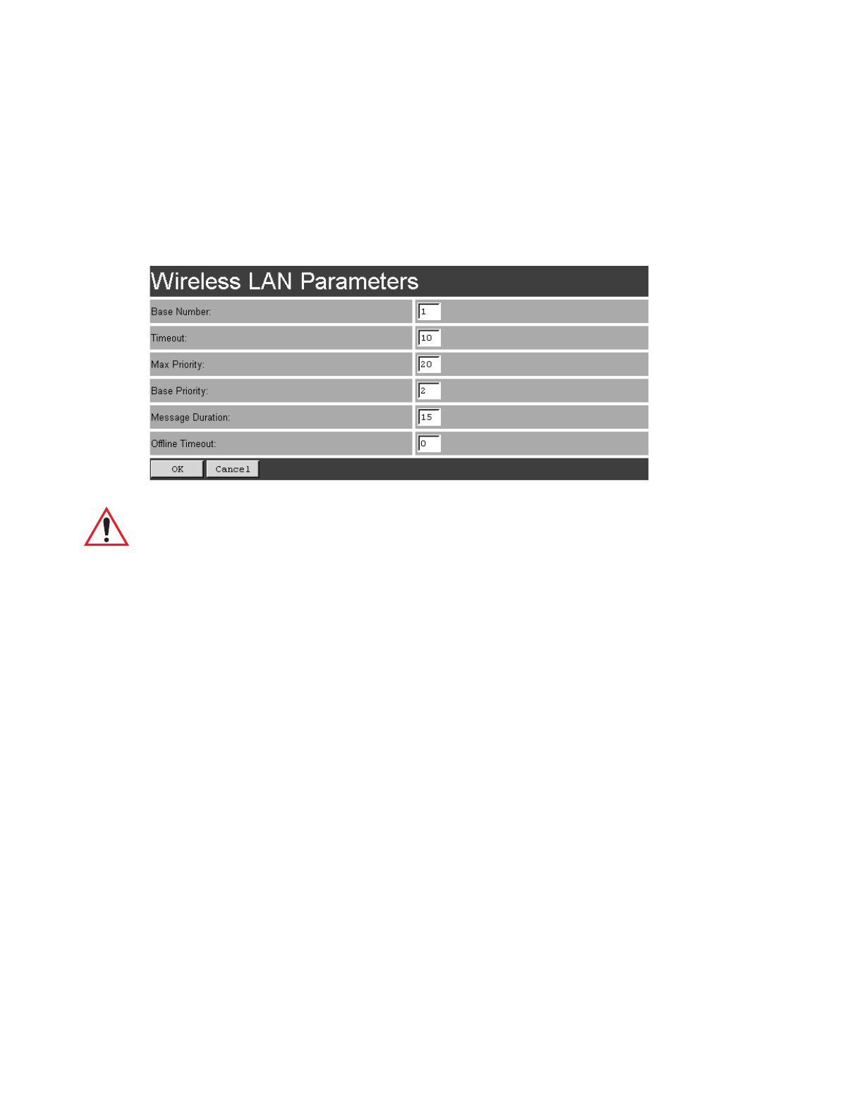
4.2.1.2 Wireless LAN Parameters
The Wlan protocol can only be used with spread spectrum radios.
Important: If your system is using the Wlan protocol, make sure that Operate in
Cellular Mode is enabled (see page 72) in the Radio Link Features
sub-menu and that cellular mode is also set on the 9400/9300
Network Controller.
Base Number
This parameter is used to assign a unique address to each base station. As the termi-
nals move from one base station to another, this address is transmitted by the base
stations to the terminals, identifying each 9150 on a multiple base station system.
The allowable range of base station numbers is 1 to 64.
Timeout
This value is used to adjust Wlan performance and should be set to 10.
Max Priority
This value is used to adjust Wlan performance and should be set to 20.

Teklogix 9150 Wireless Gateway User Manual 53
Chapter 4: Base Station Configuration
Narrow Band Radio Parameters
Base Priority (TekLAN 2.4 GHz)
The Base Priority parameter determines the number of priority transmit slots
reserved for each base station. The allowable range for this parameter is 0 to 100.
For optimal performance, this parameter should be set to a value of 2.
Message Duration (TekLAN 2.4 GHz)
This parameter controls the duration of transmit slots to optimize communications
and decrease the likelihood of collisions. A Message Duration value of 1
translates into a slot duration of 130 micro seconds. The allowable range for this
parameter is 2 to 200. For optimal performance, this parameter should be set to 15.
Offline Timeout
This parameter determines the time in minutes that a terminal is allowed to be inac-
tive before the 9150 declares it offline. An offline terminal is still considered part of
the system. Messages to offline terminals are queued at the 9150. The terminal
remains offline until it transmits any message. Values for this parameter range from
0 to 100. If the parameter is set to 0, terminals are never declared offline.
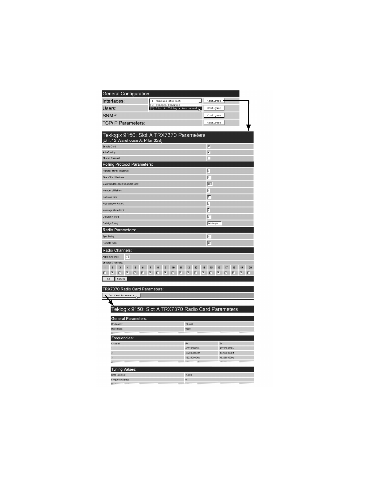
4.2.2 Narrow Band Radio Parameters
The pull-down menu shown for the Interfaces option on the 9150 Configuration
Main Menu page indicates which interfaces have been detected in use. For the selec-
tion “Slot A: Teklogix Narrowband”, entering the “Configure” dialog box will open
the parameters pages for the TRX7370 Narrow Band PC card radio. These pages list
the polling protocol and radio parameters, and show the radio card’s permanent
communications settings.
Chapter 4: Base Station Configuration
Narrow Band Radio Parameters
54 Teklogix 9150 Wireless Gateway User Manual
Figure 4.4 Overview Of Teklogix Narrow Band Menus

Teklogix 9150 Wireless Gateway User Manual 55
Chapter 4: Base Station Configuration
Narrow Band Radio Parameters
Enable Card
This parameter enables the PC card ( √ ). The card may be disabled temporarily
when, for testing purposes, it is required that there be no radio interference.
Important: If changing radio types in the 9150, DO NOT “hot swap” the PC
cards: turn the 9150 off before changing the radio.
Auto-Startup
This parameter enables ( √ ) polling immediately when the 9150 is rebooted.
If Auto Startup is disabled, the 9150 will wait until polling is initialized from the
network controller.
Shared Channel
Shared Channel is only used in Holland to accommodate government requirements.
When enabled ( √ ), it imposes timing restrictions for polling. Every 2 seconds of
polling is followed by 0.5 seconds of silence—no polling occurs.
Further, if another carrier is detected on the channel, the 9150 will cease radio trans-
missions on that channel until the path is clear.
Chapter 4: Base Station Configuration
Narrow Band Radio Parameters
56 Teklogix 9150 Wireless Gateway User Manual
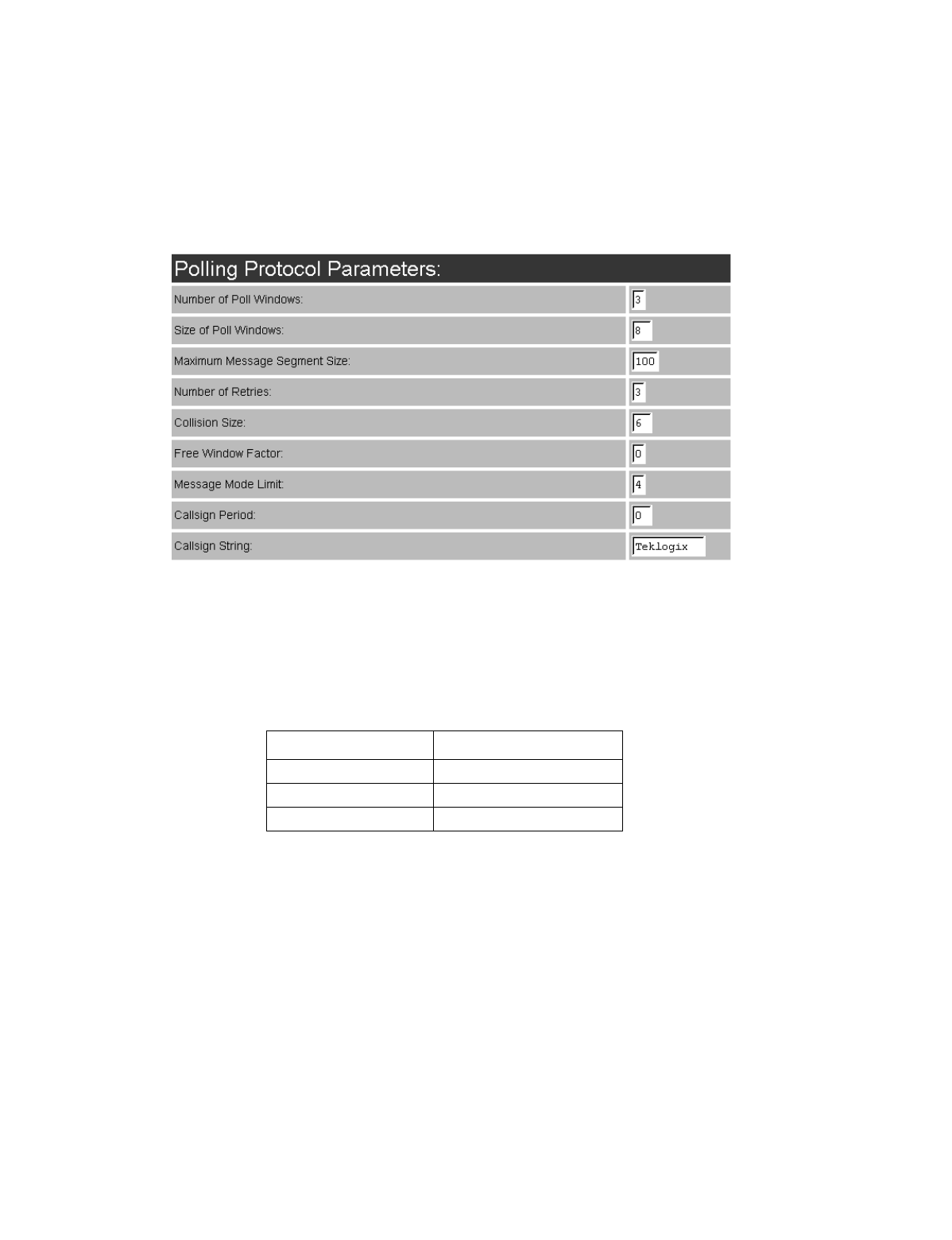
4.2.2.1 Polling Protocol Parameters
Number of Poll Windows
This parameter defines the number of poll windows the 9150 will use. The value
assigned to this parameter is dependent on the number of terminals and the radio
link protocol used.
Table 4.2 indicates how the value assigned to the Number of Poll Windows parame-
ter is determined.
Table 4.2 Number Of Poll Windows Cellular Protocol
Size of Poll Windows
The value assigned to this parameter determines the largest message that can be
passed between the 9150 and the terminal in a normal poll window. The window
size can be adjusted to accommodate anywhere from 4 to 32 characters.
Number of Terminals Minimum # of Windows
1-16 2
17-81 3
82-256 4

Teklogix 9150 Wireless Gateway User Manual 57
Chapter 4: Base Station Configuration
Narrow Band Radio Parameters
Larger windows increase the polling period and can increase the response time.
Smaller windows increase the number of message and long message polls, and can
also increase the response time.
Important: In “Cellular” mode, the minimum value for this parameter is 8.
Maximum Message Segment Size
This parameter determines the largest single message that can be passed to a
terminal in message mode or from a terminal in long message mode. In a 9150 base
station, the value entered in this parameter must be greater than or equal to the value
entered in the network controller or 9150 mini-controller. The range of this parame-
ter is between 32 and 116 characters. (Longer messages are broken into several
packets.) The default value is 100.
Number of Retries
This parameter determines how many times the 9150 attempts to resend a message
if an acknowledgement is not received from the terminal. (These retries do not
necessarily occur in consecutive polls because incomplete messages are returned to
the bottom of the message queue.) After all retries have been exhausted, the terminal
is declared “offline”. The 9150 does not transmit any messages to the terminal until
the terminal declares itself “online”. The allowable values range from 1 to 7.
Collision Size
This parameter reduces the probability that random noise on the radio link will be
interpreted as a collision between terminals. Response time increases when the 9150
resolves collisions unnecessarily.
Collision Size places an upper limit on the number of characters that are received
prior to the receipt of an error message (CRC, CD lost, etc.). If eight is the value of
this parameter, eight or less characters followed by an error message appearing over
the radio link are considered noise. If there are more than eight characters, it is con-
sidered a collision. Acceptable values range from 3 to 15.
Free Window Factor
The value entered in this parameter determines if “free window mode” will be used.
In free window mode, all terminals transmit in the free poll window instead of the
window to which they are normally assigned.

Chapter 4: Base Station Configuration
Narrow Band Radio Parameters
58 Teklogix 9150 Wireless Gateway User Manual
Entering a value of 0 (zero) in this parameter disables free window mode. Increas-
ing the value of this parameter increases the likelihood of a message being transmit-
ted in the free window.
Message Mode Limit
This parameter defines an upper limit to the number of messages that must be
queued for transmission before message mode polling starts. Accepted values range
from 0 to 7, where 0 disables message mode.
Note: The number of terminals and past events are also part of the algorithm
that determines whether or not to start message mode.
Callsign Period
A call sign is periodically transmitted as an audible Morse code signal. This
parameter specifies the interval in minutes between call sign transmissions.
Acceptable values range from 0 to 60. The federal agencies, Industry Canada and
the Federal Communications Commission in the United States, require that each
system transmit its own identification call sign every 15 minutes.
In countries where a call sign is not required, setting this parameter to 0 prevents the
transmission of any call signs, allowing for shorter poll time-outs in terminals and
faster channel switching.
Callsign String
This string can be a maximum of 10 characters long. All characters are either
numbers or letters. The prefix “DE” (from) is added to the beginning of the transmit-
ted call sign.

Teklogix 9150 Wireless Gateway User Manual 59
Chapter 4: Base Station Configuration
Narrow Band Radio Parameters
4.2.2.2 Radio Parameters
Sync Delay
Important: This parameter should not be changed from its factory setting
without a clear understanding of the timing of the radio protocol.
Sync Delay specifies the delay between the time of the base station transmission and
the first response window, measured in milliseconds. The value assigned to this
parameter must be compatible with other base stations and terminals in the system.
The default setting of 22 is based on the requirements of a 2 level modulation
narrow band radio, operating at 9600 baud.
Remote Txon
Remote Txon accommodates the turn on time of the radio in the base station.
It specifies the number of fill characters sent to the radio before real data is output.
Since this parameter is based on character times, the number is dependent on the
radio link baud rate. When the baud rate is changed, this parameter automatically
changes to the correct value.
The value assigned to the Remote Txon parameter must be consistent across all
terminals and base station equipment.
Important: This parameter should not be changed from its factory setting
without an understanding of the timing of the radio protocol.
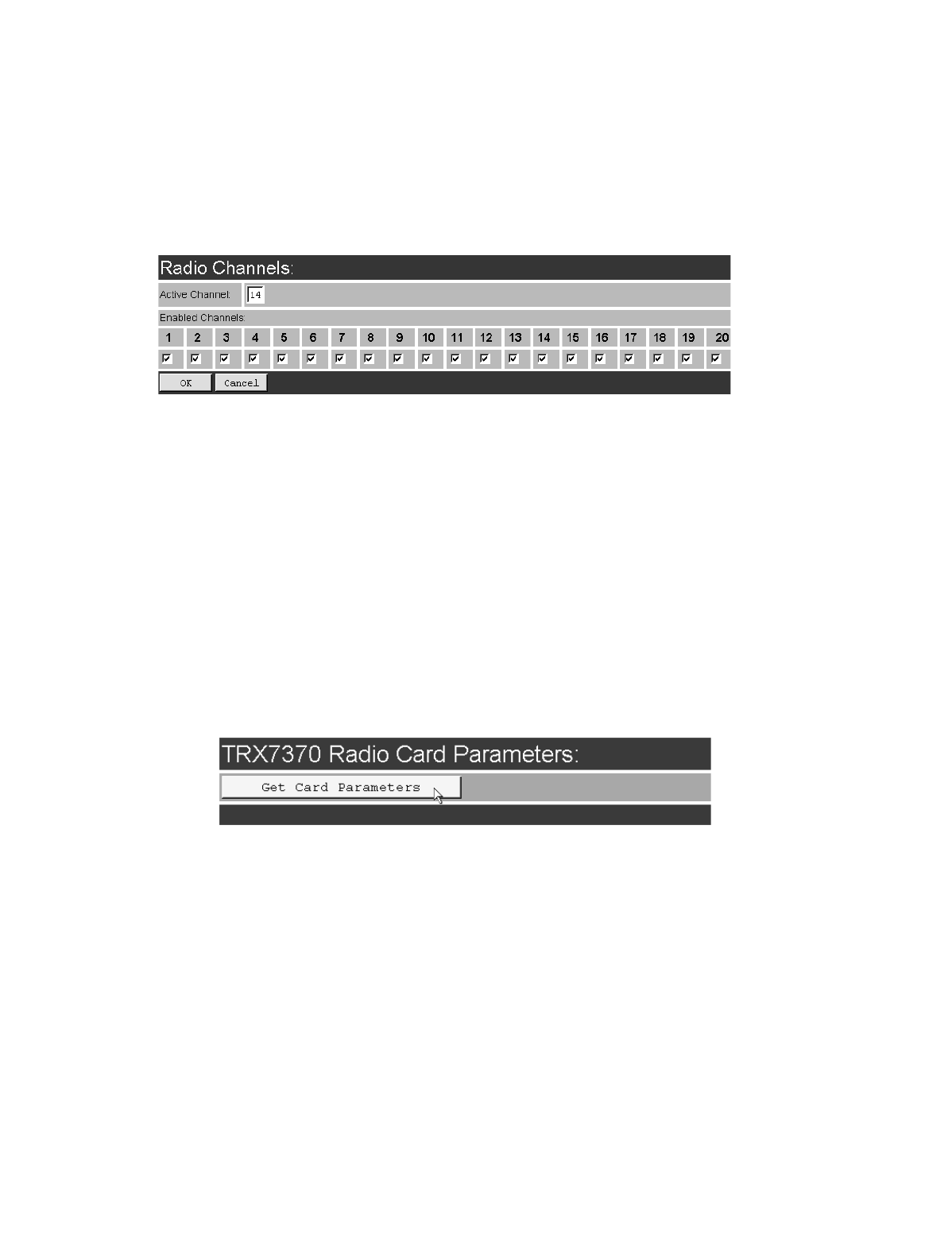
Chapter 4: Base Station Configuration
Narrow Band Radio Parameters
60 Teklogix 9150 Wireless Gateway User Manual
4.2.2.3 Radio Channels
Active Channel
This parameter determines the operating radio channel of the 9150. The channel
selected must be an enabled channel. Refer to Enabled Channels, below, for details.
Enabled Channels
This parameter is used to enable ( √ ) or disable up to 20 channels – the maximum
number of channels supported by the TRX7370 radio. Enabling a channel allows the
channel to be set to an operating channel (Active Channel) and also makes the
channel available for channel searching. If, for example, the operating channel is 1
and all other channels are enabled, terminals may roam through all 20 channels.
Note that the Enabled Channels menu only displays channels that have been config-
ured with frequencies. See page 62 for the list of associated frequencies.
4.2.2.4 TRX7370 Radio Card Parameters
Entering the “Get Card Parameters” dialog box will open the list of General, Fre-
quencies, and Tuning Values parameters for the TRX7370 Narrow Band PC card
radio. These manufacturer’s settings are not configurable. The settings are shown on
pages 62 and 63.

Teklogix 9150 Wireless Gateway User Manual 61
Chapter 4: Base Station Configuration
Narrow Band Radio Parameters
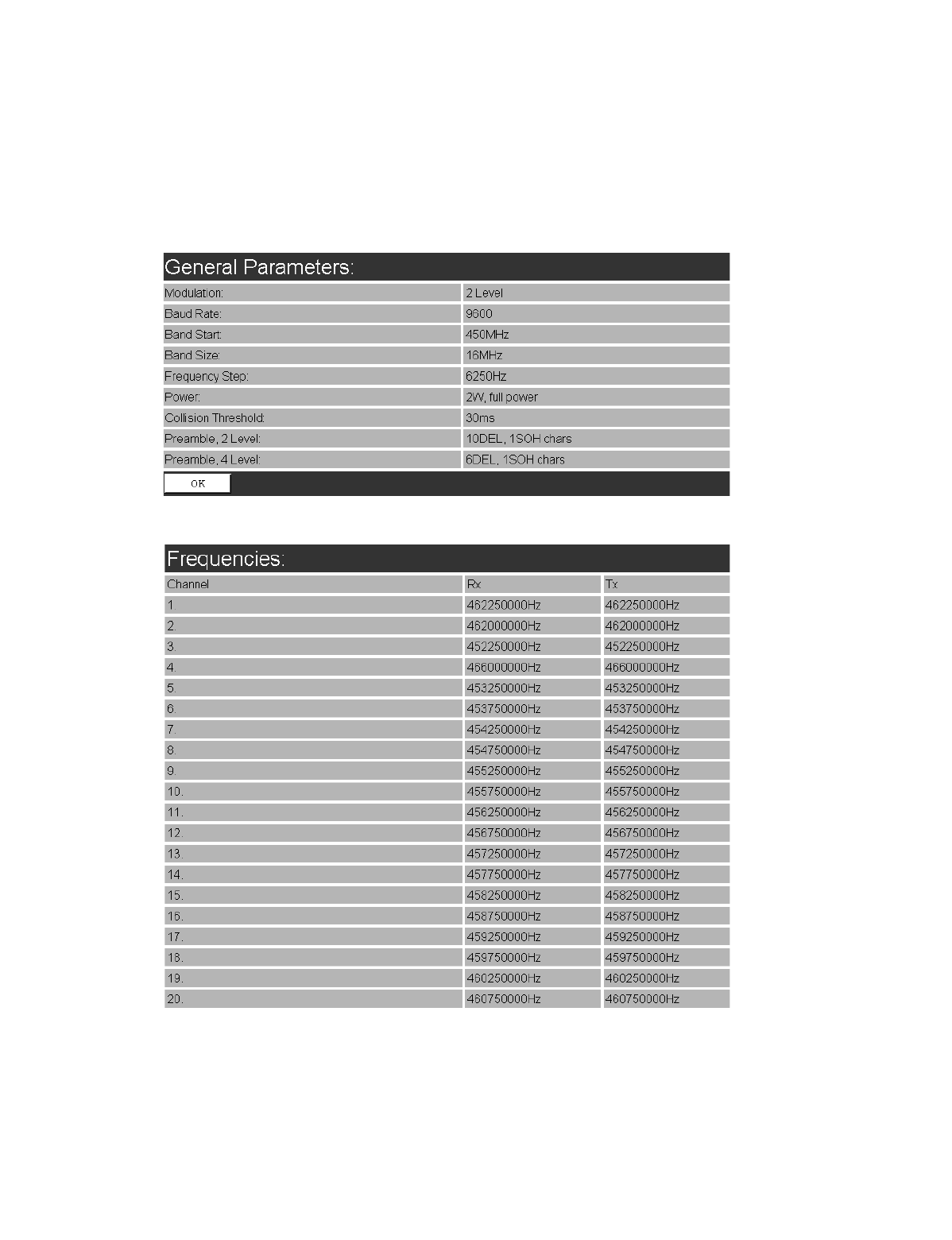
Chapter 4: Base Station Configuration
Narrow Band Radio Parameters
62 Teklogix 9150 Wireless Gateway User Manual
General Parameters
Frequencies
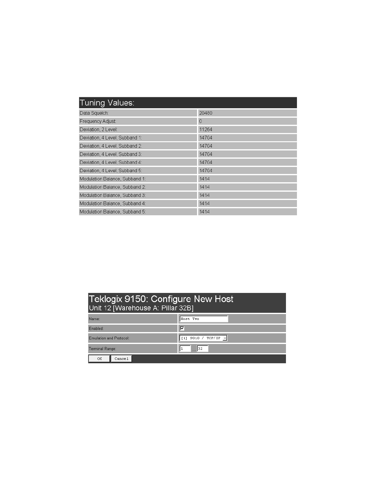
Teklogix 9150 Wireless Gateway User Manual 63
Chapter 4: Base Station Configuration
Hosts
Tuning Values
4.3 Hosts
The drop-down menu in this option shows the host names present on the system. Up
to six hosts can be supported. A “host” must be configured for each master network
controller, TSDK host, or master base station that communicates with the 9150.
Opening the “Configure” dialog box for a selected host lists the parameters that can
be modified or deleted for that host. New hosts can be added by selecting “[#]
Create New” in the drop-down menu before entering the “Configure” dialog box.

Chapter 4: Base Station Configuration
Hosts
64 Teklogix 9150 Wireless Gateway User Manual
Name
This parameter indicates the assigned host name. The host name also appears on the
RF terminal when switching between hosts in a multiple-host environment.
Note: The name must not contain space characters.
Enabled
The Enabled option must be turned on ( √ ) for terminals to communicate with
this host.
Emulation and Protocol
This drop-down menu provides a list of host emulations and communication proto-
cols supported by the 9150. The supported emulations with their respective
protocols are:
•9010/ TCP/IP (See page 67 for configuration parameters).
•9010/ Serial (See pages 68 to 70 for configuration parameters).
•3274/Telnet (See pages 84 to 98 for Configuration Parameters).
•5250/Telnet (See pages 99 to 112 for Configuration Parameters).
•ANSI/Telnet (See pages 113 to 121 for Configuration Parameters).
When the 9150 acts as a base station, it uses the 9010 protocol (a proprietary
protocol developed by Teklogix) with either a TCP/IP or serial connection to com-
municate with a 9400 or 9300 Network Controller, or a host using a Teklogix
Software Development Kit (TSDK). This protocol uses TESS (Teklogix Screen
Subsystem) or ANSI data streams to communicate with terminals. For detailed
information, please refer to the appropriate Teklogix User Manual for: 9400 or 9300
Network Controller, TSDK, TESS or ANSI.
When the 9150 acts as a mini-controller, it uses the 3274 and 5250 emulation
protocols to communicate with IBM hosts, or the ANSI emulation protocol to com-
municate with ANSI hosts. For detailed information on configuring the 9150 as a
mini-controller, please refer to Chapter 5: “Mini-Controller Configuration”.
Protocols are the methods by which terminals communicate with host computers
over various physical media such as Ethernet, Token Ring, and serial connections, as
well as radio-link connections. The 9150 supports the TCP/IP protocol.
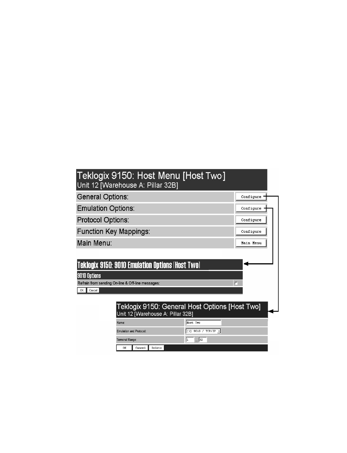
Teklogix 9150 Wireless Gateway User Manual 65
Chapter 4: Base Station Configuration
Main Host Menu
Terminal Range
The values entered in this parameter designate the first and last terminals in the
range of terminals that will communicate with the host. These terminal numbers are
mapped to this particular host.
4.4 Main Host Menu
When you choose an existing host from the Hosts listbox and then select the Config-
ure button, the 9150 displays the Host Menu.
Figure 4.5 Overview Of Host Menus For 9010 / TCP/IP
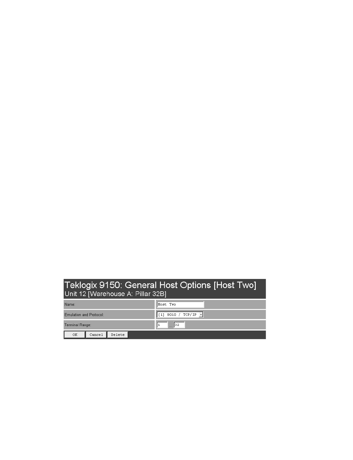
Chapter 4: Base Station Configuration
General Host Options
66 Teklogix 9150 Wireless Gateway User Manual
The Host Menu has four configuration sub-menus:
“General Host Options”
When you select this sub-menu, the 9150 displays the General Options page
for the host.
“Emulation Options”
When you select this sub-menu, the 9150 displays the Emulation Options
page for the host. This page may vary depending on the type of emulation and
protocol selected for the host.
“Protocol Options” (not applicable to 9010/TCP/IP emulation)
When you select this sub-menu, the 9150 displays the Protocol Options page
for the host. This page may vary depending on the type of emulation and pro-
tocol selected for the host.
“Function Key Mappings” (3274, 5250, ANSI emulations only)
When you select this sub-menu, the 9150 displays the Function Key Mapping
page for the host. This page may vary depending on the type of emulation and
protocol selected for the host.
There is also a Main Menu button. When you select this button, the 9150 displays
the Configuration Main Menu (see page 48).
4.4.1 General Host Options
In this screen, you can select general options for the host connection. The host con-
nection may also be deleted.
Name
This parameter allows you to enter a name for the new host.

Teklogix 9150 Wireless Gateway User Manual 67
Chapter 4: Base Station Configuration
9010 / TCP/IP
Emulation and Protocol
This parameter allows you to select the emulation and protocol to be used for the
connection to this host. As a base station, the 9150 can use either 9010/ TCP/IP or
9010/SERIAL, depending on the connection to the network controller or host.
Terminal Range
This parameter allows you to specify the range of terminals which will communi-
cate with this host. The left-hand textbox contains the lowest terminal number which
is allowed to communicate with the host; the right-hand textbox contains the highest
terminal number. Terminal numbers may range from 1 to 3840.
4.4.2 9010 / TCP/IP
4.4.2.1 Emulation Options
Refrain from sending On-line & Off-line messages
If this parameter is enabled ( √ ), the 9150 base station does not notify the host if
the status of a terminal changes between offline and online. If this parameter is
disabled, the 9150 does notify the host regarding any terminal status changes.
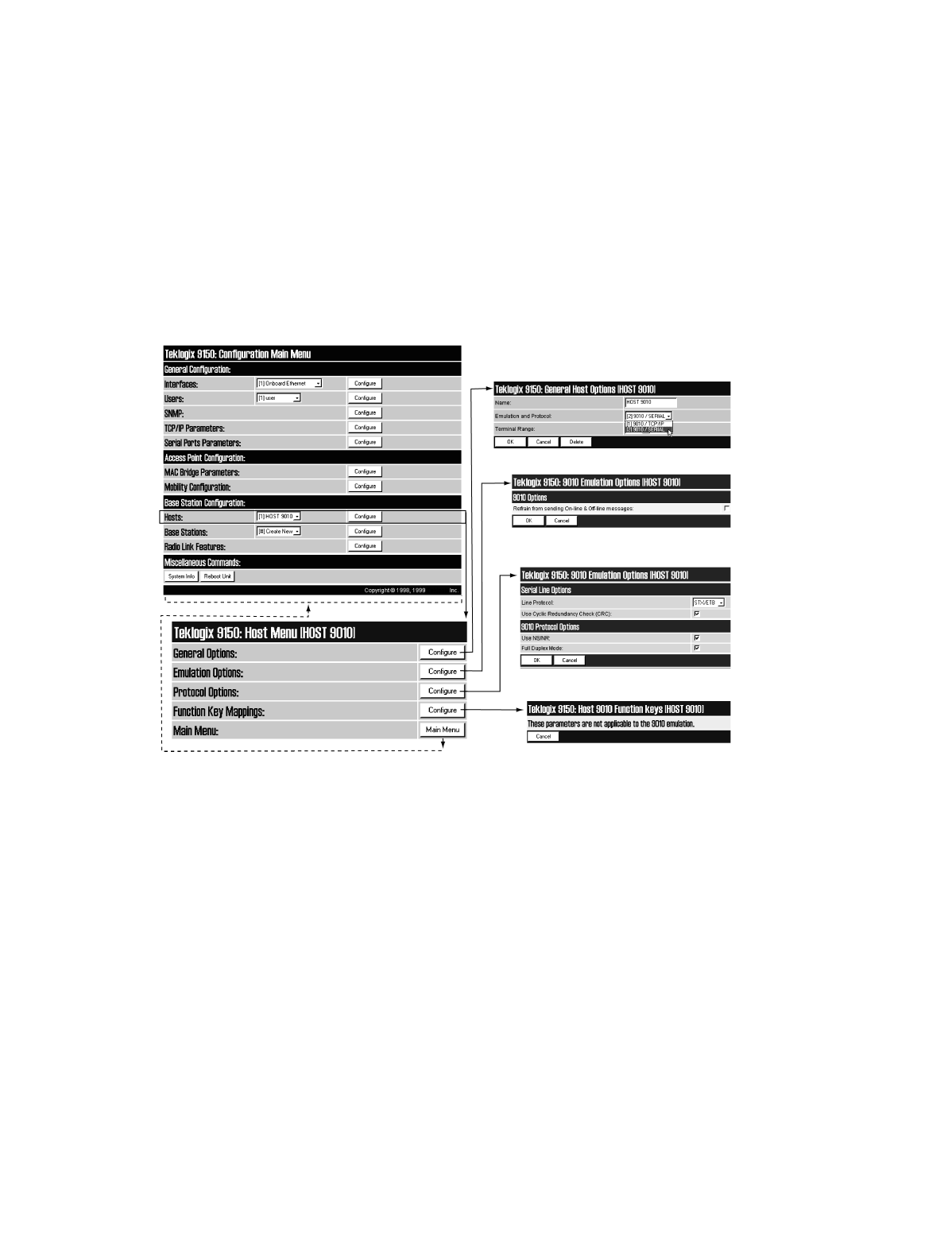
Chapter 4: Base Station Configuration
9010 / Serial
68 Teklogix 9150 Wireless Gateway User Manual
4.4.2.2 Protocol Options And Function Key Mappings
These parameters are not applicable to the 9010 / TCP/IP emulation.
4.4.3 9010 / Serial
Figure 4.6 Overview Of Host Menus For 9010 / Serial

Teklogix 9150 Wireless Gateway User Manual 69
Chapter 4: Base Station Configuration
9010 / Serial
4.4.3.1 Emulation Options
Refrain from sending On-line & Off-line messages
If this parameter is enabled ( √ ), the 9150 base station does not notify the host if
the status of a terminal changes between offline and online. If this parameter is
disabled, the 9150 does notify the host regarding any terminal status changes.
4.4.3.2 Protocol Options: Serial Line
Line Protocol
This listbox specifies the serial line protocol used on this host connection.
Chapter 4: Base Station Configuration
9010 / Serial
70 Teklogix 9150 Wireless Gateway User Manual
The three available choices are STX/ETB, LF/CR, and DEL/LF. Each of these
three choices specifies the start and end characters that delimit the start and end of
data on the serial link to the host. These characters are:
Note: For communication to Teklogix handlers or SDKs, always use STX/ETB.
LF/CR and DEL/LF are used in third-party handlers.
The default setting is STX/ETB.
Use Cyclic Redundancy Check (CRC)
If this parameter is enabled ( √ ), the 9150 base station uses a CRC checksum on the
data sent over the serial line to the host.
4.4.3.3 Protocol Options: 9010 Protocol
Use NS/NR
If this parameter is enabled ( √ ), the 9150 base station uses NS/NR protocol for this
serial host connection.
Note: Only use NS/NR with the STX/ETB protocol. Teklogix recommends that
this be enabled when possible.
Full Duplex Mode
If this parameter is enabled ( √ ), the 9150 base station uses full-duplex communica-
tion on this serial host connection.
4.4.3.4 Function Key Mappings
These parameters are not applicable to the 9010/Serial emulation.
Character Code Meaning Hex Value
STX Start of Text 01
ETB End of Text Block 17
LF Line Feed 0A
CR Carriage Return 0D
DEL Delete 7F
Table 4.3 Serial Line Protocol Character Codes
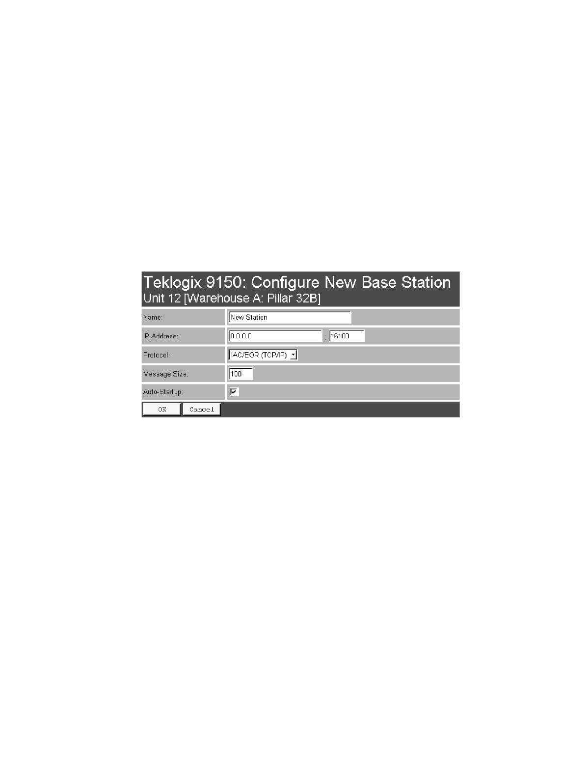
Teklogix 9150 Wireless Gateway User Manual 71
Chapter 4: Base Station Configuration
Base Stations
4.5 Base Stations
These options and parameters allow you to configure the 9150 as a master base
station connected to up to 32 slave 9150 and 9140 base stations over an Ethernet or
Token Ring network. The master 9150 is connected to a 9400 or 9300 Network
Controller, or up to six hosts running TSDK (Teklogix Software Development Kit).
From the Base Stations option under Base Station Configuration (see Figure 4.2 on
page 48), entering “Configure” will open the “Configure New Base Station” page,
which will enable you to add a new slave base station to the system or change the
parameters on an existing slave base station.
Name
The name entered in this parameter is used as an alternate way of identifying the
IP address of a slave base station.
IP Address
This parameter provides the corresponding IP address for the slave base station.
The IP Address must be a unique value so that each slave base station can be iden-
tified on the network. The acceptable value ranges from 0.0.0.0 to 239.255.255.255.
The default value for the IP port is 16100.
Protocol
IAC/EOR (TCP/IP) is the default protocol for the Ethernet or Token Ring connection.
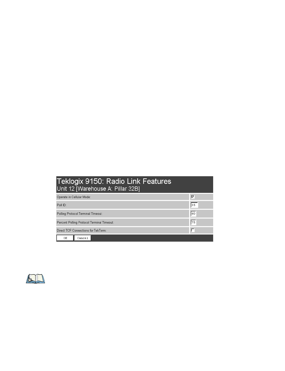
Chapter 4: Base Station Configuration
Radio Link Features
72 Teklogix 9150 Wireless Gateway User Manual
Message Size
Message Size determines the largest single message that can be passed to a
terminal. The range of this parameter is between 32 and 380 characters. (Longer
messages are broken into several packets.) For polling protocol base stations, the
upper limit is 116.
Auto-Startup
When this parameter is enabled ( √ ), the slave base stations will start polling when
the master 9150 boots up. When Auto-Startup is disabled, the base stations will not
start polling until they receive a start polling command from the host.
4.6 Radio Link Features
From the Radio Link Features option under Base Station Configuration (see
Figure 4.2 on page 48), entering “Configure” will open the “Radio Link Features”
page for the polling and cellular parameters.
Operate in Cellular Mode
To operate as a Wlan base station, this parameter should be enabled ( √ ). For
further information see “Wlan Protocol” on page 8.
Note: The 9400 or 9300 Network Controller must also be set to cellular mode.

Teklogix 9150 Wireless Gateway User Manual 73
Chapter 4: Base Station Configuration
Radio Link Features
Poll ID
In Wlan protocol, this is a unique identifying number set only in a 9150 master base
station, 9150 mini-controller or a network controller, which is used in the poll
header when polling terminals. Poll ID is set by Teklogix personnel.
In Adaptive Polling/Contention protocol for narrow band radios, Poll ID is used to
assign a unique address to each base station. As the terminals move from one base
station to another, this address is transmitted by the base stations to the terminals,
identifying each 9150 in a multiple base station system.
Polling Protocol Terminal Timeout
This parameter determines the time in minutes that a terminal can be inactive before
the 9150 declares it offline. Before this happens, the terminal will be declared
offline by the Percent Polling Protocol Terminal Timeout parameter (see below).
After the terminal is removed from the system, it will need to re-initialize in order to
communicate with the 9150. This parameter reduces the overhead on the radio link
caused when terminals which are not communicating are supported. The allowable
values range from 1 to 240.
Note: This parameter is not relevant for Wlan.
Percent Polling Protocol Terminal Timeout
This parameter determines the time that a terminal is allowed to be inactive before
the 9150 declares it offline. This time is expressed as a percentage of the Polling
Protocol Terminal Timeout parameter, above. For example, if the Polling Protocol
Terminal Timeout is 60, and this parameter is set to 75%, then the timeout would be
60 min x 75% = 45 minutes. An offline terminal is still considered part of the
system. Messages to offline terminals are queued at the 9150. The terminal remains
offline until it transmits an online message. Values for this parameter range from 50
to 90.
Direct TCP Connections for TekTerm
Enabling this parameter allows the TekTerm program resident in Teklogix
terminals to connect directly to the 9150, when it is acting as a base station to
a host via TCP/IP.


Teklogix 9150 Wireless Gateway User Manual 75
MINI-CONTROLLER CONFIGURATION 5
5.1 Overview.............................77
5.2 Hosts...............................80
5.3 Main Host Menu.........................82
5.3.1 General Options...................83
5.3.2 9010 Emulations . . . . . . . . . . . . . . . . . . . 84
5.3.3 3274/Telnet. . . . . . . . . . . . . . . . . . . . . . 84
5.3.3.1 Emulation Options. . . . . . . . . . . . . . . 84
5.3.3.2 Protocol Options. . . . . . . . . . . . . . . . 95
5.3.3.3 Function Key Mappings . . . . . . . . . . . . 98
5.3.4 5250/Telnet. . . . . . . . . . . . . . . . . . . . . . 99
5.3.4.1 Emulation Options. . . . . . . . . . . . . . . 99
5.3.4.2 Protocol Options. . . . . . . . . . . . . . . 110
5.3.4.3 Function Key Mappings . . . . . . . . . . . 112
5.3.5 ANSI/Telnet....................113
5.3.5.1 Emulation Options. . . . . . . . . . . . . . 113
5.3.5.2 Protocol Options. . . . . . . . . . . . . . . 116
5.3.5.3 Function Key Mappings . . . . . . . . . . . 121


Teklogix 9150 Wireless Gateway User Manual 77
Chapter 5: Mini-Controller Configuration
Overview
5.1 Overview
The network controller in a Teklogix system performs a number of important tasks.
One of these tasks is emulation: the translation of data between the protocol of the
host computer and the protocol used by Teklogix terminals.
The data which is sent from a host computer to a terminal to provide its display, and
returned to the host as a result of operations at the terminal, is called a data stream.
Host computers can provide data streams of various types to their terminals.
Teklogix terminals can directly accept only two types of data stream: TESS and
ANSI. TESS (Teklogix Screen Subsystem) is the proprietary data stream used by
Teklogix terminals. ANSI data streams are a standard type of data stream used by
wired ANSI terminals. Other types of data stream provided by the host must be
converted into TESS or ANSI before Teklogix terminals can work with them. This
translation is done by emulation software in a network controller.
The 9150 is equipped with emulation capabilities, allowing it to act as a mini-
controller. When a 9150 is configured as a mini-controller, Teklogix terminals can
emulate an ANSI, 5250 or 3274 terminal via a 9150 rather than through a 9400/9300
Network Controller.
Important: 9150s acting as mini-controllers are designed for small, low-
transaction sites. A 9400/9300 Network Controller is required for
systems that support more than 50 terminals.
Acting as a mini-controller, the 9150 can support up to 32 additional networked base
stations and up to 50 terminals. A 9150 mini-controller can also manage wireless
LAN configurations.
A 9150 configured as a mini-controller can support the following emulations:
•5250 emulation using TCP/IP over an Ethernet or Token Ring LAN.
•3274 emulation using TCP/IP over an Ethernet or Token Ring LAN.
•ANSI emulation using TCP/IP over an Ethernet or Token Ring LAN.
Note: The 9150 main parameters should first be set up as described in Chapter 3:
“9150 Main Configuration”.
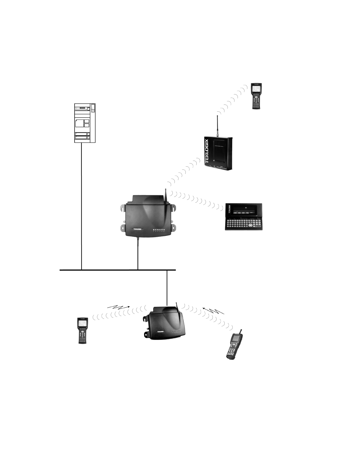
Chapter 5: Mini-Controller Configuration
Overview
78 Teklogix 9150 Wireless Gateway User Manual
Figure 5.1 9150 Mini-Controller Configuration
Hand-Held
RF Terminal
7035
Hand-Held
RF Terminal
Mini-Controller
9150 Wireless Gateway
Base Station and Access Point
9150 Wireless Gateway
%!
7030 Hand-Held
RF Terminal
802.11 / 2.4 GHz
902 MHz
ETHERNET
TCP/IP
9140
8055 Vehicle-Mount
RF Terminal
Wireless Gateway
HOST
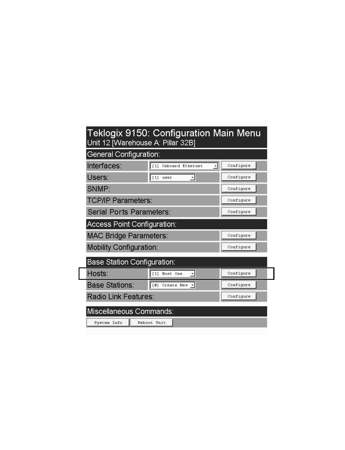
Teklogix 9150 Wireless Gateway User Manual 79
Chapter 5: Mini-Controller Configuration
Overview
For operation as a mini-controller, the parameters in the Hosts pages under Base
Station Configuration should be set appropriately. The Hosts options are found on
the Configuration Main Menu page. For information on configuring radio protocol
parameters, please refer to “Radio Link Features” on page 72.

Chapter 5: Mini-Controller Configuration
Hosts
80 Teklogix 9150 Wireless Gateway User Manual
5.2 Hosts
The drop-down menu in this option shows the host names present on the system. Up
to six hosts can be supported. A “host” must be configured for each host that com-
municates with the 9150 mini-controller. Opening the Configure dialog box for a
selected host lists the parameters that can be modified or deleted for that host. New
hosts can be added by selecting “[#] Create New” in the drop-down menu before
entering the Configure dialog box.
Name
This parameter indicates the assigned host name. The host name also appears on the
RF terminal when switching between hosts in a multiple-host environment.
Enabled
The Enabled option must be turned on ( √ ) for terminals to communicate with
this host.
Emulation and Protocol
This drop-down menu provides a list of host emulations and communication proto-
cols supported by the 9150. Working with Teklogix terminals and base stations, the
9150 can emulate IBM 3278-2, 5251-11, and 5555-B01 terminals, as well as
ANSI terminals.
Protocols are the methods by which terminals communicate with host computers
over various physical media such as Ethernet, Token Ring, and serial connections, as
well as radio-link connections. The 9150 supports the TCP/IP protocol.

Teklogix 9150 Wireless Gateway User Manual 81
Chapter 5: Mini-Controller Configuration
Hosts
The supported emulations with their respective protocols are:
•9010/ TCP/IP or Serial (See page 84 for Configuration Parameters).
•3274/Telnet (See pages 84 to 98 for Configuration Parameters).
•5250/Telnet (See pages 99 to 112 for Configuration Parameters).
•ANSI/Telnet (See pages 113 to 121 for Configuration Parameters).
When the 9150 acts as a base station, it uses the 9010 emulation (a proprietary asyn-
chronous protocol developed by Teklogix) to communicate with a 9300 Network
Controller or a host using a Teklogix Software Development Kit (TSDK). For
detailed information on configuring the 9150 as a base station, please refer to
Chapter 4: “Base Station Configuration”.
When the 9150 acts as a mini-controller, it uses the 3274 and 5250 emulation
protocols to communicate with IBM hosts, or the ANSI emulation protocol to com-
municate with ANSI terminals.
Terminal Range
The values entered in this parameter designate the first and last terminals in the
range of terminals that will communicate with the host. These terminal numbers are
mapped to this particular host. Terminal numbers may range from 1 to 50.
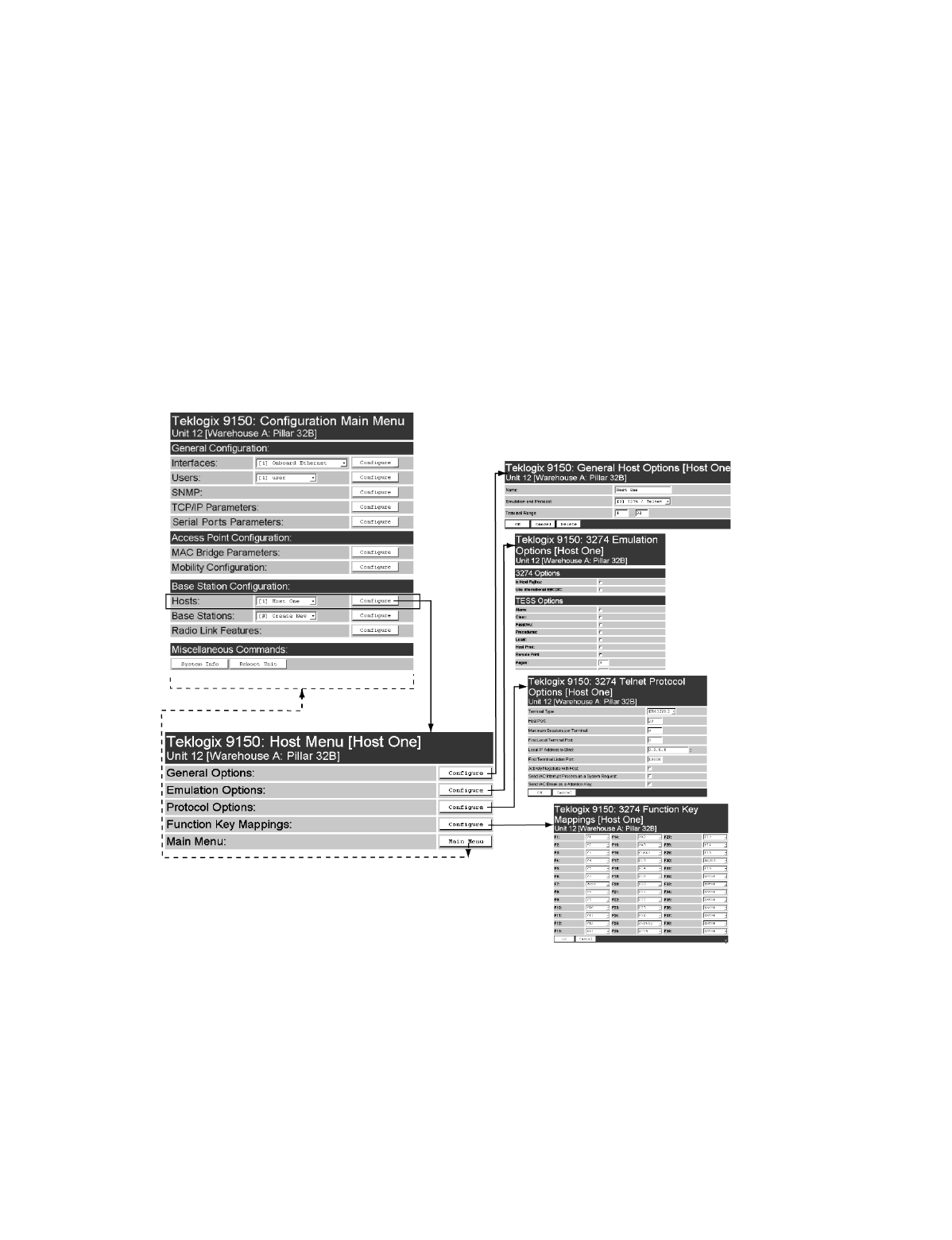
Chapter 5: Mini-Controller Configuration
Main Host Menu
82 Teklogix 9150 Wireless Gateway User Manual
5.3 Main Host Menu
When you choose an existing host name from the Hosts listbox and then select the
Configure button, the 9150 displays the Host Menu. The Host Menu presents the
options for four sub-menus: General Host Options, Emulation Options, Protocol
Options, and Function Key Mappings. There is also a Main Menu button. When
you select this button, the 9150 displays the Configuration Main Menu page
(see page 79 for an enlarged illustration).
Figure 5.2 Overview Of Host Menus
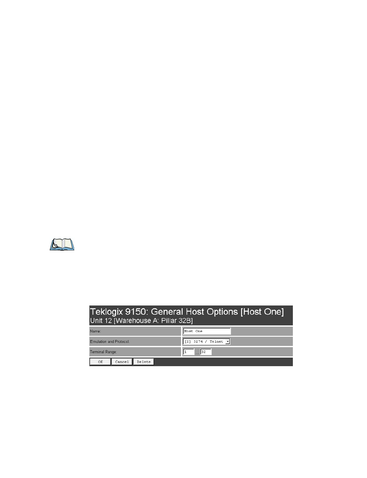
Teklogix 9150 Wireless Gateway User Manual 83
Chapter 5: Mini-Controller Configuration
General Options
As illustrated in Figure 5.2 on page 82, the four configuration sub-menus display the
following options:
“General Options”
When you select this sub-menu, the 9150 displays the General Options page for
the host.
“Emulation Options”
When you select this sub-menu, the 9150 displays the Emulation Options page
for the host. This page may vary depending on the type of emulation and proto-
col selected for the host.
“Protocol Options”
When you select this sub-menu, the 9150 displays the Protocol Options page
for the host. This page may vary depending on the type of emulation and proto-
col selected for the host.
“Function Key Mappings”
When you select this sub-menu, the 9150 displays the Function Key Mappings
page for the host. This page may vary depending on the type of emulation and
protocol selected for the host.
Note: The Function Key Mappings parameters are not applicable to either of
the 9010 emulations; the Protocol Options parameters do not apply to the
9010/TCP/IP emulation.
5.3.1 General Options
In this page, you can select general options for this host connection. The host con-
nection may also be deleted.

Chapter 5: Mini-Controller Configuration
9010 Emulations
Emulation Options
84 Teklogix 9150 Wireless Gateway User Manual
Name
This parameter allows you to enter a name for the new host.
Emulation and Protocol
This parameter allows you to select the emulation and protocol to be used for the
connection to this host. Available combinations of emulation and protocol are:
3274/Telnet, 5250/Telnet, ANSI/Telnet.
Terminal Range
This parameter allows you to specify the range of terminals which will communi-
cate with this host. The left-hand textbox contains the lowest terminal number which
is allowed to communicate with the host; the right-hand textbox contains the highest
terminal number. Terminal numbers may range from 1 to 50.
5.3.2 9010 Emulations
When the 9150 acts as a base station, it uses the 9010 protocol (a proprietary asyn-
chronous protocol developed by Teklogix) to communicate with a 9400 or 9300
Network Controller, or a host using a Teklogix Software Development Kit (TSDK).
For detailed information on configuring the 9150 as a base station, please refer to
Chapter 4: “Base Station Configuration”.
5.3.3 3274/Telnet
5.3.3.1 Emulation Options
The 9150 mini-controller displays this version of the Emulation Options page
after you have selected the 3274/Telnet emulation/protocol combination for this host
connection.
With IBM 3274, or IBM 5250 emulation, the 9150 mini-controller converts the
application data stream from the host to TESS (Teklogix Screen Subsystem)
commands. Some of the parameters in this page govern the conversion of the host
screens to TESS.

Teklogix 9150 Wireless Gateway User Manual 85
Chapter 5: Mini-Controller Configuration
3274/Telnet
Emulation Options

Chapter 5: Mini-Controller Configuration
3274/Telnet
Emulation Options
86 Teklogix 9150 Wireless Gateway User Manual
Is Host Fujitsu
If this parameter is enabled, the 9150 mini-controller sends its data in Fujitsu
format. Enabling this parameter causes the standard IBM formatting codes (for
start of field, setting buffers, etc.) to be replaced by the codes used by Fujitsu
host computers.
Use International EBCDIC
If this parameter is enabled, the 9150 mini-controller uses the International
EBCDIC character set, swapping the positions of the ! and ] characters.
Alarm
When this parameter is enabled, terminals beep when the word “ALARM” appears
on the application screen in the location specified by the Command Region parame-
ter (see page 95). The word “ALARM” should be a display-only field.
Note: The Command Region parameter must be enabled for this
parameter to work.
Clear
If this parameter is enabled, the 9150 mini-controller creates an empty entry field
for an entry field that is filled with spaces.
Some host applications rely on the video attributes of displayed characters to high-
light fields, particularly entry fields. For example, the application screen may define
all entry fields with reverse video and fill the field with spaces. This is effective on
terminals that support reverse video, but on terminals that do not, it can make the
field invisible since it is made up entirely of spaces.
By default, all empty entry fields displayed at the Teklogix terminal are highlighted
by the “entry character” chosen in the terminal’s configuration (not all Teklogix ter-
minals support video attributes).
Note: This operation is only performed on screens received from the host. Data
sent to the host remains unaffected.
Passthru
If this parameter is enabled, the 9150 allows the host to send data directly to the RF
terminal’s serial port. This is most commonly used for printing.

Teklogix 9150 Wireless Gateway User Manual 87
Chapter 5: Mini-Controller Configuration
3274/Telnet
Emulation Options
Preparing Host Screens for Pass-Through
On the screen to be sent through the terminal serial port, the word PASSTHRU (in
capital letters) must appear on the first line, starting on the second column. The
actual data to be sent to the terminal may start anywhere below the first line.
With 5250 or 3274 emulations, attributes occupy a position in the screen buffer. An
attribute placed between column 2 and the end of the word “PASSTHRU” will
‘push’ all following characters one position to the right. Therefore, any required
attributes should occupy column 1 of the first line (just preceding the word
“PASSTHRU”).
Example:
where @ is an attribute.
When the 9150 is finished sending the data to the terminal’s printer, it will send an
ENTER key to the host. The host must wait for the ENTER key before sending any
more screens (including other PASSTHRU screens) to this terminal.
Note: Refer to the Terminals User Manual for information about setting
parameters on the terminal for pass-through.
Procedures
If this parameter is enabled, the host may send TESS procedures through the 9150
to the terminals. A TESS procedure is a group of TESS commands that can be exe-
cuted by the TESS execute procedure command.
Local
If this parameter is enabled, the 9150 allows the host to provide pages to be loaded
as local TESS procedures in the terminals.
The local procedures are selected from a menu at the terminal. The terminals can
perform these procedures when they are offline. Later when the terminals are online,
they send the results of these functions to the host.
column: 1 2 3 4 5 6 7 8 9
line 1: @ P A S S T H R U @
line 2: @ P A R T : 1 2 3 4 5

Chapter 5: Mini-Controller Configuration
3274/Telnet
Emulation Options
88 Teklogix 9150 Wireless Gateway User Manual
Note: The Procedures parameter must also be enabled for Local to work.
Host Print
When this parameter is enabled, the host can send extra data to the terminal’s
screens, and instruct the terminal to print it. This is in contrast to the Local Print fea-
ture, where the terminal makes the initial print request.
The text that is passed to the printer is formatted into the 24 x 80 application screen.
If the host can initiate the print operation, the text is printed. The 9150 identifies the
additional text as a print page by the presence of the word “PRINT” (in capital let-
ters) beginning in the 2nd column of line 13 on the 24 x 80 screen. The word
“PRINT” should be defined as display-only text.
The print page is positioned below the terminal’s display page (see the following
figure). The size of the print page is always the same as the terminal’s display page
(assuming that in the terminal’s configuration, the page length is less than 12 lines).
When Host Print is enabled, the 9150 passes the print page to the terminal after
receiving the application screen from the host.
Figure 5.3 Application Screen With Print Page
1
2
3
4
5
6
7
8
9
10
11
12
13
14
15
16
17
18
19
20
21
22
23
24
Display Page (8 x 40)
Print Page (8 x 40)
PRINT

Teklogix 9150 Wireless Gateway User Manual 89
Chapter 5: Mini-Controller Configuration
3274/Telnet
Emulation Options
Notes:
1. Unlike the Passthru option, when using Host Print no escape
commands can be sent to the printer.
2. Support for printing must be enabled at the terminal in its
Printer command under the TESS Features menu; refer to the
7030/8055/8060 Terminals User Manual for more information.
Remote Print
When this parameter is enabled, the 9150 sends the print page to a terminal when-
ever the terminal requests it (by sending the “F17” function key from the terminal,
or the “PRINT” key on older terminals). The 9150 sends the function response back
to the host.
This is in contrast to Host Print, where the host makes the initial print request.
Note: Support for printing must be enabled at the terminal. Refer to the
Terminals User Manual or the Parameter Guide for more information.
Pages
This parameter determines the number of host screens (or pages) stored at
the terminal, to a maximum of 16.
The 9150 reduces data transmitted to the terminals by using the terminal’s capability
to store a page of data for each screen it displays. The 9150 maintains an image of
each page stored at the terminal. After receiving an application screen, the 9150 tries
to match the screen with a stored page. If a similar page is already in the terminal’s
memory, the 9150 instructs the terminal to redisplay its copy of the page; only the
necessary changes are sent from the controller. If no match is found, the complete
page is sent to the terminal over the radio link.
Note: There is a corresponding parameter on the terminal itself, and the actual
number of saved pages will be the smaller of the two values.

Chapter 5: Mini-Controller Configuration
3274/Telnet
Emulation Options
90 Teklogix 9150 Wireless Gateway User Manual
Transmit Line
When this feature is enabled, all modified data at the terminal is automatically
transmitted when the operator enters data into a transmit-upon-entry field.
The value in this textbox specifies the line on the screen which is designated the
transmit line. The last entry field above or on the transmit line on the screen will be
identified as the transmit-upon-entry field. If any entry fields exist on lines below
the transmit line, no entry field will be designated as the transmit-upon-entry field.
A value of 0 (zero) disables this feature. A value of 24 designates the last entry field
on each application screen as transmit-upon-entry.
AIAG
This parameter provides auto-locate and fill for input coming from bar code readers.
When bar code data is entered at a terminal, the terminal searches for “AIAG” fields
on the current page that can accept the bar code data. The data preloaded into the
“AIAG” field by the application program determines whether or not the bar code
data is accepted.
At the 9150 mini-controller, a decimal value of an ASCII character from 0 to 127
is set to match the “AIAG Field Identifier” set at the host. A value of 0 disables
this feature.
The format of the preloaded data is as follows:
<mode> <AIAG prefix(data)>
The mode character used with the command allows for different operating modes to
suit various application operations. The automatic locate and fill operation applies
only to data received from a bar code reader. Descriptions of the modes and AIAG
prefix are listed in Table 5.1 on page 91. These modes are set at the host.
Teklogix 9150 Wireless Gateway User Manual 91
Chapter 5: Mini-Controller Configuration
3274/Telnet
Emulation Options
Table 5.1 Mode Functions And AIAG Prefix Description
Example:
The information in the sample screen below is defined at and sent from the host. It
includes the “AIAG Identifier” – the tag identifying this as an AIAG field – followed
by the mode, in this case Mode 0, and finally, the “AIAG Prefix” – I.
Figure 5.4 AIAG Field Sent From The Host
Mode Function
0Display prefix, send prefix to host.
1Do not display prefix, send prefix to host.
2Display prefix, do not send prefix to host.
3Do not display prefix, do not send prefix to host.
+4
Add 4 to above values to cause transmit to host when all AIAG fields with 4
set are filled. Function 0 is “pressed” if there are any fields
with this bit set, and all fields with this bit set have been filled by
operator input.
+8 Add 8 to above values to allow overwrite of previously entered data.
+16 Add 16 to above values to indicate cursor position priority for search and fill.
AIAG Prefix
(data) The text to be matched in the AIAG field.
Item No. @0
AIAG Information From Host
AIAG Prefix (data)
Mode
AIAG Field Identifier
I
Chapter 5: Mini-Controller Configuration
3274/Telnet
Emulation Options
92 Teklogix 9150 Wireless Gateway User Manual
When the information arrives at the terminal screen, the appropriate AIAG field for
the scanned information is located using the “AIAG Identifier”. Because Mode 0
was set at the host, the “AIAG Prefix” – I – is displayed on the terminal screen, and
when this screen is completed, the prefix will be sent back to the host.
Figure 5.5 AIAG Field Sent To The Terminal
Visible Match Character
By inserting a special ASCII character directly before an entry field, the application
program distinguishes a “match field” from an entry field. For example, suppose an
angle bracket “>” is defined for visible match fields. Inserting “>” immediately
preceding the entry field identifies it as a match field, as illustrated below.
Part #> ___________
The range for this parameter – 0 to 127 – represents the decimal values of
ASCII characters. A value of 0 disables this feature. The ASCII decimal value
entered at the 9150 must coincide with the value set by the application program.
To use the Visible Match feature, the host computer preloads data into a match
entry field; the data is visible on the terminal screen. The preloaded data sent to a
terminal can consist of exact characters, special match characters or a combination
of the two. Refer to Table 5.2 on page 93 for match characters recognized by
Teklogix terminals.
If an entry does not match the preloaded data, the entry is displayed, the terminal
beeps, and the cursor moves to the first position in the match field. The operator can
either make another entry in the match field, or move the cursor to a new field.
Item No. I
AIAG Information From Host To Terminal Screen
@
AIAG Prefix (data)
AIAG Field Identifier

Teklogix 9150 Wireless Gateway User Manual 93
Chapter 5: Mini-Controller Configuration
3274/Telnet
Emulation Options
When an entry (even one that doesn’t match the preloaded data) is made in a match
field, the entry is sent to the host as part of the terminal’s modified data during the
next transmission.
Table 5.2 Match Characters
Example:
Suppose you want to preload an entry field with a part number. If the part number is
known, you can preload the field with that part number. If more flexibility is needed,
and the part number always begins with two alphabetic characters followed by a
hyphen and four digits, the match string for the field would be: &&–#### .
Hidden Match Character
Unlike data in a “visible match” field, the preloaded data in a “hidden match” field
is not displayed at the terminal.
Note: Refer to “Visible Match Character” on page 92 for detailed information
about field matching.
The range for this parameter – 0 to 127 – represents the decimal values of ASCII
characters. A value of 0 disables this feature. The ASCII decimal value entered at
the 9150 must coincide with the value set by the application program.
Character Description
#Match a number.
&Match a letter (either case).
^Match an uppercase letter.
_Match a lowercase letter.
|Match an alphanumeric character.
"Match a letter, number or space.
?Match a punctuation character.
'Match any character.
:Match all character positions in the field with the preceding character.
;Match any remaining characters, but not necessarily the remainder of the field,
with the preceding character.

Chapter 5: Mini-Controller Configuration
3274/Telnet
Emulation Options
94 Teklogix 9150 Wireless Gateway User Manual
Serial I/O
Serial I/O fields are special entry and fixed fields that accept input from and output
to a serial port. The application program distinguishes this field as Serial I/O by pre-
ceding the field with a special character.
If this character precedes a fixed field, the data will be sent to the terminal’s serial
port. If it precedes an entry field, the field accepts data from the terminal’s
serial port.
The range for this parameter – 0 to 127 – represents the decimal values of ASCII
characters. A value of 0 (zero) disables this feature.
Print Line
This parameter allows you to enter the starting line number of the print page in the
application screen. A value of 1 causes the display page to be printed; a value of 0
(zero) disables this feature.
Print Form Length
This parameter sets the printer’s form length in lines. The range is 0 to 24.
Barcode
Barcode-input-only fields are special entry fields that only accept input from a bar
code reader. The application program distinguishes an entry field as barcode-input-
only by preceding the field with a special character.
The range for this parameter – 0 to 127 – represents the decimal values of ASCII
characters. A value of 0 (zero) disables this feature.
Entry Line
This parameter contains the number of the first line displayed if there is no entry
field in the upper-left portion of the screen, and if an entry field is at or below
this line.
The Entry Line parameter allows an automatic offset within the host screen, so that
the area displayed by the terminal includes an entry field that would normally be out
of bounds. Normally, Teklogix terminals only display the upper-left corner of the
application screen because of their smaller display size.

Teklogix 9150 Wireless Gateway User Manual 95
Chapter 5: Mini-Controller Configuration
3274/Telnet
Protocol Options
Field Overhead
This parameter contains the maximum number of characters allowed between two
fixed fields which still allows the 9150 to join them into one field.
Sometimes the 9150 will join two adjacent fixed fields and then send them as one
field. This reduces the overhead on the radio link.
For example, if two fields were 4 characters apart and this parameter was ‘5’, then
these fields would be joined into one.
Command Region
This parameter defines a region of the host screen which the 9150 will examine for
the presence of reserved commands.
The four numbers in the Command Region textboxes represent the row and column
addresses of the upper left corner and the lower right corner of the command region.
The first textbox of each pair contains the row number; the second contains the
column number. The range of row values is 0 to 24; column values are 0 to 80.
To define the last two lines of the host screen as the command region, for example,
enter the values 23, 1 and 24, 80.
Currently, the only command supported is ALARM (refer to page 86 for details on
this command). When the word “ALARM” is placed anywhere within the command
region, the 9150 will send a TESS beep command to the terminal.
5.3.3.2 Protocol Options
This page differs depending on the type of emulation and protocol selected
in the General Host Options page. The 9150 displays this version of the Protocol
Options page when you select the emulation/protocol combination of 3274/Telnet
for this host.
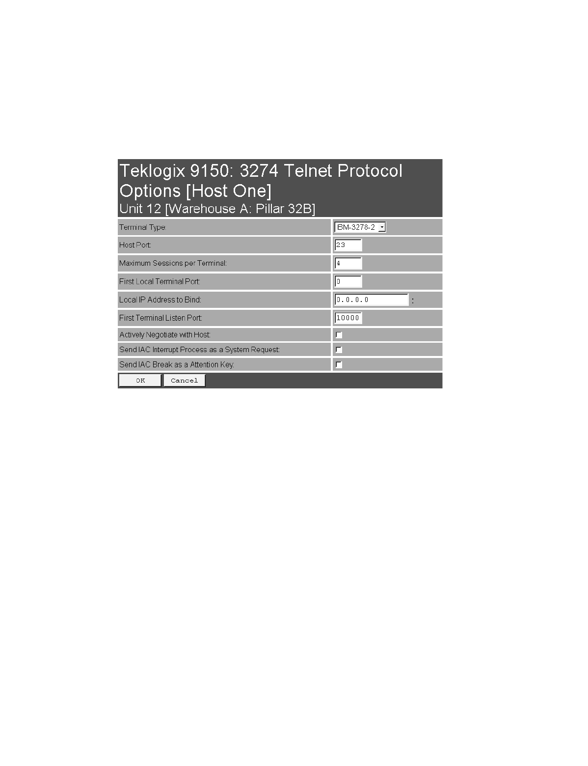
Chapter 5: Mini-Controller Configuration
3274/Telnet
Protocol Options
96 Teklogix 9150 Wireless Gateway User Manual
Terminal Type
This parameter allows you to choose the type of terminal to be emulated by the 9150
for this host. At present there is only one choice of terminal for 3274/Telnet:
the IBM 3278-2.
Host Port
This parameter allows you to enter a host port value for the selected 3274/Telnet host
connection. The default value is 23.
Maximum Sessions per Terminal
This parameter contains the maximum number of telnet sessions which are allowed
to originate from each terminal. The range is 0 to 127, with a default value of 4.

Teklogix 9150 Wireless Gateway User Manual 97
Chapter 5: Mini-Controller Configuration
3274/Telnet
Protocol Options
First Local Terminal Port
This parameter contains the port number from which the first terminal will connect
on outbound telnet sessions. The default value is 0.
Local IP Address to Bind
This parameter contains the IP address of the network adaptor in the 9150 from
which the first terminal will connect on outbound telnet sessions.
First Terminal Listen Port
This parameter specifies the first port number at which the 9150 will listen for telnet
connection requests to the terminals. The default value is 10000.
Actively Negotiate with Host
If this parameter is enabled, the 9150 negotiates with the host during setup of the
telnet connection.
Send IAC Interrupt Process as a System Request
If this parameter is enabled, the 9150 sends the IAC Interrupt Process request to the
host as a 3274 System Request.
Send IAC Break as an Attention Key
If this parameter is enabled, the 9150 sends the IAC Break request to the host as a
3274 Attention key.
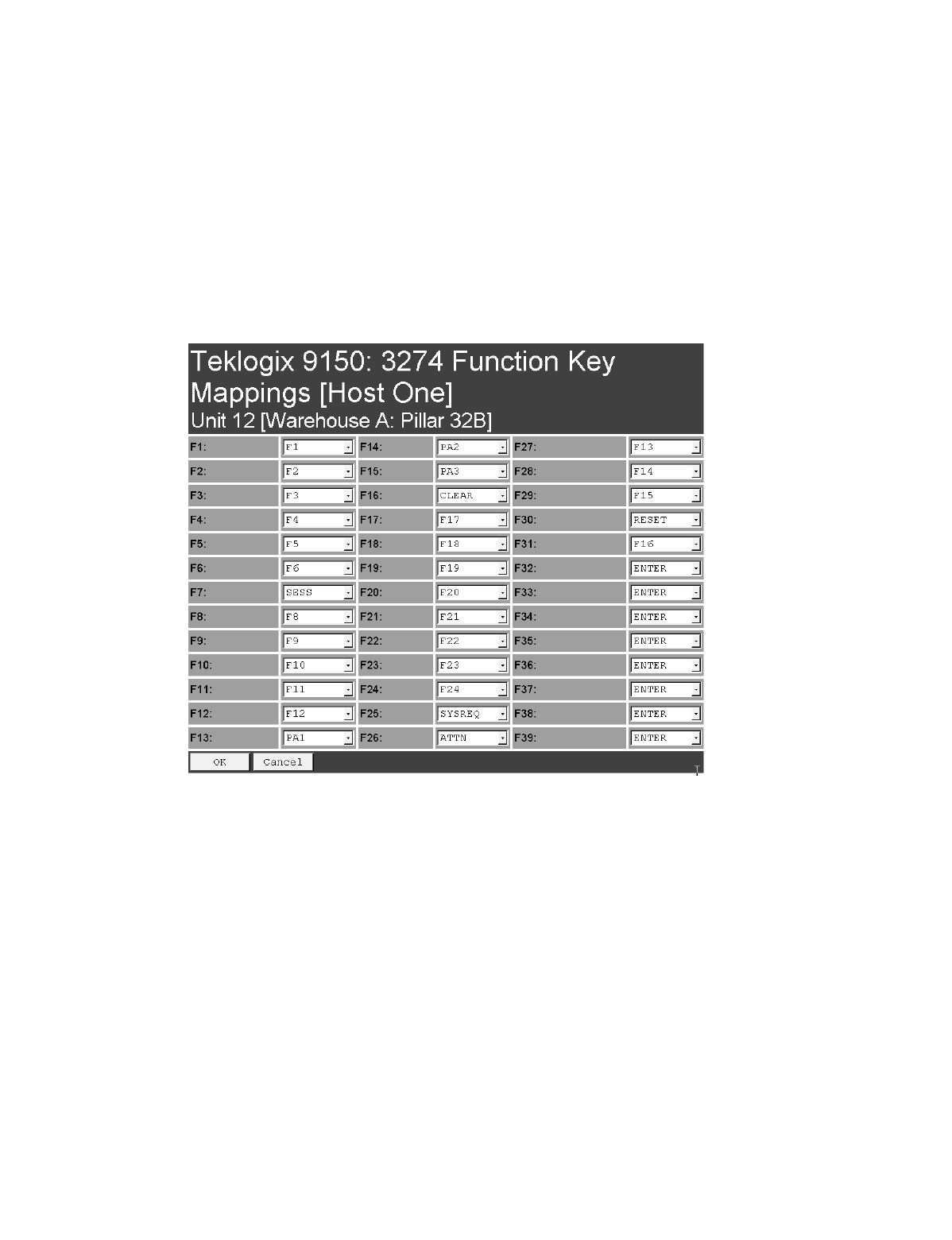
Chapter 5: Mini-Controller Configuration
3274/Telnet
Function Key Mappings
98 Teklogix 9150 Wireless Gateway User Manual
5.3.3.3 Function Key Mappings
This page differs depending on the type of emulation selected in the General Host
Options page. The 9150 displays this version of the Function Key Mapping page
when you select 3274 emulation for this host.
Function key n
The Function Key parameter allows you to select a code that will be sent to the host
when you press a function key on the terminal. Each function key may be chosen
from the same range of possible codes; however, each function key has a different
default code. The default values are shown on this page.
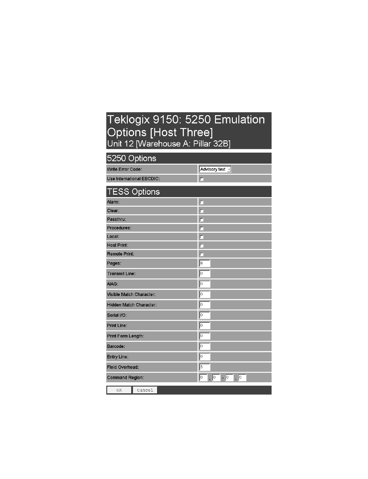
Teklogix 9150 Wireless Gateway User Manual 99
Chapter 5: Mini-Controller Configuration
5250/Telnet
Emulation Options
5.3.4 5250/Telnet
5.3.4.1 Emulation Options

Chapter 5: Mini-Controller Configuration
5250/Telnet
Emulation Options
100 Teklogix 9150 Wireless Gateway User Manual
The 9150 displays this version of the Emulation Options page after you have
selected the 5250/Telnet emulation/protocol combination for this host connection.
With IBM 5250, or IBM 3274 emulation, the 9150 mini-controller converts the
application data stream from the host to TESS (Teklogix Screen Subsystem)
commands. Some of the parameters in this page govern the conversion of the host
screens to TESS.
Write Error Code
If advisory text is selected here, the 9150 sends error codes to the terminal screen as
advisory text, which is written at the bottom of the screen. If screen text is chosen,
the 9150 sends the error codes as regular screen text.
Use International EBCDIC
If this parameter is enabled, the 9150 will swap the positions of the ! and ] charac-
ters in the EBCDIC character table.
Alarm
If this parameter is enabled, terminals will beep when the word “ALARM”
(in capital letters) appears on the application screen, in the location specified by the
Command Region parameter (see page 109). The word “ALARM” should be a
display-only field.
Note: The Command Region parameter must be enabled for this
parameter to work.
Clear
If this parameter is enabled, the 9150 mini-controller creates an empty entry field
for an entry field that is filled with spaces.
Some host applications rely on the video attributes of displayed characters to high-
light fields, particularly entry fields. For example, the application screen may define
all entry fields with reverse video and fill the field with spaces. This is effective on
terminals that support reverse video, but on terminals that do not, it can make the
field invisible since it is made up entirely of spaces.

Teklogix 9150 Wireless Gateway User Manual 101
Chapter 5: Mini-Controller Configuration
5250/Telnet
Emulation Options
By default, all empty entry fields displayed at the Teklogix terminal are highlighted
by the “entry character” chosen in the terminal’s configuration (not all Teklogix ter-
minals support video attributes). The Clear feature creates an empty entry field in
place of an entry field filled with spaces.
Note: This operation is only performed on screens received from the host. Data
sent to the host remains unaffected.
Passthru
If this parameter is enabled, the 9150 allows the host to send data directly to the RF
terminal’s serial port. This is most commonly used for printing.
Preparing Host Screens for Pass-Through
On the screen to be sent through the terminal serial port, the word “PASSTHRU”
(in capital letters) must appear on the first line, starting on the second column. The
actual data to be sent to the terminal may start anywhere below the first line.
With 5250 or 3274 emulations, attributes occupy a position in the screen buffer. An
attribute placed between column 2 and the end of the word “PASSTHRU” will push
all following characters one position to the right. Therefore, any required attributes
should occupy column 1 of the first line (just preceding the word “PASSTHRU”).
Example:
where @ is an attribute.
When the 9150 is finished sending the data to the terminal’s printer, it will send an
“ENTER” key to the host. The host must wait for the “ENTER” key before sending
any more screens (including other “PASSTHRU” screens) to this terminal.
Note: Refer to the 7030/8055/8060 Terminals User Manual for information
about setting parameters on the terminal for pass-through.
column: 1 2 3 4 5 6 7 8 9
line 1: @ P A S S T H R U @
line 2: @ P A R T : 1 2 3 4 5

Chapter 5: Mini-Controller Configuration
5250/Telnet
Emulation Options
102 Teklogix 9150 Wireless Gateway User Manual
Procedures
If this parameter is enabled, the host may send TESS procedures through the 9150
to the terminals. A TESS procedure is a group of TESS commands that can be exe-
cuted by the TESS execute procedure command.
Local
If this parameter is enabled, the 9150 allows the host to provide pages to be loaded
as local TESS procedures in the terminals.
The local procedures are selected from a menu at the terminal. The terminals can
perform these procedures when they are offline. Later when the terminals are online,
they send the results of these functions to the host.
Note: The Procedures parameter must also be enabled for Local to work.
Host Print
When this parameter is enabled, the host can send extra data to the terminal’s
screens, and instruct the terminal to print it. This is in contrast to the Local Print fea-
ture, where the terminal makes the initial print request.
The text that is passed to the printer is formatted into the 24 x 80 application screen.
If the host can initiate the print operation, the text is printed. The 9150 identifies the
additional text as a print page by the presence of the word “PRINT” (in capital let-
ters) beginning in the 2nd column of line 13 on the 24 x 80 screen. The word
“PRINT” should be defined as display-only text.
The print page is positioned below the terminal’s display page (see Figure 5.6 on
page 103). The size of the print page is always the same as the terminal’s display
page (assuming that in the terminal’s configuration, the page length is less than 12
lines).
When Host Print is enabled, the 9150 passes the print page to the terminal after
receiving the application screen from the host.

Teklogix 9150 Wireless Gateway User Manual 103
Chapter 5: Mini-Controller Configuration
5250/Telnet
Emulation Options
Figure 5.6 Application Screen With Print Page
Notes:
1. Unlike the Passthru option, when using Host Print no escape com-
mands can be sent to the printer.
2. Support for printing must be enabled at the terminal in its
Printer command under the TESS Features menu; refer to the
7030/8055/8060 Terminals User Manual for more information.
Remote Print
When this parameter is enabled, the 9150 sends the print page to a terminal when-
ever the terminal requests it (by sending the “F17” function key from the terminal,
or the “PRINT” key on older terminals). The 9150 sends the function response back
to the host.
This is in contrast to Host Print, where the host makes the initial print request.
Note: Support for printing must be enabled at the terminal level. Refer to the
7030/8055/8060 Terminals User Manual for more information.
1
2
3
4
5
6
7
8
9
10
11
12
13
14
15
16
17
18
19
20
21
22
23
24
Display Page (8 x 40)
Print Page (8 x 40)
PRINT

Chapter 5: Mini-Controller Configuration
5250/Telnet
Emulation Options
104 Teklogix 9150 Wireless Gateway User Manual
Pages
This parameter determines the number of host screens (or pages) stored at
the terminal, to a maximum of 16.
The 9150 reduces data transmitted to the terminals by using the terminal’s capability
to store a page of data for each screen it displays. The 9150 maintains an image of
each page stored at the terminal. After receiving an application screen, the 9150 tries
to match the screen with a stored page.
If a similar page is already in the terminal’s memory, the 9150 instructs the terminal
to re-display its copy of the page; only the necessary changes are sent from the con-
troller. If no match is found, the complete page is sent to the terminal over the
radio link.
Note: There is a corresponding parameter on the terminal itself, and the actual
number of saved pages will be the smaller of the two values.
Transmit Line
When this feature is enabled, all modified data at the terminal will be automatically
transmitted when the operator enters data into a transmit-upon-entry field.
The value in this textbox specifies the line on the screen which is designated the
transmit line. The last entry field above or on the transmit line on the screen will be
identified as the transmit-upon-entry field. If any entry fields exist on lines below
the transmit line, no entry field will be designated as the transmit-upon-entry field.
A value of 0 (zero) disables this feature. A value of 24 will cause the last entry field
on each application screen to be defined as transmit-upon-entry.
AIAG
This parameter provides auto-locate and fill for input coming from bar code readers.
When bar code data is entered at a terminal, the terminal searches for “AIAG” fields
on the current page that can accept the bar code data. The data preloaded into the
“AIAG” field by the application program determines whether or not the bar code
data is accepted.
At the 9150 mini-controller, a decimal value of an ASCII character from 0 to 127
is set to match the “AIAG Field Identifier” set at the host. A value of 0 disables
this feature.

Teklogix 9150 Wireless Gateway User Manual 105
Chapter 5: Mini-Controller Configuration
5250/Telnet
Emulation Options
The format of the preloaded data is as follows:
<mode> <AIAG prefix(data)>
The mode character used with the command allows for different operating modes to
suit various application operations. The automatic locate and fill operation applies
only to data received from a bar code reader. Descriptions of the modes and AIAG
prefix are listed in the table below. These modes are set at the host.
Table 5.3 Mode Functions And AIAG Prefix Description
Mode Function
0Display prefix, send prefix to host.
1Do not display prefix, send prefix to host.
2Display prefix, do not send prefix to host.
3Do not display prefix, do not send prefix to host.
+4
Add 4 to above values to cause transmit to host when all AIAG fields with 4
set are filled. Function 0 is “pressed” if there are any fields
with this bit set, and all fields with this bit set have been filled by
operator input.
+8 Add 8 to above values to allow overwrite of previously entered data.
+16 Add 16 to above values to indicate cursor position priority for search and fill.
AIAG Prefix
(data) The text to be matched in the AIAG field.
Chapter 5: Mini-Controller Configuration
5250/Telnet
Emulation Options
106 Teklogix 9150 Wireless Gateway User Manual
Example:
The information in the sample screen below is defined at and sent from the host. It
includes the “AIAG Identifier” – the tag identifying this as an AIAG field – followed
by the mode, in this case Mode 0, and finally, the “AIAG Prefix” – I.
Figure 5.7 AIAG Field Sent From The Host
When the information arrives at the terminal screen, the appropriate AIAG field for
the scanned information is located using the “AIAG Identifier”. Because Mode 0
was set at the host, the “AIAG Prefix” – I – is displayed on the terminal screen, and
when this screen is completed, the prefix will be sent back to the host.
Figure 5.8 AIAG Field Sent To The Terminal
Visible Match Character
By inserting a special ASCII character directly before an entry field, the application
program distinguishes a “match field” from an entry field. For example, suppose an
angle bracket “>” is defined for visible match fields. Inserting “>” immediately
preceding the entry field identifies it as a match field, as illustrated below.
Part #> ___________
Item No. @0
AIAG Information From Host
AIAG Prefix (data)
Mode
AIAG Field Identifier
I
Item No. I
AIAG Information From Host To Terminal Screen
@
AIAG Prefix (data)
AIAG Field Identifier

Teklogix 9150 Wireless Gateway User Manual 107
Chapter 5: Mini-Controller Configuration
5250/Telnet
Emulation Options
The range for this parameter – 0 to 127 – represents the decimal values of
ASCII characters. A value of 0 disables this feature. The ASCII decimal value
entered at the 9150 must coincide with the value set by the application program.
To use the Visible Match feature, the host computer preloads data into a match
entry field; the data is visible on the terminal screen. The preloaded data sent to a
terminal can consist of exact characters, special match characters or a combination
of the two. Refer to the table below for match characters recognized by
Teklogix terminals.
If an entry does not match the preloaded data, the entry is displayed, the terminal
beeps, and the cursor moves to the first position in the match field. The operator can
either make another entry in the match field, or move the cursor to a new field.
When an entry (even one that doesn’t match the preloaded data) is made in a match
field, the entry is sent to the host as part of the terminal’s modified data during the
next transmission.
Table 5.4 Match Characters
Character Description
#Match a number.
&Match a letter (either case).
^Match an uppercase letter.
_Match a lowercase letter.
|Match an alphanumeric character.
"Match a letter, number or space.
?Match a punctuation character.
'Match any character.
:Match all character positions in the field with the preceding character.
;Match any remaining characters, but not necessarily the remainder of the field,
with the preceding character.

Chapter 5: Mini-Controller Configuration
5250/Telnet
Emulation Options
108 Teklogix 9150 Wireless Gateway User Manual
Example:
Suppose you want to preload an entry field with a part number. If the part number is
known, you can preload the field with that part number. If more flexibility is needed,
and the part number always begins with two alphabetic characters followed by a
hyphen and four digits, the match string for the field would be: &&–#### .
Hidden Match Character
Unlike data in a “visible match” field, the preloaded data in a “hidden match” field
is not displayed at the terminal.
Note: Refer to “Visible Match Character” on page 106 for detailed information
about field matching.
The range for this parameter – 0 to 127 – represents the decimal values of ASCII
characters. A value of 0 disables this feature. The ASCII decimal value entered at
the 9150 must coincide with the value set by the application program.
Serial I/O
Serial I/O fields are special entry and fixed fields that accept input from and output
to a serial port. The application program distinguishes this field as Serial I/O by pre-
ceding the field with a special character.
If this character precedes a fixed field, the data will be sent to the terminal’s serial
port. If it precedes an entry field, the field accepts data from the terminal’s
serial port.
The range for this parameter – 0 to 127 – represents the decimal values of ASCII
characters. A value of 0 (zero) disables this feature.
Print Line
This parameter allows you to enter the starting line number of the print page in the
application screen. A value of 1 causes the display page to be printed; a value of 0
(zero) disables this feature.
Print Form Length
This parameter sets the printer’s form length in lines. The range is 0 to 24.

Teklogix 9150 Wireless Gateway User Manual 109
Chapter 5: Mini-Controller Configuration
5250/Telnet
Emulation Options
Barcode
Barcode-input-only fields are special entry fields that only accept input from a bar
code reader. The application program distinguishes an entry field as barcode-input-
only by preceding the field with a special character.
The range for this parameter – 0 to 127 – represents the decimal values of ASCII
characters. A value of 0 (zero) disables this feature.
Entry Line
This parameter contains the number of the first line displayed if there is no entry
field in the upper-left portion of the screen, and if an entry field is at or below
this line.
The Entry Line parameter allows an automatic offset within the host screen, so that
the area displayed by the terminal includes an entry field that would normally be out
of bounds. Normally, Teklogix terminals only display the upper-left corner of the
application screen because of their smaller display size.
Field Overhead
This parameter contains the maximum number of characters allowed between two
fixed fields which still allows the 9150 to join them into one field.
Sometimes the 9150 will join two adjacent fixed fields and then send them as one
field. This reduces the overhead on the radio link.
For example, if two fields were 4 characters apart and this parameter was ‘5’, then
these fields would be joined into one.
Command Region
This parameter defines a region of the host screen which the 9150 will examine for
the presence of reserved commands.
The four numbers in the Command Region textboxes represent the row and column
addresses of the upper left corner and the lower right corner of the command region.
The first textbox of each pair contains the row number; the second contains the
column number. The range of row values is 0 to 24; column values are 0 to 80.
To define the last two lines of the host screen as the command region, for example,
enter the values 23, 1 and 24, 80.
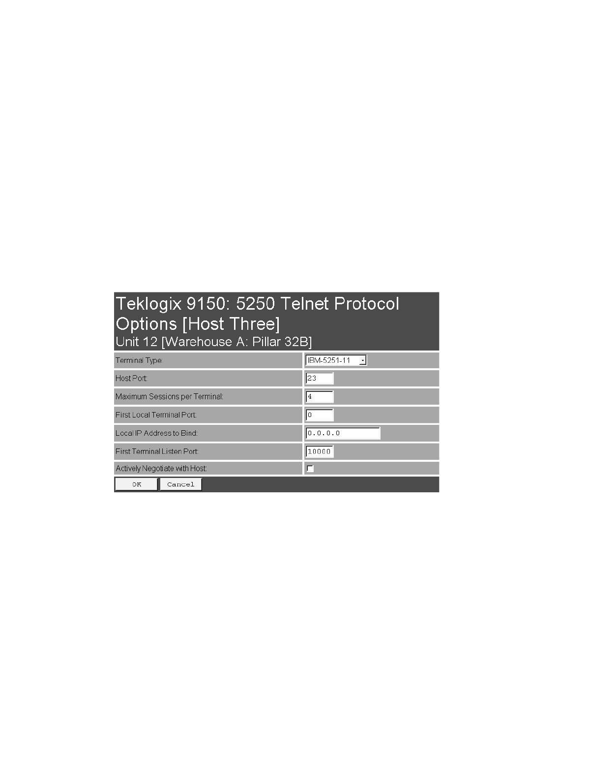
Chapter 5: Mini-Controller Configuration
5250/Telnet
Protocol Options
110 Teklogix 9150 Wireless Gateway User Manual
Currently, the only command supported is ALARM (refer to page 100 for details on
this command). When the word “ALARM” is placed anywhere within the command
region, the 9150 will send a TESS beep command to the terminal.
5.3.4.2 Protocol Options
This page differs depending on the type of emulation and protocol selected in the
General Host Options page. The 9150 displays this version of the Protocol Options
page when you select the emulation/protocol combination of 5250/Telnet for
this host.
Terminal Type
This parameter allows you to choose the type of terminal to be emulated by the 9150
for this host. At present there are two choices of terminal for 5250/Telnet:
the IBM 5251-11 and IBM 5555-B01.
Host Port
This parameter allows you to enter a host port value for the selected 5250/Telnet host
connection. The default value is 23.

Teklogix 9150 Wireless Gateway User Manual 111
Chapter 5: Mini-Controller Configuration
5250/Telnet
Protocol Options
Maximum Sessions per Terminal
This parameter contains the maximum number of telnet sessions which are allowed
to originate from each terminal. The range is 0 to 127, with a default value of 4.
First Local Terminal Port
This parameter contains the port number from which the first terminal will connect
on outbound telnet sessions. The default value is 0.
Local IP Address to Bind
This parameter contains the IP address of the network adaptor from which the first
terminal will connect on outbound telnet sessions.
First Terminal Listen Port
This parameter specifies the first port number at which the 9150 will listen for telnet
connection requests to the terminals. The default value is 0.
Actively Negotiate with Host
If this parameter is enabled, the 9150 negotiates with the host during setup of the
telnet connection.
Chapter 5: Mini-Controller Configuration
5250/Telnet
Function Key Mappings
112 Teklogix 9150 Wireless Gateway User Manual
5.3.4.3 Function Key Mappings
This page differs depending on the type of emulation selected in the General Host
Options page. The 9150 displays this version of the Function Key Mapping page
when you select 5250 emulation for this host.
Function key n
The Function Key parameter allows you to select a code that will be sent to the host
when you press a function key on the terminal. Each function key may be chosen
from the same range of possible codes; however, each function key has a different
default code. The default values are shown on this page.

Teklogix 9150 Wireless Gateway User Manual 113
Chapter 5: Mini-Controller Configuration
ANSI/Telnet
Emulation Options
5.3.5 ANSI/Telnet
5.3.5.1 Emulation Options
The 9150 displays this version of the Emulation Options page after you have
selected the ANSI/Telnet emulation/protocol combination for this host connection.
Host Timeout
The Host Timeout is the interval (in ticks, or 60ths of a second) between bursts of
data received from the host. The range is 0 to 255, with a default value of 15.
If the 9150 does not receive any characters from the host after this timeout has
elapsed, it assumes that the host has finished sending data and is waiting for user
input (in other words, it assumes that a screen of data has been completed).
Important: The Page parameter (page 115) must be enabled in order to change
the value in the Host Timeout parameter.

Chapter 5: Mini-Controller Configuration
ANSI/Telnet
Emulation Options
114 Teklogix 9150 Wireless Gateway User Manual
Escape Timeout
The Escape Timeout is the length of time (in ticks, or 60ths of a second) that the
9150 will hold an “ESC” received from the host, and consider the next received byte
to be part of an escape sequence. The range is 0 to 255, with a default value of 12.
When this timeout has elapsed, the host will have to send another “ESC” character
to start an escape sequence.
Note: This is especially important when an ESC is at the end of a data packet.
Threshold
The Threshold is the minimum number of bytes of update data for the terminal
screen which must be received from the host before the 9150 will store the screen as
a new “saved page”. The range is 0 to 999, with a default value of 200.
Important: The Page parameter (page 115) must be enabled in order to change
the value in the Threshold parameter.
Echo
If this parameter is enabled, the 9150 uses “Smart” Echo. This mode reduces the
amount of data sent to the terminal by decreasing the number of radio transmissions.
Ordinarily, when a character mode application is being used, each keystroke is sent
to the host in one transmission, and the character is echoed by the host in another
transmission. When “Smart” Echo is enabled, the 9150 will not send the host echo
to the terminals if it matches the data sent from the terminal. Thus, the number of
radio transmissions is reduced.
This mode also reduces or eliminates the delay between typing a character on the
keyboard and displaying the character echoed by the host. The maximum number of
characters waiting for echo is 25. Any additional characters will be sent to the host
but not displayed.
Notes:
1. This parameter also determines whether an ANSI parameter query is
sent to the terminal.
2. “Smart” Echo also needs to be enabled at the terminal (refer to the
7030/8055/8060 Terminals User Manual).

Teklogix 9150 Wireless Gateway User Manual 115
Chapter 5: Mini-Controller Configuration
ANSI/Telnet
Emulation Options
ANSI
If this parameter is enabled, the 9150 uses ANSI escape code filtering. When
escape-code filtering is enabled, ANSI escape codes not supported by the
terminals will be filtered out of the data stream to reduce radio traffic. The terminals
currently support most, if not all, standard ANSI escape sequences, so this parame-
ter should be disabled in most cases.
Function Key Remapping
If this parameter is enabled, the 9150 remaps the function keys for this host
connection as defined in the Function Key Remapping page (page 121).
Page
If this parameter is enabled, the 9150 uses page saving, reducing data
transmitted to the terminals.
The 9150 maintains an image of each page stored at the terminal. After receiving an
application screen, the 9150 tries to match the screen with a stored page. If the page
is already in the terminal, the 9150 instructs the terminal to redisplay its stored copy
of the page; no data need be sent across the radio link for that page. If the 9150 finds
no match for the page, the complete page is sent to the terminal.
Note: When page saving is enabled, the number of saved pages is that which is
set on the terminal. Refer to the 7030/8055/8060 Terminals User Manual
for details.
RLE
If this parameter is enabled, the 9150 uses run-length encoding (RLE) on the data it
sends across the radio link. RLE compresses repeated characters going from the host
to the terminal. If repeated characters are found in the data stream, the first one is
sent, followed by a short escape sequence (3 or 4 characters) which tells the terminal
how many times to repeat this character. In this way RLE compresses the data and
decreases the total amount of radio-link traffic.
Convert 7 to 8 Bits
If this parameter is enabled, the 9150 converts 7-bit control sequences to their 8-bit
equivalents in ANSI data streams going to the terminals. This replaces two-charac-
ter escape sequences with a single equivalent character, compressing the data.
Chapter 5: Mini-Controller Configuration
ANSI/Telnet
Protocol Options
116 Teklogix 9150 Wireless Gateway User Manual
5.3.5.2 Protocol Options
This page differs depending on the type of emulation and protocol selected in the
General Host Options page. The 9150 displays this version of the Protocol Options
page when you select the emulation/protocol combination of ANSI/Telnet for
this host.

Teklogix 9150 Wireless Gateway User Manual 117
Chapter 5: Mini-Controller Configuration
ANSI/Telnet
Protocol Options
Terminal Type
This parameter specifies the type of terminal to be emulated by the 9150, either a
VT100 or VT200.
Host Port
This parameter specifies the value for the host port for the selected ANSI host con-
nection. The default value is 23.
Maximum Sessions per Terminal
This parameter contains the maximum number of telnet sessions which are allowed
to originate from each terminal. The range is 0 to 127, with a default value of 4.
First Local Terminal Port
This parameter specifies the port number from which the 9150 attempts a telnet con-
nection for the first terminal. The default value is 0.
Additional telnet sessions are assigned higher port numbers.
Local IP Address to Bind
This parameter specifies the IP address of the 9150 interface that connects to this
host. It is used along with the local port numbers to create a unique socket for each
terminal session.
First Terminal Listen Port
This parameter specifies the lowest port number at which the 9150 listens for telnet
connections initiated by the host. The default value is 10000.
TCP Session Request Key
This parameter contains the decimal ASCII character code of the character which
will prompt the terminal to request a new ANSI terminal session. The range is 0 to
255, with a default value of 1.

Chapter 5: Mini-Controller Configuration
ANSI/Telnet
Protocol Options
118 Teklogix 9150 Wireless Gateway User Manual
Session Cycle Key
This parameter contains the decimal ASCII character code of the character which
will prompt the terminal to display the next ANSI terminal session. The range is 0 to
255, with a default value of 2.
Last Active Session Key
This parameter contains the decimal ASCII character code of the character which
will prompt the terminal to display the last ANSI terminal session. The range is 0 to
255, with a default value of 5.
Auto-telnet/login Enable
This parameter enables you to disable or enable automatic connection of telnet ses-
sions from terminals to this host. The choices provided are: Disable; Enable Auto-
telnet; Enable Auto-telnet/login. The default value is Disable.
When Auto-telnet is disabled, telnet sessions from the terminals to the host must be
initiated manually from the terminals.
When Auto-telnet is enabled, the 9150 initiates one telnet session from each termi-
nal whose terminal number is mapped to this host. Additional telnet sessions may be
initiated from each terminal to the host, but they must be initiated manually.
Note: Auto-telnet sessions are only initiated for terminals which are “online”
(turned on and operating properly on the Teklogix RF network).
When Auto-telnet and Auto-login are enabled, the 9150 initiates one telnet session
from each terminal whose terminal number is mapped to this host. It then logs each
session in to the host using the User ID and Password provided in this page.
Note: The User ID and Password is identical for all Auto-telnet sessions
automatically logged in to this host.

Teklogix 9150 Wireless Gateway User Manual 119
Chapter 5: Mini-Controller Configuration
ANSI/Telnet
Protocol Options
Auto-telnet Host
This parameter contains the host name or IP address for the host to which the 9150
connects Auto-telnet sessions.
Note: A host name placed in this textbox must be “resolvable” by the 9150:
the 9150 must be able to obtain an IP address for it. For example, the host
name may correspond to an entry in the 9150’s host table, or the 9150
may be able to query a domain-name server.
Any host name which can be used at the terminal’s TCP> prompt may be
used here.
Auto-telnet Terminal Prompt
This parameter contains the text presented to the user to request a login. The charac-
ters can be any ASCII string, with a maximum of 32 characters. The default is no
text, just press <ENTER> to login.
Auto-login User ID
This parameter contains the user ID presented by the 9150 to the host for the
Auto-login sessions. The characters can be any ASCII string acceptable to the host,
with a maximum of 15 characters.
Auto-login Password
This parameter contains the password presented by the 9150 to the host for the
Auto-login sessions. The characters can be any ASCII string acceptable to the host,
with a maximum of 15 characters.
Auto-login User ID prompt
The 9150 compares the text in this textbox to the text presented to it by the host.
When they match, the 9150 assumes that the host has just sent its request for a user
name, and it sends the user ID specified in the Auto-Login User ID parameter to the
host. The characters can be any ASCII string, with a maximum of 15 characters.
The default text is gin: .
Note: The match string should be as short as possible, yet long enough to
uniquely identify the user-ID prompt. Do not include multi-part words
separated by space characters, since some hosts send out characters
other than space characters to present a space on the screen.

Chapter 5: Mini-Controller Configuration
ANSI/Telnet
Protocol Options
120 Teklogix 9150 Wireless Gateway User Manual
Auto-login Password prompt
The 9150 compares the text in this textbox to the text presented to it by the host.
When they match, the 9150 assumes that the host has just sent its request for a pass-
word, and it sends the password specified in the Auto-Login Password parameter to
the host. The characters can be any ASCII string, with a maximum of 15 characters.
The default text is word: .
Note: The match string should be as short as possible, yet long enough to
uniquely identify the password prompt. Do not include multi-part words
separated by space characters, since some hosts send out characters
other than space characters to present a space on the screen.
Auto-login failed login
The 9150 compares the text in this textbox to the text presented to it by the host.
When they match, the 9150 assumes that the host has just sent a string informing the
terminal of a failed login attempt. The 9150 then presents the Auto-telnet Terminal
Prompt on the terminal’s screen to request the user to login manually. The characters
can be any ASCII string, with a maximum of 15 characters. The default text
is incorrect .
Note: The match string should be as short as possible, yet long enough to
uniquely identify the failed-login prompt. Do not include multi-part words
separated by space characters, since some hosts send out characters
other than space characters to present a space on the screen.

Teklogix 9150 Wireless Gateway User Manual 121
Chapter 5: Mini-Controller Configuration
ANSI/Telnet
Function Key Mappings
5.3.5.3 Function Key Mappings
This page differs depending on the type of emulation selected in the General Host
Options page. The 9150 displays this version of the Function Key Mapping page
after you have selected the ANSI/Telnet emulation/protocol combination for this
host connection.

Chapter 5: Mini-Controller Configuration
ANSI/Telnet
Function Key Mappings
122 Teklogix 9150 Wireless Gateway User Manual
Function key n
The Function Key parameter allows you to select a code that will be sent to the host
when you press a function key on the terminal. Each function key may be chosen
from the same range of possible codes; however, each function key has a different
default code. The default values are shown on the screen on page 121.

Teklogix 9150 Wireless Gateway User Manual 123
ACCESS POINT CONFIGURATION 6
6.1 Overview..............................125
6.2 Interfaces ..............................126
6.2.1 IEEE 802.11 (Frequency Hopping Radio Parameters) . . 126
6.2.2 IEEE 802.11 (Direct Sequence Radio Parameters) . . . . 128
6.3 MAC Bridge Parameters......................129
6.3.1 General Configuration . . . . . . . . . . . . . . . . . 131
6.3.2 Address Filters: MAC Address . . . . . . . . . . . . 132
6.3.3 Protocol Filters.....................133
6.3.3.1 Ethernet II Filters . . . . . . . . . . . . . . . . 136
6.3.3.2 LLC Filters ...................137
6.3.3.3 SNAP Filters...................138
6.3.3.4 Storm Detection.................139
6.4 Mobility Configuration ......................140
6.4.1 IAPP Parameters....................142

Teklogix 9150 Wireless Gateway User Manual 125
Chapter 6: Access Point Configuration
Overview
6.1 Overview
The 9150 can operate as an access point device between IEEE 802.11 wireless
and wired networks. Using IEEE 802.11 protocol, the 9150 provides a transparent
bridge between Teklogix or client terminals and a network controller or host. For an
overview of IEEE 802.11, please refer to “IEEE 802.11 Protocol” on page 10.
For operation as an access point, the parameters in the following pages must be
set appropriately.
Note: The 9150 main parameters should first be set up as described in Chapter
3: “9150 Main Configuration”.
Figure 6.1 9150 Access Point Configuration
ETHERNET
TCP/IP
9150
Wireless Gateway
RF Terminal
7040
Network Controller
RF Terminal
7035
9400
Hand-Held
Hand-Held
Chapter 6: Access Point Configuration
Interfaces
126 Teklogix 9150 Wireless Gateway User Manual
6.2 Interfaces
The pull-down menu shown for the Interfaces option indicates which interfaces have
been detected in use by the 9150, including one of two 802.11 PCMCIA radios:
•IEEE 802.11 FH: Proxim RangeLAN802 IEEE 802.11 FHSS 2.4 GHz.
•IEEE 802.11 DS: Lucent WaveLAN IEEE 802.11 DSSS 2.4 GHz.
Selecting a radio type from the drop-down list and entering “Configure” will open
the radio parameters page for that radio.
6.2.1 IEEE 802.11 (Frequency Hopping Radio Parameters)
When the Proxim RangeLAN802 IEEE 802.11 FHSS 2.4 GHz PCMCIA card is
installed in the 9150, the following radio parameters page is opened:

Teklogix 9150 Wireless Gateway User Manual 127
Chapter 6: Access Point Configuration
IEEE 802.11 (Frequency Hopping Radio Parameters)
Physical Address
This parameter shows the hardware address (MAC address) of the radio card.
A globally unique MAC address is assigned to each card by the card manufacturer.
The value cannot be changed.
Regulatory Domain
The regulatory domain value identifies the regulatory body’s country code for the
RF regulations with which the radio complies. For the USA, the regulatory body is
the FCC, for Canada it's Industry Canada, and for Europe it's ETSI. The hex value in
brackets beside the name is the code (as specified in the IEEE 802.11 standard) for
that domain. The country codes that are decoded into a name are listed below. For
other country codes the name portion will be replaced with "Unknown".
ESSID
This is the Extended Service Set Identifier parameter. The ESSID is an
alphanumeric character string of up to 32 characters and is case-sensitive. If your
network includes devices that use the DOS ODI Driver, select alphabetical charac-
ters in uppercase only to allow the DOS ODI devices to connect to the network as
well. The ESSID should be the same for all devices in a system.
Hopping Pattern
The combined settings for the Hopping Pattern and Hopping Set parameters deter-
mine the operating channel for a radio using frequency hopping. Please refer to your
network administrator for details.
Hopping Set
The combined settings for the Hopping Set and Hopping Pattern parameters deter-
mine the operating channel for a radio using frequency hopping. Please refer to your
system administrator for details.
Regulatory Body Domain Code Country
FCC-USA 0x10 USA (for DS radios this is also the code used
for Canada)
Industry Canada 0x20 Canada (currently only for FH radios, this may
change in the future)
ETSI-Europe 0x30 Most of Europe
Spain 0x31 Spain
France 0x32 France
MKK-Japan 0x40 Japan
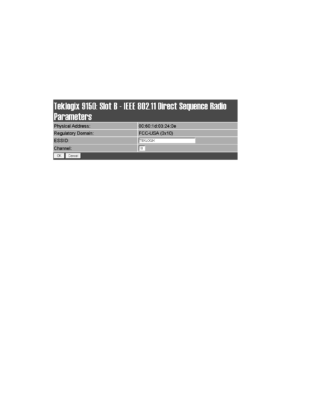
Chapter 6: Access Point Configuration
IEEE 802.11 (Direct Sequence Radio Parameters)
128 Teklogix 9150 Wireless Gateway User Manual
6.2.2 IEEE 802.11 (Direct Sequence Radio Parameters)
When the Lucent WaveLAN IEEE 802.11 DSSS 2.4 GHz PCMCIA card is installed
in the 9150, the following radio parameters page is opened:
Physical Address
This parameter shows the hardware address (MAC address) of the radio card.
A globally unique MAC address is assigned to each card by the card manufacturer.
The value cannot be changed.
Regulatory Domain
The regulatory domain value identifies the regulatory body’s country code for the
RF regulations with which the radio complies. For the USA, the regulatory body is
the FCC, for Canada it's Industry Canada, and for Europe it's ETSI. The hex value in
brackets beside the name is the code (as specified in the IEEE 802.11 standard) for
that domain. The country codes that are decoded into a name are listed on page 127.
For other country codes the name portion will be replaced with "Unknown".
ESSID
This is the Extended Service Set Identifier parameter. The ESSID is an
alphanumeric character string of up to 32 characters and is case-sensitive. If your
network includes devices that use the DOS ODI Driver, select alphabetical charac-
ters in uppercase only to allow the DOS ODI devices to connect to the network as
well. The ESSID should be the same for all devices in a system.
Channel
This parameter sets the operating channel for this radio, as determined by the system
administrator. For a listing of the allowable channels for each country, please see
“PC Card Radios” on page 145.
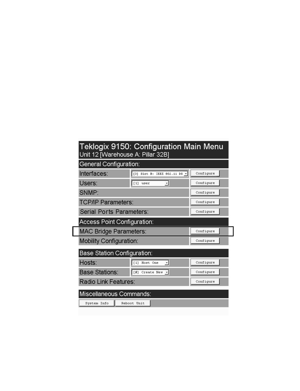
Teklogix 9150 Wireless Gateway User Manual 129
Chapter 6: Access Point Configuration
MAC Bridge Parameters
6.3 MAC Bridge Parameters
The MAC Bridge parameters consist of protocol filters which direct the 9150 to
forward or discard frames that contain a known protocol type. This enables the 9150
to be selective of what type of frames will be bridged over the radio, in order to limit
the amount of data on busy networks. Filtering frames is based on the protocol infor-
mation in the frame. This is discussed in detail in “Protocol Filters” on page 133.
The MAC Bridge Parameters page is entered from the Access Point Configuration
menu on the first page.

Chapter 6: Access Point Configuration
MAC Bridge Parameters
130 Teklogix 9150 Wireless Gateway User Manual
Figure 6.2 below charts the pages for the MAC bridge filters. Entering “OK” or
“Cancel” in the individual Filter pages will return you to the Bridge Parameters
page.
Figure 6.2 Overview Of MAC Bridge Configuration Menus
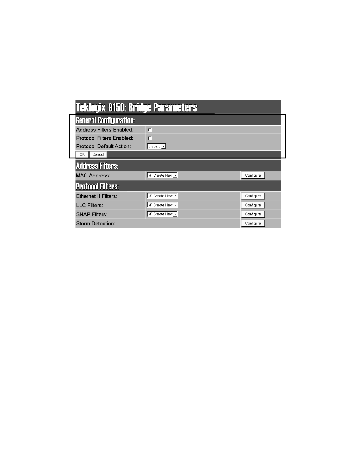
Teklogix 9150 Wireless Gateway User Manual 131
Chapter 6: Access Point Configuration
General Configuration
6.3.1 General Configuration
Address Filters Enabled
The checkbox in this parameter enables or disables the Address Filters function. If
filtering is enabled ( √ ), the 9150 can filter out frames based on destination MAC
addresses. The list of MAC addresses for filtering is set by the Address Filters option
on page 132. Frames are filtered and either forwarded or discarded, depending on
the rest of the settings in this configuration. If filtering is disabled, no filtering will
be done based on MAC addresses.
Protocol Filters Enabled
The checkbox in this parameter enables or disables the Protocol Filters function. If
filtering is enabled ( √ ), frames are filtered and either forwarded or discarded,
depending on the rest of the settings in this configuration. If filtering is disabled, no
filtering will be done based on protocol frames.
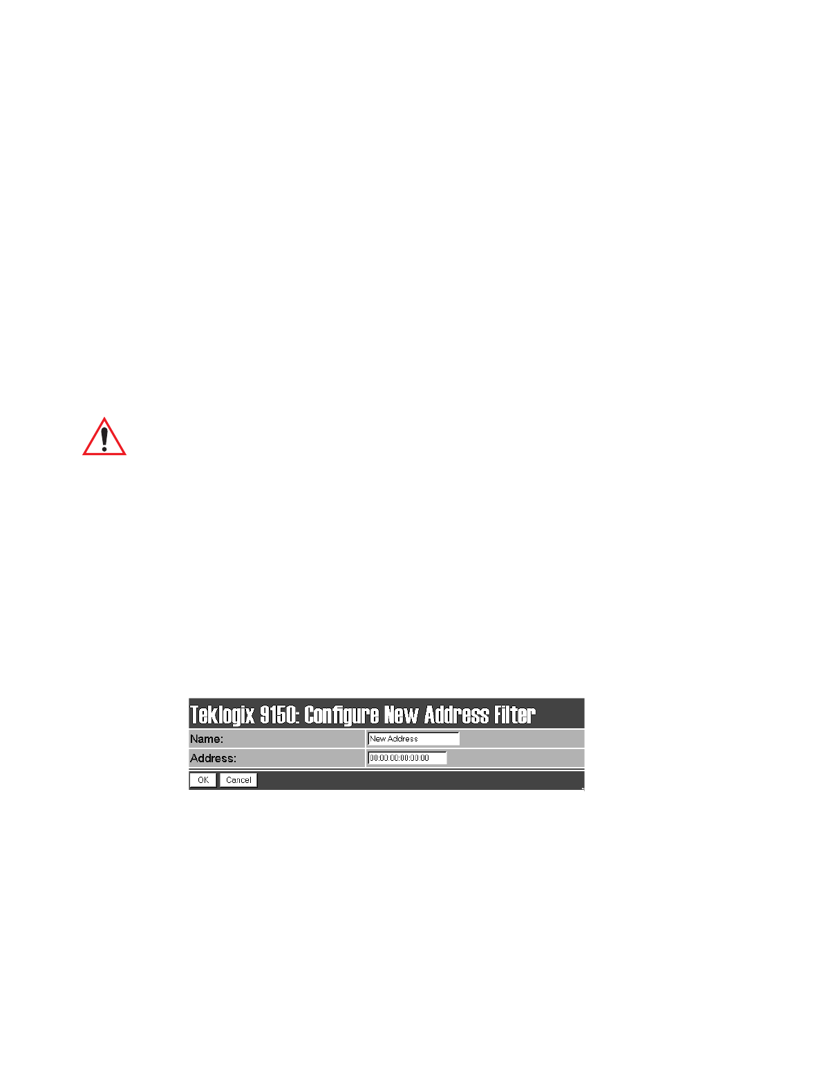
Chapter 6: Access Point Configuration
Address Filters: MAC Address
132 Teklogix 9150 Wireless Gateway User Manual
Protocol Default Action
This parameter determines which Protocol Default Action (discard or forward) will
be performed when the Protocol Filters are enabled. Each Protocol Filter (see
page 133) also has a forward/discard action associated with it. If a frame does not
match any of the filters set in the Protocol Filters configuration, then it will take the
Protocol Default Action selected in this parameter.
For example, the Protocol Default Action may be to discard all frames. If a type
field is matched in the configuration database, and the Filters action is forward, the
frame will be passed on. If the field is not matched, then the frame will be dis-
carded. Therefore if you want only IP frames forwarded, after selecting the appro-
priate IP Type in the Ethernet II Filters (see page 136) the discard setting here will
drop all frames containing other protocol types.
Important: If Protocol Filters Enabled is checked, and the Protocol Default
Action is discard, an HTTP browser will not be able to access the
9150’s configuration pages unless an ARP filter is defined to forward
ARP packets. To do this, configure Ethernet II Filters to forward pro-
tocol type 0x0806 (ARP) packets (see page 136). Alternatively, you
can create a static entry in the ARP table on the computer that is
running the browser.
6.3.2 Address Filters: MAC Address
The 9150 can use a list of destination MAC addresses to filter out frames. The MAC
addresses are those of any terminals associating with the 9150. If Address Filters on
page 131 is enabled, then any frame destined for any address in the list will be for-
warded. If an address is not on the list when Address Filters is enabled, the frame
will be discarded. Addresses are added to the filter list by entering the “Configure”
dialogue box from the Bridge Parameters menu.
Name
This is any name you wish to use to describe this terminal.
Address
This parameter provides the corresponding MAC address for the terminal.
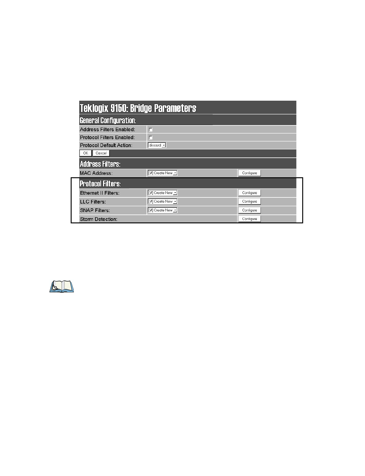
Teklogix 9150 Wireless Gateway User Manual 133
Chapter 6: Access Point Configuration
Protocol Filters
6.3.3 Protocol Filters
When the 9150 receives frames, it can forward or discard the messages by filtering
the protocol Type fields encapsulated in the frame. The filtering is done on three
types of Ethernet headers: Ethernet II, LLC and SNAP.
Figure 6.3 on page 134 illustrates the Ethernet header formats. The parameters to
configure these filters are described in the sections which follow.
Notes:
1. Although both LLC and SNAP headers are filtered on Ethernet
and Token Ring networks, Ethernet headers are not filtered on
Token Ring.
2. Throughout these menus, the values for all the protocol types are, by
convention, entered in hexadecimal, preceded by “0x”.
The fields for a basic IEEE 802.3 Ethernet frame consist of a six-byte destination
MAC address, followed by a six-byte source MAC address, and a two-byte protocol
Type. The final fields in a frame are the Data field and the FCS field (Frame Check
Sequence, or CRC). If the Type field contains a value that is greater than or equal to
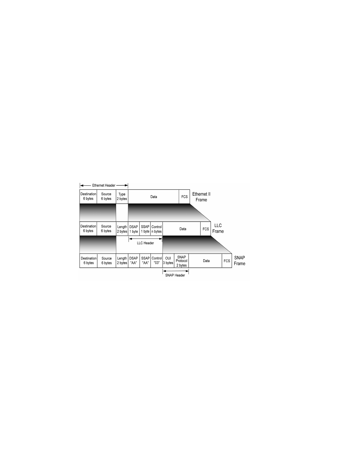
Chapter 6: Access Point Configuration
Protocol Filters
134 Teklogix 9150 Wireless Gateway User Manual
“0x0600”, it is assumed to be the protocol identifier for an Ethernet II header. This
field is used to determine which protocol is being used in the frame, and this is what
can be filtered (see “Ethernet II Filters” on page 136).
If the protocol Type is less than “0x05DC”, then the value is interpreted as a Length
field instead. It is assumed that an IEEE 802.2 Logical Link Control (LLC) header is
to follow the Length. This header consists of the Destination Service/Source Service
Access Point (DSAP/SSAP) and Control fields (see “LLC Filters” on page 137).
If the DSAP and SSAP are both “0xAA”, and the Control field has a value of
“0x03”, the LLC header will be followed by an extension which is a SNAP header.
The SNAP header includes the Organizational Unit Identifier (OUI) and the
protocol type (see “SNAP Filters” on page 138).
Figure 6.3 Ethernet Frame Types
The listboxes in the Protocol Filters option show the protocol filters already set in
the configuration database. Selecting a protocol name and then opening the “Config-
ure” dialog box gives a list of parameter settings that can be modified or deleted for
that protocol.
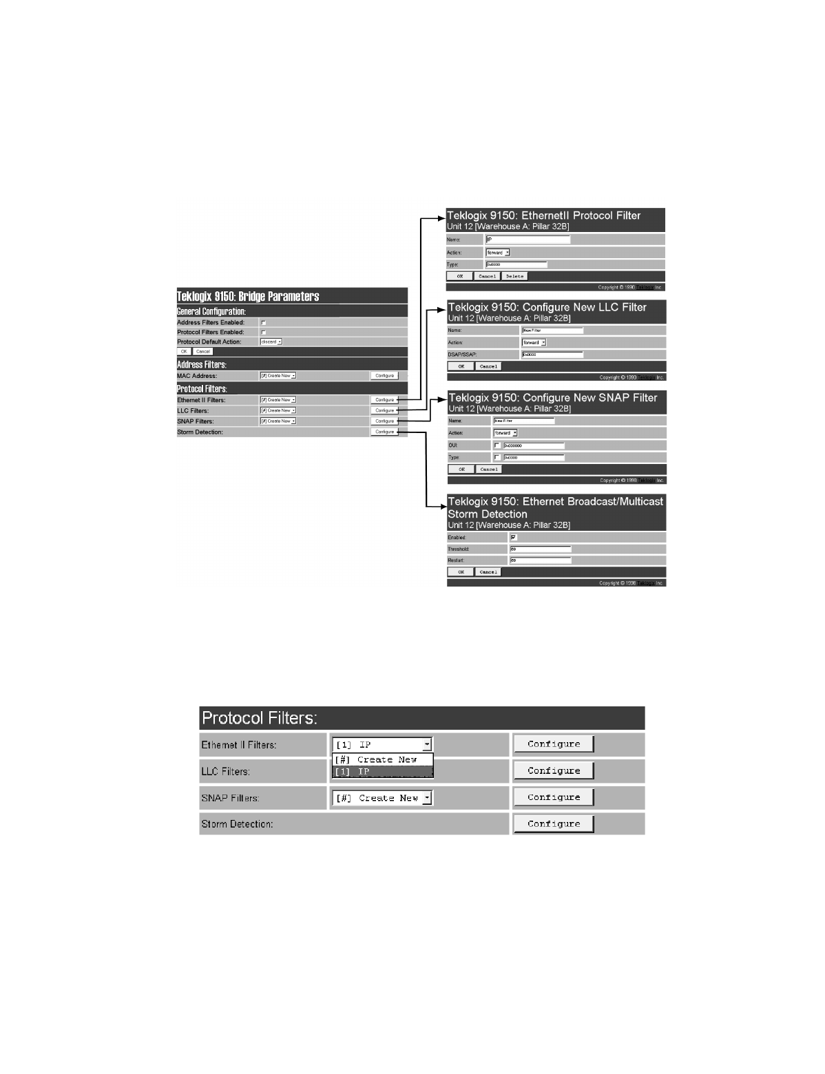
Teklogix 9150 Wireless Gateway User Manual 135
Chapter 6: Access Point Configuration
Protocol Filters
Figure 6.4 Protocol Filters Main Menu And Sub-menus
New filters can be added by selecting “[#] Create New” in the listbox before enter-
ing the “Configure” dialog box.
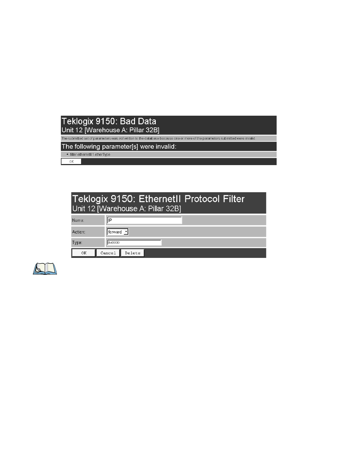
Chapter 6: Access Point Configuration
Protocol Filters
136 Teklogix 9150 Wireless Gateway User Manual
If a hexadecimal number is entered that is outside the minimum or maximum allow-
able value for these parameters, you will receive an alert that the Type value is
invalid for the specified protocol.
6.3.3.1 Ethernet II Filters
Note: This parameter is only valid for Ethernet networks. Ethernet II headers
are not filtered on Token Ring networks.
Name
This is any name you wish to use to describe this Ethernet II filter.
Action
This parameter can be set to either forward or discard frames with protocol types
that match this filter.
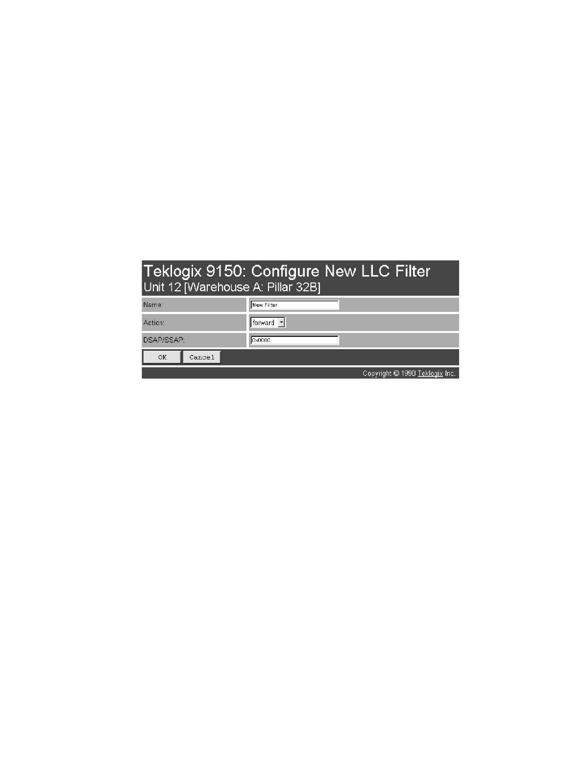
Teklogix 9150 Wireless Gateway User Manual 137
Chapter 6: Access Point Configuration
Protocol Filters
Type
The value entered in this parameter must be a four-digit hexadecimal number
ranging from 0x0600 to 0xFFFF, which represents the Ethernet II protocol type you
wish to filter. For example, if you only use TCP/IP, create two protocol filters, one to
forward IP (Type 0x0800) and the other to forward ARP (Type 0x0806). For a
listing of Ethernet II types, see “Ethernet II Types (RFC 1700)” on page B-1.
6.3.3.2 LLC Filters
Name
This is any name you wish to use to describe this LLC filter.
Action
This parameter can be set to either forward or discard frames with protocol types
that match this filter.
DSAP/SSAP
The value entered in the Destination Service/Source Service Access Point
(DSAP/SSAP) parameter must be a four-digit hexadecimal number ranging from 0
to 0xFFFF, where the first pair of digits is the DSAP and the last pair is the SSAP.
For a listing of DSAP/SSAP types, see “DSAP/SSAP Types” on page B-14.
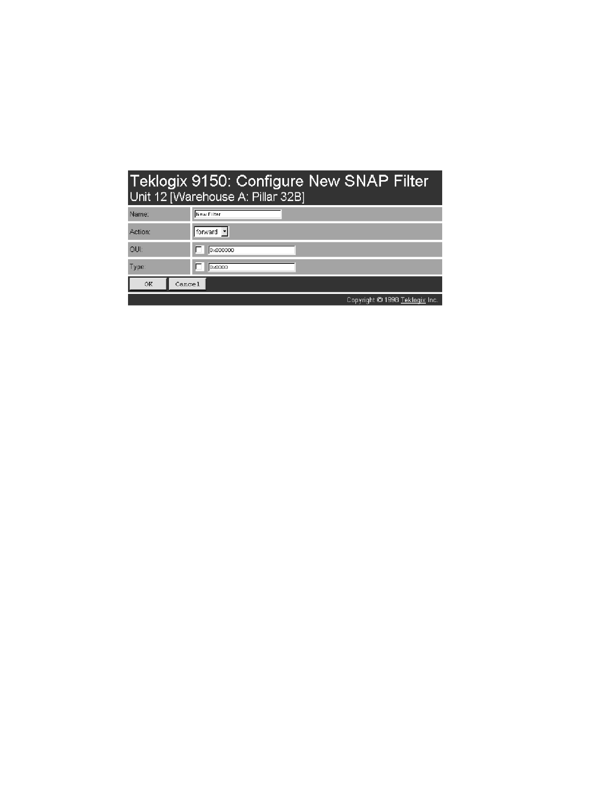
Chapter 6: Access Point Configuration
Protocol Filters
138 Teklogix 9150 Wireless Gateway User Manual
6.3.3.3 SNAP Filters
Name
This is any name you wish to use to describe this SNAP (SubNet Access Protocol)
filter.
Action
This parameter can be set to either forward or discard frames with protocol types
that match this filter.
OUI
The value entered in this parameter must be a six-digit hexadecimal number ranging
from 0 to 0xFFFFFF, which is the Organization Unique Identifier. When this
parameter is enabled ( √ ), the OUI will be filtered.
Type
The value entered in this parameter must be a four-digit hexadecimal number
ranging from 0 to 0xFFFF, which represents the SNAP type you wish to filter.
When this parameter is enabled ( √ ), this Type will be filtered.
For a short listing of OUI values, see “OUI Values” on page B-15.
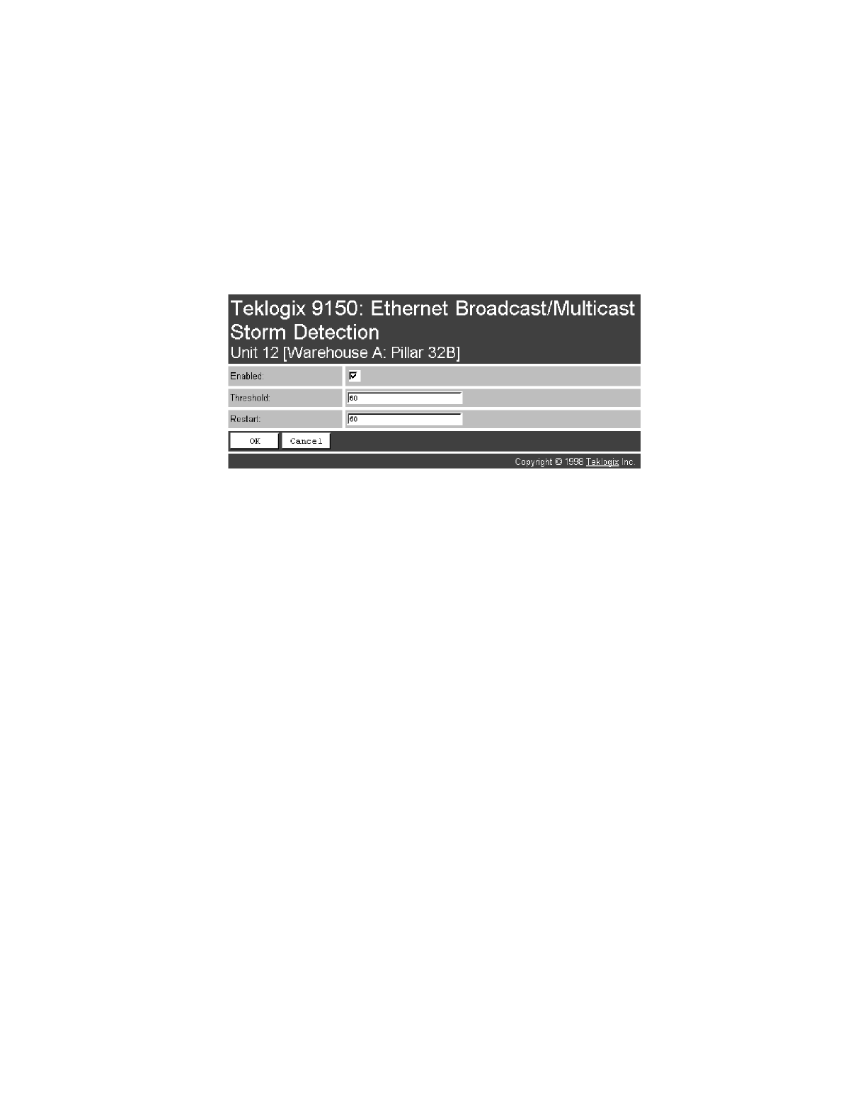
Teklogix 9150 Wireless Gateway User Manual 139
Chapter 6: Access Point Configuration
Protocol Filters
6.3.3.4 Storm Detection
This filter parameter can prevent broadcast/multicast storms from spreading
throughout the network. Network storms can burden radio traffic with unnecessary
data transmissions.
Enabled
This parameter enables ( √ ) or disables the Storm Detection filters.
Threshold
The maximum number of broadcast/multicast frames that should be received in one
second is defined in this parameter. When that threshold is exceeded, a broadcast
storm is declared. Every broadcast/multicast frame received will be discarded until it
is determined that the storm is over (see Restart, below). Setting the value for
Threshold is determined by the characteristics of your network.
Restart
The broadcast storm is determined to be over when the number of broadcast frames
received for a one second period is less than or equal to the value entered in this
parameter. Setting the value for Restart is determined by the characteristics of
your network.
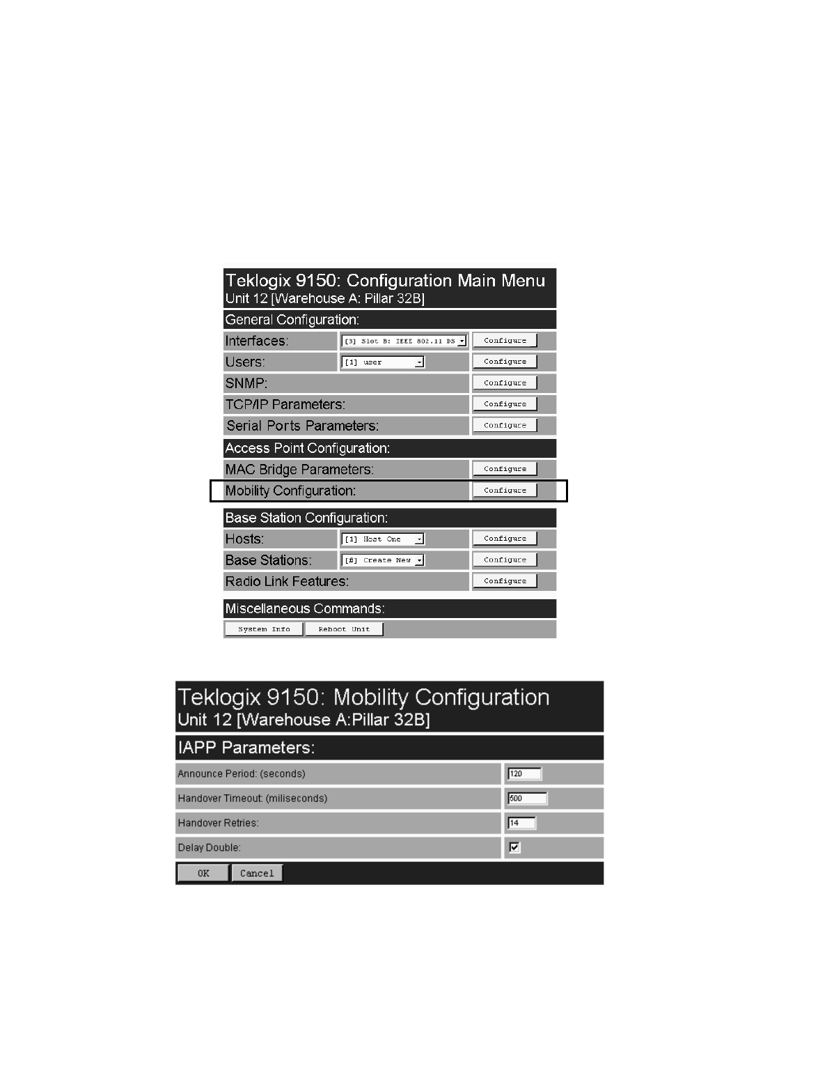
Chapter 6: Access Point Configuration
Mobility Configuration
140 Teklogix 9150 Wireless Gateway User Manual
6.4 Mobility Configuration
The Mobility Configuration page is entered from the Access Point Configuration
menu on the first page.
Going to the Mobility Configuration page opens the IAPP Parameters options.

Teklogix 9150 Wireless Gateway User Manual 141
Chapter 6: Access Point Configuration
Mobility Configuration
The Inter-Access Point Protocol (IAPP) is an extension to the IEEE 802.11 protocol.
In a multiple-9150 system, IAPP facilitates roaming of mobile stations among the
9150s, and enables communication and awareness between the 9150s. Every termi-
nal is associated with one 9150, but it can reassociate with another 9150 to maintain
uninterrupted communications. The association is “handed over” from one 9150 to
the next. The newly-associated 9150 will receive the terminal’s data frames and pass
them onto the LAN. Returning frames are no longer accepted by the original 9150,
which has disassociated from that terminal. Returning frames are now accepted by
the newly-associated 9150 and passed over the RF to the terminal. To implement
these procedures and coordinate the 9150s, IAPP specifies two message types:
Announce and Handover.
In IAPP Announce procedures, when the 9150 is initialized, it sends an IP multicast
message to inform the other 9150s in the network that it has become active. It also
informs the other 9150s of its continued operation (‘alive’ status) by periodically
multicasting the Announce beacon.
The Handover protocol is intended to inform the old 9150 that a terminal has been
associated with a new 9150, and to update the filter tables of intermediate MAC-
bridges to correctly forward frames destined for the terminal. The newly-associated
9150 sends a Handover request to the old 9150, which disassociates itself and
acknowledges the request.
Important: These parameters are set with optimum default values. Do not
adjust these values without discussing the effects with your
Teklogix representative.

Chapter 6: Access Point Configuration
IAPP Parameters
142 Teklogix 9150 Wireless Gateway User Manual
6.4.1 IAPP Parameters
Announce Period
The Announce Period parameter indicates the number of seconds between
Announce broadcasts. For further information, see “Mobility Configuration” on
page 140.
Handover Timeout
If there is no response to the Handover request by the 9150 within the time specified
in the Handover Timeout parameter, the request is retransmitted. If no response is
received after a number of retries (set in the Handover Retries parameter, below),
the 9150 will complete the reassociation procedure itself. For further information,
see “Mobility Configuration” on page 140.
Handover Retries
This parameter sets the number of times the 9150 will transmit a Handover request
to the disassociated 9150, before it completes the association transfer itself. See also
Handover Timeout, above.
Delay Double
The Delay Double parameter doubles the amount of Handover Timeout between
Handover Retries. For example, if the first retry is after 500 milliseconds, the next
Handover request is sent after 1 second, followed by a retry after 2 seconds, etc.

Teklogix 9150 Wireless Gateway User Manual 143
SPECIFICATIONS 7
7.1 Specifications For The 9150 Wireless Gateway.........145
7.1.1 PC Card Radios..................145
7.1.2 Power Requirements................147
7.1.3 Physical Description................147
7.1.4 Processor And Memory..............147
7.1.5 Environmental Requirements . . . . . . . . . . . 147
7.1.6 Network Interfaces.................147
7.1.7 SLIM Cards....................148
7.1.8 Approvals .....................148

Teklogix 9150 Wireless Gateway User Manual 145
Chapter 7: Specifications
Specifications For The 9150 Wireless Gateway
Note: Performance specifications are nominal and subject to change
without notice.
7.1 Specifications For The 9150 Wireless Gateway
7.1.1 PC Card Radios
Important: For sites in Canada, Lucent WaveLAN 802.11 and Proxim Range-
LAN 802.11 radios require a radio licence, unless they are installed
totally within a building. (The user shall obtain this licence from
Industry Canada.)
TRX7370 Narrow Band DSP
Transmit Power 2.0 Watts (North America)
0.5 to 2.0 Watts (International)
Frequency Range 403 to 512 MHz
Data Rate 9600 bps
No. of Channels 20
TekLAN 902 MHz DS Spread Spectrum (TRX7410)
Transmit Power 0.25 Watts (United States)
1.0 Watts (Canada and Australia)
Frequency 902 MHz
Data Rate 122 kbps
No. of Channels 7
TekLAN 2.4 GHz DS Spread Spectrum (TRX7425)
Transmit Power 0.1 Watt
Frequency Range 2.412 to 2.462 GHz
Data Rate 1 Mbps
No. of Channels 7
Chapter 7: Specifications
PC Card Radios
146 Teklogix 9150 Wireless Gateway User Manual
Proxim RangeLAN802 IEEE 802.11 FHSS 2.4 GHz (TRX7440)
Transmit Power 100 mW, 400 mW (XR)
Frequency 2.4 GHz
Data Rate 2 Mbps
No. of Channels 79 (FCC, ETSI) 35 (FR)
23 (JP) 27 (SP)
Lucent WaveLAN IEEE 802.11 DSSS 2.4 GHz (TRX7430)*
Transmit Power 32 mW
Frequency Range 2.4 to 2.4835 GHz
Data Rate 2 Mbps
No. of Channels 11 (FCC) 13 (ETSI)
4 (FR) 1 (JP)
2 (SP)
Lucent WaveLAN IEEE 802.11 2.4 GHz (TRX7431)*
Transmitter Power 32 mW
Frequency Range 2.4 to 2.4835 GHz
Data Rate 11 Mbps
No. of Channels 11 (FCC) 13 (ETSI)
4 (FR) 1 (JP)
2 (SP)
* For regulatory information concerning the Lucent WaveLAN PC Card, please
see page 149.
Teklogix 9150 Wireless Gateway User Manual 147
Chapter 7: Specifications
Power Requirements
7.1.2 Power Requirements
Input voltage 100 - 240 V
Frequency 50/60 Hz
Current 1.0 A
7.1.3 Physical Description
Enclosure Bayer Makroblend EL-700 (PC/PET
blend), jet black in colour, texture to
MT-11030 or equivalent
Dimensions Nominal 36.3 x 26.2 x 7.4 cm (14.3 x 10.3 x 2.9 in.)
Maximum 36.8 x 26.7 x 7.6 cm (14.5 x 10.5 x 3.0 in.)
Weight Nominal 2.9 kg (6.5 pounds)
Maximum 3.2 kg (7.0 pounds)
7.1.4 Processor And Memory
Power PC 860DC, 40 MHz Processor
16 MB DRAM
2 MB Flash ROM
7.1.5 Environmental Requirements
Operating Temperature 0°C to 50°C (32°F to 122°F)
Operating Rel. Humidity 10% to 90% (Non-condensing)
Storage Temperature -40°C to 70°C (-40°F to 158°F)
Dust and Rain IEC 529 IP42
7.1.6 Network Interfaces
On-Board Ethernet 10Base5
10Base2
10Base-T
Token Ring Madge Token Ring Smart 16/4 Ringnode
Adapter Type II PC card, 4 or 16 Mbps
Chapter 7: Specifications
SLIM Cards
148 Teklogix 9150 Wireless Gateway User Manual
7.1.7 SLIM Cards
Options RS-232/20 mA Current Loop
Optically isolated RS-232 Plus
7.1.8 Approvals
FCC Part 15, subpart B, Class B
Electrical Safety: CSA/NRTL, TÜV, CB Scheme
CE Mark
ETS 300 113
ETS 300 086
ETS 300 220
ETS 300 328

Teklogix 9150 Wireless Gateway User Manual 149
Chapter 7: Specifications
Approvals
Lucent WaveLAN PC Card Regulatory Information
The IEEE 802.11 WaveLAN PC Card must be installed and used in strict accor-
dance with the manufacturer’s instructions. This device complies with the following
radio frequency and safety standards.
Canada - Industry Canada (IC)
This device complies with RSS 210 of Industry Canada.
Europe - EU Declaration of Conformity
This device complies with the specifications listed below, following the provisions
of the EMC Directive 89/336/EEC:
•ETS 300-826 General EMC requirements for Radio equipment.
•ETS 300-328 Technical requirements for Radio equipment.
USA - Federal Communications Commission (FCC)
This device complies with Part 15 of FCC Rules. Operation of the devices in a
WaveLAN System is subject to the following two conditions:
•This device may not cause harmful interference.
•This device must accept any interference that may cause
undesired operation.
Important: Exposure to Radio Frequency Radiation.
The radiated output power of the IEEE 802.11 WaveLAN PC Card is far
below the FCC radio frequency exposure limits. Nevertheless, the
WaveLAN PC Card shall be used in such a manner that the potential for
human contact during normal operation is minimized. When using this
device in combination with WaveLAN Outdoor Antenna products, a
certain separation distance between antenna and nearby persons has to be
kept to ensure RF exposure compliance. Refer to the Regulatory State-
ments as identified in the documentation that comes with those products
for additional information.
Chapter 7: Specifications
Approvals
150 Teklogix 9150 Wireless Gateway User Manual
Interference Statement
This equipment has been tested and found to comply with the limits for a Class B
digital device, pursuant to Part 15 of the FCC Rules. These limits are designed to
provide reasonable protection against harmful interference in a residential
installation.
This equipment generates, uses, and can radiate radio frequency energy. If not
installed and used in accordance with the instructions, it may cause harmful interfer-
ence to radio communications. However, there is no guarantee that interference will
not occur in a particular installation.
If this equipment does cause harmful interference to radio or television reception,
which can be determined by turning the equipment off and on, the user is encour-
aged to try and correct the interference by one or more of the following measures:
•Reorient or relocate the receiving antenna.
•Increase the distance between the equipment and the receiver.
•Connect the equipment to an outlet on a circuit different from that to which
the receiver is connected.
•Consult the dealer or an experienced radio/TV technician for help.
Lucent Technologies is not responsible for any radio or television interference
caused by unauthorized modification of the devices included with this IEEE 802.11
WaveLAN Kit, or the substitution or attachment of connecting cables and equip-
ment other than specified by Lucent Technologies.
The correction of interference caused by such unauthorized modification, substitu-
tion or attachment will be the responsibility of the user.
For country-specific approvals, please consult the flyer “Radio Certification Infor-
mation” that is included with the 9150 Wireless Gateway.

Teklogix 9150 Wireless Gateway User Manual A-1
APPENDIX A
PORT PINOUTS AND CABLE DIAGRAMS
A.1 Console Port
* always pulled high
A.2 RS-232 Plus Port (SLIM Card)
Pin No. Name Function Direction
3 TD Transmit Data Out
2 RD Receive Data In
5 SG Signal Ground –
4* DTR Data Terminal Ready Out
7* RTS Request to Send Out
Pin No. Name Function Direction
1 FG Frame Ground –
2 TD Transmit Data Out
3 RD Receive Data In
7 SG Signal Ground –

Appendix A: Port Pinouts And Cable Diagrams
RS-232/Current Loop Port (SLIM Card)
A-2 Teklogix 9150 Wireless Gateway User Manual
A.3 RS-232/Current Loop Port (SLIM Card)
Pin No. Name Function Direction
1 FG Frame Ground –
2 TD Transmit Data Out
3 RD Receive Data In
4 RTS Request to Send Out
5 CTS Clear to Send In
6 DSR Data Set Ready In
7 SG Signal Ground –
8 DCD Data Carrier Detect In
12 –20 mA Current Loop In
13 –20 mA Current Loop In
14 –20 mA Out Out
19 –Loop Enable Out
20 DTR Data Terminal Ready Out

Teklogix 9150 Wireless Gateway User Manual A-3
Appendix A: Port Pinouts And Cable Diagrams
DA15 Connector Pinout (10Base5 Ethernet)
A.4 DA15 Connector Pinout (10Base5 Ethernet)
Pin No. Function Direction
1 Signal Ground –
2 Collision + In
3 Transmit + Out
4 Signal Ground –
5 Receive + In
6 Signal Ground –
7 No Connection –
8 Signal Ground –
9 Collision - In
10 Transmit - Out
11 Signal Ground –
12 Receive - In
13 +12 Volt Supply Out
14 Signal Ground –
15 No Connection –
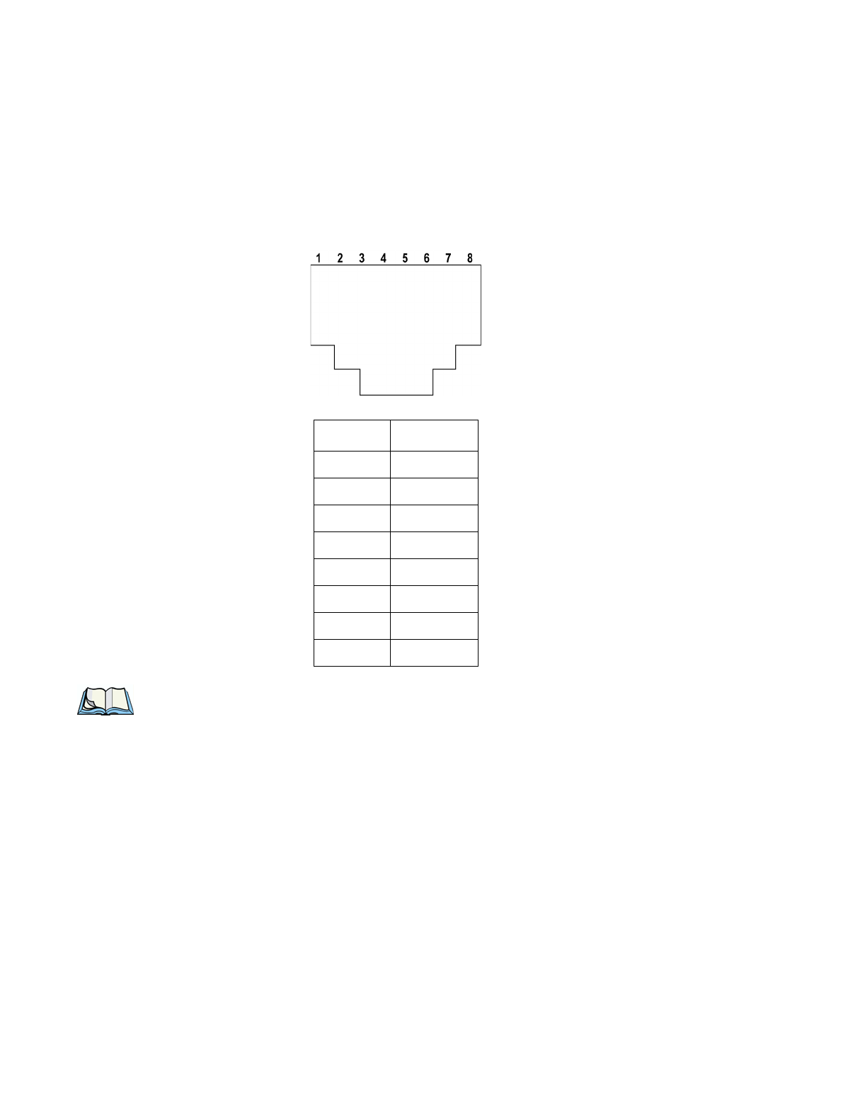
Appendix A: Port Pinouts And Cable Diagrams
RJ-45 Connector Pinouts (10Base-T Ethernet)
A-4 Teklogix 9150 Wireless Gateway User Manual
A.5 RJ-45 Connector Pinouts (10Base-T Ethernet)
Note: Usually, a straight-through connection is needed to connect Twisted-Pair
(10Base-T) to the hub.
Contact Signal
1TD+
2TD
–
3RD+
4 Not used
5 Not used
6RD
–
7 Not used
8 Not used

Teklogix 9150 Wireless Gateway User Manual A-5
Appendix A: Port Pinouts And Cable Diagrams
Token Ring Dsub9 Connector
A.6 Token Ring Dsub9 Connector
* This connection supports Shielded Twisted Pair (IBM STP) cable Type 1 or 6.
Pin No. Function Direction
1 Ring Input (A) In
2 Frame Ground –
3 +5 Volt Supply Out
4 Frame Ground –
5 Ring Output (B) Out
6 Ring Input (B) In
7 Frame Ground –
8 Frame Ground –
9 Ring Output (A) Out
Appendix A: Port Pinouts And Cable Diagrams
Serial Cable Descriptions
A-6 Teklogix 9150 Wireless Gateway User Manual
A.7 Serial Cable Descriptions
DTE to DTE Cable No. 16590
Cable No. Function Connection Standard
Length
16590 9400/9300 to 9150 Direct RS-232 15 feet
16598 9400/9300 to 9150 Modem RS-232 8 feet
16599 9400/9300 to 9150 Current Loop 15 feet
19387 9150 to Console Direct 6 feet
Teklogix 9150 Wireless Gateway User Manual A-7
Appendix A: Port Pinouts And Cable Diagrams
Serial Cable Descriptions
DTE to DCE Cable No. 16598
Current Loop Cable No. 16599
Appendix A: Port Pinouts And Cable Diagrams
Serial Cable Descriptions
A-8 Teklogix 9150 Wireless Gateway User Manual
Console Port Cable No. 19387

Teklogix 9150 Wireless Gateway User Manual B-1
APPENDIX B
MAC BRIDGE PROTOCOL FILTERS AND OUIS
B.1 Ethernet II Types (RFC 1700)
B.1.1 Listing by Description
DESCRIPTION TYPE (HEX VALUES)
3Com Corporation 0x6010-0x6014
3Com(Bridge) loop detect 0x9003
3Com(Bridge) TCP-IP Sys 0x9002
3Com(Bridge) XNS Sys Mgmt 0x9001
Advanced Encryption System 0x823E-0x8240
Aeonic Systems 0x8036
Allen-Bradley 0x80E0-0x80E3
Alpha Micro 0x814A
Apollo Computer 0x80F7
Apollo Computers 0x8019
Appletalk 0x809B
AppleTalk AARP (Kinetics) 0x80F3
Applitek Corporation 0x80C7
Apricot Computers 0x81CC-0x81D5
ARAI Bunkichi 0x81A4
ARP 0x0806
Artisoft 0x81D6-0x81DD
Ascom Banking Systems 0x8221-0x8222

Appendix B: MAC Bridge Protocol Filters and OUIs
Ethernet II Types (RFC 1700)
B-2 Teklogix 9150 Wireless Gateway User Manual
AT&T 0x8008
AT&T 0x8046
AT&T 0x8047
AT&T 0x8069
Athena Programming 0x827F-0x8282
ATOMIC 0x86DF
Autophon 0x806A
Banyan Systems 0x0BAD
Banyan Systems 0x80C4
Banyan Systems 0x80C5
BBN Simnet 0x5208
BBN VITAL-LanBridge cache 0xFF00
Berkeley Trailer encap/IP 0x1001-0x100F
Berkeley Trailer nego 0x1000
BIIN 0x814D
BIIN 0x814E
Bridge Communications 0x8132-0x8136
Cabletron 0x7034
Chaosnet 0x0804
Charles River Data System 0x8164-0x8166
Charles River Data System 0x8263-0x826A
ComDesign 0x806C
Computer Network Tech 0x869E-0x86A1
Computer Protocol Pty Ltd. 0x815C-0x815E
Computgraphic Corp. 0x806D
Comsat Labs 0x81F0-0x81F2
DESCRIPTION TYPE (HEX VALUES)

Teklogix 9150 Wireless Gateway User Manual B-3
Appendix B: MAC Bridge Protocol Filters and OUIs
Ethernet II Types (RFC 1700)
Counterpoint Computers 0x8062
Counterpoint Computers 0x8081-0x8083
Cronus Direct 0x8004
Cronus VLN 0x8003
Dansk Data Elektronik 0x807B
Datability 0x809C-0x809E
Datability 0x80E4-0x80F0
DCA Data Exchange Cluster 0x80C0-0x80C3
DEC Customer Protocol 0x6006
DEC DECNET Phase IV Route 0x6003
DEC Diagnostic Protocol 0x6005
DEC Ethernet Encryption 0x803D
DEC LAN Traffic Monitor 0x803F
DEC LANBridge 0x8038
DEC LAT 0x6004
DEC LAVC, SCA 0x6007
DEC MOP Dump/Load 0x6001
DEC MOP Remote Console 0x6002
DEC Unassigned 0x6008-0x6009
DEC Unassigned 0x8039-0x803C
DEC Unassigned 0x803E
DEC Unassigned 0x8040-0x8042
DEC Unassigned (Exp.) 0x6000
Delta Controls 0x86DE
DLOG 0x0660
DLOG 0x0661
DESCRIPTION TYPE (HEX VALUES)

Appendix B: MAC Bridge Protocol Filters and OUIs
Ethernet II Types (RFC 1700)
B-4 Teklogix 9150 Wireless Gateway User Manual
ECMA Internet 0x0803
Evans & Sutherland 0x805D
Excelan 0x8010
ExperData 0x8049
Gateway Communications 0x86A3-0x86AC
General Dynamics 0x8068
Harris Corporation 0x80CD-0x80CE
Hayes Microcomputers 0x8130
HP Probe 0x8005
IBM SNA Service on Ether 0x80D5
Idea Courier 0x8694-0x869D
Inst Ind Info Tech 0x829A-0x829B
Integrated Solutions TRFS 0x80DE-0x80DF
Intergraph Corporation 0x80C8-0x80CC
Internet IP (IPv4) 0x0800
Invisible Software 0x8A96-0x8A97
ISC Bunker Ramo 0xFF00-0xFF0F
Kinetics 0x80F4-0x80F5
KTI 0x8139-0x813D
Landis & Gyr Powers 0x86E0-0x86EF
Landmark Graphics Corp. 0x806E-0x8077
Little Machines 0x8060
Logicraft 0x8148
Loopback 0x9000
LRT 0x7020-0x7029
Matra 0x807A
DESCRIPTION TYPE (HEX VALUES)

Teklogix 9150 Wireless Gateway User Manual B-5
Appendix B: MAC Bridge Protocol Filters and OUIs
Ethernet II Types (RFC 1700)
Merit Internodal 0x807C
Motorola 0x8700-0x8710
Motorola Computer 0x818D
NBS Internet 0x0802
Nestar 0x8006
Network Computing Devices 0x8149
Nixdorf Computers 0x80A3
Novell, Inc. 0x8137-0x8138
Pacer Software 0x80C6
PCS Basic Block Protocol 0x4242
Planning Research Corp. 0x8044
Polygon 0x81E6-0x81EF
Proteon 0x7030
Protocol Engines 0x817D-0x818C
PUP Addr Trans 0x0A01
Qualcomm 0x8151-0x8153
Qualcomm 0x819A-0x81A3
Quantum Software 0x8203-0x8205
RAD Network Devices 0x81A5-0x81AE
Rational Corp 0x8150
Retix 0x80F2
Reverse ARP 0x8035
Rosemount Corporation 0x80D3-0x80D4
SAIC 0x81F3-0x81F5
SECTRA 0x86DB
SGI bounce server 0x8016
DESCRIPTION TYPE (HEX VALUES)

Appendix B: MAC Bridge Protocol Filters and OUIs
Ethernet II Types (RFC 1700)
B-6 Teklogix 9150 Wireless Gateway User Manual
SGI diagnostics 0x8013
SGI network games 0x8014
SGI reserved 0x8015
Siemens Gammasonics Inc. 0x80A4-0x80B3
SNMP 0x814C
Spider Systems Ltd. 0x809F
Stanford V Kernel exp. 0x805B
Stanford V Kernel prod. 0x805C
Symbolics Private 0x081C
Symbolics Private 0x8107-0x8109
Taurus Controls 0x829C-0x82AB
Taylor Instrument 0x80CF-0x80D2
Technically Elite Concept 0x814F
Tigan, Inc. 0x802F
Tymshare 0x802E
Ungermann-Bass dia/loop 0x7002
Ungermann-Bass download 0x7000
Ungermann-Bass net debugr 0x0900
Univ. of Mass. @ Amherst 0x8065
Univ. of Mass. @ Amherst 0x8066
Valid Systems 0x1600
Varian Associates 0x80DD
Veeco Integrated Auto. 0x8067
VG Analytical 0x81F6-0x81F8
VG Laboratory Systems 0x8131
Vitalink Communications 0x807D-0x807F
DESCRIPTION TYPE (HEX VALUES)

Teklogix 9150 Wireless Gateway User Manual B-7
Appendix B: MAC Bridge Protocol Filters and OUIs
Ethernet II Types (RFC 1700)
Vitalink TransLAN III 0x8080
Walker Richer & Quinn 0x82AC-0x8693
Wellfleet Communications 0x80FF-0x8103
X.25 Level 3 0x0805
X.75 Internet 0x0801
Xerox IEEE802.3 PUP 0x0A00
XEROX NS IDP 0x0600
XNS Compatibility 0x0807
Xyplex 0x0888-0x088A
Xyplex 0x81B7-0x81B9
DESCRIPTION TYPE (HEX VALUES)

Appendix B: MAC Bridge Protocol Filters and OUIs
Ethernet II Types (RFC 1700)
B-8 Teklogix 9150 Wireless Gateway User Manual
B.1.2 Listing By Type (Hexadecimal)
TYPE (HEX VALUES) DESCRIPTION
0x0600 XEROX NS IDP
0x0660 DLOG
0x0661 DLOG
0x0800 Internet IP (IPv4)
0x0801 X.75 Internet
0x0802 NBS Internet
0x0803 ECMA Internet
0x0804 Chaosnet
0x0805 X.25 Level 3
0x0806 ARP
0x0807 XNS Compatibility
0x081C Symbolics Private
0x0888-0x088A Xyplex
0x0900 Ungermann-Bass net debugr
0x0A00 Xerox IEEE802.3 PUP
0x0A01 PUP Addr Trans
0x0BAD Banyan Systems
0x1000 Berkeley Trailer nego
0x1001-0x100F Berkeley Trailer encap/IP
0x1600 Valid Systems
0x4242 PCS Basic Block Protocol
0x5208 BBN Simnet
0x6000 DEC Unassigned (Exp.)
0x6001 DEC MOP Dump/Load
0x6002 DEC MOP Remote Console

Teklogix 9150 Wireless Gateway User Manual B-9
Appendix B: MAC Bridge Protocol Filters and OUIs
Ethernet II Types (RFC 1700)
0x6003 DEC DECNET Phase IV Route
0x6004 DEC LAT
0x6005 DEC Diagnostic Protocol
0x6006 DEC Customer Protocol
0x6007 DEC LAVC, SCA
0x6008- DEC Unassigned
0x6009 DEC Unassigned
0x6010-0x6014 3Com Corporation
0x7000 Ungermann-Bass download
0x7002 Ungermann-Bass dia/loop
0x7020-0x7029 LRT
0x7030 Proteon
0x7034 Cabletron
0x8003 Cronus VLN
0x8004 Cronus Direct
0x8005 HP Probe
0x8006 Nestar
0x8008 AT&T
0x8010 Excelan
0x8013 SGI diagnostics
0x8014 SGI network games
0x8015 SGI reserved
0x8016 SGI bounce server
0x8019 Apollo Computers
0x802E Tymshare
0x802F Tigan, Inc.
TYPE (HEX VALUES) DESCRIPTION

Appendix B: MAC Bridge Protocol Filters and OUIs
Ethernet II Types (RFC 1700)
B-10 Teklogix 9150 Wireless Gateway User Manual
0x8035 Reverse ARP
0x8036 Aeonic Systems
0x8038 DEC LANBridge
0x8039-0x803C DEC Unassigned
0x803D DEC Ethernet Encryption
0x803E DEC Unassigned
0x803F DEC LAN Traffic Monitor
0x8040-0x8042 DEC Unassigned
0x8044 Planning Research Corp.
0x8046 AT&T
0x8047 AT&T
0x8049 ExperData
0x805B Stanford V Kernel exp.
0x805C Stanford V Kernel prod.
0x805D Evans & Sutherland
0x8060 Little Machines
0x8062 Counterpoint Computers
0x8065 Univ. of Mass. @ Amherst
0x8066 Univ. of Mass. @ Amherst
0x8067 Veeco Integrated Auto.
0x8068 General Dynamics
0x8069 AT&T
0x806A Autophon
0x806C ComDesign
0x806D Computgraphic Corp.
0x806E-0x8077 Landmark Graphics Corp.
TYPE (HEX VALUES) DESCRIPTION

Teklogix 9150 Wireless Gateway User Manual B-11
Appendix B: MAC Bridge Protocol Filters and OUIs
Ethernet II Types (RFC 1700)
0x807A Matra
0x807B Dansk Data Elektronik
0x807C Merit Internodal
0x807D-0x807F Vitalink Communications
0x8080 Vitalink TransLAN III
0x8081-0x8083 Counterpoint Computers
0x809B Appletalk
0x809C-0x809E Datability
0x809F Spider Systems Ltd.
0x80A3 Nixdorf Computers
0x80A4-0x80B3 Siemens Gammasonics Inc.
0x80C0-0x80C3 DCA Data Exchange Cluster
0x80C4 Banyan Systems
0x80C5 Banyan Systems
0x80C6 Pacer Software
0x80C7 Applitek Corporation
0x80C8-0x80CC Intergraph Corporation
0x80CD-0x80CE Harris Corporation
0x80CF-0x80D2 Taylor Instrument
0x80D3-0x80D4 Rosemount Corporation
0x80D5 IBM SNA Service on Ether
0x80DD Varian Associates
0x80DE-0x80DF Integrated Solutions TRFS
0x80E0-0x80E3 Allen-Bradley
0x80E4-0x80F0 Datability
0x80F2 Retix
TYPE (HEX VALUES) DESCRIPTION

Appendix B: MAC Bridge Protocol Filters and OUIs
Ethernet II Types (RFC 1700)
B-12 Teklogix 9150 Wireless Gateway User Manual
0x80F3 AppleTalk AARP (Kinetics)
0x80F4-0x80F5 Kinetics
0x80F7 Apollo Computer
0x80FF-0x8103 Wellfleet Communications
0x8107-0x8109 Symbolics Private
0x8130 Hayes Microcomputers
0x8131 VG Laboratory Systems
0x8132-0x8136 Bridge Communications
0x8137-0x8138 Novell, Inc.
0x8139-0x813D KTI
0x8148 Logicraft
0x8149 Network Computing Devices
0x814A Alpha Micro
0x814C SNMP
0x814D BIIN
0x814E BIIN
0x814F Technically Elite Concept
0x8150 Rational Corp
0x8151-0x8153 Qualcomm
0x815C-0x815E Computer Protocol Pty Ltd
0x8164-0x8166 Charles River Data System
0x817D-0x818C Protocol Engines
0x818D Motorola Computer
0x819A-0x81A3 Qualcomm
0x81A4 ARAI Bunkichi
0x81A5-0x81AE RAD Network Devices
TYPE (HEX VALUES) DESCRIPTION

Teklogix 9150 Wireless Gateway User Manual B-13
Appendix B: MAC Bridge Protocol Filters and OUIs
Ethernet II Types (RFC 1700)
0x81B7-0x81B9 Xyplex
0x81CC-0x81D5 Apricot Computers
0x81D6-0x81DD Artisoft
0x81E6-0x81EF Polygon
0x81F0-0x81F2 Comsat Labs
0x81F3-0x81F5 SAIC
0x81F6-0x81F8 VG Analytical
0x8203-0x8205 Quantum Software
0x8221-0x8222 Ascom Banking Systems
0x823E-0x8240 Advanced Encryption System
0x827F-0x8282 Athena Programming
0x8263-0x826A Charles River Data System
0x829A-0x829B Inst Ind Info Tech
0x829C-0x82AB Taurus Controls
0x82AC-0x8693 Walker Richer & Quinn
0x8694-0x869D Idea Courier
0x869E-0x86A1 Computer Network Tech
0x86A3-0x86AC Gateway Communications
0x86DB SECTRA
0x86DE Delta Controls
0x86DF ATOMIC
0x86E0-0x86EF Landis & Gyr Powers
0x8700-0x8710 Motorola
0x8A96-0x8A97 Invisible Software
0x9000 Loopback
0x9001 3Com(Bridge) XNS Sys Mgmt
TYPE (HEX VALUES) DESCRIPTION

Appendix B: MAC Bridge Protocol Filters and OUIs
DSAP/SSAP Types
B-14 Teklogix 9150 Wireless Gateway User Manual
B.2 DSAP/SSAP Types
0x9002 3Com(Bridge) TCP-IP Sys
0x9003 3Com(Bridge) loop detect
0xFF00 BBN VITAL-LanBridge cache
0xFF00-0xFF0F ISC Bunker Ramo
DSAP/SSAP
(HEX VALUES) DESCRIPTION
0x0404 SNA Path Control
0x0505 SNA
0x0606 reserved (DOD IP)
0x0808 SNA
0x0C0C SNA
0x0E0E PROWAY-LAN network management and initialization (ISA-S72)
0x4242 MAC Bridge Spanning Tree Protocol (IEEE 802.1D-1993)
0x4E4E MAP messaging service (EIA RS-511)
0x5E5E ISI IP
0x8E8E PROWAY-LAN active station list maintenance (ISA-S72)
0xAAAA Subnetwork Access Protocol (SNAP)
0xE0E0 Novell Netware
0xF0F0 NetBIOS
0xFEFE ISO network layer protocol (ISO CLNS DIS 8473)
TYPE (HEX VALUES) DESCRIPTION

Teklogix 9150 Wireless Gateway User Manual B-15
Appendix B: MAC Bridge Protocol Filters and OUIs
OUI Values
B.3 OUI Values
A few important OUI values:
OUI (HEX VALUES) DESCRIPTION
0x000000 RFC 1042 encapsulation
0x0000F8 Bridge-Tunnel encapsulation
0x0020A6 Proxim Inc.
0x00601D Lucent Technologies
0x00C0AF Teklogix Inc.


Teklogix 9150 Wireless Gateway User Manual I
BOLDFACE indicates a menu or sub-menu name; Boldface indicates a parameter name.
INDEX
A
ACCESS POINT CONFIGURATION
MAC Bridge Parameters 129–139
Address Filters 132
General Configuration 131
Protocol Filters 133
Mobility Configuration 140–142
access point configuration 10, 41,
125–142
Action
Ethernet II filters 136
LLC filters 137
SNAP filters 138
Active Channel
TekLAN 51
TRX7370 parameters 60
Actively Negotiate with Host
3274 Telnet Protocol 97
5250 Telnet Protocol 111
Actual IP Address
Ethernet 31
Token Ring 33
Actual Subnet Mask
Ethernet 31
Token Ring 33
Adaptive polling/contention protocol 8
addresses, network 36–37
Address Filters 132
Address Filters Enabled, MAC Bridge
parameters 131
AIAG
3274 Emulation 90
5250 Emulation 104
Alarm
3274 Emulation 86
5250 Emulation 100
Announce (IAPP message) 141
Announce Period 142
ANSI
compatible terminals, connecting 21
parameter 115
ANSI/Telnet 113–115
antenna requirements 16, 17
approvals 147
Auto-login, ANSI Telnet
Auto-telnet/login Enable 118
failed login 120
Password 119
User ID 119
Auto Startup
Narrow Band, TRX7370 55
TekLAN 51
Auto-Startup 72
Auto-telnet, ANSI Telnet
Auto-telnet/login Enable 118
Host 119
Terminal Prompt 119
B
Barcode
3274 Emulation 94
5250 Emulation 109
Base
Number, Wlan 52
Priority, Wlan 53
base station
configuration 41, 45–53
IP Address 71
Name 71
wireless 47
BASE STATIONS 71
baud rate
ports 20
baud rates
console port 40
serial port 40
baud rate See Data Rate
BOOTP, TCP/IP 38
bootptab file 38
Bootstrap Protocol (BOOTP) 38
broadcast storm 139

Index
II Teklogix 9150 Wireless Gateway User Manual
BOLDFACE indicates a menu or sub-menu name; Boldface indicates a parameter name.
C
cables
coaxial 17
console
port No. 19387 A-8
Current Loop No. 16599 A-7
diagrams A-6, A-7
DTE to DTE #16590 A-6
DTE to DTE #16598 A-7
ground problems 21
maximum length – RS-232 Plus, Current
Loop 20
outdoor data cable 21
part numbers 20
serial descriptions A-6
Callsign Period, narrow band radio 58
Callsign String, narrow band radio 58
cellular base 8, 72
Channel, IEEE 802.11 DS 128
Channel n Enabled, TekLAN 51
channels (Narrow Band) 60
Clear
3274 Emulation 86
5250 Emulation 100
Cold Start Trap 36
Collision Size, narrow band radio 57
Command Region
3274 Emulation 95
5250 Emulation 109
configuration
access point 10, 41, 125–142
base station 41, 45–53
general options 29
IEEE 802.11
DS 34, 128
FH 34, 126
main menu 25
mini-controller 41, 75–122
CONFIGURATION MAIN MENU 25
connecting
ANSI compatible terminals 21
Ethernet 19
Token Ring 19
video display terminal 21
connectors
DA15 A-3
RJ-45 A-4
Token Ring A-5
console
commands (IP) 25
connecting 21
port
cable No. 19387 A-8
pinouts A-1
Console Port, baud rate 40
Convert 7 to 8 Bits
ANSI Emulation 115
Current Loop
port 20
port pinouts A-2
Current Loop cable no. 16599 A-7
D
data rate
serial 21, 25
TekLAN
2.4 GHz 50
902 MHz 50
Data Rate, TekLAN radio 50
DA15 connector pinout A-3
DEC VT220, connecting 21
Default
Actual Gateway Address, bootp 38
Gateway Address, bootp 39
IP Address
Ethernet 31
Token Ring 33
Subnet Mask
Ethernet 31
Token Ring 33
Delay Double 142
directional antenna 16
Direct Sequence (DS) radios
all 7, 34
IEEE 802.11 10, 126, 128
specifications
IEEE 802.11 146
TekLAN 145
TekLAN
2.4 GHz 50, 51, 53
902 MHz 18, 50, 51
Direct TCP Connections for TekTerm
73
DNS 37–39
Default Domain 39
Name Server 39
Resolver Enabled 39
Domain Name System See DNS

Teklogix 9150 Wireless Gateway User Manual III
Index
BOLDFACE indicates a menu or sub-menu name; Boldface indicates a parameter name.
DRAM 147
DSAP/SSAP 137
DSAP/SSAP types (table) B-14, B-15
DTE to DCE cable No. 16598 A-7
DTE to DTE cable No. 16590 A-6
E
Echo
ANSI Emulation 114
electrical safety approvals 147
Employ bootp 19, 38
Emulation and Protocol 64
General Host menu 84
General Host menu, 9010 emulation
67
mini-controller configuration 80
emulations
ANSI/Telnet 113–115
overview 77
3274/Telnet 84–95
5250/Telnet 95–110
9010/Serial 69–70
9010/TCP/IP 67
Enable Card
Narrow Band, TRX7370 55
TekLAN 51
Enabled Channels
TRX7370 parameters 60
Entry Line
3274 Emulation 94
5250 Emulation 109
environmental requirements 15
operating relative humidity 147
operating temperature 147
overview 16
storage temperature 147
Escape Timeout
ANSI Emulation 114
ESSID
IEEE 802.11 DS 128
IEEE 802.11 FH 127
Ethernet
adaptor cards 147
base station 71
connections 19
Frame Types (diagram) 134
IP Parameters 31
packet size 19, 31
Physical Address 30
port pinout A-3
status indicator LED 18
10Base-T 19, A-4
10Base2 19
10Base5 19, A-3
Ethernet II
header 134
types (tables) B-1–B-14
Ethernet II Filters 136
external devices 17
F
Field Overhead
3274 Emulation 95
5250 Emulation 109
filters 131, 132
broadcast storm 139
Ethernet II 136
LLC 137
MAC bridge 133
PROTOCOL FILTERS 133
SNAP 138
First Local Terminal Port
ANSI Telnet Protocol 117
3274 Telnet Protocol 97
5250 Telnet Protocol 111
First Terminal Listen Port
ANSI Telnet Protocol 117
3274 Telnet Protocol 97
5250 Telnet Protocol 111
Free Window Factor, narrow band radio
57
Frequencies, narrow band radio 62
Frequency Hopping (FH) radio 7, 34, 126,
146
frequency See Range
Full Duplex Mode
9010 Serial Protocol Options 70
Function Key n
Function Key Mapping screens
ANSI 122
3274 98
5250 112
Function Key Remapping
ANSI Emulation 115
G
General Host Options
base stations 66

Index
IV Teklogix 9150 Wireless Gateway User Manual
BOLDFACE indicates a menu or sub-menu name; Boldface indicates a parameter name.
mini-controller 83
General Parameters, narrow band radio
62
ground problems, cables 21
H
Handover
Retries 142
Timeout 142
Handover (IAPP message) 141
header types
Ethernet II 134
LLC 134
SNAP 134
Hidden Match Character
3274 Emulation 93
5250 Emulation 108
Hopping
Pattern 127
Set 127
Host
Port
ANSI Telnet Protocol 117
3274 Telnet Protocol 96
5250 Telnet Protocol 110
Print
3274 Emulation 88
5250 Emulation 102
Table, DNS 37
Timeout, ANSI Emulation 113
HOST MENU
base station 65–70
mini-controller 82
Hosts
base station configuration 63
mini-controller configuration 80
I
IAPP 11, 140
messages
Announce 141
Handover 141
IAPP PARAMETERS
Announce Period 142
Delay Double 142
Handover Retries 142
Handover Timeout 142
IEEE 802.11
configurations 34, 126, 128
DSChannel 128
FHHopping Pattern 127
Hopping Set 127
protocol description 10
radios
Lucent WaveLAN IEEE 7, 126,
128, 146
Proxim RangeLAN802 7, 126, 128,
146
IEEE 802.11 (DIRECT SEQUENCE
RADIO PARAMETERS) 128
IEEE 802.11 (FREQUENCY HOPPING
RADIO PARAMETERS) 126
input voltage (power requirements) 16,
146
installation
environmental requirements 16, 147
LAN 18
Inter-Access Point Protocol See IAPP
INTERFACES
Ethernet 30
IEEE 802.11 126
main menu 30
narrow band 53–63
TekLAN 49–53
Token Ring 32
interfaces, network 147
Internet Explorer 21, 25
IP Address
base station 71
Host Table 37
IP address
configuring with console 25
9150 18
IP Parameters
Ethernet 31
Token Ring 33
Is Host Fujitsu
3274 Emulation 86
L
LAN installations 18
Last Active Session Key
ANSI Telnet Protocol 118
LEDs
Ethernet 18
PC card status 18

Teklogix 9150 Wireless Gateway User Manual V
Index
BOLDFACE indicates a menu or sub-menu name; Boldface indicates a parameter name.
SLIM card 18
TekLAN 18
Token Ring 18
TRX7370 18
Line Protocol
9010 Serial Protocol Options 69
LLC FILTERS 137
LLC header 134
Local
3274 Emulation 87
5250 Emulation 102
Local IP Address to Bind
ANSI Telnet Protocol 117
3274 Telnet Protocol 97
5250 Telnet Protocol 111
LSB (Least Significant Byte) 30
Lucent WaveLAN
IEEE 802.11 DSSS 2.4 GHz 128, 146
PC Card regulatory information 148
M
MAC
address 127, 128
Bridge Configuration menus (chart)
130
bridge parameters 129–139
layer 10
MAC Address 132
MAC BRIDGE PARAMETERS
129–139
Madge Token Ring PC card
specifications 147
maintenance requirements 16
Maximum Message Segment Size, narrow
band radio 57
Maximum Sessions per Terminal
ANSI Telnet Protocol 117
3274 Telnet Protocol 96
5250 Telnet Protocol 111
Max Priority, Wlan 52
Medium Access Control See MAC
memory 147
menus, accessing 27
Message
Duration, Wlan 53
Mode Limit, narrow band radio 58
Size 72
Microsoft Internet Explorer 21, 25
mini-controller
configuration 41, 75–122
emulations 77
networks 77
MISCELLANEOUS COMMANDS
42–43
MOBILITY CONFIGURATION
140–142
MSB (Most Significant Byte) 30
multicast storm 139
N
Name
DNS Host Table 37
Ethernet II filters 136
General Host menu
base stations 66
mini-controller 84
LLC filters 137
SNAP filters 138
narrow band radio 7
Active Channel parameter 60
configuration 34
Enabled Channels parameter 60
overview of menus 54
parameters 53–63
POLLING PROTOCOL
PARAMETERS 56
RADIO CHANNELS parameter 60
RADIO PARAMETERS 59
specifications 145
TRX7370 53–63
Netscape Navigator 21, 25
network
addresses 36–37
interfaces 147
Number of Poll Windows, narrow band
radio 56
Number of Retries, narrow band radio 57
O
Offline Timeout, Wlan 53
omnidirectional antenna 16
Onboard Ethernet 30
pinout (10Base-T) A-4
pinout (10Base5) A-3
online/offline messages 67, 69
Operate in Cellular Mode 72
operating
relative humidity 147

Index
VI Teklogix 9150 Wireless Gateway User Manual
BOLDFACE indicates a menu or sub-menu name; Boldface indicates a parameter name.
temperature 147
OUI 138
OUI values (table) B-15
P
packet size
Ethernet 31
Token ring 33
packet size, Ethernet 19
packet size, Token ring 19
Page
ANSI Emulation 115
Pages
3274 Emulation 89
5250 Emulation 104
parameters
changing configurations 25
changing with a web browser 21
MAC Bridge 129–139
radio 126–128
System Parameters 36
Passthru
3274 Emulation 86
5250 Emulation 101
password, default 27
PCMCIA cards
radio configurations 34
specifications 145–146
status indicator LEDs 18
802.11 DS 128
802.11 FH 126
Percent Polling Protocol Terminal
Timeout 73
PHY layer 10
physical
description 146
Physical Address 30, 127, 128
specifications 146
pinouts See port pinouts
Poll ID 73
POLLING PROTOCOL PARAME-
TERS
TRX7370 parameters 56
Polling Protocol Terminal Timeout 73
port
location 17
options 20
pinouts
console port A-1
Ethernet (10Base5) A-3
RJ-45 connector (10Base-T) A-4
RS-232/Current Loop port A-2
RS-232 Plus port A-1
Token Ring A-5
power requirements 16, 146
Print Form Length
3274 Emulation 94
5250 Emulation 108
Print Line
3274 Emulation 94
5250 Emulation 108
Procedures
3274 Emulation 87
5250 Emulation 102
processor 147
protocol
adaptive polling/contention 8
BOOTP 38
Protocol, base station Ethernet
connection 71
radio
adaptive polling/contention 8
IEEE 802.11 10
Wireless LAN (Wlan) 8
Protocol Default Action, MAC Bridge
parameters 132
PROTOCOL FILTERS 133
Ethernet II 136
LLC 137
SNAP 138
Storm Detection 139
Protocol Filters Enabled, MAC Bridge
parameters 131
Proxim
RangeLAN802 IEEE 802.11 FHSS 2.4
GHz 7, 146
R
radio
Lucent WaveLAN IEEE 802.11 DSSS
7, 146
options 7
parameters 126–128
PCMCIA cards 7, 145
Percent Polling Protocol Terminal
Timeout 73
Poll ID 73

Teklogix 9150 Wireless Gateway User Manual VII
Index
BOLDFACE indicates a menu or sub-menu name; Boldface indicates a parameter name.
Polling Protocol Terminal Timeout
73
protocols (Wlan, adaptive polling, IEEE
802.11) 7
Proxim RangeLAN802 IEEE 802.11
FHSS 7, 146
Range, TekLAN 51
specifications 145
IEEE 802.11 145
TekLAN
2.4 GHz 146
902 MHz 145
spread spectrum 7, 126, 128
TekLAN 145
2.4 GHz 7, 50
902 MHz 7, 50
TRX7370 Narrow Band DSP 7, 145
RADIO CHANNELS
TRX7370 parameters 60
RADIO LINK FEATURES 72–73
RADIO PARAMETERS, TRX7370 59
Radio Type, TekLAN 50
RAM 147
Range, TekLAN 51
RangeLAN 802 PCMCIA with Proxim
FHSS 2.4GHz Radio 7, 126, 146
Reboot Unit, Miscellaneous Commands
43
Refrain from sending On-line & Off-line
messages
9010/Serial emulation 69
9010/TCP/IP emulation 67
Regulatory Domain
IEEE 802.11 DS 128
IEEE 802.11 FH 127
Remote Print
3274 Emulation 89
5250 Emulation 103
Remote Txon, narrow band radio 59
Restart, Storm Detection 139
Retries, Number of 57
Ring Speed, Token Ring 32
RJ-45 connector pinouts (10Base-T
Ethernet) A-4
RLE, ANSI Emulation 115
ROM 147
RS-232/RS-232 Plus
port
pinouts A-1
port pinouts A-2
ports 20
RS-232 Current Loop
connectivity 20
specifications 147
RS-232 Plus
connectivity 20
specifications 147
S
safety
approvals 147
instructions viii
Send IAC Break as an Attention Key
3274 Telnet Protocol 97
Send IAC Interrupt Process as a System
Request
3274 Telnet Protocol 97
serial
base stations 6
connectivity 20
Line Protocol character codes 70
port pinouts A-1, A-2
specifications 147
status indicator LED 18
Serial I/O
3274 Emulation 94
5250 Emulation 108
Serial Port, baud rate 40
SERIAL PORTS PARAMETERS 40
Session Cycle Key
ANSI Telnet Protocol 118
Shared Channel
Narrow Band, TRX7370 55
Size of Poll Windows, narrow band radio
56
SLIM card See serial
Slot n
PC card 34
Token-Ring 32
SNAP, header 134
SNAP Filters 138
SNMP
menu 35
SNMP Communities 36
System Parameters 36
Trap Receivers 36
specifications
PCMCIA card radios 145–146

Index
VIII Teklogix 9150 Wireless Gateway User Manual
BOLDFACE indicates a menu or sub-menu name; Boldface indicates a parameter name.
physical 146
spread spectrum radios 7
IEEE 802.11 (2.4 GHz) 126, 128, 146
TekLAN 145, 146
status indicators (LEDs) 18
Storm Detection 139
Subnet Mask See Default Subnet Mask
Sync Delay, narrow band radio 59
System Info, Miscellaneous Commands
42
System Parameters, SNMP 36
T
TCP/IP PARAMETERS 36
TCP Session Request Key
ANSI Telnet Protocol 117
TekLAN
card 34
overview of menus 49
parameters 49–53
radio parameters 50–51
specifications 145
Wlan parameters 52–53
2.4 GHz DS Spread Spectrum 7, 50
902 MHz DS Spread Spectrum 7, 50
TekTerm 73
terminal
associating with 9150 140
connecting a video display 21
Terminal Range 65
General Host menu 84
General Host menu, 9010 emulation
67
mini-controller configuration 81
Terminal Type
ANSI Telnet Protocol 117
3274 Telnet Protocol 96
5250 Telnet Protocol 110
text conventions 4
Threshold
ANSI Emulation 114
Storm Detection 139
Timeout, Wlan 52
Token Ring 32
adaptor PC card specifications 19, 147
base station 6, 71
connections 19
IP Parameters 33
packet size 19, 33
port
pinout A-5
Ring Speed 32
status indicator LED 18
Transmit Line
3274 Emulation 90
5250 Emulation 104
Trap Receivers, SNMP 36
TRX7370 Narrow Band DSP radio See also
narrow band radio 7, 145
TRX7370 RADIO CARD
PARAMETERS 60
TRX7410 TekLAN radio 7, 145
TRX7425 TekLAN radio 7, 145
TRX7430 WaveLAN radio 7, 146
TRX7440 RangeLAN radio 7, 146
Tuning Values, narrow band radio 63
Type
Ethernet II filters 137
SNAP filters 138
U
Use Cyclic Redundancy Check (CRC)
9010 Serial Protocol Options 70
Use International EBCDIC
3274 Emulation 86
5250 Emulation 100
Use NS/NR
9010 Serial Protocol Options 70
user name, default 27
USERS 34
V
video display terminal, connecting 21
Visible Match Character
3274 Emulation 92
5250 Emulation 106
voltage, input 16, 146
W
web browser 21, 25
WIRELESS LAN (Wlan)
PARAMETERS 52–53
Wireless LAN (Wlan) protocol
cellular base considerations 72
description 8
Write Error Code
5250 Emulation 100

Teklogix 9150 Wireless Gateway User Manual IX
Index
BOLDFACE indicates a menu or sub-menu name; Boldface indicates a parameter name.
10Base-T Ethernet 19, A-4
10Base2 Ethernet 19
10Base5 Ethernet 19, A-3
2.4 GHz radios 145
3274/Telnet 84–95
5250/Telnet 95–110
9010 / Serial 68–70
9010 / TCP/IP 67
9010 Emulation Options
serial 69
TCP/IP 67
9010 Emulation Parameters 84
902 MHz radio 145
9400/9300 Network Controllers, cellular
mode 52, 72