Thomson Broadcast and Multimedia ULT-1K10K2 UHF Digital transmitter, for use with MediaFlo User Manual PREIMPAP
Thomson Broadcast & Multimedia, Inc. UHF Digital transmitter, for use with MediaFlo PREIMPAP
Contents
Operation manual part 1

45321648.01 104 A E
Numéro / Number Doc. Rev. Lan
g
u.
:
33
(
1
)
3
4.
90
.
3
2.
55
p
reliminar
y
: hotline
@
thale
s
-bm.com 16/06/2006 9946 V1
Digital Liquid Cooled UHF TV
Equipment
5K2 DD, MEDIAFLO SIRIUS
12089
Descriptive and Functional Manual

9946 V1
45321648.01 104 A E preliminary ii
Numéro / Number Doc. Rev. Lan
g
u. 16/06/2006 Pa
g
e
Information contained is this document is confidential, is THOMSON property and cannot be disclosed in whatever form without prior written authorization of THOMSON.
Table of content
1. Generale description ........................................................................................7
1.1. Outline ............................................................................................................. 7
1.2. Simplifier description of transmitter............................................................. 9
1.2.1. Basic operation ............................................................................................ 9
1.2.2. Architecture................................................................................................ 10
2. Detailed operational description ...................................................................13
2.1. Introduction................................................................................................... 13
2.2. Transmission function................................................................................. 14
2.2.1. Operational description of digital exciter.................................................... 14
2.2.2. Exciter change-over................................................................................... 15
2.2.3. ASI input change-over ............................................................................... 15
2.2.4. Amplification of the RF signal .................................................................... 16
2.3. Description of the overall transmitter control system.............................. 18
2.3.1. Introduction ................................................................................................ 18
2.3.2. Polling of events data ................................................................................ 18
2.3.3. Polling of operator commands................................................................... 21
2.3.4. Command control sytem............................................................................ 21
2.3.5. Processing of faults ................................................................................... 24
2.3.6. Computing the overall quality assessment of the RF signal...................... 28
2.3.7. Data transfer between exciter and CPU.................................................... 29
2.4. User interface operation .............................................................................. 30
2.4.1. Outline........................................................................................................ 30
2.4.2. Display control system............................................................................... 30
2.4.3. Power level bargraphs on PCL.................................................................. 33
2.4.4. Log book control system............................................................................ 34
2.4.5. On/Off commands and change-over override switch ................................ 34
3. Description / Test points / Location of units ................................................35
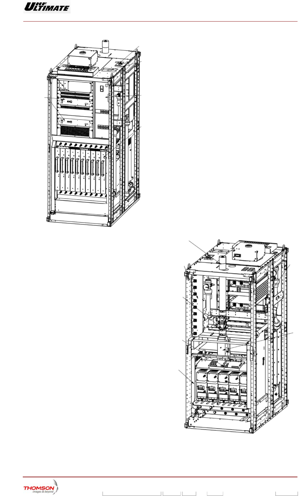
3.1. System architecture and location of transmitter units ............................. 35
3.1.1. Location of transmitter units....................................................................... 37
3.2. Rack : SIRIUS DVB-T UHF 45321627.11 ..................................................... 39

9946 V1
45321648.01 104 A E preliminary iii
Numéro / Number Doc. Rev. Lan
g
u. 16/06/2006 Pa
g
e
Information contained is this document is confidential, is THOMSON property and cannot be disclosed in whatever form without prior written authorization of THOMSON.
3.2.1. Introduction ................................................................................................ 39
3.2.2. Applications ............................................................................................... 40
3.2.3. SIRIUS Description.................................................................................... 41
3.2.4. Encoding.................................................................................................... 45
3.2.5. Transport Stream Inputs ............................................................................ 46
3.2.6. Adaptive non linear pre-correction............................................................. 47
3.2.7. Adaptive linear correction .......................................................................... 48
3.2.8. Alarm circuits ............................................................................................. 49
3.2.9. Frequency references................................................................................ 50
3.2.10. Interface of exciter ..................................................................................... 51
3.2.11. General characteristics .............................................................................. 55
3.3. SIRIUS cooling assembly ............................................................................ 56
3.3.1. Data sheet - Fans : 91835299 ................................................................... 56
3.3.2. Data sheet – Power Supply : 91851992.................................................... 58
3.4. Transmitter Management rack DD 45323663.02 ........................................ 59
3.5. Interconnections Board EMB/UC TX Numerique 45324511...................... 61
3.5.1. Outline........................................................................................................ 61
3.5.2. Protection and surveillance devices .......................................................... 61
3.5.3. Indicator lamps and message displays...................................................... 62
3.5.4. Controls...................................................................................................... 62
3.5.5. Power input................................................................................................ 62
3.5.6. Connections and data transfer .................................................................. 63
3.5.7. Cooling....................................................................................................... 63
3.5.8. Transportability .......................................................................................... 64
3.6. Preamplifier RF Unit 45326079.................................................................... 65
3.6.1. Presentation............................................................................................... 65
3.6.2. Architecture................................................................................................ 65
3.6.3. Operational description.............................................................................. 66
3.6.4. Indicator lamps and message displays...................................................... 66
3.6.5. Test points ................................................................................................. 66
3.6.6. Adjustment controls ................................................................................... 67
3.6.7. Protection and surveillance devices .......................................................... 67
3.6.8. Power input................................................................................................ 67
3.6.9. Connections............................................................................................... 67
3.6.10. Cooling 67
3.6.11. Transportability .......................................................................................... 67
3.6.12. Environmental Conditions.......................................................................... 68

9946 V1
45321648.01 104 A E preliminary iv
Numéro / Number Doc. Rev. Lan
g
u. 16/06/2006 Pa
g
e
Information contained is this document is confidential, is THOMSON property and cannot be disclosed in whatever form without prior written authorization of THOMSON.
3.6.13. Mechanical Characteristics........................................................................ 68
3.6.14. Electrical Characteristics ........................................................................... 68
3.7. Central Processing Unit (CPU-TH860)........................................................ 69
3.7.1. Outline........................................................................................................ 69
3.7.2. Architecture................................................................................................ 69
3.7.3. Protection and surveillance devices .......................................................... 69
3.7.4. Indicator lamps and message displays...................................................... 70
3.7.5. Controls...................................................................................................... 70
3.7.6. Power input................................................................................................ 70
3.7.7. Connections and data transfer .................................................................. 71
3.7.8. Cooling....................................................................................................... 72
3.8. Power supply unit for UC/Multiplex/PCL 61390563................................... 73
3.9. Control panel (PCL) 45333047..................................................................... 75
3.9.1. Architecture................................................................................................ 75
3.9.2. Architecture and operational description ................................................... 75
3.9.3. Indicator lamps and message displays...................................................... 77
3.9.4. Adjustment controls ................................................................................... 77
3.9.5. Test points ................................................................................................. 77
3.9.6. The display card 45324176 ....................................................................... 78
3.10. The power amplifier, 45323629.................................................................... 80
3.10.1. Outline 80
3.10.2. Architecture................................................................................................ 80
3.10.3. Operational description.............................................................................. 82
3.10.4. Indicator lamps and message displays...................................................... 85
3.10.5. Test points ................................................................................................. 86
3.10.6. Adjustment controls ................................................................................... 86
3.10.7. Protection and surveillance devices .......................................................... 86
3.10.8. Power input................................................................................................ 88
3.10.9. Connections and data transfer .................................................................. 88
3.10.10. Cooling 88
3.10.11. Transportability .......................................................................................... 88
3.10.12. Environmental Conditions.......................................................................... 89
3.10.13. Electrical Characteristics ........................................................................... 89
3.10.14. Physical characteristics ............................................................................. 89
3.11. Amplifier power supply, 37419700.02......................................................... 90
3.11.1. Outline 90
3.12. The mains plate, 61391643 .......................................................................... 97

9946 V1
45321648.01 104 A E preliminary v
Numéro / Number Doc. Rev. Lan
g
u. 16/06/2006 Pa
g
e
Information contained is this document is confidential, is THOMSON property and cannot be disclosed in whatever form without prior written authorization of THOMSON.
3.12.1. Outline 97
3.12.2. Indicator lamps and message displays.................................................... 100
3.12.3. Test points and adjustment controls........................................................ 100
3.12.4. Protection and surveillance devices ........................................................ 100
3.12.5. Connections and data transfer ................................................................ 100
3.12.6. Input power .............................................................................................. 101
3.12.7. Cooling 101
3.13. The multiplex card, 45324500.................................................................... 102
3.13.1. Outline 102
3.13.2. Architecture.............................................................................................. 102
3.13.3. Operational description............................................................................ 102
3.13.4. Indicator lamps and message displays.................................................... 110
3.13.5. Protection and surveillance devices ........................................................ 110
3.13.6. Adjustment controls ................................................................................. 110
3.13.7. Connections and data transfer ................................................................ 110
3.13.8. Power input.............................................................................................. 111
3.13.9. Cooling 111
3.14. Coupling system......................................................................................... 112
3.14.1. Outline 112
3.14.2. Architecture.............................................................................................. 112
3.14.3. Operational description............................................................................ 112
3.14.4. Protection and surveillance devices ........................................................ 113
3.14.5. Adjustments ............................................................................................. 114
3.14.6. Connections and data transfer ................................................................ 114
3.14.7. Input power .............................................................................................. 114
3.14.8. Cooling 114
4. Operating modes and Control modes.........................................................115
4.1. SIRIUS initialisation.................................................................................... 115
4.2. Transmitter operating modes.................................................................... 115
4.3. On-air mode ................................................................................................ 115
4.4. Different operational states of exciter...................................................... 116
4.5. The two exciter changeover modes.......................................................... 116
4.6. Transmitter control modes........................................................................ 117
5. Internal and external connections...............................................................118

9946 V1
45321648.01 104 A E preliminary vi
Numéro / Number Doc. Rev. Langu. 16/06/2006 Page
Information contained is this document is confidential, is THOMSON property and cannot be disclosed in whatever form without prior written authorization of THOMSON.
5.1. Transmitter inter-unit connections........................................................... 118
5.1.1. Cabinet inter-unit connections ................................................................. 118
5.1.2. Connections between Central Processing Unit and user interfaces ....... 119
5.1.3. Connections between cabinet and filter unit............................................ 119
5.2. Location of principal connectors.............................................................. 120

Digital Liquid Cooled UHF
TV Equipment
Generale description
9946 V1
45321648.01 104 A E preliminary 7 / 131
Numéro / Number Doc. Rev. Lan
g
u. 16/06/2006 Pa
g
e
Information contained is this document is confidential, is THOMSON property and cannot be disclosed in whatever form without prior written authorization of THOMSON.
1. General description
1.1. Outline
The purpose of the transmitter is to broadcast a digital signal by modulating a carrier in the UHF and
VHF bands.
The transmitters can operate with the ATSC , DVB-T or MEDIAFLO standards.
These transmitters belong to a new range of UHF or VHF units between 0.8 and 19 kW and have
been designed using the modular construction concept.
Each individual transmitter is designed for specific values of power output and frequency, but is
constructed from a set of modules which are all part of an overall system design.
This standardisation brings the following advantages, when several different transmitters from the
same range are in use :
♦ maintenance personnel who have become experienced on a particular piece of equipment can
easily deal with another transmitter type.
♦ there is a decrease in the stock of spare parts required because of the use of common building
blocks.
Operating the transmitters is straightforward and completely automatic. The equipment, the monitoring
systems and the transmission parameters are all automatically supervised by the system.
Operator control of monitoring and operation of the transmitter can take place from a user interface
situated either at the transmitter or at a remote location.
The equipment has been designed for minimum down-time and maximum reliability. Faults in certain
modules and the need for interventions from maintenance staff are minimised by the inherent
redundancy of the modular architecture; this also reduces the need to interrupt transmissions.
The transmitter can have the SD (Simple Drive) configuration or the DD (Double Drive) configuration.
By the use of redundant transmitter components, the Dual Drive Version provides increased
operational reliability.
Digital Liquid Cooled UHF
TV Equipment
Generale description
9946 V1
45321648.01 104 A E preliminary 8 / 131
Numéro / Number Doc. Rev. Lan
g
u. 16/06/2006 Pa
g
e
Information contained is this document is confidential, is THOMSON property and cannot be disclosed in whatever form without prior written authorization of THOMSON.
06-077B(e-f)
06-078B(e-f)

Digital Liquid Cooled UHF
TV Equipment
Generale description
9946 V1
45321648.01 104 A E preliminary 9 / 131
Numéro / Number Doc. Rev. Lan
g
u. 16/06/2006 Pa
g
e
Information contained is this document is confidential, is THOMSON property and cannot be disclosed in whatever form without prior written authorization of THOMSON.
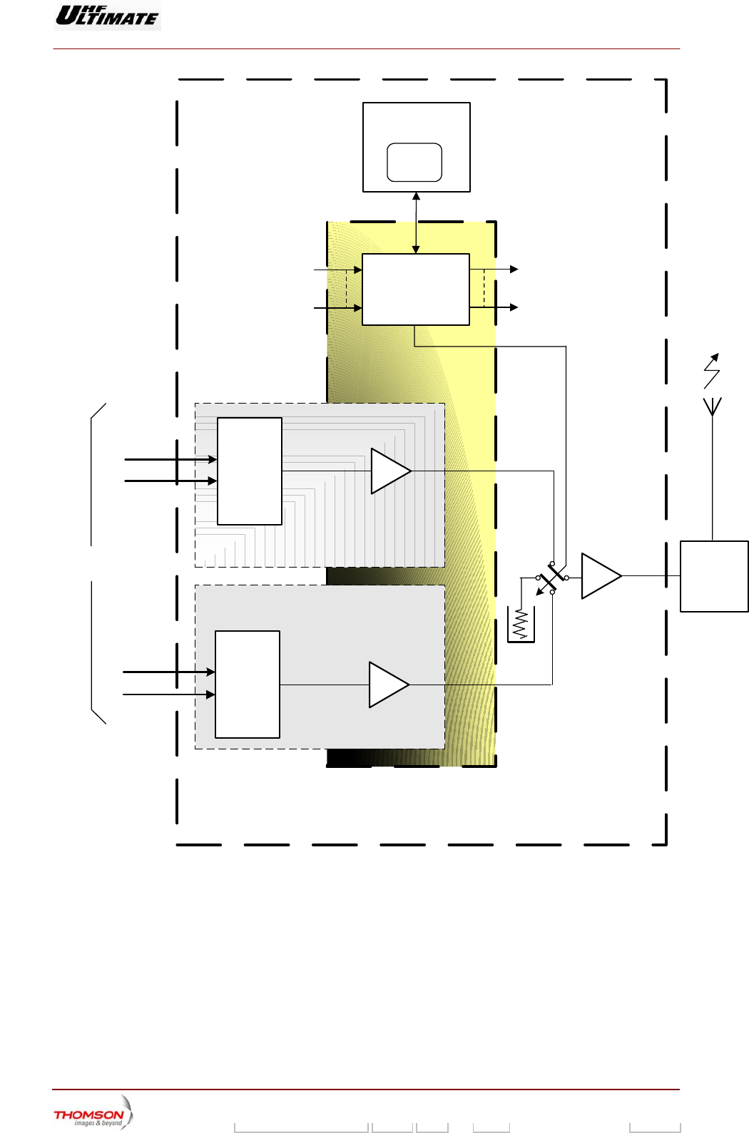
1.2. Simplifier description of transmitter
1.2.1. Basic operation
The MPEG-2 input signals are fed to the exciter inputs, they are converted into digital I and Q
components and are then transposed into RF signals and pre-amplified.
The Dual Drive (DD) version of the transmitter contains two identical exciters, one of which can be
switched to air if the other develops a fault; this on-air switch can be performed automatically or by the
manual intervention of the operator.
The Single Drive (SD) transmitter has only one exciter.
The RF signal from the on-air exciter is fed to a RF amplifier channel.
A central control system monitors the operation of the various units, the operational commands, the
transmitter configuration commands and the data exchange with the user interface.
The BRA/DASI function integrated into each digital exciter provides a fail-safe protection system for
the ASI standard Transport Stream source. This functions provides also for bit rate matching at the
input to the integrated DVB-T or MediaFLO encoder.
Digital Liquid Cooled UHF
TV Equipment
Generale description
9946 V1
45321648.01 104 A E preliminary 10 / 131
Numéro / Number Doc. Rev. Lan
g
u. 16/06/2006 Pa
g
e
Information contained is this document is confidential, is THOMSON property and cannot be disclosed in whatever form without prior written authorization of THOMSON.
RF
signal
RF amplifier
channel
CABINET (S)
(*) Only applies to the DD version
06/112 (e)
Channel 1A
CENTRAL
PROCESSING
UNIT
RF
FILTER
CENTRAL CONTROL
SYSTEM CRATE
50Ω
MPEG input
Channel 2A
Channel 1B
Channel 2B
CONTROL
PANEL
RF
preamplifier A
RF
signal "A"
Adapt.
EXCITER
A
BASIC
TRANSMITTER A
BASIC
TRANSMITTER B
RF
preamplifier B
RF
signal "B"
*
Adapt.
EXCITER
B*
*
*
Figure 1 : Simplified transmitter block diagram
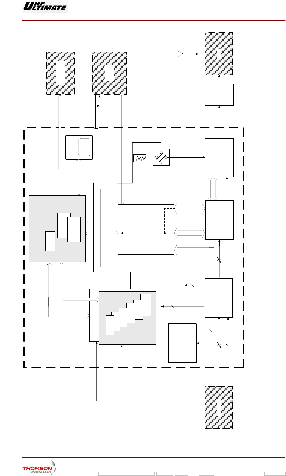
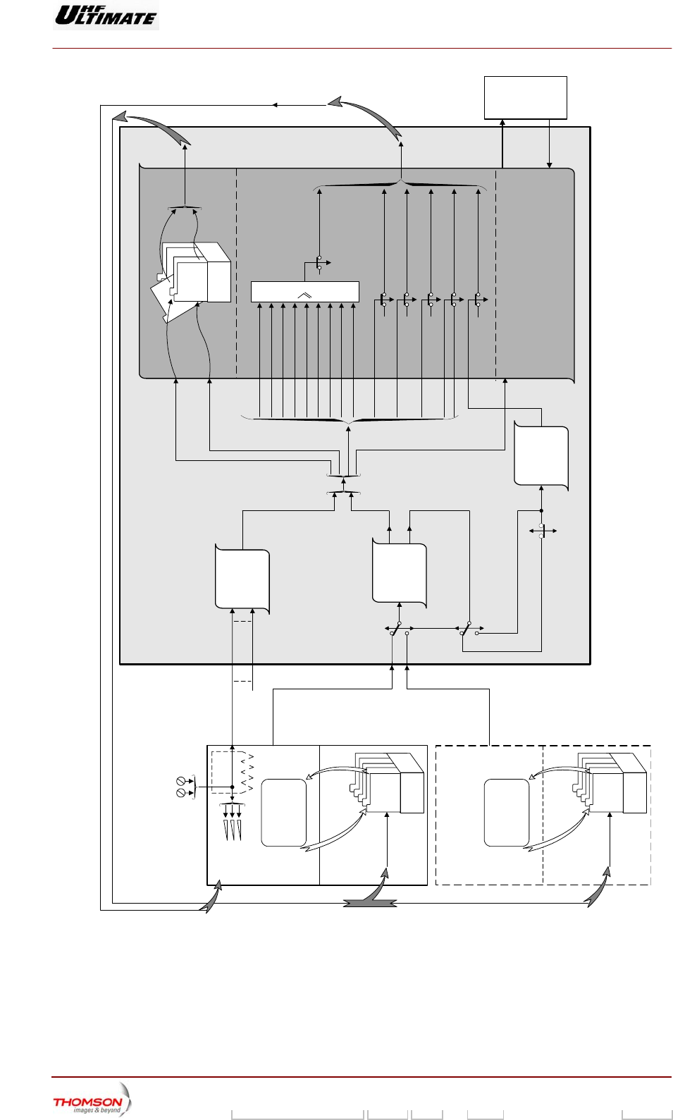
1.2.2. Architecture
The Dual Drive version of the transmitter consists of the following units:
♦ a unit containing two exciters in a redundant switchover system whereby a faulty exciter is replaced
by the other. After digital processing, it transposes the input MPEG signals into a RF output.

Digital Liquid Cooled UHF
TV Equipment
Generale description
9946 V1
45321648.01 104 A E preliminary 11 / 131
Numéro / Number Doc. Rev. Lan
g
u. 16/06/2006 Pa
g
e
Information contained is this document is confidential, is THOMSON property and cannot be disclosed in whatever form without prior written authorization of THOMSON.
Each digital exciter consists of:
• A SIRIUS rack with :
A DVB-T (Europe) modulator board , ATSC (America) modulator board or MédiaFLO modulator
board
a processing signal board,
an RF synthesiser,
a preamplifier,
a Very Low Voltage power supply,
• In the management rack, a RF amplifier (for DVB-T and ATSC modulator only)
♦ a coaxial relay and its 50 Ohms load so that one of the two digital exciters can be switched on RF
amplifier channel.
♦ an RF amplifier way,
♦ a filter unit which filters the RF signal,
♦ a control system as follows:
• A Central Processing Unit (CPU) which supervises the operation of the transmitter electronics
units depending on operator commands and the status conditions in the units.
• the very low voltage power supply for the CPU and the PCL,
• an exciter/CPU interconnection card,
♦ a multiplex card which is the connection unit between the Central Processing Unit and the main
transmitter electronic units,
♦ a Local Control Panel (PCL) which controls the data interchange between the operator and the
transmitter,
♦ a Mains Distribution Panel which provides the mains feeds for the various transmitter power
supplies,
♦ the power supplies for the RF amplifiers,
♦ the cooling system for the Exciter/CPU system.
The following associated external sub-systems for the SD/DD transmitters combine together to form a
complete transmission operation:
♦ an external cooling system to cool the transmitter,
♦ an input three-phase mains supply,
♦ an external changeover system so that the transmitter can be switched between a dummy load and
the antenna,
♦ A remote user interface (optional) with facilities for remote control of the transmitter.
Simple Drive transmitter
The Single Drive version is physically different from the Double Drive version in that it only has one
digital exciter .
Digital Liquid Cooled UHF
TV Equipment
Generale description
9946 V1
45321648.01 104 A E preliminary 12 / 131
Numéro / Number Doc. Rev. Lan
g
u. 16/06/2006 Pa
g
e
Information contained is this document is confidential, is THOMSON property and cannot be disclosed in whatever form without prior written authorization of THOMSON.
EXCITER B (SIRIUS)
EXCITER A (SIRIUS)
RF PREAMPLIFIER
GPS RECEIVER
Very low voltage
POWER
SUPPLY
SYNTHESIZER
TS BOARD
DIGITAL BOARD
(MODULATOR)
CABINET(S)
LOCAL
CONTROL
PANEL
AMPLIFIER
POWER SUPPLY
Data interface
COOLING
SYSTEM
Air cooled
or water cooled
MULTIPLEX
CARD(S)
RF
signal
A or B
Power supplies
Status
Command
Status
signals
To
Control System
PSU
Mains
MEPG input A
Output
RF signal
06/113 (e)
RF signal (B)
RF signal (A)
RF AMPLIFIERS BAND
FILTER
FAN UNIT
FOR THE CENTRAL
CONTROL SYSTEM
LOAD
REMOTE USER
INTERFACE
Mains Input MAINS DISTRIBUTION
PANEL
Status signals
Command signals
Status signals
Command signals
DC voltage
50Ω
load
COAXIAL
RELAY
MEPG input B
*
*OPTIONS
EXCITER/CPU INTERCONNECTION
OF CONTROL SYSTEM CRATE
(B)
(A)
Status signals
Command signals
Status signals
Command signals
CENTRAL
PROCESSING
UNIT
VERY LOW VOLTAGE
POWER SUPPLY (2)
VERY LOW VOLTAGE
POWER SUPPLY (1)
Emergency
Mains Input
Figure 2 : Transmitter (Double drive) structure

Digital Liquid Cooled UHF
TV Equipment
Detailed operational description
9946 V1
45321648.01 104 A E preliminary 13 / 131
Numéro / Number Doc. Rev. Lan
g
u. 16/06/2006 Pa
g
e
Information contained is this document is confidential, is THOMSON property and cannot be disclosed in whatever form without prior written authorization of THOMSON.
2. Detailed operational description
2.1. Introduction
The main transmitter functions are as follows:
♦ transmission,
♦ control,
♦ mains distribution,
♦ Cooling.
Two individual sections have been devoted to the last two functions.

Digital Liquid Cooled UHF
TV Equipment
Detailed operational description
9946 V1
45321648.01 104 A E preliminary 14 / 131
Numéro / Number Doc. Rev. Lan
g
u. 16/06/2006 Pa
g
e
Information contained is this document is confidential, is THOMSON property and cannot be disclosed in whatever form without prior written authorization of THOMSON.
2.2. Transmission function
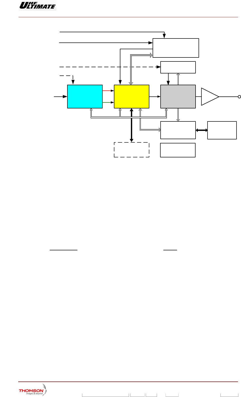
2.2.1. Operational description of digital exciter
The exciter (EMB) transposes the input base-band MPEG signal into an RF signal using a local
frequency oscillator from a synthesiser.
The incoming data stream signal (MPEG2-TS) is processed by the Channel Modulator (TS card),
depending on the standard (DVB-T or ATSC), which provides an output complex digital signal in the
form of two parallel I and Q digital signals and a clock reference.
These I & Q signals are then processed by the DAP (Digital adaptative pre-correction):
♦ Optional Clipping,
♦ Optional Adaptive Linear Equalisation (ALE),
♦ Adaptive non-linear correction.
With the digital filter option, as long as the magnitude of the vector is less than a given threshold, the
vector remains unchanged. For magnitudes higher than the threshold, the vector is replaced by the
specific complex value of the threshold. The process does not influence the phase.
The linearity correction ALE, as well as the non linearity correction (LUT) are based on the following
process: comparing the demodulated I & Q output signals with the I & Q input signals, computing the
transfer curve, inverting this transfer curve, loading new coefficients from LUT (for non linearity signal
correction) and for ALE (linearity signal correction). The DAP output provides two parallel pre-
corrected I & Q digital signals.
In the TX card, these digital signals are then converted into the analogue domain and directly
transposed on a low-level RF signal. This unit also receives a sample of the output RF signal, which is
demodulated and split into two components, I & Q. These complex components are then digitised and
forwarded to DAP where they are compared with the input complex components. The TX card
performs an Automatic Level Control thanks to a detected envelope voltage from the power amplifier
channel of the transmitter.
Digital Liquid Cooled UHF
TV Equipment
Detailed operational description
9946 V1
45321648.01 104 A E preliminary 15 / 131
Numéro / Number Doc. Rev. Lan
g
u. 16/06/2006 Pa
g
e
Information contained is this document is confidential, is THOMSON property and cannot be disclosed in whatever form without prior written authorization of THOMSON.
I / Q
Q
I
Pre-
amplifier
DIGITAL
MPEG - TS
RF Feedback
(from TX output)
06/114(e)
External inputs
10 MHz
1 pps
Synthesizer
Signal
Processing
COFDM
or 8VSB
or MediaFLO
Modulator
RF Output
COFDM only
PSU
+5V +24V
Local external
terminal (VT)
CPU
or
Board Interface
To Control and
Monitoring
System
Feedback
ALE Switch
Wide band
Down/conversion
RS232
Complex
Up/Converter
IF
RF Feedback
(from RF filter output)
A Preamplifier allows a peak output power of + 40 dBm.
An internal RF Synthesizer, with different options, feeds the TX card for the RF up and down
conversions.
The Internal Control and Monitoring is achieved by a serial link, SPI bus, managed by the principal
digital card. In this way It is the Communication Interface node between all the digital cards of the
SIRIUS. The principal digital card is also the SIRIUS interface with the external environment:
Transmitter C/M or external terminal (VT, PC...). This external communication is achieved using RS
232 interfaces: (Ethernet or CAN Bus in factory) one for the transmitter interface, one for a external
terminal which can be plugged directly in the front face of the DAP unit.
Use of a redundant transport stream is ensured by the optional «BRA/DASI» function designed to
select one of 2 ASI inputs. It also integrates a Bit Rate Adapter (BRA) designed to adapt the bit rate
fed to the modulator, by means of the synchronisation clock called «Synchro IN».
2.2.2. Exciter change-over
In the Double Drive version, coaxial relay routes the RF signal from the exciter selected by the control
system to the amplifier channels. This switcher is controlled by the "command control system" in the
Central Processing Unit, which also takes into account both the operator commands and any fault
signals sent from the selected exciter.
2.2.3. ASI input change-over
The switching of the way 1 towards the way 2 and conversely is always possible whatever is the state
of the stream ASI on 2 ways. The switching of a way on the other one is left with the choice of the
digital processor of the card (modulator). The processor has to ask about alarms of the other way
before commuting. The switching seamless is not guaranteed.
Digital Liquid Cooled UHF
TV Equipment
Detailed operational description
9946 V1
45321648.01 104 A E preliminary 16 / 131
Numéro / Number Doc. Rev. Lan
g
u. 16/06/2006 Pa
g
e
Information contained is this document is confidential, is THOMSON property and cannot be disclosed in whatever form without prior written authorization of THOMSON.
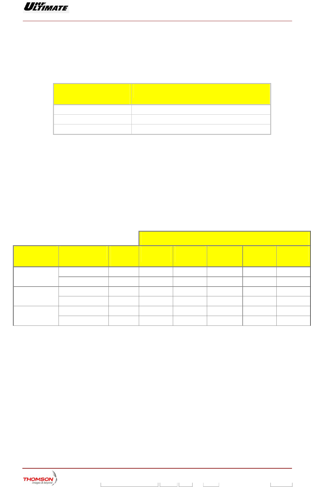
2.2.4. Amplification of the RF signal
The output RF signals from the exciters are low power signals. This signal is sent to the inputs of the
amplifiers, which are mounted in trays and are all connected in parallel.
The following shows the number of amplifier modules as a function of the transmitter power.
RMS POWER
(BEFORE FILTER) NUMBER OF RF AMPLIFIERS
3,1 kW 6 amplifiers
5,2 kW 10 amplifiers
6,3 kW 12 amplifiers
Each RF output from the amplifier modules is fed to a type F.I.C.S. (Full Isolated Coupling System)
combiner which guarantees a mutual isolation of the order of 26 dB. This coupling system allows an
on-air amplifier module to be removed without shutting down the transmission. Thus a faulty output
amplifier can be replaced by a spare amplifier.
The amplifier modules are powered by 10 kW plug-in power supplies with very high reliability, which
provide 250 A at 28 V (voltage programmable on 3 bits from 24 to 31 V), (one power supply for two
amplifiers).
The use of several power supplies and amplifiers in the RF amplifier channel leads to a minimum
degradation of power performance parameters when any of these units become faulty.
EXAMPLE FOR DVB-T TRANSMITTER NUMBER OF FAULTY UNITS
TRANSMITTER
POWER
UNIT TOTAL
NUMBER 1 2 3 4 5
Amplifier 8 -1.16 dB -2.5 dB -4.08 dB -6 dB -8.52 dB 3.2kW
Power supply 4 -2.5 dB -6 dB -12 dB
Amplifier 12 -0.76 dB -1.6 dB -2.5 dB -3.5 dB -4.7 dB 5kW
Power supply 6 -1.6 dB -3.5 dB -6 dB -9.5 dB -15.5 dB
Amplifier 16 -0.64 dB -1.16 dB -1.8 dB -2.5 dB -3.25 dB 6.5kW
Power supply 8 -1.16 dB -2.5 dB -4.08 dB -6 dB -8.52 dB
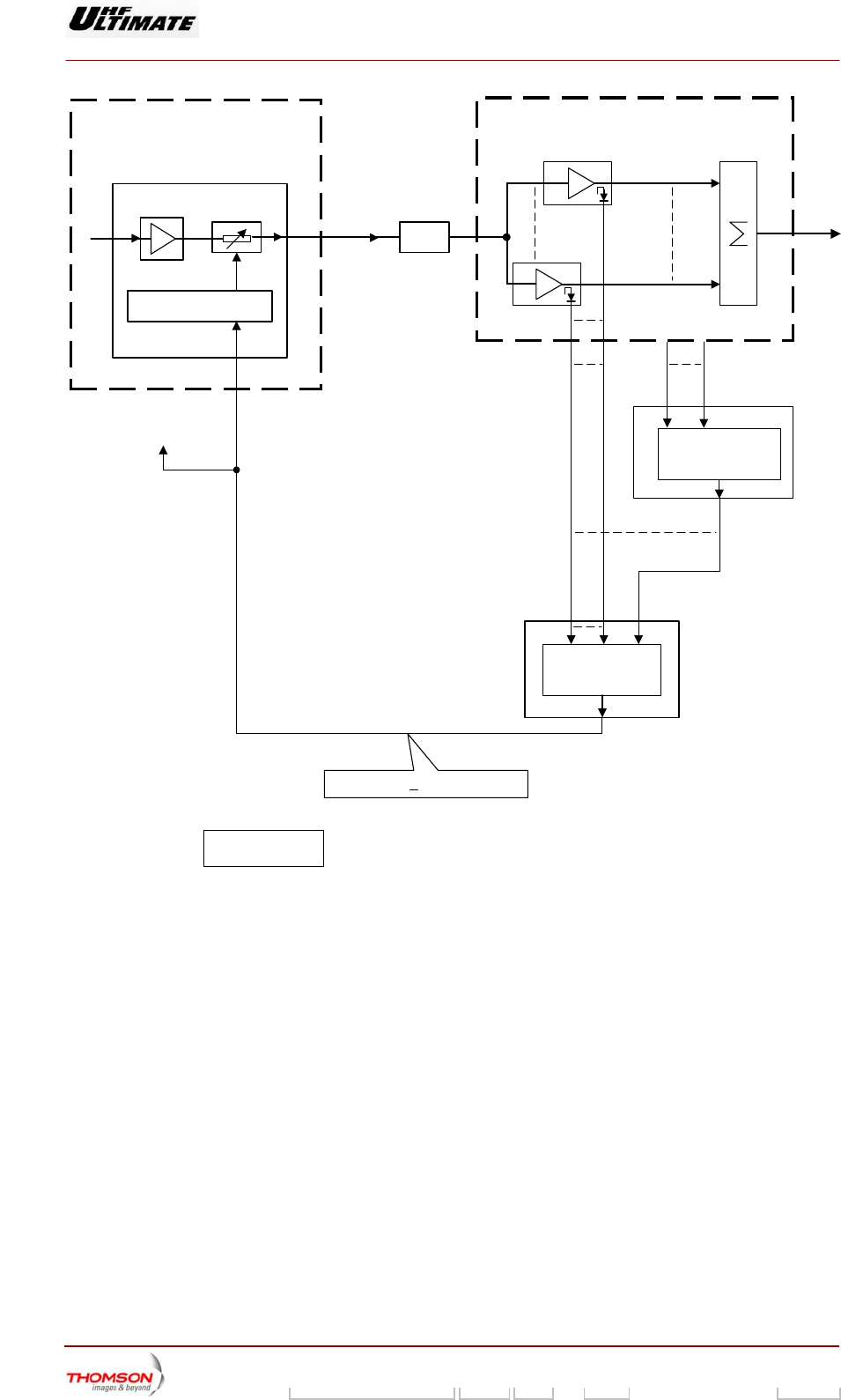
AGC acting on the power level compensates for loss of gain in the amplifiers.
An Automatic Gain Control (AGC) loop is used to regulate the power output. Each amplifier provides
an AGC voltage (detected voltage) which is fed to an analogue "OR" gate on the transmitter multiplex
board. These data are sent to the TX board of the exciter, on which there is an RF gain control in the
form of an attenuator which controls the output power.
The "OR" gate ensures that the exciter output power signal is controlled by the largest of the AGC
voltages from the amplifiers. Consequently the RF power amplifier which is delivering the largest
power level is taken as the reference for the AGC loop. This means that all amplifiers are equally
driven irrespective of failures in one or more of them; this also ensures a constant linearity for the
amplifier channel.
Digital Liquid Cooled UHF
TV Equipment
Detailed operational description
9946 V1
45321648.01 104 A E preliminary 17 / 131
Numéro / Number Doc. Rev. Lan
g
u. 16/06/2006 Pa
g
e
Information contained is this document is confidential, is THOMSON property and cannot be disclosed in whatever form without prior written authorization of THOMSON.
RF AMPLIFICATION
AMPLIFIER
EXCITER
TX Board
Amplifier voltage 1
Parallel connection of
amplifier voltages
MULTIPLEX
CARD N°1
OTHER
MULTIPLEX
CARD
Amplifier voltage N
AGC voltage
* To 2nd
exciter
AGC voltage > Amplifier voltage
* : On Dual Drive
transmitter
98/232c (e)
Parallel connection of
amplifier voltages
RF
AMPLIFIER ATTENUATOR
GAIN CONTROL
AGC voltage
RF signal ATT.
Figure 3 : AGC operational block diagram

Digital Liquid Cooled UHF
TV Equipment
Detailed operational description
9946 V1
45321648.01 104 A E preliminary 18 / 131
Numéro / Number Doc. Rev. Lan
g
u. 16/06/2006 Pa
g
e
Information contained is this document is confidential, is THOMSON property and cannot be disclosed in whatever form without prior written authorization of THOMSON.
2.3. Description of the overall transmitter control system
2.3.1. Introduction
The overall control system for the various transmitter units is supervised by the Central Processing
Unit (CPU). This control system takes the following into account:
♦ polling of the events data from the various transmitter units,
♦ polling of the operator commands,
♦ command control system,
♦ Elaboration of the global quality note
♦ processing of faults,
♦ data transfer between exciter and CPU.
♦ user interface data from:
• display control system,
• the logbook control system.
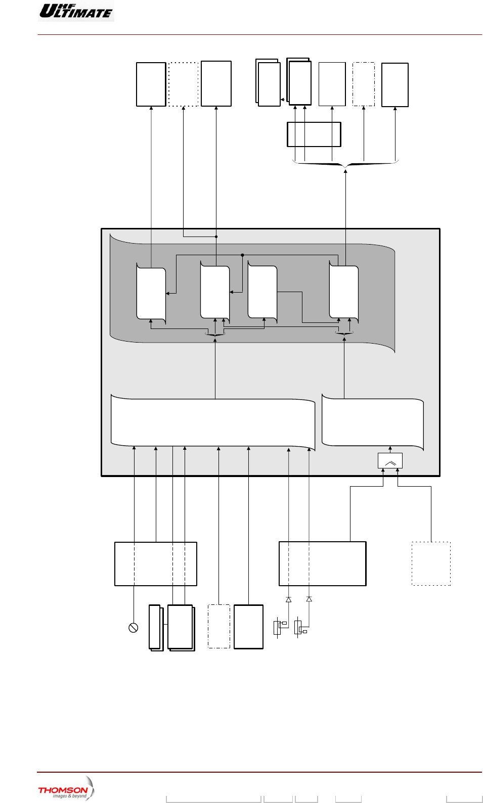
2.3.2. Polling of events data
This processing unit continuously polls the transmitted signal parameter characteristics and the status
condition data from the main transmitter units as follows:
♦ RF amplifiers,
♦ Amplifier power supplies,
♦ synthesiser,
♦ exciter(s)
♦ Multiplex card.
In addition, sensors or probes detect and transmit data on the following:
♦ liquid parameter values and associated cooling system,
♦ Mains input supply system,
♦ RF output signal (forward wave and return wave).
Every new event is detected and associated data are sent to the following systems:
♦ processing of faults,
♦ display control system,
♦ Log book control system.
Digital Liquid Cooled UHF
TV Equipment
Detailed operational description
9946 V1
45321648.01 104 A E preliminary 19 / 131
Numéro / Number Doc. Rev. Lan
g
u. 16/06/2006 Pa
g
e
Information contained is this document is confidential, is THOMSON property and cannot be disclosed in whatever form without prior written authorization of THOMSON.
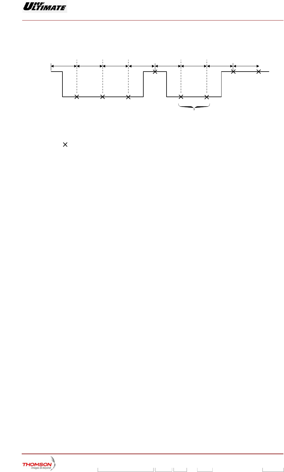
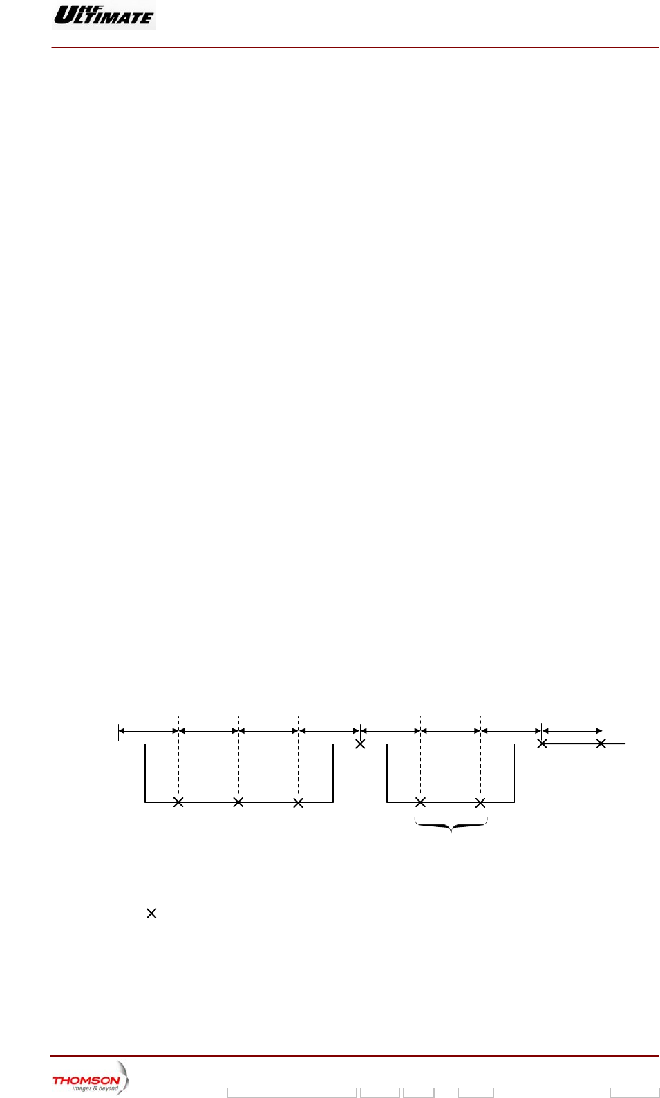
Delays and time lags in equipment
The back-up functions are totally hardware based; the CPU board stores data according to the type of
event and provides a fault display system.
(1) (1) (1) (1) (1) (1) (1) (1)
CPU ignores faults
No fault
Faulty parameter
Fault appears
Fault confirmed by
CPU for storage
and display
(1) : Parameter polling period (approx. 300 ms)
: Parameter polling by CPU
The CPU confirms a parameter fault in the transmitter (not in the exciter) after it has been detected
during three successive polling periods.
Three to four seconds after its appearance a fault will be displayed and stored in the logbook.
After a start command from the CPU a delay of 20 seconds (CPU software) is applied to the detection
of transmitter RF faults.
After a start command from the CPU a delay of 5 seconds (multiplex board hardware) is applied to the
detection of faults relating to cooling air/water pressure and flow rate.
Digital Liquid Cooled UHF
TV Equipment
Detailed operational description
9946 V1
45321648.01 104 A E preliminary 20 / 131
Numéro / Number Doc. Rev. Lan
g
u. 16/06/2006 Pa
g
e
Information contained is this document is confidential, is THOMSON property and cannot be disclosed in whatever form without prior written authorization of THOMSON.
UNITE CENTRALE
CENTRAL PROCESSING UNIT
Carte de
brassage
Multiplex card
IHM
DISTANT
REMOTE USER
INTERFACE
PC Local
Local control
panel
Sondes RF/RF probes
EMB
EXCITER
AMPLIFICATEUR
AMPLIFIER
Capteurs
Sensors
Carte de brassage
Multiplex card
SCRUTATION
DES
COMMANDES
OPERATEURS
POLLING OF
OPERATOR
COMMANDS
SCRUTATION
DES
EVENEMENTS
POLLING OF
EVENTS DATA
GESTION UNITE CENTRALE
OVERALL TRANSMITTER
CONTROL SYSTEM
SYNTHÉTISEUR
SYNTHESIZER
EMB
EXCITER
1
SYNTHÉTISEUR
SYNTHESIZER
98/234b (f-e)
ALIMENTATION DE
PUISSANCE
AMPLIFIER POWER
SUPPLY
Etat Capteurs
Sensor status signals
Etat carte de brassage
Multiplex card status signals
Etat amplificateur
Amplifier status signals
Etat alimentation de puissance
Amplifier power supply status
signals
Etat synthétiseur
Synthesizer status signals
Etat EMB
Exciter status signals
Etat signal sortie émetteur
Transmitter output status signals
Commandes opérateurs
Operator commands
Commandes opérateurs
Operator commands
Commandes manuelles
Manual commands
Gestion des
Commandes
Command control
system
Analyse et
Traitement
des défauts
Fault analysis and
processing system
Gestion des
affichages
Display control
system
Evénements
Events
Gestion du
Journal de Bord
Log book control
system
Information journal de bord
Log book data
Information état émetteur
Transmitter status data
Information état émetteur
Transmitter status data
Terminal Journal
de Bord
Log book terminal
IHM
Distant
Remote user
interface
PC
Local
Local control
panel
Amplification
Amplification
Alimentation
de puissance
Amplifier power
supply
Commandes
Command data
SYSTEME de
REFROIDISSEMENT
COOLING SYSTEM
Etat signal onde retour sortie
émetteur
Transmitter SWR output status
signal
Figure 4 – Block diagram of the control system and events signals
Digital Liquid Cooled UHF
TV Equipment
Detailed operational description
9946 V1
45321648.01 104 A E preliminary 21 / 131
Numéro / Number Doc. Rev. Lan
g
u. 16/06/2006 Pa
g
e
Information contained is this document is confidential, is THOMSON property and cannot be disclosed in whatever form without prior written authorization of THOMSON.
2.3.3. Polling of operator commands
The Central Processing Unit (CPU) receives the operator commands sent from the Local Control
Panel (PCL) or a remote user interface. These commands are taken into account by the following
systems:
♦ PCL windows and indicator lamp control system,
♦ Command control system.
2.3.4. Command control sytem
This processing unit continuously polls the transmitted signal parameter characteristics and the status
condition data from the main transmitter units as follows:
♦ RF amplifiers,
♦ Amplifier power supplies,
♦ synthesiser,
♦ exciter(s)
♦ Multiplex card.
In addition, sensors or probes detect and transmit data on the following:
♦ liquid parameter values and associated cooling system,
♦ Mains input supply system,
♦ RF output signal (forward wave and return wave).
Every new event is detected and associated data are sent to the following systems:
♦ processing of faults,
♦ display control system,
♦ Log book control system.
Delays and time lags in equipment
The back-up functions are totally hardware based; the CPU board stores data according to the type of
event and provides a fault display system.
(1) (1) (1) (1) (1) (1) (1) (1)
CPU ignores faults
No fault
Faulty parameter
Fault appears
Fault confirmed by
CPU for storage
and display
(1) : Parameter polling period (approx. 300 ms)
: Parameter polling by CPU
The CPU confirms a parameter fault in the transmitter (not in the exciter) after it has been detected
during three successive polling periods.
Three to four seconds after its appearance a fault will be displayed and stored in the logbook.

Digital Liquid Cooled UHF
TV Equipment
Detailed operational description
9946 V1
45321648.01 104 A E preliminary 22 / 131
Numéro / Number Doc. Rev. Lan
g
u. 16/06/2006 Pa
g
e
Information contained is this document is confidential, is THOMSON property and cannot be disclosed in whatever form without prior written authorization of THOMSON.
After a start command from the CPU a delay of 20 seconds (CPU software) is applied to the detection
of transmitter RF faults.
After a start command from the CPU a delay of 5 seconds (multiplex board hardware) is applied to the
detection of faults relating to cooling air/water pressure and flow rate.
Digital Liquid Cooled UHF
TV Equipment
Detailed operational description
9946 V1
45321648.01 104 A E preliminary 23 / 131
Numéro / Number Doc. Rev. Lan
g
u. 16/06/2006 Pa
g
e
Information contained is this document is confidential, is THOMSON property and cannot be disclosed in whatever form without prior written authorization of THOMSON.
UNITE CENTRALE
CENTRAL PROCESSING UNIT
Carte de
brassage
Multiplex card
IHM
DISTANT
REMOTE USER
INTERFACE
PC Local
Local control
panel
Sondes RF/RF probes
EMB
EXCITER
AMPLIFICATEUR
AMPLIFIER
Capteurs
Sensors
Carte de brassage
Multiplex card
SCRUTATION
DES
COMMANDES
OPERATEURS
POLLING OF
OPERATOR
COMMANDS
SCRUTATION
DES
EVENEMENTS
POLLING OF
EVENTS DATA
GESTION UNITE CENTRALE
OVERALL TRANSMITTER
CONTROL SYSTEM
SYNTHÉTISEUR
SYNTHESIZER
EMB
EXCITER
1
SYNTHÉTISEUR
SYNTHESIZER
98/234b (f-e)
ALIMENTATION DE
PUISSANCE
AMPLIFIER POWER
SUPPLY
Etat Capteurs
Sensor status signals
Etat carte de brassage
Multiplex card status signals
Etat amplificateur
Amplifier status signals
Etat alimentation de puissance
Amplifier power supply status
signals
Etat synthétiseur
Synthesizer status signals
Etat EMB
Exciter status signals
Etat signal sortie émetteur
Transmitter output status signals
Commandes opérateurs
Operator commands
Commandes opérateurs
Operator commands
Commandes manuelles
Manual commands
Gestion des
Commandes
Command control
system
Analyse et
Traitement
des défauts
Fault analysis and
processing system
Gestion des
affichages
Display control
system
Evénements
Events
Gestion du
Journal de Bord
Log book control
system
Information journal de bord
Log book data
Information état émetteur
Transmitter status data
Information état émetteur
Transmitter status data
Terminal Journal
de Bord
Log book terminal
IHM
Distant
Remote user
interface
PC
Local
Local control
panel
Amplification
Amplification
Alimentation
de puissance
Amplifier power
supply
Commandes
Command data
SYSTEME de
REFROIDISSEMENT
COOLING SYSTEM
Etat signal onde retour sortie
émetteur
Transmitter SWR output status
signal
Figure 5 – Block diagram of the control system and events signals

Digital Liquid Cooled UHF
TV Equipment
Detailed operational description
9946 V1
45321648.01 104 A E preliminary 24 / 131
Numéro / Number Doc. Rev. Lan
g
u. 16/06/2006 Pa
g
e
Information contained is this document is confidential, is THOMSON property and cannot be disclosed in whatever form without prior written authorization of THOMSON.
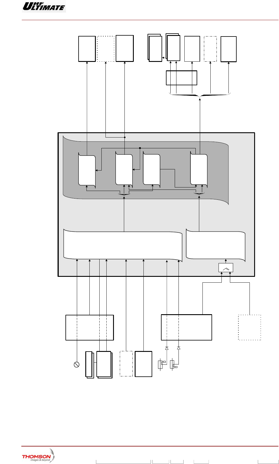
2.3.5. Processing of faults
2.3.5.1. Outline
Faults are detected by sensors (liquid flow/air pressure, temperature and reflectometer probes) and
surveillance devices inside the units (power supplies, SWR protection, ...).
Fault signals from these sensors are picked up:
♦ either by a loop protection system in the multiplex card,
♦ or by the fault processing system in the Central Processing Unit.
All faults without exception are also picked up by the following systems in the CPU:
♦ log book control system,
♦ display control system.
2.3.5.2. Fault analysis system
All fault signals received by the Central Processing Unit are analysed before being processed. This
analysis consists in checking that some other event is not responsible for the fault signal; some events
(transient phase anomalies, fault in multiplex card, amplifiers missing, ...) can cause anomalies on
other units.
Example: When a multiplex card fault appears, the status data, which should pass through the
card, will not be picked up by the system. When this happens some faults will not be
processed.
Notes: Although to a certain extent the various units are protected by the system the following
units have their own automatic protection systems:
♦ amplifier power supply,
♦ amplifiers,
♦ exciter system.
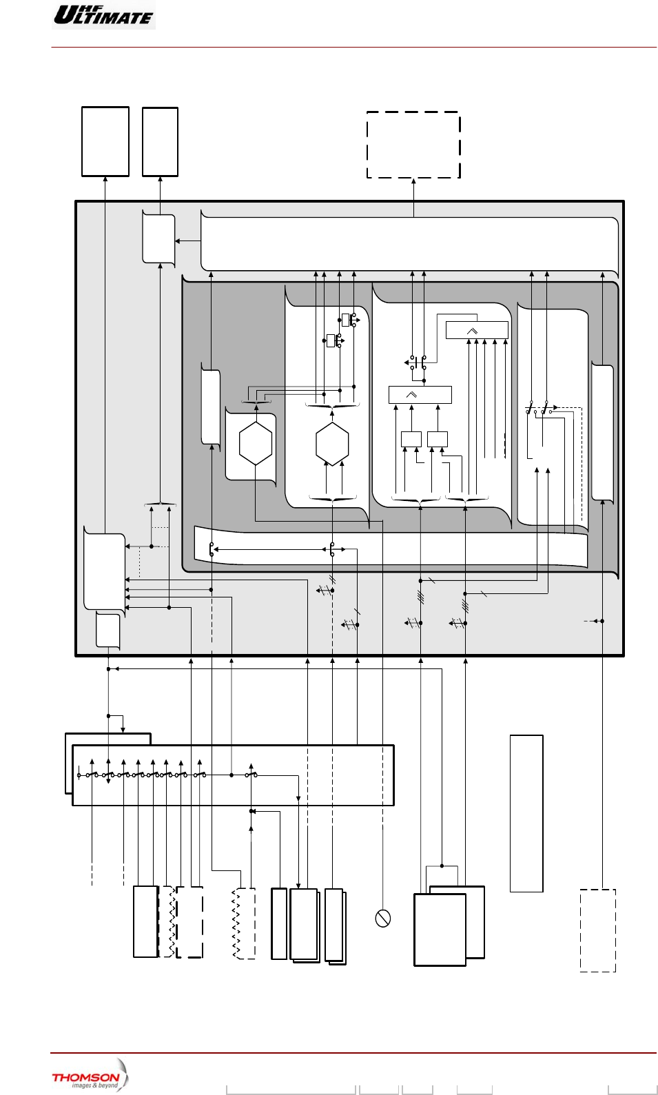
2.3.5.3. Fault processing facilities
The fault processing system generates commands, which protect the transmitter operation from the
fault signals, which occur. It reacts to the following events:
♦ air pressure/input liquid temperature fault,
♦ SWR/amplifier overdrive fault,
♦ SWR antenna fault,
♦ Automatic exciter changeover (only applies to the dual drive version),
♦ Automatic transmitter on-air/off-air switch,
♦ Re-setting of synthesiser.
Digital Liquid Cooled UHF
TV Equipment
Detailed operational description
9946 V1
45321648.01 104 A E preliminary 25 / 131
Numéro / Number Doc. Rev. Lan
g
u. 16/06/2006 Pa
g
e
Information contained is this document is confidential, is THOMSON property and cannot be disclosed in whatever form without prior written authorization of THOMSON.
* AMPLIFIERS
<
* : These transmitter units are self-protected
(1) : Multiplex card N°1 only
(2) : Only on multiplex card N°1
* AMPLIFIER
POWER
SUPPLY
Power supply on/off
Input liquid temperature
Amplifier power supply
status signals
Power amplifier
status signals
Multiplex card status
signals
Command
control
system
DISPLAY
CONTROL
SYSTEM
LOG BOOK
CONTROL
SYSTEM
CENTRAL PROCESSING
UNIT
FAULT PROCESSING
COMMAND
CONTROL
SYSTEM
(see previous
figure)
TRANSMITTER
UNITS
LOG BOOK
TERMINAL
LOCAL
CONTROL
PANEL OR
REMOTE USER
INTERFACE
Multiplex
card fault
FILTER UNIT COOLING
SYSTEM Pressure fault
Status data from selected exciter
On-air/off-air override
Status data from reserve exciter
*
EXCITER(s)
Return wave
Probes RF
SWR/AMPLIFIER
OVERDRIVE FAULT
SWR fault
Overdrive
fault
Reset faulty amplifier
Number
of faulty
amplifiers
> N1
- 3dB
command
- 6dB
command T
Transmitter off-air
T
FAULT
ANALYSIS
05/009 (e)
AUTOMATIC ON-AIR/OFF-AIR SWITCH
Transmitter On-air switch
B MPEG missing
A MPEG missing
Transmitter Off-air switch
Yes
No
Exciter MPEG present on antenna
Exciter MPEG missing on antenna
SYNTHESIZER Synthesizer unlocked
Automatic changeover aiready
performed
SYNTHESIZER RE-SETTING Synthesizer frequency
re-setting
&
Input liquid temperature Input liquid
temperature fault
- 6dB command
SWR ≥2
antenna
MAINS
DISTRIBUTION
PANEL
EXTERNAL COOLING
SYSTEM
Output liquid temperature (2)
(2)
(2)
(2)
(1)
Station protection system
Cabinet protection system
MULTIPLEX CARD(S)
Command
On-air/off-air
override
from
exciter(s)
On-air Off-air
INTERNAL COOLING SYSTEM
INTERNAL COOLING
SYSTEM
Loss of mains phases
Mains isolator open
(2)
PUMP fault
Liquid flow alarm
(2)
Loop protection system
(2)
Liquid flow fault
Cooling power
supply missing
RW signal
SWR antenna
fault
SWR ANTENNA
FAULT
- 3dB
- 6dB
Tx off -air
Input signal
fault MPEG
MPEG Abs.
Pilot Abs.
On Exciter
1
1
Pilot fault
10MHz-1PPS
Exciter
pilot
fault
Input
signal
fault
Change over manual
Maintenance mode
&
&
AUTOMATIC EXCITER CHANGE OVER
Exciter fault
Exciter fault
Automatic changeover aiready
performed
Figure 6 : Fault processing

Digital Liquid Cooled UHF
TV Equipment
Detailed operational description
9946 V1
45321648.01 104 A E preliminary 26 / 131
Numéro / Number Doc. Rev. Lan
g
u. 16/06/2006 Pa
g
e
Information contained is this document is confidential, is THOMSON property and cannot be disclosed in whatever form without prior written authorization of THOMSON.
Input liquid temperature fault
An "input liquid temperature" fault signal from the sensor in the internal cooling system sends a
command to lower the transmitter power by 6 dB.
SWR or amplifier overdrive fault
When the number of faulty amplifiers (SWR or overdrive fault) in the amplifier channel is greater than a
particular number (which depends on the total number of amplifiers), the fault processing system
triggers the following sequence of operations:
♦ re-initialisation of the faulty amplifiers,
♦ if the fault persists:
• reduction of transmitter power by 3 dB,
• re-initialisation of faulty amplifiers.
♦ if the fault persists:
• reduction of transmitter power by 6 dB,
• re-initialisation of faulty amplifiers,
♦ if the fault persists: shutdown of transmitter
SWR antenna fault
When the return wave antenna is higher or equal at 2, the fault processing system triggers the
following sequence of operations:
♦ reduction of transmitter power by 3dB.
♦ if the fault persists: reduction of transmitter power by 6 dB
♦ if the fault persists: shutdown of transmitter.
Automatic exciter changeover (only applies to the dual drive version)
The fault processing system sends a changeover to reserve exciter command signal to the command
control system when one of the following fault signals is received and when the reserve exciter is
switched off and fault-free:
♦ Exciter fault :
• Communication link failure with the Sirius,
• Power supply of exciter fault,
• RF output signal missing from Sirius (Sirius rack is ON with an modulator not mute).
• Modulator fault,
• Sirius fault,
• RF preamplifier fault,
• Signal missing of the 10 MHz external (external GPS configuration only),
• Board fault (synthetizer or TS board or Tx board or GPS board (internal GPS configuration only)
or EXT INPUT board (if installed card).
♦ Pilot fault :
• Signal missing of the 10 MHz external when the synthesizer 10 MHz is configured in external.
• 1 PPS signal missing when MUTE function is selected for this signal (in mode SFN only).
♦ Absence or input MPEG-2 signal faulty when the modulator is not configured in PRBS (this
configuration is not possible in SFN mode).

Digital Liquid Cooled UHF
TV Equipment
Detailed operational description
9946 V1
45321648.01 104 A E preliminary 27 / 131
Numéro / Number Doc. Rev. Lan
g
u. 16/06/2006 Pa
g
e
Information contained is this document is confidential, is THOMSON property and cannot be disclosed in whatever form without prior written authorization of THOMSON.
However this changeover command is not confirmed if the Reserve exciter is currently on-air or one of
the following faults signals is received from the Reserve exciter:
♦ reserve exciter fault,
♦ no MPEG-2 signal at input.
Automatic transmitter on-air/off-air switch (auto start)
As soon as the fault processing system detects that there is neither an MPEG-2 signal at the input of
the on-air exciter nor at the input of the reserve exciter it automatically switches the transmitter off-air.
As soon as the fault processing system detects that there is an MPEG-2 signal at the input of the on-
air exciter or/and at the input of the reserve exciter it automatically switches the transmitter to air.
If an automatic changeover has taken place and the transmitter has not been re-initialised, the system
only takes note of whether or not there is a signal at the input of the exciter connected to the antenna.
Re-setting of synthesiser
If it is detected that the synthesiser is unlocked the "fault processing system" sends a command for its
re-setting which includes the frequency value.
Notes: When a multiplex card fault appears, the status data, which should pass through the
card, will not be picked up by the system. When this happens some faults will not be
processed.
Although to a certain extent the various units are protected by the system the following
units have their own automatic protection systems:
♦ amplifier power supply,
♦ amplifiers,
♦ exciter system.
2.3.5.4. Protection system
There are some surveillance devices which force the transmitter to be shut down when they detect
faults. All the surveillance devices are connected together in a continuous loop system. As soon as a
fault appears, the loop protection system forces a transmitter off-air switch by switching off the
amplifier power supplies.
The protection system remains in operation when the Central Processing Unit is not in circuit. Thus the
transmitter is protected even when the control system is faulty.
The following are the elements of the loop protection system :
♦ station protection system,
♦ cabinet protection system,
♦ data on the status condition of the mains isolator in the mains distribution panel,
♦ status data on the mains input system (phase inversion and unbalanced phase conditions),
♦ surveillance device which monitors the temperature of the output liquid from the internal cabinet
cooling system,
♦ surveillance device which monitors the cooling system motor and the presence of mains on the
motor,
♦ surveillance device which monitors the liquid flow from the internal cabinet.
The protection system is switched on or off by the on/off command from the Central Processing Unit or
by the on-air/off-air overrides command from the On-Air exciter if the Central Processing Unit is not
operational.
Digital Liquid Cooled UHF
TV Equipment
Detailed operational description
9946 V1
45321648.01 104 A E preliminary 28 / 131
Numéro / Number Doc. Rev. Lan
g
u. 16/06/2006 Pa
g
e
Information contained is this document is confidential, is THOMSON property and cannot be disclosed in whatever form without prior written authorization of THOMSON.
In a transmitter configuration containing several cabinets, each cabinet has its own protection system
controlled by the multiplex card. The two loop protection systems are connected together so that open
circuiting the first either one will cause the shutdown of the cabinet. The protection systems are
identical on both cards with the exception of the station protection.
In the case of a 3.75 or 5 kW transmitter in which the second multiplex card is in the same cabinet, the
loop protection system on the second card does not accept the surveillance signals; it is simulated by
a hardwired closed loop.
2.3.6. Computing the overall quality assessment of the RF signal
The quality of the RF output signal of a digital transmitter is assessed by a number between 1 and 20,
called overall quality assessment (QN).
This overall quality assessment is indicated in a window of the PCL and also on the remote control
position.
This assessment is processed by the transmitter CPU and a "fault" signal is sent on a hard wired
connection. This fault loop, along with the overall quality assessment, is used in PR or N+1 transmitter
systems for automatic transmitter changeover.
For a transmitter, the overall quality assessment (QN) is obtained by computing the cubic root of the
quality assessments for the following parameters:
♦ Shoulder level of the RF signal,
♦ Ripple level of the RF signal,
♦ RF output power of the transmitter.
For a given parameter, the quality assessment is computed from:
♦ The Correction threshold of the parameter (CS: Correction threshold for Shoulder, CR: Correction threshold for
Ripple, PN: Nominal Power), beyond which the MODAP performs a correction,
♦ The actual parameter value (as measured),
♦ The Quality threshold of the parameter (S: quality threshold for Shoulder, R: quality threshold for Ripple, P:
quality threshold for Power), beyond which the transmitted signal quality is considered to be bad. When
this threshold is exceeded for a parameter, the quality assessment for that parameter equals «5».
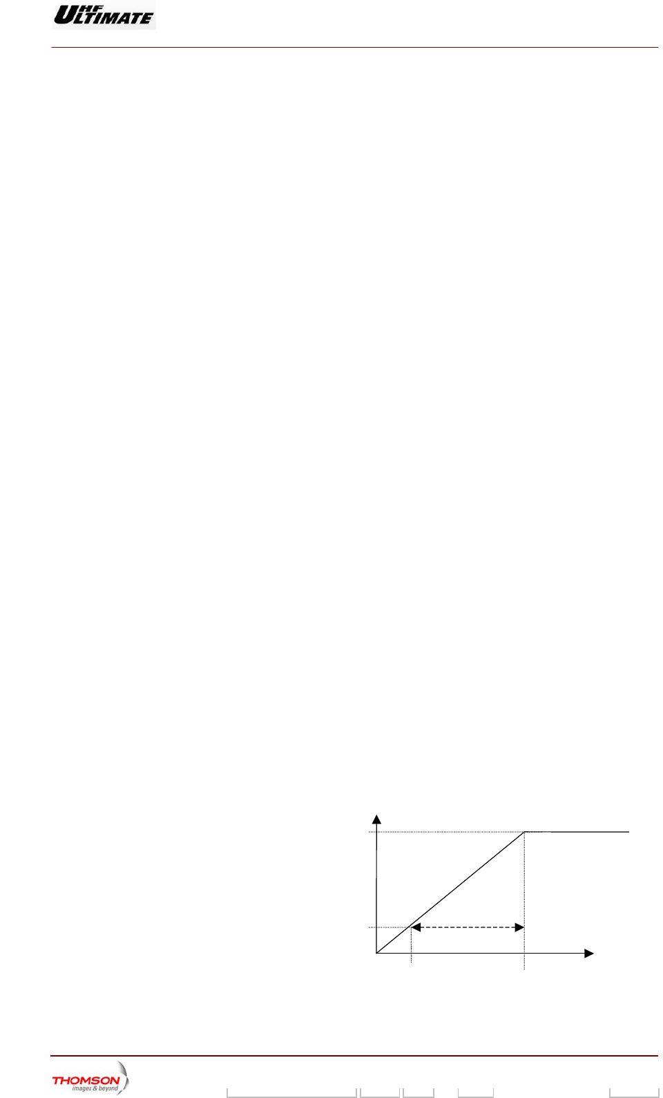
The quality assessments for the parameters are computed as follows:
♦ Quality assessment for Shoulder : NS = 20 – ((Measured value of parameter – CS )* 15 / S)
♦ Quality assessment for Ripple : NR = 20 – ((Measured value of parameter – CR )* 15 / R)
♦ Quality assessment for Power : NP = 20 – ((Measured value of parameter – PN )* 15 / P)
These equations provide the following
results:
♦ A quality assessment of 5 when the
difference between the Measured
value and the Correction threshold of
the parameter equals the Quality
threshold of the parameter.
♦ A quality assessment of 20 when the
Measured value of the parameter is
higher than or equal to the Correction
threshold. Measured value
of parameter
Correcting threshood
of
p
aramete
r
Quality threshold
of parameter
Quality
assessment of
parameter
20
05
When the quality assessment for one parameter is 5 while the other two assessments are 20, the
cubic root is 13. Such overall transmitter quality assessment is considered a major fault.

Digital Liquid Cooled UHF
TV Equipment
Detailed operational description
9946 V1
45321648.01 104 A E preliminary 29 / 131
Numéro / Number Doc. Rev. Lan
g
u. 16/06/2006 Pa
g
e
Information contained is this document is confidential, is THOMSON property and cannot be disclosed in whatever form without prior written authorization of THOMSON.
2.3.7. Data transfer between exciter and CPU
Basically the relationship between the Digital EMB and the UC Transmitter system can be categorised
as following:
♦ exchanges related to the basic working conditions: starting, restarting, stopping, safety ...
♦ exchanges related to the configuration of the Digital Exciter: modulator configuration (modes of
modulation, by pass of functions ...), DAP (modes of correction : On/Off, frozen, adaptive, ALE
On/Off and Adaptive/Fixed, Clipping On/Off and threshold ...)
♦ information wished by the customer: status of the digital Exciter (modes of modulation and
correction...), version, frequency and level of correction ...
♦ exchanges of files for backup and loading.

Digital Liquid Cooled UHF
TV Equipment
Detailed operational description
9946 V1
45321648.01 104 A E preliminary 30 / 131
Numéro / Number Doc. Rev. Lan
g
u. 16/06/2006 Pa
g
e
Information contained is this document is confidential, is THOMSON property and cannot be disclosed in whatever form without prior written authorization of THOMSON.
2.4. User interface operation
2.4.1. Outline
The operator can operate the transmitter from two locations:
♦ locally by using:
• a local control panel (PCL) which is positioned in the front panel of the main cabinet and
consists of:
- a screen in which various windows with transmitter commands and operational data are
displayed,
- indicator lamps which show operational status conditions,
- an LED system for showing the RF power level.
Note : Commands from the PCL can be locked (disabled) by using a password,
• an override switch (on/off) which is situated on the EXCITER/CPU interconnection mother
board.
♦ a remote location using a user interface which can be:
- a screen terminal connected via a serial link to the CPU card and which can display windows
on its screen which can be the same as or different from those on the PCL,
- a terminal consisting of status indicators for transmitter operation and commands which is
hard wired to the CPU card.
This user interface is positioned a few metres away from the transmitter (it can be about ten metres
away in the case of a serial link while it can be up to about 100 metres away in the case of a
hardwired connection).
A terminal can be connected to the Central Processing Unit and this provides facilities for examining
the transmitter log book.
2.4.2. Display control system
2.4.2.1. Outline
The "Display control system" controls:
♦ the display of data and messages on the windows of the PCL and of the remote user interface (in
the case of a serial link),
♦ the operation of the indicator lamps on the Local Control Panel (PCL),
♦ the status signals to the remote user interface (in the case of a hardwired connection).
The display control system receives all new status data and operator command data from the following
system operations: "polling of events", "polling of operator commands" and "command control
system".
The command control system receives manual commands from:
♦ the PCL, when the system is in local control and when the screen is unlocked, i.e. enabled by using
a password,
♦ the remote user interface when the system is in remote control mode.

Digital Liquid Cooled UHF
TV Equipment
Detailed operational description
9946 V1
45321648.01 104 A E preliminary 31 / 131
Numéro / Number Doc. Rev. Lan
g
u. 16/06/2006 Pa
g
e
Information contained is this document is confidential, is THOMSON property and cannot be disclosed in whatever form without prior written authorization of THOMSON.
2.4.2.2. Window control system
The window control system effects a real time update on the data base which contains the data to be
displayed in the various windows of the PCL or the remote user interface.
The updated data are sent to the PCL and to the remote user interface. Hence the database is
duplicated in the following sub units:
♦ Central processing unit,
♦ PCL,
♦ Remote user interface.
When the operator calls up a window to the PCL screen, the request is simultaneously sent to the PCL
database and to the CPU display system. The window together with its contents is then sent to the
PCL screen:
♦ either via the PCL data base if the windows are type A windows (“CONTROL”, “EXCITER”,
“INTLOCK”, “PSUPPLY”, ...). Type A windows do not contain any specific data linked to the
transmitter configuration.
♦ or, the data base attached to the display control system in the Central Processing Unit, if the
windows are type B windows ("AMPLI", "CONTROL OPER", "CONTROL MAINT",...). Type B
windows contain specific data linked to the transmitter configuration.
The remote user interface data from the data base can be used independently of the window call up
requests from the PCL (in the case of a serial link).
Control system for the hardwired connections
The processing of the hardwired commands and data system is supervised by the display control
system and deals mainly with events data from the "polling of events data" system.
Digital Liquid Cooled UHF
TV Equipment
Detailed operational description
9946 V1
45321648.01 104 A E preliminary 32 / 131
Numéro / Number Doc. Rev. Lan
g
u. 16/06/2006 Pa
g
e
Information contained is this document is confidential, is THOMSON property and cannot be disclosed in whatever form without prior written authorization of THOMSON.
CENTRAL PROCESSING UNIT (CPU)
POLLING OF
EVENTS DATA
Local control panel
Display
card RF signal status
Call-up request
for type A
windows
Data base for
window display
Update
Data base for
window display
Screen
locked
Transmitter commands
Remote
control
mode
Local
control
mode
Operator commands
Operator commands
Call-up request for
type B windows
Update of window
DISPLAY
MANAGEMENT
Update of data base + type B window
Local control mode
Screen unlocked
Reserve exciter on*
Manual exciter changeover
Manual on-air command
Changeover performed
Maintenance mode PCL INDICATOR
LAMPS CONTROL
SYSTEM
"Go home"indicator lit
Call-up
request for
type B
windows
CONTROL SYSTEM
FOR HARDWIRED
CONNECTIONS
REMOTE
USER
INTERFCE
(hardwired
connection)
Status data
Command data
DISPLAY CONTROL SYSTEM
* Only applies to the DD version
POLLING OF
OPERATOR
COMMANDS
Transmitter off-air
"On" indicator lit
RF power not correct
"Off" indicator lit
Local control mode
Screen unlocked "Unlock" indicator lit
Exciter changeover
impossible Buzzer
Transmitter on-air
Voyant "marche" allumé
1
Screen
unlocked COMMAND
CONTROL
SYSTEM
RF probes
Call-up
request for
data
Data base
Update
Remote user
interface
98/240c(e)
Exciter input : PRBS
Incoherent DAP
Figure 7 : Block diagram of PCL windows and indicator lamps control system
Digital Liquid Cooled UHF
TV Equipment
Detailed operational description
9946 V1
45321648.01 104 A E preliminary 33 / 131
Numéro / Number Doc. Rev. Lan
g
u. 16/06/2006 Pa
g
e
Information contained is this document is confidential, is THOMSON property and cannot be disclosed in whatever form without prior written authorization of THOMSON.
2.4.3. Power level bargraphs on PCL
The processing of the command signals which activate the PCL indicator lamps is mainly derived from
data from the "polling of events" system.
"Go home" indicator lamp
The "Go home" indicator lamp is illuminated when one of following events is detected:
♦ the transmitter is in local control mode,
♦ the transmitter is in maintenance mode,
♦ manual on-air/off-air switching mode has been selected,
♦ the PCL screen is unlocked,
♦ the manual exciter changeover mode has been selected (Dual Drive version only),
♦ an exciter changeover has already been carried out (Dual Drive version only),
♦ The reserve exciter is on (Dual Drive version only),
♦ The EXCITER status is NOT CONFORM (The operator chose a MODAP exciter and not a SIRIUS
exciter with the install mode)
♦ The input signal type of SIRIUS is a PRBS.
"On" indicator lamp
The "On" indicator lamp is illuminated when the transmitter is on-air.
"Off" indicator lamp
The "Off" indicator lamp is illuminated when the transmitter is switched off-air.
"Alarm" indicator lamp
The "Alarm" indicator lamp has three coloured segments and indicates the status of the RF power
levels based on the measurement from probe in the output of the amplifier channel:
♦ green: the RF power level is satisfactory,
♦ orange: the RF power level lies between the fault threshold and the low alarm threshold; these
levels can be set and monitored in the "RF LEVEL THRESHOLD" window of the PCL,
♦ red: the RF power level is higher than the high alarm threshold or lower than the fault threshold;
these levels can be set and monitored in the "RF LEVEL THRESHOLD" window of the PCL.
Fault
threshold
Low alarm
threshold
High alarm
threshold
0 dB
RED ORANGE
GREEN
RED
"Unlock" indicator lamp
The "UNLOCK" indicator lamp is illuminated when the PCL screen is unlocked and when the
transmitter is in local control mode.
The "UNLOCK" indicator lamp is extinguished when the PCL screen is locked (disabled) and when the
transmitter is in remote control mode.
Power level bargraphs on PCL
The illumination of the PCL bargraphs which display the RF power levels, is controlled by the PCL
display card, and varies with the measured values of the RF power levels from the reflectometer
probes on the output of the amplifier channel.

Digital Liquid Cooled UHF
TV Equipment
Detailed operational description
9946 V1
45321648.01 104 A E preliminary 34 / 131
Numéro / Number Doc. Rev. Lan
g
u. 16/06/2006 Pa
g
e
Information contained is this document is confidential, is THOMSON property and cannot be disclosed in whatever form without prior written authorization of THOMSON.
2.4.4. Log book control system
Each new event, which is detected by the system, is recorded in the logbook; each event is given a
title and is dated. The last 500 events can be stored.
The operator has the facilities to control the flow of information which is sent to the log book terminal
by using the Local Control Panel.
2.4.5. On/Off commands and change-over override switch
2.4.5.1. Controls
The transmitter configuration can be controlled by override switches mounted on the exciter/CPU
interconnection card mother board as follows :
♦ SW1 : switches the transmitter to installation mode,
♦ SW2 : switches the transmitter on if the CPU is faulty or not present,
♦ SW3 : switches the transmitter off if the CPU is faulty or not present,
♦ SW4 : switches exciter A to air if the CPU is faulty or not present,
♦ SW5 : switches exciter B to air if the CPU is faulty or not present.

Digital Liquid Cooled UHF
TV Equipment
Description / Test points / Location of units
9946 V1
45321648.01 104 A E preliminary 35 / 131
Numéro / Number Doc. Rev. Lan
g
u. 16/06/2006 Pa
g
e
Information contained is this document is confidential, is THOMSON property and cannot be disclosed in whatever form without prior written authorization of THOMSON.
3. Description / Test points / Location of units
3.1. System architecture and location of transmitter units
The Dual Drive version of the transmitter consists of the following units:
♦ a unit containing two exciters in a redundant switchover system whereby a faulty exciter is replaced
by the other. After digital processing, it transposes the input MPEG signals into a RF output.
Each digital exciter consists of:
• A SIRIUS rack with :
A DVB-T (Europe) modulator board , ATSC (America) modulator board or MédiaFLO modulator
board
a processing signal board,
an RF synthesiser,
a preamplifier,
a Very Low Voltage power supply,
• In the management rack, a RF amplifier (for DVB-T and ATSC modulator only)
♦ a coaxial relay and its 50 Ohms load so that one of the two digital exciters can be switched on RF
amplifier channel.
♦ an RF amplifier way,
♦ a filter unit which filters the RF signal,
♦ a control system as follows:
• A Central Processing Unit (CPU) which supervises the operation of the transmitter electronics
units depending on operator commands and the status conditions in the units.
• the very low voltage power supply for the CPU and the PCL,
• an exciter/CPU interconnection card,
♦ a multiplex card which is the connection unit between the Central Processing Unit and the main
transmitter electronic units,
♦ a Local Control Panel (PCL) which controls the data interchange between the operator and the
transmitter,
♦ a Mains Distribution Panel which provides the mains feeds for the various transmitter power
supplies,
♦ the power supplies for the RF amplifiers,
♦ the cooling system for the Exciter/CPU system.
The following associated external sub-systems for the SD/DD transmitters combine together to form a
complete transmission operation:
♦ an external cooling system to cool the transmitter,
♦ an input three-phase mains supply,
♦ an external changeover system so that the transmitter can be switched between a dummy load and
the antenna,

Digital Liquid Cooled UHF
TV Equipment
Description / Test points / Location of units
9946 V1
45321648.01 104 A E preliminary 36 / 131
Numéro / Number Doc. Rev. Lan
g
u. 16/06/2006 Pa
g
e
Information contained is this document is confidential, is THOMSON property and cannot be disclosed in whatever form without prior written authorization of THOMSON.
♦ A remote user interface (optional) with facilities for remote control of the transmitter.
Simple Drive transmitter
The Single Drive version is physically different from the Double Drive version in that it only has one
digital exciter .
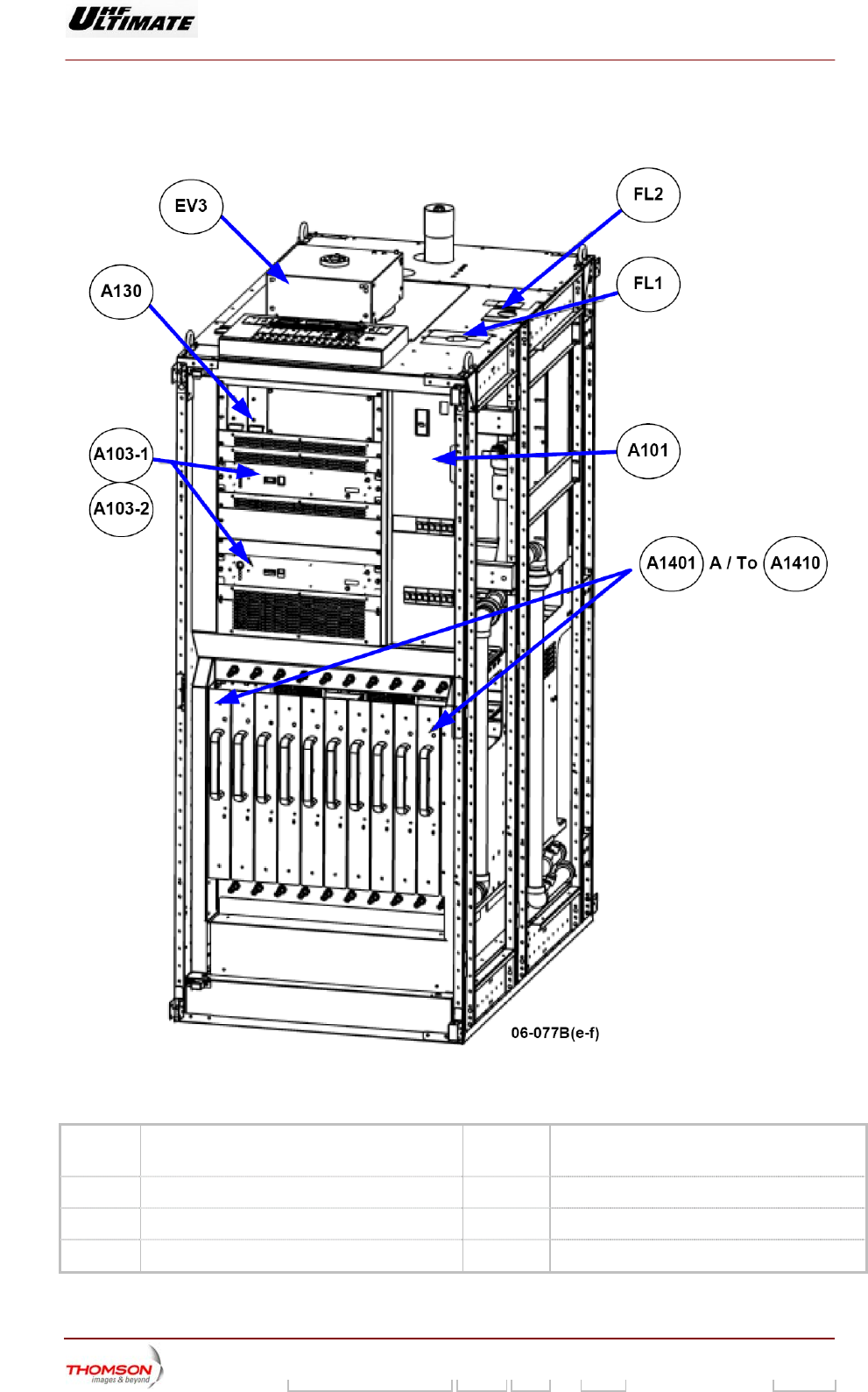
Digital Liquid Cooled UHF
TV Equipment
Description / Test points / Location of units
9946 V1
45321648.01 104 A E preliminary 37 / 131
Numéro / Number Doc. Rev. Lan
g
u. 16/06/2006 Pa
g
e
Information contained is this document is confidential, is THOMSON property and cannot be disclosed in whatever form without prior written authorization of THOMSON.
3.1.1. Location of transmitter units
Figure 8 : Localisation of the main units in front of the cabinet B860
EV3 Exhaust fan A1401 to
A1410
RF amplifier units
A130 Gestion rack (Management rack) A101 Energy plate
A103-1 Exciter A FL1 Mains filter
A103-2 Exciter B (DD configuration only) FL2 Mains filter for emergency mains input
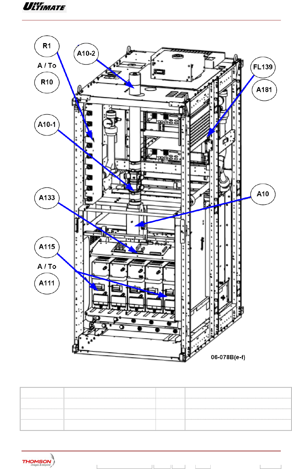
Digital Liquid Cooled UHF
TV Equipment
Description / Test points / Location of units
9946 V1
45321648.01 104 A E preliminary 38 / 131
Numéro / Number Doc. Rev. Lan
g
u. 16/06/2006 Pa
g
e
Information contained is this document is confidential, is THOMSON property and cannot be disclosed in whatever form without prior written authorization of THOMSON.
Figure 9 : Localisation of the mains units in rear of the cabinet B860
R1 to R10 Loads network for the F.I.C.S A10 RF Amplifier combiner (FICS)
A10-1 Measuring probes A181 ASI Splitter
A133 Multiplex board FL139 Channel Filter
A115 to A111 Power supply unit A10-2 Harmonic filter
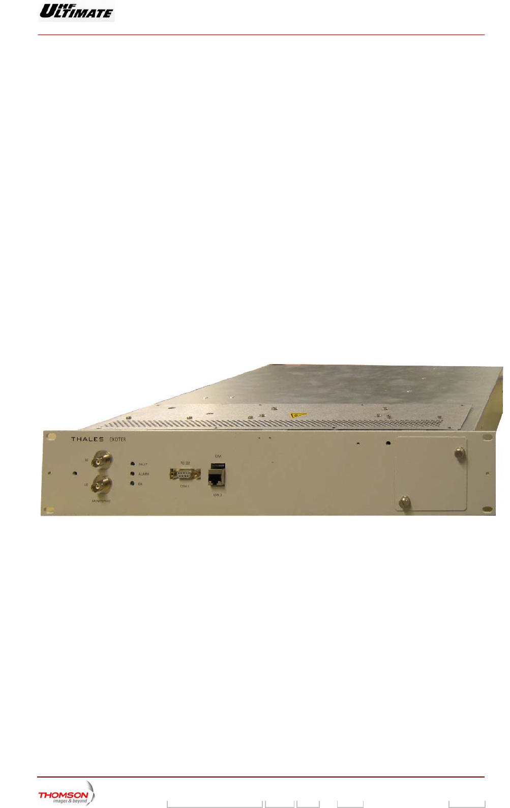
Digital Liquid Cooled UHF
TV Equipment
Description / Test points / Location of units
9946 V1
45321648.01 104 A E preliminary 39 / 131
Numéro / Number Doc. Rev. Lan
g
u. 16/06/2006 Pa
g
e
Information contained is this document is confidential, is THOMSON property and cannot be disclosed in whatever form without prior written authorization of THOMSON.
3.2. Rack : SIRIUS DVB-T UHF 45321627.11
3.2.1. Introduction
The sirius exciter is a key element for Media FLOTM transmitting technolongy
The quality of coding and modulation is particularly important to the MediaFLO process. Hence the
Sirius exciter has been designed to fulfil the most demanding requirements with respect to
performance as well as flexibility in application and operation. Strict adherence to the MediaFLO
system specifications is of course a must, but also additional features have been added to the exciter
to enhance the value of a given transmission system. Thus emphasis has been placed on easy
interfacing to both the signal distribution system and, in particular, to the final TV transmitter, to ensure
maximum transmitter coverage at the lowest cost.
Although the TV signal for MediaFLO is coded in a very robust way, thus making it quite rugged, the
fact remains that once it is coded and modulated into a MediaFLO physical layer. The exciter
compensates the traditional distortions and impairments known from analogue TV will take over in a fast
and efficient way.
In digitally transmitted TV signals, factors like noise, inter modulation and non-linearity play a much
larger role than in analogue TV signals as they may very well prevent reception and decoding as a
whole. This means that the analogue performance of a COFDM exciter is of utmost importance. In the
case of the Sirius exciter special thought has been given to the design of the areas that have an influence on the
analogue performance.
06/095(e-f)

Digital Liquid Cooled UHF
TV Equipment
Description / Test points / Location of units
9946 V1
45321648.01 104 A E preliminary 40 / 131
Numéro / Number Doc. Rev. Lan
g
u. 16/06/2006 Pa
g
e
Information contained is this document is confidential, is THOMSON property and cannot be disclosed in whatever form without prior written authorization of THOMSON.
3.2.2. Applications
The sirius exciter is designed to serve three functions for MediaFLO, i.e., channel coding, RF
modulation and manages analogue interface to the transmitter. The exciter, which complies with the
MediaFLO Air interface specification, provides the basic functions of converting an MPEG transport
stream and converting the resulting data to a MediaFLO modulated IF signal.
The exciter supports the 4K operating mode and mandatory SFN operation.
The primary application is as a terrestrial TV transmitter exciter and thus special attention has been paid to
optimizing the total transmitter performance. The COFDM signal itself is very complex with respect to
frequency and amplitude and non-linear behaviour of the transmitter power amplifier will cause
difficulties for reception as well as interference into adjacent channels. Hence the unit is equipped with
an adaptive amplitude and phase non-linearity pre-corrector which digitally optimizes the transmitter
performance and thus increases the coverage area available at a given output power level Moreover
an adaptive linear-pre-corrector is implemented to compensate eventual amplitude and phase
inconveniences of combiner filters etc.
Also due to the complexity of the COFDM signal, the alignment of transmitters is cumbersome.
However the built-in test signals greatly facilitate this alignment.

Digital Liquid Cooled UHF
TV Equipment
Description / Test points / Location of units
9946 V1
45321648.01 104 A E preliminary 41 / 131
Numéro / Number Doc. Rev. Lan
g
u. 16/06/2006 Pa
g
e
Information contained is this document is confidential, is THOMSON property and cannot be disclosed in whatever form without prior written authorization of THOMSON.
3.2.3. SIRIUS Description
The inputs are MPEG transport stream(s) carrying information about the program content, the number
of programs and the program data. The standard MPEG transport stream format is ASI (Asynchronous
Serial Interface).
Before modulation the signal is subjected to a heavy error protection process and various interleaving processes.
By these means the receiver will work even during bad transmission conditions and be able to regenerate the
signal in most situations.
The digital exciter SIRIUS is composed of a box in which are mounted some digital cards:
♦ A programmed MediaFLO (FPGA) digital card (rep.1)
♦ A TS/TV card (rep.2)
♦ A TX card (rep.3)
♦ A filter card (rep.4)
♦ A switch/ALE card (rep.5)
♦ A RF preamplifier unit (rep.6)
♦ A RF synthesizer unit (rep.7)
There are also some elements which are:
♦ A main power supply unit(rep.8)
♦ A cooling unit (rep.9) including 2 fans (rep.10)and one PSU (rep.11)
♦ A GPS receiver (option) (rep.12)
♦ A signalization card (LED) (rep.13)
The here after figure shows the main card location of the MediaFLO SIRIUS exciter.
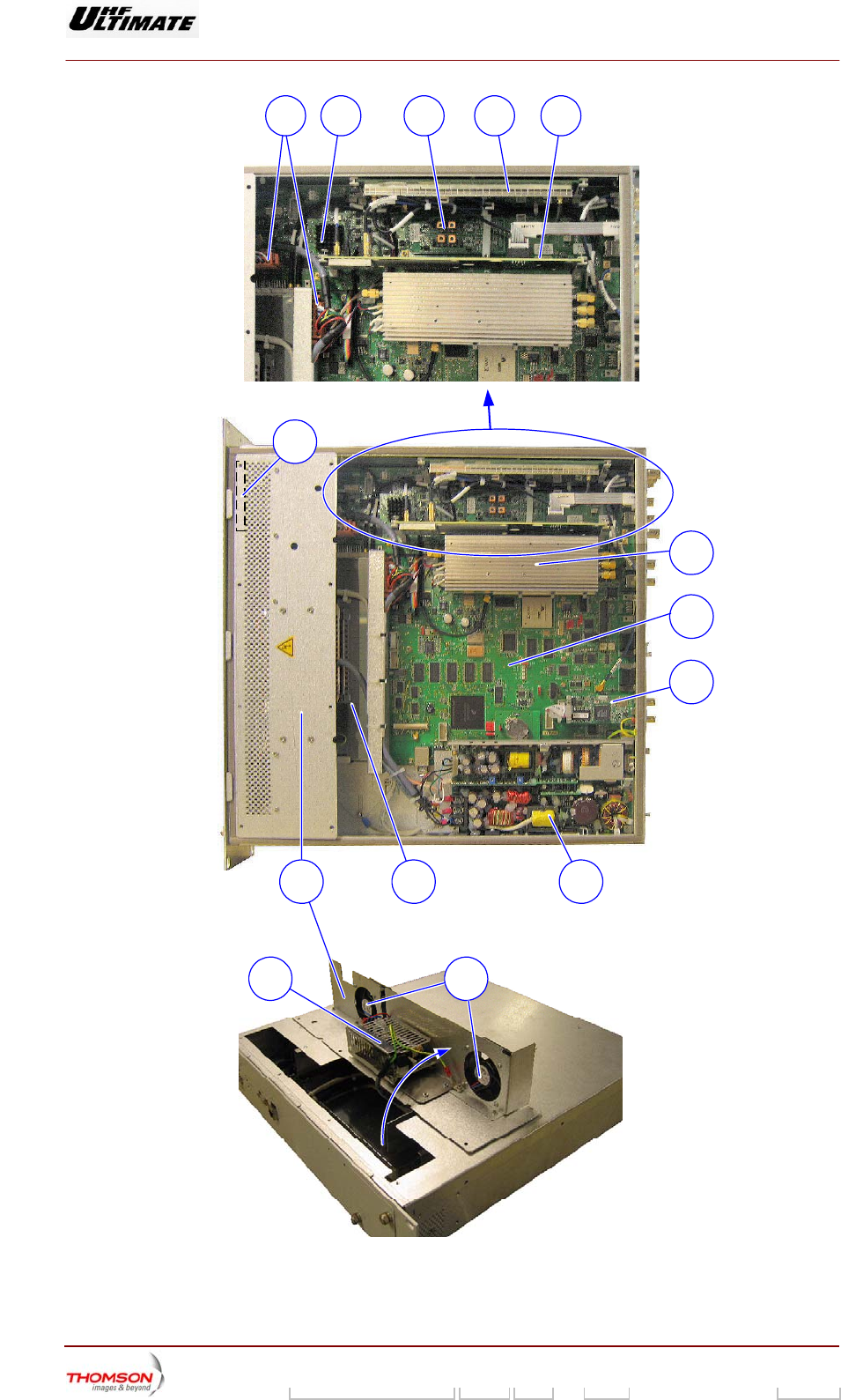
Digital Liquid Cooled UHF
TV Equipment
Description / Test points / Location of units
9946 V1
45321648.01 104 A E preliminary 42 / 131
Numéro / Number Doc. Rev. Lan
g
u. 16/06/2006 Pa
g
e
Information contained is this document is confidential, is THOMSON property and cannot be disclosed in whatever form without prior written authorization of THOMSON.
06/103(e-f)
28A 4 53
1011
1
6
789
12
13