Thomson Broadcast and Multimedia ULT-1K10K2 UHF Digital transmitter, for use with MediaFlo User Manual PREIMPAP
Thomson Broadcast & Multimedia, Inc. UHF Digital transmitter, for use with MediaFlo PREIMPAP
Contents
Operation manual part 3

Digital Liquid Cooled UHF
TV Equipment
Description / Test points / Location of units
9946 V1
45321648.01 104 A E preliminary 86 / 131
Numéro / Number Doc. Rev. Lan
g
u. 16/06/2006 Pa
g
e
Information contained is this document is confidential, is THOMSON property and cannot be disclosed in whatever form without prior written authorization of THOMSON.
3.10.5. Test points
Connector J1 on the front of the panel provides a test monitoring
feed of the amplifier RF output signal.
3.10.6. Adjustment controls
There is a potentiometer control (R164) on the front panel of each
RF amplifier module which is used to set the AGC voltage of each
power amplifier to the same value.
3.10.7. Protection and surveillance devices
The protection card protects the amplifier using surveillance signals as follows :
♦ protection against degradation of SWR performance at the amplifier output: this surveillance device
is triggered when the SWR value is greater than 2.
♦ protection system against high currents in the amplifier LDMOS transistors: a fast acting current
measuring system detects an abnormal current increase in the transistors. The surveillance device
is triggered at a current I > 45 A for a block of 4 double transistors (2 amplifier modules).
♦ thermal protection system: when the input air temperature is greater than 60°C inside the amplifier
the amplifier is automatically switched off.
♦ under-voltage protection device is triggered when the DC supply drops below 24 V.
In all of the above protection systems, when a particular threshold parameter is reached, the amplifier
is protected by attenuating the input signal (by 20 dB). In case of overheating and/or overvoltage, the
amplifier is protected by an immediate shutdown by rapidly changing the transistor bias voltages.
To re-start the amplifier a reset command from the Central Processing Unit is necessary.
Digital Liquid Cooled UHF
TV Equipment
Description / Test points / Location of units
9946 V1
45321648.01 104 A E preliminary 87 / 131
Numéro / Number Doc. Rev. Lan
g
u. 16/06/2006 Pa
g
e
Information contained is this document is confidential, is THOMSON property and cannot be disclosed in whatever form without prior written authorization of THOMSON.
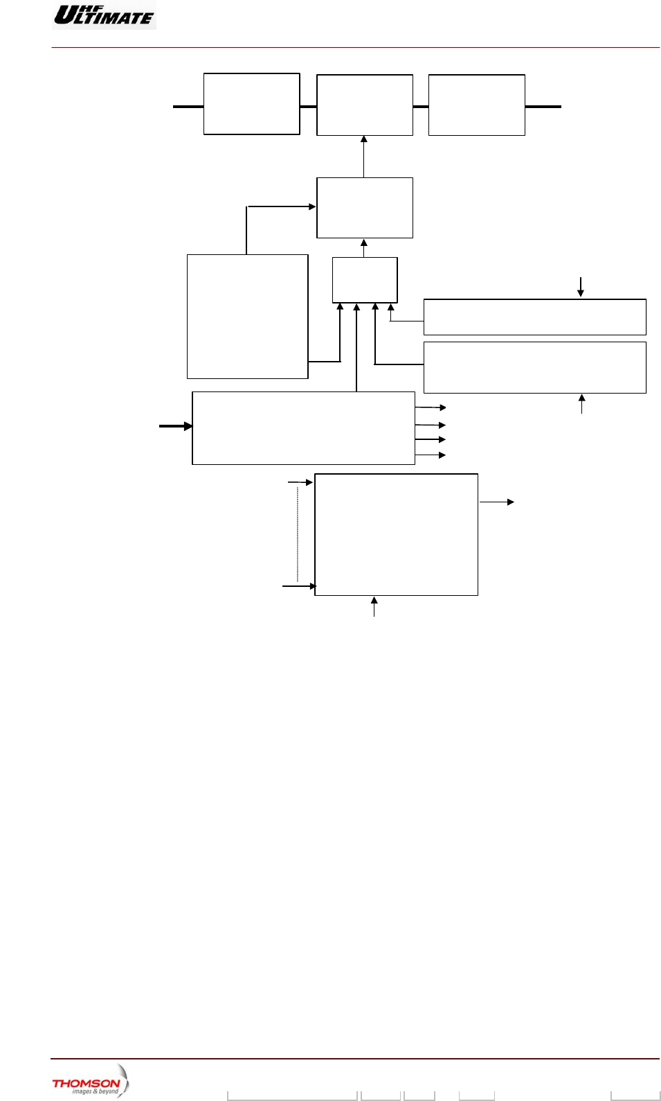
Fixed
attentuator Variable
attenuator Phase
shifter
Gain
control
Temperature
compensation
&
protection SWR protection & storage
Overcurrent protection &
stora
g
e
OR
Power supply
-10V
+5 V
+12V
+28V
+30V
Fault detection
Auto-diagnostic
system
Input power
Output power
Current fault with/without Pw
SWR fault
Overcurrent fault
Power supply fault
Temperature fault
Amplifier fault
Reset
Reset
Reset
Power supply protection
All the above fault signals, i.e. VSWR, overcurrent and temperature are sent to the Central Processing
Unit card after validation. Validation consists of checking the internal supplies (+5 V and -10 V) and
the external supplies (> 24 V).
The auto-diagnostic «amplifier fault» signal is a logical 1 output from a logical «Or» gate with the
following fault inputs :
♦ VSWR,
♦ transistor over-current (measurement of current of 2 amplifier modules),
♦ temperature,
♦ RF transistor failure,
♦ low RF power output,
♦ internal power supply fault.
The absence of an external power supply fault (> 24 V) validates the auto-diagnostic system and
sends the validation signal to the CPU card.

Digital Liquid Cooled UHF
TV Equipment
Description / Test points / Location of units
9946 V1
45321648.01 104 A E preliminary 88 / 131
Numéro / Number Doc. Rev. Lan
g
u. 16/06/2006 Pa
g
e
Information contained is this document is confidential, is THOMSON property and cannot be disclosed in whatever form without prior written authorization of THOMSON.
3.10.8. Power input
The amplifier is powered with DC voltage from an amplifier power supply. One of the incoming voltage
power connectors J1 or J6 is connected to the input power connector, J1 or J6, on the back of the
amplifier.
The amplifier is also fed by a +5 V supply from the multiplex card on the connector J106/J107, this is
only used if there is a problem with the +5 V supply provided by the protection and interface card.
3.10.9. Connections and data transfer
The amplifier has the following connectors :
♦ on front panel :
• connector J1, amplifier RF output test point,
• two self-locking hydraulic connector,
♦ on rear panel :
• coaxial connector J2, RF output signal,
• coaxial connector J104, RF input signal,
• input power supply connector for the DC incoming feed,
• connector J106/J107, for connections with the rest of the transmitter;
the main signals are as follows :
- amplifier status data :
VSWR fault,
overdrive fault,
temperature fault,
power supply fault,
amplifier presence,
amplifier fault,
transistor current values and AGC information
- amplifier command data :
reset command for vswr protection system and current and
temperature protection systems, on/off command,
- 5 V supply from the multiplex card.
3.10.10. Cooling
The amplifier has a cooling circuit. The cooling liquid from the transmitter system enters via a self-
locking connector on the amplifier, circulates through the power amplifier heat exchange system and
exits via a second connector; both connectors are on the amplifier front panel.
3.10.11. Transportability
The amplifier weighs 19 kg and it is necessary to take precautions when moving it. It has a handle on
the front panel which is used to extract it from its housing in the bay. For transportation purposes it has

Digital Liquid Cooled UHF
TV Equipment
Description / Test points / Location of units
9946 V1
45321648.01 104 A E preliminary 89 / 131
Numéro / Number Doc. Rev. Lan
g
u. 16/06/2006 Pa
g
e
Information contained is this document is confidential, is THOMSON property and cannot be disclosed in whatever form without prior written authorization of THOMSON.
removable handle (ref. 91 568 218) which can be inserted into the upper part of the heat sink. A
marine type enclosure including custom-built wrapping is used to house the amplifiers in complete
safety during long journeys.
3.10.12. Environmental Conditions
Liquid temperature for guaranteed specifications : 0 to 55 °C.
Liquid temperature for guaranteed operation : -10 to 60°C.
Storage temperature (ampli empty) : .-30 to 60 °C.
Maximum altitude in operation : 3000 m.
Relative humidity : 95 % without condensation.
Cooling : Water + glycol (50% diluted) + corrosion inhibitor
3.10.13. Electrical Characteristics
The electrical characteristics below are given for above environmental conditions, 50 V mains supply
and nominal liquid flow of 6l/min.
Input max. level without destruction: 20 dBm max.
Output power (2 dB compression on VSWR ≤ 1.2 and 650 ≤ F ≤ 750 MHz): 2100 W min.
Continuous power in CW sinusoidal mode : 960 W max.
Instantaneous bandwidth : 650 to 750 MHz.
Gain at 719 MHz for Ps=570 W CW : 63 ± 0.2 dB.
Gain linear distortions (650 to 750 MHz for Ps=960 W CW): ±0.75 dB max. ±1.5 dB
Reference electrical length at 720 MHz : 27.64 ns. ± 5 ns
Gain flatness between amplifiers (with selective under band switch) : ± 0.3 dB max.
Phase flatness between amplifiers : ± 10 ° max.
Gain tilt in bandwidth : 0.1 dB/MHz max.
Phase tilt in bandwidth : 1 °/MHz max.
Max. consumed current at 1000 W r.m.s : 115 A.
Minimum efficiency at 570 W r.m.s : 23 %.
Input matching in bandwidth : 17 dB min.
Output matching in bandwidth: 14 dB min.
Harmonic level for Ps=1600 W peak on 50 Ohms load : H2......26 dB min.
Front face coupling sample : 49 dB ± 1 dB.
Shoulder level without correction on multi carrier signal, (8 MHz band, 1600 W PEP): 25 dB.
Thermal protection (Temperature measured on slab) : 80 ± 5 °C.
Guaranteed max. pressure (airtight-Ness) : 7 bars.
Shoulders for Ps = 570 W r.m.s (with MODAP) : -36 dBc max.
MER for Ps= 570 W r.m.s (with MODAP) : 33 dB min.
Transistor junction temperature (liquid temperature = 60°C for 960 W CW) : < 170°C max.
Min. liquid flow : 5l/min.
3.10.14. Physical characteristics
Measurements with handle (L x H x P) : 70x600x720 mm.
Weight : 19 kg max.

Digital Liquid Cooled UHF
TV Equipment
Description / Test points / Location of units
9946 V1
45321648.01 104 A E preliminary 90 / 131
Numéro / Number Doc. Rev. Lan
g
u. 16/06/2006 Pa
g
e
Information contained is this document is confidential, is THOMSON property and cannot be disclosed in whatever form without prior written authorization of THOMSON.
3.11. Amplifier power supply, 37419700.02
3.11.1. Outline
The amplifier power supply contains the following sub-units :
♦ filter unit,
♦ diode bridge,
♦ PFC card together with boost inductors,
♦ control card containing :
• circuits for current limitation, mains protection and surveillance devices,
• two DC/DC converters,
• monitoring system,
♦ step down transformer,
♦ output «LC» filter circuit,
♦ output signals interface card.
Digital Liquid Cooled UHF
TV Equipment
Description / Test points / Location of units
9946 V1
45321648.01 104 A E preliminary 91 / 131
Numéro / Number Doc. Rev. Lan
g
u. 16/06/2006 Pa
g
e
Information contained is this document is confidential, is THOMSON property and cannot be disclosed in whatever form without prior written authorization of THOMSON.
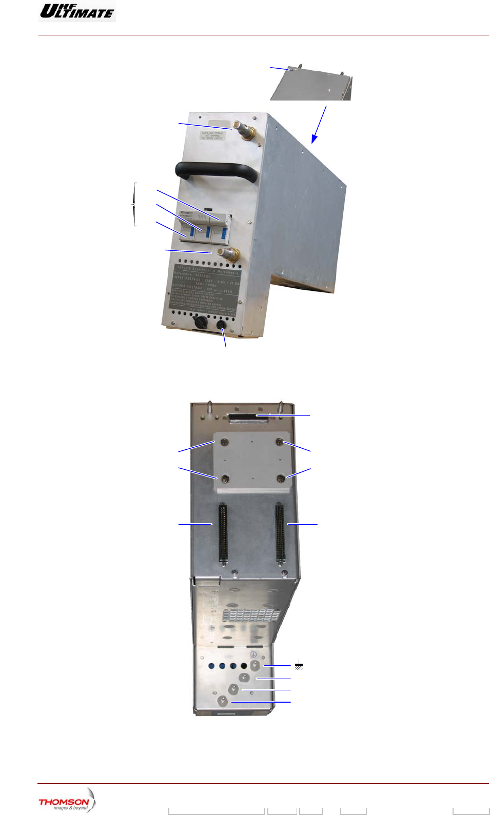
Connector
to amplifier
06/089(e)
Connector to
amplifier
J1
to control unit
J6
Interlock with
amplifiers
06/088 (e)
J3
Interlock with
amplifiers
Green Led
output voltage
present
F2
F3
F4
F1
J2
(R)
(+) J5 (R)
(+)
PH1
PH2
PH3
S1
06/086(e)
Hydraulic
Connector
Renoval
handle
Hydraulic
Connector
Lock system
Figure 20 : Liquid cooled power supply

Digital Liquid Cooled UHF
TV Equipment
Description / Test points / Location of units
9946 V1
45321648.01 104 A E preliminary 92 / 131
Numéro / Number Doc. Rev. Lan
g
u. 16/06/2006 Pa
g
e
Information contained is this document is confidential, is THOMSON property and cannot be disclosed in whatever form without prior written authorization of THOMSON.
3.11.1.1. Operational description
The input three phase mains supply passes through protection fuses F1 to F3, and then passes
successively through the following :
♦ filter unit (FL1) for parasite elimination,
♦ circuit for current limitation and mains protection and surveillance devices.
The mains supply is then rectified by a diode bridge rectifier (CR1) followed by a PFC circuit (boost
inductance + PFC card).
The resulting DC voltages are fed to a PFC card which improves the power factor of the incoming
mains by :
♦ arranging that incoming current is totally sinusoidal,
♦ reducing the harmonics.
The PFC card has two choppers separated by a phase delay of 90°. The currents are added and fed
to two DC/DC converters in an H bridge configuration and installed on the control card.
A pulse width modulating circuit which is controlled by the output voltage is used to control the
waveform pulse width. This is the basic mechanism for controlling the output voltage.
This modulating circuit which is synchronised to the PFC card uses control circuits to control the
operation of the H bridges so that the waveform is shaped properly and the chopping action is
synchronised.
The pulse width modulation circuit is fed by an auxiliary 24 V DC fed from a step-down transformer
followed by rectification and filtering.
Each DC/DC converter feeds a transformer primary winding. The unidirectional voltage cycles from the
secondary winding go through a further push-pull rectifying circuit followed by an «LC» filtering circuit
and the resulting voltage is then fed to the power supply module output.
Each amplifier power supply has an output interface card containing logic circuits which :
♦ generate power supply start-up and shut-down commands (see § «Surveillance devices»),
♦ control the output voltage and adjust it to the set value. The set value is encoded into a 3 bit word
which is sent by the multiplex card and can be set by using internal switches in the multiplex card
(this only applies to the Ultimate range of UHF transmitters).
Note : On high power transmitters all command and status data exchanged between the multiplex
card and the RF power amplifiers pass through the amplifier power supplies.
Digital Liquid Cooled UHF
TV Equipment
Description / Test points / Location of units
9946 V1
45321648.01 104 A E preliminary 93 / 131
Numéro / Number Doc. Rev. Lan
g
u. 16/06/2006 Pa
g
e
Information contained is this document is confidential, is THOMSON property and cannot be disclosed in whatever form without prior written authorization of THOMSON.
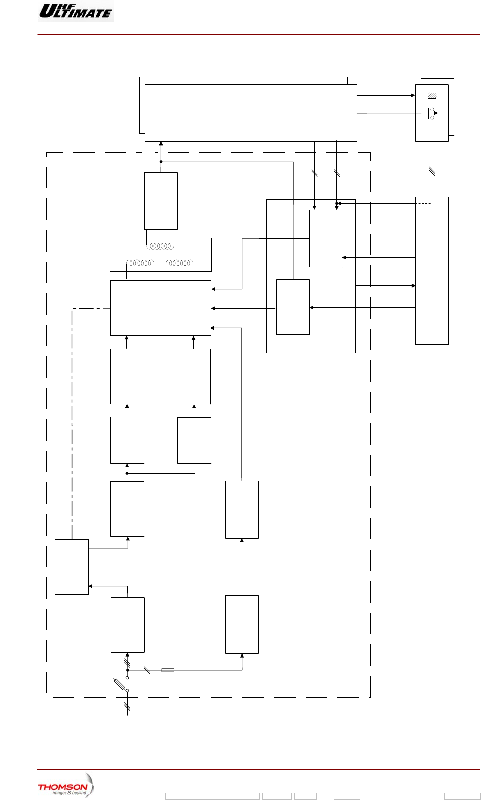
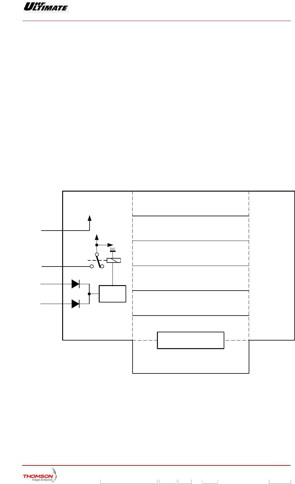
START-UP
CONTROL CIRCUIT
RECTIFIER/FILTER
(LC)
TRANSFORMER
AMPLIFIER
Amplifier presence
signals
MULTIPLEX CARD
Power supply
unit status data
On command
INTERFACE
CARD
Amplifier 1 (and 2)
extracted
Start-up command
(shut down)
U regul.
CONTACTS
PRESENT
DC power
supply output
OUTPUT VOLTAGE
REGULATION
DC/DC
CONVERTERS
MAINS LIMITATION/
PROTECTION/
SURVEILLANCE
MAINS FILTER
(FL1)
BOOST
INDUCTOR
TRANSFORMER RECTIFIER/FILTER
Mains
S1
POWER SUPPLY UNIT
24V DC
06/092 (e)
RECTIFIER (CR1)
BOOST
INDUCTOR
POWER FACTOR
CORRECTION
(PFC CARD)
Output voltage
value
Amplifier 1 (and 2)
present
F1
Figure 21 : Block diagram of an amplifier power supply
Digital Liquid Cooled UHF
TV Equipment
Description / Test points / Location of units
9946 V1
45321648.01 104 A E preliminary 94 / 131
Numéro / Number Doc. Rev. Lan
g
u. 16/06/2006 Pa
g
e
Information contained is this document is confidential, is THOMSON property and cannot be disclosed in whatever form without prior written authorization of THOMSON.
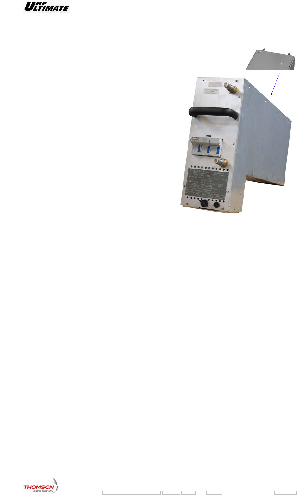
3.11.1.2. Using the commands
The amplifier power supplies are fed via a switch
fuse isolator for protection of the power supply,
accessible to the operator on the front panel.
3.11.1.3. Indicator lamps and message
displays
A green LED on the upper panel indicates the
status of the power supply as follows :
♦ when lit up it indicates that there is an output
DC voltage and that the power supply is in
operation,
Green Led
output voltage
present
06/086(e)
♦ when extinguished it indicates that there is no output DC voltage and that the power supply is shut
down or faulty.
Note : The «POWER SUPPLY» window which can be displayed on the PCL displays the status
conditions for the power supplies in a bay as follows :
♦ POWERED OFF : power supply shut down but fault-free,
♦ POWERED ON : power supply in operation and fault-free,
♦ FAULT : mains input failure; this indication is independent of the power
supply operational status (on or off),
♦ MISSING : power supply absent,
♦ BREAKER OFF : fused isolator open circuited,
♦ MAINS FAULT : one of the mains fuses F1 to F3 has failed,
♦ UNKNOW : internal power supply fault in the multiplex card.
3.11.1.4. Test points
The amplifier power supply has no test points.
3.11.1.5. Adjustment controls
The amplifier power supply has no adjustment controls available to the operator.
3.11.1.6. Protection and surveillance devices
Each power supply module is protected against high input currents by internal fuses (F1 to F3) in the
mains input feed.

Digital Liquid Cooled UHF
TV Equipment
Description / Test points / Location of units
9946 V1
45321648.01 104 A E preliminary 95 / 131
Numéro / Number Doc. Rev. Lan
g
u. 16/06/2006 Pa
g
e
Information contained is this document is confidential, is THOMSON property and cannot be disclosed in whatever form without prior written authorization of THOMSON.
The mains supply to the module can be switched off by an isolator on the front panel ; fuses F1 to F3
can be accessed when the isolator is open.
The control card has a mains circuit with the following protection and surveillance devices:
♦ a current limitation circuit which is active on power supply start-up,
♦ protection against mains overvoltages (surge arresters),
♦ a mains surveillance device (loss of a phase, under-voltage, overvoltage) which can switch on or
switch off the power supply module,
♦ an EC (Electromagnetic Compatibility) filtering circuit.
The output interface card has a switch on/switch off circuit which monitors the connection status of the
amplifiers :
♦ Each amplifier has the capability of sending data when it is present and when it is withdrawn.
These data in addition to the On command (shut-down circuit) trigger the start-up of the power
supply,
♦ when an amplifier is withdrawn :
• the disappearance of the presence data causes the power supply to be shut down,
• after the extraction of the amplifier the opening of the withdrawal contact triggers the restart-up
of the power supply,
♦ during the insertion of an amplifier :
• the closing of the withdrawal contact triggers the shut-down of the power supply,
• the presence data triggers the switch on of the power supply,
♦ The withdrawal of the two amplifiers connected to a particular power supply triggers the total shut-
down of the power supply even if the on command (shut-down circuit) is continued.
A thermal surveillance device triggers the shut-down of the power supply when the temperature rises
beyond 75°C.
3.11.1.7. Connections and data transfer
Each power supply is connected to other installation equipment via the following connectors :
♦ J1 : connections to the multiplex card,
♦ J2 and J5 : +30 V DC output connectors to feed the power amplifiers,
♦ J3 and J6 : connectors on the power amplifiers of high power transmitters.
These connectors carry command and status data exchanges between the multiplex card and the
amplifiers,
♦ not connected on medium power transmitters,
♦ power connector (phases 1, 2 and 3 and earth) : mains input feed termination.
3.11.1.8. Power input
The three phase mains input supply is fed to each amplifier power supply module from the Mains
Distribution Panel. Each module is connected to the mains supply via a power connector on the back
of the module, in the bottom.

Digital Liquid Cooled UHF
TV Equipment
Description / Test points / Location of units
9946 V1
45321648.01 104 A E preliminary 96 / 131
Numéro / Number Doc. Rev. Lan
g
u. 16/06/2006 Pa
g
e
Information contained is this document is confidential, is THOMSON property and cannot be disclosed in whatever form without prior written authorization of THOMSON.
3.11.1.9. Cooling
The power supply unit has a cooling circuit. The cooling liquid from the transmitter system enters via a
self-locking connector on the amplifier, circulates through the power supply heat exchange system and
exits via a second connector; both connectors are on the power supply front panel.

Digital Liquid Cooled UHF
TV Equipment
Description / Test points / Location of units
9946 V1
45321648.01 104 A E preliminary 97 / 131
Numéro / Number Doc. Rev. Lan
g
u. 16/06/2006 Pa
g
e
Information contained is this document is confidential, is THOMSON property and cannot be disclosed in whatever form without prior written authorization of THOMSON.
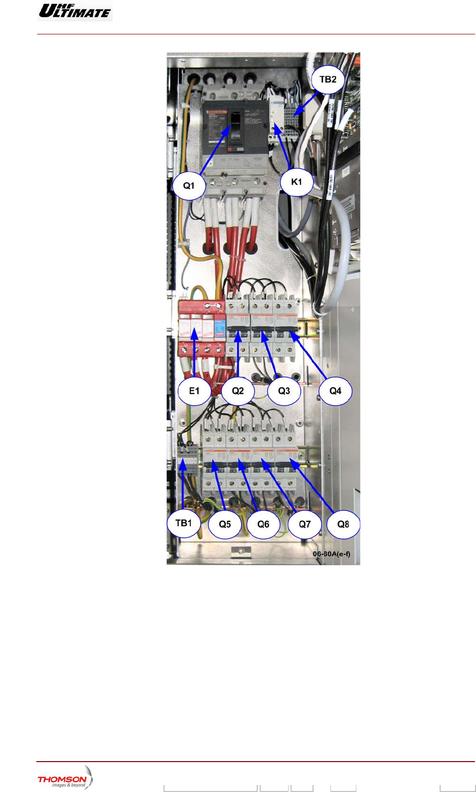
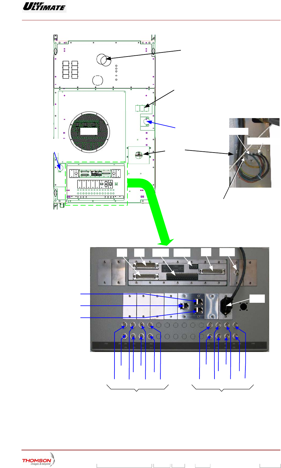
3.12. The mains plate, 61391643
3.12.1. Outline
The Mains Distribution Panel takes in the external main supply and provides mains feeds together with
protection systems for the various transmitter sub-units and the incoming mains supply.
The Mains Distribution Panel has safety devices to protect against abnormalities in the incoming main
supply as follows:
♦ main circuit breaker Q1, which isolates the mains supply from the equipment and is the principal
safety switch. Moreover it protects the transmitter against overload conditions.
♦ over voltage protection E1 module.
The status conditions of the incoming main supply are transmitted to the loop protection system and
the Central Processing Unit by data from the following sensors:
♦ a contact Q1-1 on the main circuit breaker Q1,
♦ a mains monitoring relay K1 which detects the presence, absence and phase inversion of the three
phases of the incoming mains supply.
♦ a mains monitoring relay E1 which detects the lighting protection of the three phases of the three
phases of the incoming mains supply.
The Mains Distribution Panel provide selective protection for the installation so that only the protective
device immediately ahead of the fault will be activated :
• Circuit breaker Q6 : protects the mains feeds of the very low voltage power supply for the
Control Processor Unit via the management rack,
• Circuit breaker Q7 : not used,
• Circuit breaker Q8 : protects the mains feeds of external exhaust fan EV3.
• Circuit breaker Q5 : protects the mains feeds of an uninterruptible power supply (UPS) -
option,
This configuration, with an uninterruptible power supply (UPS) is an option. Without this
element, Q5 is not used and the mains come from “emergency mains input” (see “LV
distribution” drawing for TB1 terminal block configuration )
• Circuit breaker Q2 : protects the mains feeds of Sirius 1,
• Circuit breaker Q3 : protects the mains feeds of Sirius 2,
• Circuit breaker Q4 : protects the mains feeds of the very low voltage power supply for the
screen of the control panel via the management rack
Digital Liquid Cooled UHF
TV Equipment
Description / Test points / Location of units
9946 V1
45321648.01 104 A E preliminary 98 / 131
Numéro / Number Doc. Rev. Lan
g
u. 16/06/2006 Pa
g
e
Information contained is this document is confidential, is THOMSON property and cannot be disclosed in whatever form without prior written authorization of THOMSON.
Figure 22 : Localisation of the main items of the Energy plate
Digital Liquid Cooled UHF
TV Equipment
Description / Test points / Location of units
9946 V1
45321648.01 104 A E preliminary 99 / 131
Numéro / Number Doc. Rev. Lan
g
u. 16/06/2006 Pa
g
e
Information contained is this document is confidential, is THOMSON property and cannot be disclosed in whatever form without prior written authorization of THOMSON.
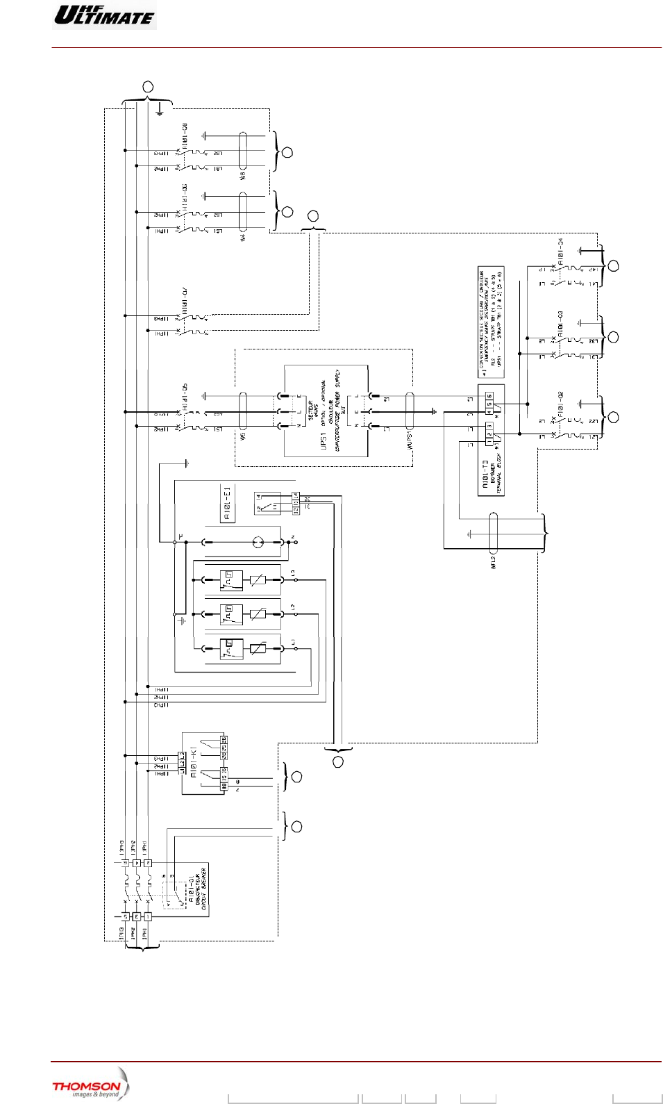
ARRIVEE SECTEUR SECOURU
EMERGENCY MAINS INPUT
32
4
576
8
910
1
Option
06/093(e-f)
ARRIVEE
SECTEUR
MAINS INPUT

Digital Liquid Cooled UHF
TV Equipment
Description / Test points / Location of units
9946 V1
45321648.01 104 A E preliminary 100 / 131
Numéro / Number Doc. Rev. Lan
g
u. 16/06/2006 Pa
g
e
Information contained is this document is confidential, is THOMSON property and cannot be disclosed in whatever form without prior written authorization of THOMSON.
3.12.2. Indicator lamps and message displays
♦ An orange indicator lamp on the mains monitoring relay K1 gives further information on the
incoming main supply as follows:
• Lit up : OK,
• Extinguished: absence or inversion of phases.
♦ E1 includes 4 surge arrestors “over voltage protection” ( 3 between Phases and Ground , the 4 th.
one between Neutral and Ground .When one surge arrestor is damaged, the light on the
corresponding arrestor is on : the plug-in module has to be replaced .
3.12.3. Test points and adjustment controls
The front panel of the Mains Distribution Panel does not have any test points or adjustment controls,
which can be used by the operator.
3.12.4. Protection and surveillance devices
Refer to the preceding section «operational description of the Mains Distribution Panel».
3.12.5. Connections and data transfer
The input connections to the mains distribution panel are used to determinate the incoming phase
voltage and earth.
The output connections are as following :
c Cables for feeding three phase supplies to the amplifier power supplies.
d Signal link cable allows to forward the surveillance status data of the main circuit breaker in the
Central Processing Unit via TB2 to roof interconnection J3.
e Signal link cables allows to forward the surveillance status data of mains (phase detector) in the
Central Processing Unit via TB2 to roof interconnection J3.
f Signal link cables allows to forward the surveillance status data of mains (over voltage) in the
Central Processing Unit via TB2 to roof interconnection J3.
g Cable for feeding single phase to the SIRIUS 1.
h Cable for feeding single phase to the SIRIUS 2.
i Cable for feeding single phase to the very low voltage power supply for the screen of the
control panel via the gestion rack
j NU
k Cable for feeding single phase to the very low voltage power supply for the Control Processor
Unit via the management rack
l Cable for feeding single phase to the exhaust fan on the roof.
NOTE : A connector TB1 allows to modify the Input mains configuration for feeding Sirius and
Screen of Control panel. This elements can be fed by an uninterruptible power supply
(UPS) via the circuit breaker Q5 (noted {option) or fed by the emergency mains input .
Both temperature informations ( input and output) are connected on terminal block TB2 .

Digital Liquid Cooled UHF
TV Equipment
Description / Test points / Location of units
9946 V1
45321648.01 104 A E preliminary 101 / 131
Numéro / Number Doc. Rev. Lan
g
u. 16/06/2006 Pa
g
e
Information contained is this document is confidential, is THOMSON property and cannot be disclosed in whatever form without prior written authorization of THOMSON.
3.12.6. Input power
The sole function of the Mains Distribution Panel is to re-distribute the mains input power and hence it
has no need of any other input power.
3.12.7. Cooling
The components of the Mains Distribution Panel are cooled by natural convection.
Digital Liquid Cooled UHF
TV Equipment
Description / Test points / Location of units
9946 V1
45321648.01 104 A E preliminary 102 / 131
Numéro / Number Doc. Rev. Lan
g
u. 16/06/2006 Pa
g
e
Information contained is this document is confidential, is THOMSON property and cannot be disclosed in whatever form without prior written authorization of THOMSON.
3.13. The multiplex card, 45324500
3.13.1. Outline
The multiplex card is the main connection distribution centre for the bay in which it is installed. It is the
central routing hub for input/output connections for status and command data circuits between:
♦ the Central Processing Unit on the one hand and the amplifiers, the amplifier power supplies and
the sensors (excluding the probes) on the other hand,
♦ the exciter cards and the amplifiers (AGC voltages),
♦ The UC card and the hydraulic cabinet.
3.13.2. Architecture
The multiplex card consists of a printed circuit card.
3.13.3. Operational description
-12V (B)
DC/DC
MUX/DEMUX
CPU-SUB ASSEMBIS DATA
DETECTION AND PRESENCE SIGNALS
FOR POWER SUPPIES TO
POWER AMPLIFIERS RF
AGC VOLTAGE
BLACK/WHITE VOLTAGE
POWER COOLING SYSTEM
LOOP PROTECTION SYSTEM
INTERFACE
LOOP PROTECTION SYSTEM
MUX/DEMUX
POWER SUPPLY
AMPLI.
INTERFACE
INTERFACE
UNITE CENTRALE
+ 5V_U
-12V (A)
04/021 (e)
+ 5V
Other
multiplex board
+ 5V_DC HYDRAULIC
CABINET
The main functions of the multiplex card are as follows:
♦ transmission of commands from the Central Processing Unit to the amplifiers,
♦ multiplexing and transmission to the Central Processing Unit, of data from:
• the amplifier power supplies,
• the amplifiers (via the amplifier power supplies),

Digital Liquid Cooled UHF
TV Equipment
Description / Test points / Location of units
9946 V1
45321648.01 104 A E preliminary 103 / 131
Numéro / Number Doc. Rev. Lan
g
u. 16/06/2006 Pa
g
e
Information contained is this document is confidential, is THOMSON property and cannot be disclosed in whatever form without prior written authorization of THOMSON.
• the sensors,
• the hydraulic cabinet.
The multiplex card is connected to the Central Processing Unit by a multiplexed bus; seven users
can be connected in parallel across this bus (the group of sensors + 5 PS/amplifiers +1 hydraulic
ports).
♦ transmission of AGC voltages from the power amplifiers to the exciter cards,
All AGC voltages from the amplifiers are applied to an "OR" logic gate. This "OR" gate on the
multiplex card extracts the largest of these AGC voltages. This voltage is used to control the power
delivered by the power amplifiers,
On transmitter with “separate channel” amplification, it excites an AGC vision separate loop and an
AGC sound loop.
♦ transmission of black/white voltage from video treatment card + Fl, from exciter plugged on the
antenna to the power amplifiers.
♦ detection and presence signals for the power supplies to the power amplifiers,
♦ switching on and switching off the amplifier power supplies in addition to switching on and off the
cooling system through a loop protection system,
♦ selection of equipment starting steps order: dependent on cooling (air or liquid),
♦ in case of several multiplex boards (2 or 3): the +5V_DC power supply redundancy is made by the
converter of one of the additional multiplex boards.
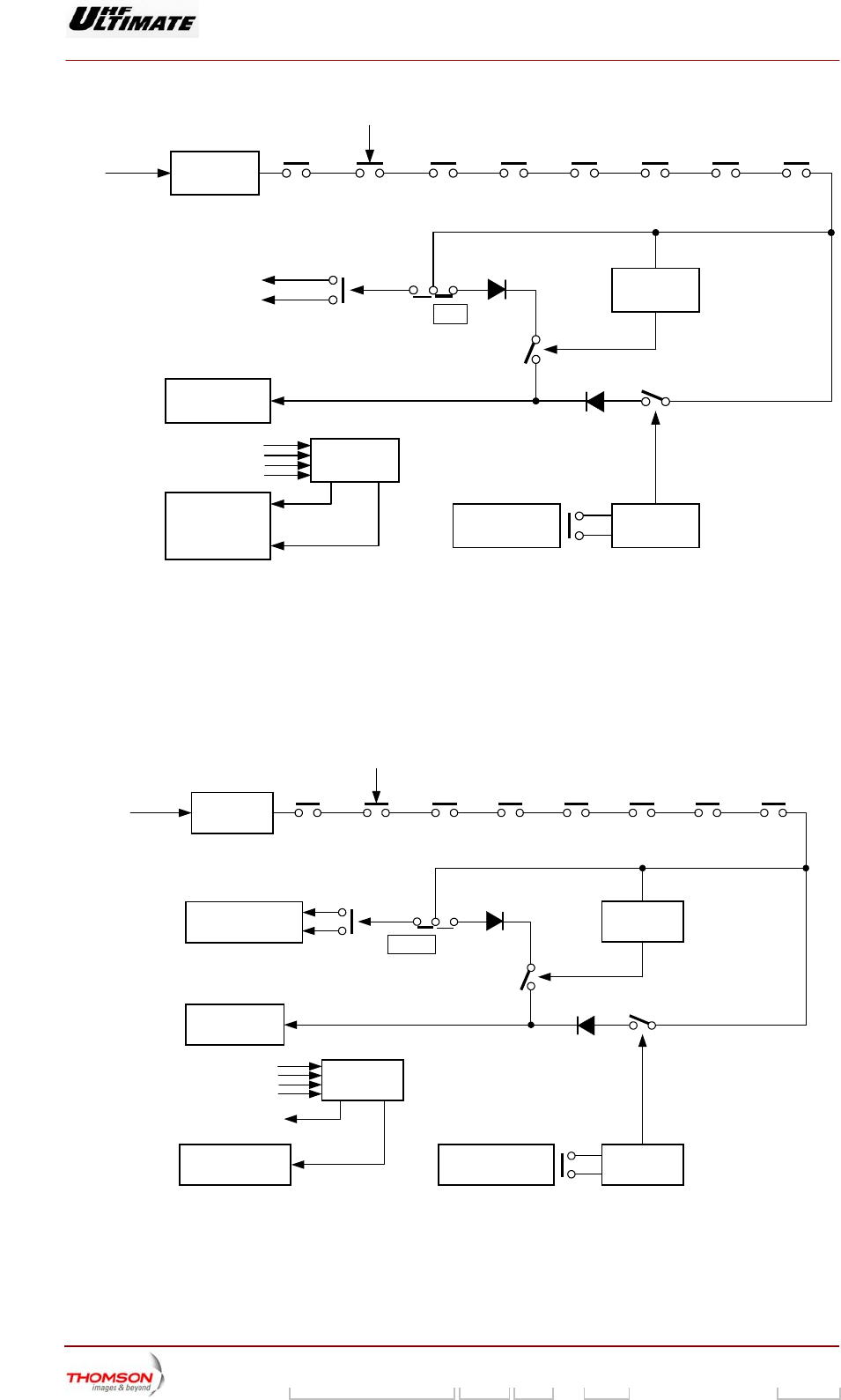
Switching on-air and switching off-air
The switching on and off of the amplifier power supplies and of the cooling system is controlled by the
position of the by-stable relay K1. The starting steps order depend on cooling.
♦ Air cooling:
• The closing of this contact by activating the "ON" command enables the transmission of the
+5 V voltage supply to the loop protection system and if this is closed the amplifier power
supplies are switched on. This ON condition is detected by an analogue "OR" circuit on the
multiplex card which triggers the start-up of the cooling system.
Digital Liquid Cooled UHF
TV Equipment
Description / Test points / Location of units
9946 V1
45321648.01 104 A E preliminary 104 / 131
Numéro / Number Doc. Rev. Lan
g
u. 16/06/2006 Pa
g
e
Information contained is this document is confidential, is THOMSON property and cannot be disclosed in whatever form without prior written authorization of THOMSON.
CURRENT
LIMIT
+ 5V_CHS SECU_STA SECU_ARM SECU_PRINCIP PRES_SECT TMPH SECT_VENTIL SECT_VENTIL_EX
RELAY
K1
ON
DELAY 1
AIRLIQUID
1 - POWER
SUPPLY ON
"OR"
GATE
(DIODES)
Cooling ON
(not used)
Mains presence
3 - POWER
SUPPLY ON
&
RF CONTROL(s)
to EMB
DELAY 2
2 - PRESSURE
SWITCH
SECURITY
04/017 (e)
Figure 23 : Air cooling system
♦ Liquid cooling:
• The closing of this contact by activating the “ON” command enables the transmission of the +5V
voltage supply to the loop protection system and if this is closed, the hydraulic pumps are
switched. Only when the hydraulic flow is correct, the power supplies are switched on.
CURRENT
LIMIT
+ 5V_CHS SECU_STA SECU_ARM SECU_PRINCIP PRES_SECT TMPH SECT_VENTIL SECT_VENTIL_EX
RELAY
K1
ON
DELAY 1
AIRLIQUID
3 - POWER
SUPPLY ON
"OR"
GATES
(DIODES)
Mains presence
4 - RF CONTROL(s)
to EMB DELAY 2
2 - FLOW METER
SECURITY
Hydraulic system
04/018 (e)
1 - COOLING ON
Hydraulic system
AIR COOLING
(no used)
Figure 24 : Liquid cooling system
Digital Liquid Cooled UHF
TV Equipment
Description / Test points / Location of units
9946 V1
45321648.01 104 A E preliminary 105 / 131
Numéro / Number Doc. Rev. Lan
g
u. 16/06/2006 Pa
g
e
Information contained is this document is confidential, is THOMSON property and cannot be disclosed in whatever form without prior written authorization of THOMSON.
The selection of starting steps order is configured via switches: S401, S402 and S403 on multiplex
board.
Cabinets which have more than 10 amplifiers have two multiplex cards as follows:
♦ one of them is associated with 8 amplifiers and the total protection system,
♦ the other is associated with the remaining amplifiers and its protection system only monitors the
station protection system while the other surveillance device contacts are short circuited by a strap.
♦ The opening of the contact on the by-stable relay K1 by activating the "OFF" command which
comes from the exciter/CPU interconnection card switches off the +5 V supply which controls the
optical relays (K4 to K10). The opening of these relays switches off the amplifier power supplies
and the cooling system.
Protection system
Each cabinet has its protection system; it consists of sensor contacts which are connected in series in
the multiplex card. The open circuiting of just one of these contacts is enough to open the relays which
control the mains feeds to the amplifier power supplies and the cooling system.
When the transmitter is started up and the cooling is switched off, the "cooling air pressure correct"
signal is simulated in order that the associated surveillance device does not prevent the switch-on of
the amplifier power supplies.
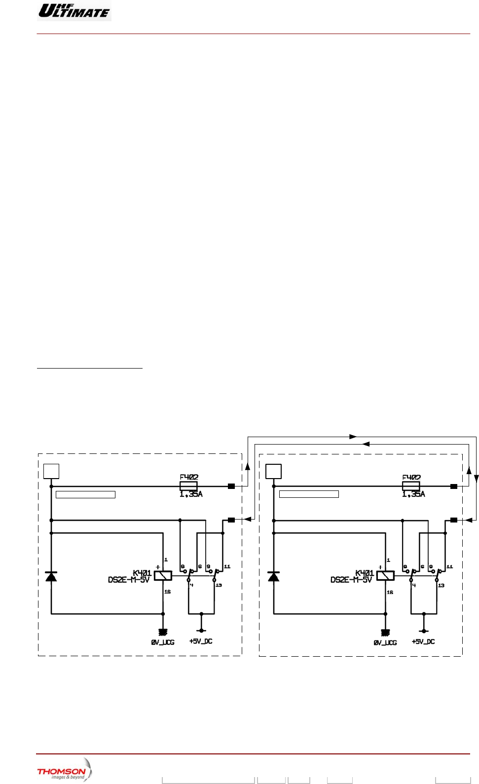
+5V_DC redundancy
This redundancy is available (whatever the defected converter) only with cabinet with 2 or 3 multiplex
boards.
In case of 3 multiplex boards, only one redundancy is possible.
With 2 multiplex boards:
In case of first DC/DC converter G1 failure:
♦ contact of relay K401 toggles,
♦ second converter G1 supplies system with +5V_via fuse F402.
G1
OUTPUT
INPUT
+ 5V
+5V
G1
OUTPUT
INPUT
+ 5V
+5V
04/019(e)
MULTIPLEX BOARD 1 MULTIPLEX BOARD 2
Digital Liquid Cooled UHF
TV Equipment
Description / Test points / Location of units
9946 V1
45321648.01 104 A E preliminary 106 / 131
Numéro / Number Doc. Rev. Lan
g
u. 16/06/2006 Pa
g
e
Information contained is this document is confidential, is THOMSON property and cannot be disclosed in whatever form without prior written authorization of THOMSON.
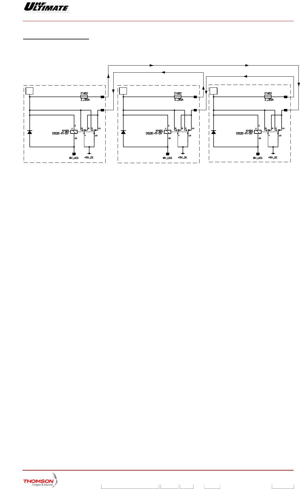
With 3 multiplex boards:
In case of converter G1 failure, the first converter takes over. In case of first converter G1 failure the
second converter takes over.
04/020 (e)
G1(1) OUTPUT
MULTIPLEX
BOARD 1 INPUT
+ 5V
+5V
G1(2) OUTPUT
MULTIPLEX
BOARD 2 INPUT
+ 5V
+5V
G1(3) OUTPUT
MULTIPLEX
BOARD 3 INPUT
+ 5V
+5V
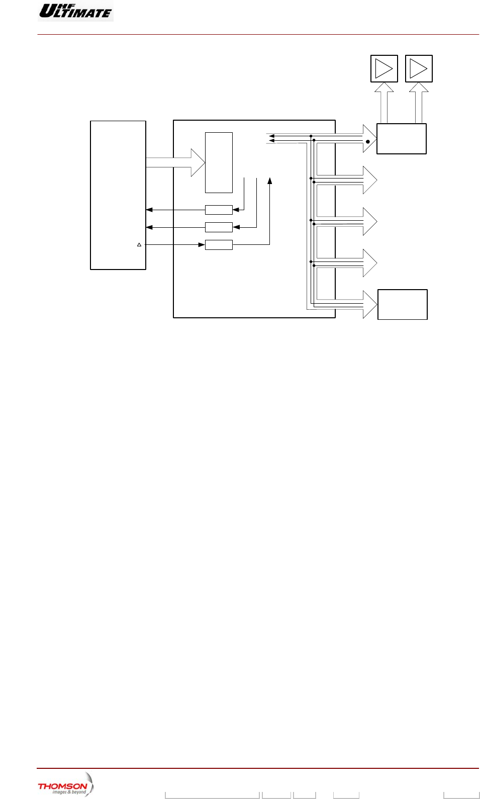
AGC voltages
The AGC voltages for each amplifier are fed to an OR gate before being sent to the exciters.
Power Supply voltage detection
As soon as the power supply voltage for the vision amplifiers has been detected, the signal PRE_ALI
(vision amplifiers power supply presence signal) is sent to the exciters.
As soon as the power supply voltage for the sound amplifiers has been detected, the signal PRE_ALS
(sound amplifiers power supply presence signal) is sent to the exciters.
Multiplexing/Demultiplexing of data signals
The name for a signal has the following format :
< Root > < Suffix > < Number >
♦ Each equipment unit is identified by a number. Numbers are also used to identify the equipment
unit internal parameters.
UB : Central Processing Unit ⇔ Multiplex board.
UE : Central Processing Unit ⇔ Exciter.
BA : Multiplex board ⇔ Power Supply – Amplifier.
UA : Central Processing Unit ⇔ Display Board.
♦ The root identifies the signal type:
AD : Address
DN : Data signal
DN – COM : Command data signal.
DN – INF : Logic read signal.
DN – ANA : Analogue read signal.
CS : Chip Select.
RW : Read – Write.
INI : Initialisation in progress signal.
Digital Liquid Cooled UHF
TV Equipment
Description / Test points / Location of units
9946 V1
45321648.01 104 A E preliminary 107 / 131
Numéro / Number Doc. Rev. Lan
g
u. 16/06/2006 Pa
g
e
Information contained is this document is confidential, is THOMSON property and cannot be disclosed in whatever form without prior written authorization of THOMSON.
POWER
SUPPLY
1
PAL
(2)
(1)
UC
( )
02/041b (e)
( )
(*)
HYDRAULIC
CABINET
(1) : AD_UB < 0…10 > is an 11-way multiplexed serial signal which defines a variable value
throughout the equipment,
signal RW_UB identifies a read or write cycle for the CPU board,
signal CS_UB (serial),
signal DN_INF_UC on 1 wire for reading a logic signal,
signal DN_INF_UC on 1 wire for reading an analogue signal,
(∆) : signal DN_COM_UB.
(2) : signal AD_BA < 0…3 > uses 4 wires for identifying an equipment unit parameter, i.e. a total of 16
parameters,
signal CS_BA selects an equipment unit (1 wire for each equipment unit).
(*) : signal DN_INF_UC on 1 wire for reading a logic signal,
(•) : signal DN_INF_UC on 1 wire for reading an analogue signal,
signal DN_COM_BA.
Read Cycle
The CPU sends signal AD_UB < 0…10 > and checks that the read cycle has started via signal
RW_UB ; it validates signal CS_UB before sending validation confirmation to the multiplex board.
The multiplex board decodes the number within the signal AD_UB < 0…10 > via the PAL unit and
generates the following signals:
♦ AD_BA < 0…3 > (identification of an equipment unit parameter),
♦ CS_BA (selection of equipment unit).
The address AD_BA < 0…3 > is sent to all the equipment units, but only the equipment unit selected
by the signal CS_BA will reply with a readout.

Digital Liquid Cooled UHF
TV Equipment
Description / Test points / Location of units
9946 V1
45321648.01 104 A E preliminary 108 / 131
Numéro / Number Doc. Rev. Lan
g
u. 16/06/2006 Pa
g
e
Information contained is this document is confidential, is THOMSON property and cannot be disclosed in whatever form without prior written authorization of THOMSON.
The selected equipment unit will simultaneously send both logic signal DN_ANA_BA and analogue
signal DN_ANA_BA corresponding to the number within address AD_BA < 0…3 >.
Each of these signals is sent along a single wire which is connected to all the equipment units via the
multiplex board; equipment units which have not been selected via the CS_BA signal will not return
any signal.
Signals DN_INF_UB and DN_ANA_UB are then sent to the CPU via the multiplex board. The CPU
reads the analogue signal or logic signal and then disables signal CS_UB in order to indicate the end
of the cycle.
Note : If a non-selected equipment unit exhibits a malfunction with regard either to signal DN_ANA_BA or
to signal DN_INF_BA there will be incorrect routing to the CPU of the signal from the equipment
unit selected by the CS_UB signal.
In order to determine the source of this problem, disconnect connectors J1 to J5 on the multiplex
board and check for normal signal transfer with the rest of the equipment; then re-connect the
connectors one after the other to identify which Power supply/Amplifier assembly is causing the
faulty communication.
Disconnect the two amplifiers from the identified assembly and reconnect the multiplex board
connector (J1 to J5).
♦ In the case of faulty communication, first replace the cable connecting the multiplex board to the
power supply and the power supply itself in order to identify the faulty component.
♦ In the case of correct communication, interchange the two amplifiers in order to identify the
faulty component.
Write Cycle
The CPU sends the signal AD_UB < 0…10 > to start the write cycle via signal RW_UB; it sends the
command signal via signal DN_COM_UB and validates signal CS_UB before sending validation
confirmation to the multiplex board.
The multiplex board transfers the status of signal DN_COM_UB to signal DN_COM_BA.
The multiplex board then decodes the number the signal AD_UB < 0…10 > via the PAL unit and
generates the following signals:
♦ AD_BA < 0…3 > (identification of an equipment unit parameter),
♦ CS_BA (selection of equipment unit),
♦ The CPU holds signal CS_UB for 10 ms to indicate the end of the write cycle while the multiplex
board disables signal CS_BA.
Digital Liquid Cooled UHF
TV Equipment
Description / Test points / Location of units
9946 V1
45321648.01 104 A E preliminary 109 / 131
Numéro / Number Doc. Rev. Lan
g
u. 16/06/2006 Pa
g
e
Information contained is this document is confidential, is THOMSON property and cannot be disclosed in whatever form without prior written authorization of THOMSON.
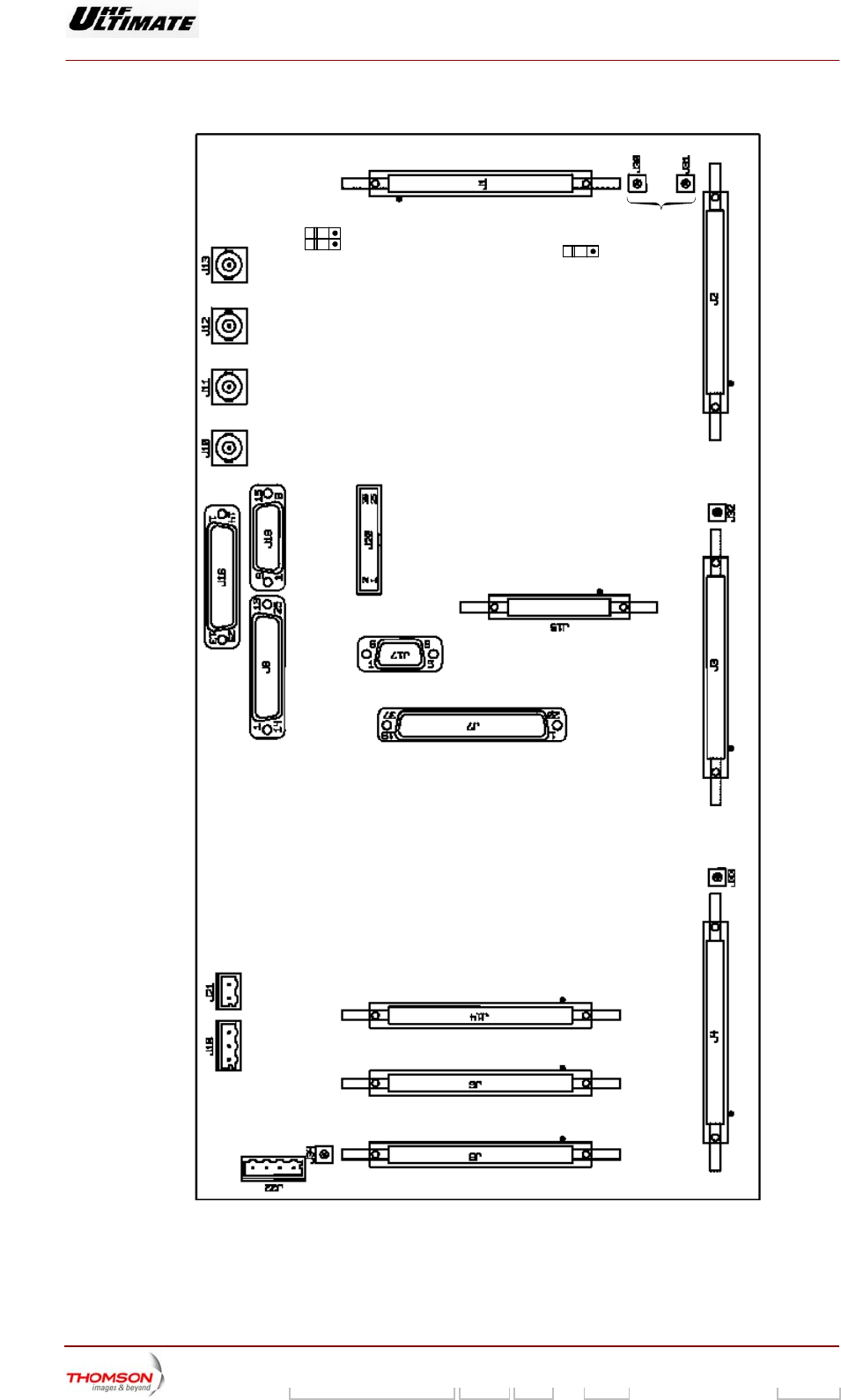
04/007 (e)
Amplifier
plug-in contacts
E/S UC
Non utilisé
Sensor
inputs
IO
external
systems
Sensor
inputs
I/O
other multiplex
board
I/O power supply 4 I/O power suply 3 I/O power supply 2
I/O power
supply 1
I/O
power
supply 5
I/O
CPU
Sound
AGC
input
Sound
AGC
output
Vision
AGC
input
Vision
AGC
output
Reserve
Non utilisé
LV
input
Card substitution
S402
Cooling system
start
Cooling system
start
S401
S403
Reserve
Reserve
Reserve
**
* Other multiplex card
Figure 25 - Location of connectors on multiplex card

Digital Liquid Cooled UHF
TV Equipment
Description / Test points / Location of units
9946 V1
45321648.01 104 A E preliminary 110 / 131
Numéro / Number Doc. Rev. Lan
g
u. 16/06/2006 Pa
g
e
Information contained is this document is confidential, is THOMSON property and cannot be disclosed in whatever form without prior written authorization of THOMSON.
3.13.4. Indicator lamps and message displays
If the internal +5 V from the internal regulator on the multiplex card is faulty or missing the following
indications are given:
♦ the green LED. "DS3" is extinguished,
♦ the message "UNKNOWN" is displayed in the "PSU n" message windows in the PCL "POWER
SUPPLY" window.
3.13.5. Protection and surveillance devices
The multiplex card has a monitoring circuit for its own internal power supply.
It has protection devices ahead of the -12 V/+5 V regulator as follows:
♦ F2: protects the -12 V supply from the exciter A power supply card,
♦ F3: protects the -12 V supply from the exciter B power supply card.
These fuses go open circuit in over-current conditions and reset automatically; they cannot be
changed on line.
3.13.6. Adjustment controls
The card has no adjustment controls.
ATTENTION : There are switches on the multiplex card to configure the transmitter and also to set up
certain operational parameters in relation to the amplifier power supplies. These
jumpers and switches are factory-set and should not be repositioned.
3.13.7. Connections and data transfer
The multiplex card has the following connectors:
♦ connectors J1 to J5 which function as follows:
• they connect the data exchange bus between the amplifier power supplies 1 to 5 on the one
hand and the exciter/CPU interconnection card on the other; these data consist of:
- amplifier power supply status data,
- status and command data regarding the power amplifiers,
• their input signals are as follows:
- on and off commands for the multiplex cards,
- AGC voltages,
- removal/re-insertion status signals from the amplifier cards,
• their output signals are as follows:
- presence data regarding the power amplifiers and their power supplies,
♦ connector J6 which functions as follows:
• It connects to the data exchange bus to the Central Processing Unit, via the exciter/CPU
interconnection card; the data exchanged are as follows:
- amplifier power supply status data,

Digital Liquid Cooled UHF
TV Equipment
Description / Test points / Location of units
9946 V1
45321648.01 104 A E preliminary 111 / 131
Numéro / Number Doc. Rev. Lan
g
u. 16/06/2006 Pa
g
e
Information contained is this document is confidential, is THOMSON property and cannot be disclosed in whatever form without prior written authorization of THOMSON.
- status and command data regarding the power amplifiers,
- sensor status data both from the sensors in the protection system and from various other
sensors.
• it terminates the -12 V/+5 V DC input power supply from the exciter/CPU interconnection card,
• it accepts the transmitter start and stop commands,
• its output signals are as follows:
- presence data regarding the power amplifiers and their power supplies,
- mains presence data from the Mains Distribution Panel,
♦ connector J14, which by being connected to connector J6 on another multiplex card allows the
Central Processing Unit to be connected to several multiplex cards in parallel,
♦ input connector J7, for status signals from sensors,
♦ connector J8, which sends additional status data from the sensors to the Central Processing Unit,
♦ connector J10, which accepts the Sound AGC voltage from another multiplex card (used on an
analogue transmitter with split channels),
♦ connector J11, which sends the Sound AGC voltage to the exciter cards (used on an analogue
transmitter with split channels),
♦ connector J12, which accepts the AGC voltage (specifically the vision AGC voltage on an analogue
transmitter with split channels) from another multiplex card,
♦ connector J13, which sends the AGC voltage (specifically the vision AGC voltage on an analogue
transmitter with split channels) to the exciter cards,
♦ connector J15:
• sends the cooling On command to the cooling system,
• and receives the signal quality status data from an external measuring device,
♦ connector J16, which accepts the switched DC status signals for extraction/insertion of the power
amplifiers,
♦ connector J17, which accepts certain other status signals from sensors; these signals have no
connection with the protection system.
3.13.8. Power input
The multiplex card is fed with -12 V DC from the exciter power supply card(s).
An internal voltage regulator provides the main power supply at -12 V/+5 V to the multiplex card.
The +5 V DC powers supply from the CPU power supply card is also used by some internal circuits.
These power supplies are fed from the exciter/CPU interconnection card via connector J6.
3.13.9. Cooling
The multiplex card is cooled by natural convection.

Digital Liquid Cooled UHF
TV Equipment
Description / Test points / Location of units
9946 V1
45321648.01 104 A E preliminary 112 / 131
Numéro / Number Doc. Rev. Lan
g
u. 16/06/2006 Pa
g
e
Information contained is this document is confidential, is THOMSON property and cannot be disclosed in whatever form without prior written authorization of THOMSON.
3.14. Coupling system
3.14.1. Outline
The purpose of the RF combiner is to add together the power signals from the RF power amplifiers.
An input unit splits the power signal from the exciter into signals, which are exactly matched in
amplitude and phase, and sends them to the amplifiers.
An F.I.C.S. (Full Isolated Coupling System patented by THALES) unit adds the powers signals
delivered by the amplifiers. The system has an isolating unit, which avoids mismatch problems when
one or more amplifiers fail.
3.14.2. Architecture
The F.I.C.S. unit consists of:
♦ a stage consisting of 3 dB couplers (one coupler per amplifier),
♦ one or two load circuits,
♦ two 4 to 16 way combiners (one way per amplifier),
♦ an output 3 dB coupler.
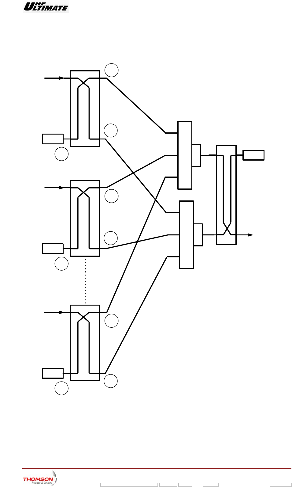
3.14.3. Operational description
At the output of each amplifier a 3 dB coupler produces the power signals which are exactly matched
in amplitude and with an aperiodic phase difference of 90° to two distribution modules (6 inputs - 1
output). These two modules are connected to another 3 dB coupler which recombines the power
signal and delivers it to the transmitter channel output.
Next figure describes the basic principle of the F.I.C.S. unit:
♦ the amplifiers are connected to the inputs of the 3 dB couplers,
♦ the outputs (a) from the 3 dB couplers are connected to the distribution module (A),
♦ the outputs (b) from the 3 dB couplers (which have a phase difference 90° with the (a) outputs) are
connected to the distribution module (B),
♦ outputs (c) from the 3 dB couplers are connected to the load circuit; each input of this unit
terminates in a set of four resistors which can dissipate 850 W.
In normal operation the signals applied to the inputs of the distribution modules are exactly matched in
amplitude and phase. Hence they add together completely. The output 3 dB coupler adds the signals
and sends the combined signal to the RF output.
When not operating normally (amplitude and/or phase mismatch or amplifier failure) the signal applied
to a distribution module input has the following three components:
♦ the component transmitted to the module output,
♦ the reflected component,
♦ the component applied to the other amplifier outputs.
Because of the aperiodic phase difference of 90° between the two distribution modules, the
components, which are reflected or transmitted to the amplifiers, are recombined in the load
terminations of the 3 dB input couplers.
The components transmitted to the module output recombine at the output of the 3 dB output coupler.
Hence in all operational circumstances the system gives absolute protection to the amplifiers even in
the case of the shut-down of one or several amplifiers.
Digital Liquid Cooled UHF
TV Equipment
Description / Test points / Location of units
9946 V1
45321648.01 104 A E preliminary 113 / 131
Numéro / Number Doc. Rev. Lan
g
u. 16/06/2006 Pa
g
e
Information contained is this document is confidential, is THOMSON property and cannot be disclosed in whatever form without prior written authorization of THOMSON.
The ratio of total power to transmitted power (ignoring system losses) is a function of the form : n2/ (n-
m) 2.
where «n» is the total of amplifiers and «m» is the number of faulty amplifiers.
Input 1
R.F. Signal
a
b
c
I
Input « n »
R.F. Signal
a
b
c
I
Input 2
R.F. Signal
a
b
c
I
Output
II
A
B
Combiner
3dB Coupler
3dB Coupler
98/331 (e)
Figure : FICS
3.14.4. Protection and surveillance devices
The RF coupling system does not need any particular internal protection or surveillance devices.

Digital Liquid Cooled UHF
TV Equipment
Description / Test points / Location of units
9946 V1
45321648.01 104 A E preliminary 114 / 131
Numéro / Number Doc. Rev. Lan
g
u. 16/06/2006 Pa
g
e
Information contained is this document is confidential, is THOMSON property and cannot be disclosed in whatever form without prior written authorization of THOMSON.
3.14.5. Adjustments
No adjustment controls are needed on the RF coupling system.
3.14.6. Connections and data transfer
The vision channel input splitter has the following connectors:
♦ an input connector for the exciter RF output signal,
♦ output connectors for the RF signals to the inputs of the RF power amplifiers.
The F.I.C.S. combiner has the following connectors:
♦ input connectors (one per amplifier) for the RF power amplifier outputs,
♦ output connectors for the co-axial cable connections to the load circuits (one per amplifier, plus one
for the F.I.C.S. output 3 dB coupler),
♦ a feeder output which feeds the RF signal to the filter assembly.
The load circuit input connectors are connected to resistor sets by co-axial cables.
3.14.7. Input power
The RF coupling system does not need any input power.
3.14.8. Cooling
The load circuits are mounted on a heat sink capable of dissipating the heat gain from the resistors.
The transmitter cooling system cools the heat sink itself. The transmitter cooling system cools the sink
itself.

Digital Liquid Cooled UHF
TV Equipment
Operating modes and Control modes
9946 V1
45321648.01 104 A E preliminary 115 / 131
Numéro / Number Doc. Rev. Lan
g
u. 16/06/2006 Pa
g
e
Information contained is this document is confidential, is THOMSON property and cannot be disclosed in whatever form without prior written authorization of THOMSON.
4. Operating modes and Control modes
4.1. SIRIUS initialisation
♦ When the SIRIUS is commissioned it must receive initialisation commands from the transmitter
CPU:
Some SIRIUS operational parameters which are in the CPU memory are transferred to the SIRIUS
by a command from the PCL (in maintenance mode).
Afterwards, the operator can change some of these parameters using the PCL.
4.2. Transmitter operating modes
The transmitter has the following modes of operation:
♦ Installation mode:
The transmitter assumes this mode when mains is first switched on or when the CPU card is
replaced. It consists of an initialisation procedure for the CPU card.
In this mode the control system sets the transmitter operational parameters and status conditions
to the default values; these values can be changed by the operator using the PCL.
The principal facilities available in this mode are as follows:
• polling,
• making entries in the log book,
• display of installation window.
The following important facilities are not available:
• processing of faults,
• command control system.
♦ Normal mode:
In this mode all operational facilities are available. Selecting maintenance commands on the exciter
cards or adjusting/changing parameters on the PCL (alarm threshold, power reduction, etc.) are not
available.
♦ Maintenance mode:
In this mode the fault analysis and processing system is not available. Operations and commands
which are not available in normal mode can be carried out by the operator.
4.3. On-air mode
This mode can be activated automatically or manually as follows:
♦ when automatic switch to air mode has been selected:
• the transmitter can only go on-air if an input signal is present,
• if no input signal is present the transmitter will be switched off air by removing the amplifier
power supply feed.

Digital Liquid Cooled UHF
TV Equipment
Operating modes and Control modes
9946 V1
45321648.01 104 A E preliminary 116 / 131
Numéro / Number Doc. Rev. Lan
g
u. 16/06/2006 Pa
g
e
Information contained is this document is confidential, is THOMSON property and cannot be disclosed in whatever form without prior written authorization of THOMSON.
♦ when the manual on-air mode is selected, switching to air and switching off-air are available as
specific operator commands; when the transmitter has been switched on all power supplies are on
irrespective of the presence or not of video at the input.
4.4. Different operational states of exciter
(Dual drive version)
An exciter will be in one of the following states :
♦ selected and switched to the RF power amplifiers and hence to air (to antenna); this is the normal
operational state for the transmitter assuming that an automatic changeover has not taken place,
♦ selected but not switched to air; this is the case for an exciter which has been selected but there
has been an automatic exciter changeover,
♦ in reserve; this is the case for an exciter which has not been selected and is not switched to air,
♦ not selected but switched to air; this is the case for the reserve exciter after there has been an
automatic exciter changeover.
In all of these states the exciter can be operational or not.
The operational states of the exciters can be checked in the "EXCITER 1" window on the PCL.
4.5. The two exciter changeover modes
(Dual drive version)
The changeover switch between the two exciters can take place automatically or under manual
control.
♦ In the automatic changeover mode the facilities for an automatic switch between the two exciters
(A → B or B → A) if a fault appears on the selected exciter channel have been enabled; in this
mode it is possible to initiate the changeover switch manually.
In the automatic changeover mode the identity of the selected exciter is not changed; this is not the
case with manual changeover.
♦ In the manual changeover the switch can only take place as a result of a command from a user
interface (PCL or remote user interface).
The manual changeover changes the identity of the selected exciter.
The changeover mode which has been selected can be monitored and changed in the "EXCITER 1"
window on the PCL.
At any given time an automatic changeover between the exciters may have taken place, may have not
taken place or may be impossible. The "EXCITER 1" window on the PCL shows which of these three
is the case.
If an automatic changeover has taken place the On-Air exciter has not been selected and hence a
subsequent automatic changeover is impossible. Another automatic changeover can take place if:
♦ a manual changeover has been commanded, or,
♦ a transmitter "RESET" operation is carried out. In this instance care must be exercised because the
records of all cleared faults as well as their consequences to the system will be erased; all
selections effected on the PCL will also be erased.
Digital Liquid Cooled UHF
TV Equipment
Operating modes and Control modes
9946 V1
45321648.01 104 A E preliminary 117 / 131
Numéro / Number Doc. Rev. Lan
g
u. 16/06/2006 Pa
g
e
Information contained is this document is confidential, is THOMSON property and cannot be disclosed in whatever form without prior written authorization of THOMSON.
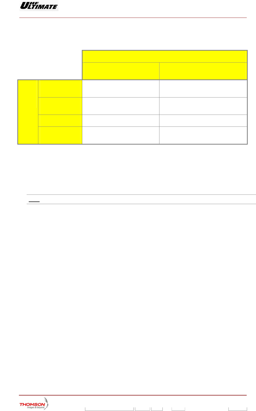
The following table illustrates how the status of an exciter changes after both a manual changeover
and an automatic changeover:
STATUS OF EXCITER AFTER A CHANGEOVER
MANUAL CHANGEOVER (SELECTED
EXCITER IS CHANGED) AUTOMATIC CHANGEOVER (FAULT ON
SELECTED EXCITER CHANNEL)
SELECTED AND ON-
AIR
Reserve Selected and off-air
SELECTED AND OFF-
AIR
Reserve No change
RESERVE Selected and on-air Not selected and on-air
INITIAL
STATE
OF
EXCITER
NOT SELECTED AND
ON-AIR
Selected and on-air No change
4.6. Transmitter control modes
The transmitter can be controlled either (a) in local control mode from a Local Control Panel (PCL), or
(b) in remote control mode from a remote user interface:
♦ in local control mode, only commands from the PCL will be recognised by the system. The remote
user interface is not enabled.
Note : Commands from the PCL can be locked (disabled) by using a password.
♦ in remote control mode, only commands from the remote user interface will be recognised by the
system. The PCL interface is not enabled.
Digital Liquid Cooled UHF
TV Equipment
Internal and external connections
9946 V1
45321648.01 104 A E preliminary 118 / 131
Numéro / Number Doc. Rev. Lan
g
u. 16/06/2006 Pa
g
e
Information contained is this document is confidential, is THOMSON property and cannot be disclosed in whatever form without prior written authorization of THOMSON.
5. Internal and external connections
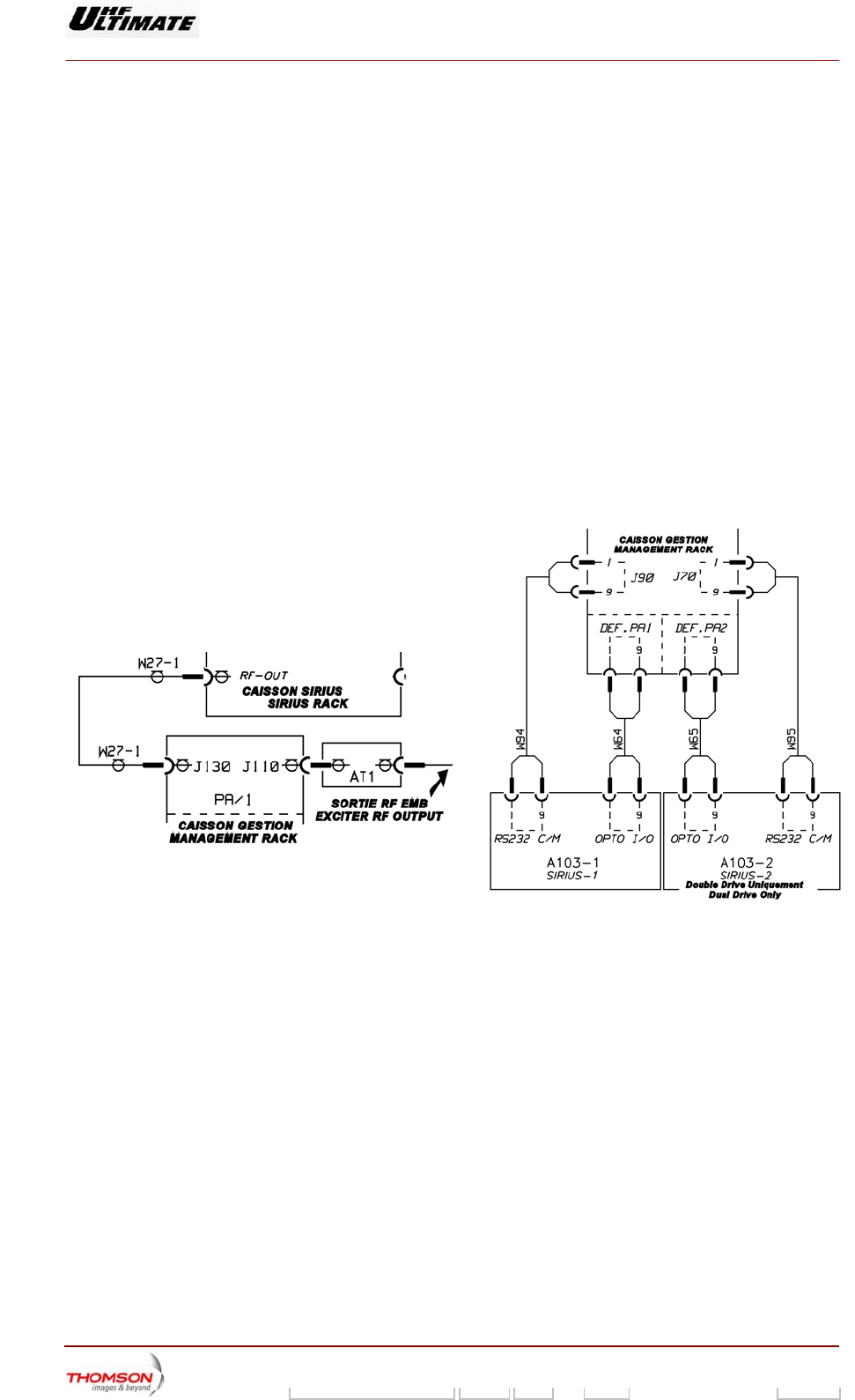
5.1. Transmitter inter-unit connections
5.1.1. Cabinet inter-unit connections
5.1.1.1. Exciter Sub-assemblies links
(see RF links and signal links diagrams)
The cards of the set EMB are distributed between the following boxes:
♦ Box SIRIUS including mainly the treatment of the signal and its RF conversion,
♦ The box of Management including An amplification function for the RF signal
All the data exchanged between the subsets EMB of these boxes, pass in transit opposite back.
There are two types of connection:
RF links
Signal links
Figure 26 : RF links
Figure 27 : Signal links
All the data exchanged between the subsets of the box SIRIUS and the outside (Signals MPEG,
10MHz, 1PPS, FdD ..), also pass in transit opposite back of this one.
5.1.1.2. Connections between CPU and exciter
(Refer to links interconnection diagrams).
The CPU card is plugged into the digital TX interconnection card and it exchanges the following with
the exciter via the serial link RS232:
♦ command signals,
♦ status data.
In the Double Drive version, the digital TX interconnection card is connected to each of the SIRIUS
rack in rear panel of the frame.

Digital Liquid Cooled UHF
TV Equipment
Internal and external connections
9946 V1
45321648.01 104 A E preliminary 119 / 131
Numéro / Number Doc. Rev. Lan
g
u. 16/06/2006 Pa
g
e
Information contained is this document is confidential, is THOMSON property and cannot be disclosed in whatever form without prior written authorization of THOMSON.
5.1.1.3. Connections for switched dc and analogue signals within the transmitter
(Refer to signal links diagram).
The transmitter sub-units have switched DC and analogue interconnections for status, display and
command data with the CPU and the multiplex card.
All data exchanges between the CPU and the transmitter sub-units pass through the digital TX
interconnection card.
All data exchanges between the CPU and the transmitter sub-units other than the exciter cards and
the user interfaces also pass through the multiplex card.
Data to and from the amplifiers pass through the amplifier power supplies.
For cabinets in transmitters with power outputs greater than 4 kW, connections between the second
multiplex card and the CPU are made via the first multiplex card.
5.1.1.4. RF connections
(Refer to RF links diagram).
Coaxial cables and feeders are used for the RF signal connections between the various transmitter
sub-units.
5.1.2. Connections between Central Processing Unit and user interfaces
Connections between Central Processing Unit and user interfaces
Various types of connection are used for data exchanges between the User Interfaces and the Central
Processing Unit:
♦ PCL connections (via interconnection card):
• RS 232 serial link using JBUS protocol,
• switched DC connections,
• analogue connections.
♦ serial link to a remote user interface (via interconnection card): RS 232 serial link using THALES
protocol,
♦ hard wired connections to a user interface (via interconnection card): Remote control and remote
indications conform to the IEC 864-1 standard,
♦ connection with log book terminal: RS 232 serial link.
5.1.3. Connections between cabinet and filter unit
The connections between the cabinet and the band filter consist only of RF connections for which co-
axial cables and feeders are used.
Digital Liquid Cooled UHF
TV Equipment
Internal and external connections
9946 V1
45321648.01 104 A E preliminary 120 / 131
Numéro / Number Doc. Rev. Lan
g
u. 16/06/2006 Pa
g
e
Information contained is this document is confidential, is THOMSON property and cannot be disclosed in whatever form without prior written authorization of THOMSON.
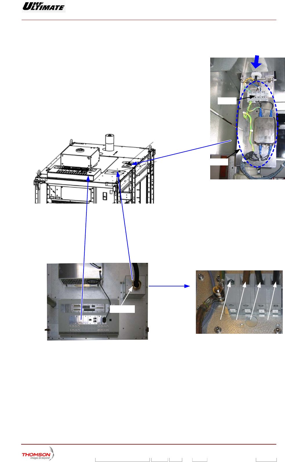
5.2. Location of principal connectors
These diagrams show the positions of the main transmitter connections.
FL2
TB
09-xx3A
(e)
09-xx2A (e)
06/115(e)
L1L2L3N
FL2
Arrivée secteur secouru
Emergency mains input
FL1
Arrivée secteur
Mains input
Capot
Digital Liquid Cooled UHF
TV Equipment
Internal and external connections
9946 V1
45321648.01 104 A E preliminary 121 / 131
Numéro / Number Doc. Rev. Lan
g
u. 16/06/2006 Pa
g
e
Information contained is this document is confidential, is THOMSON property and cannot be disclosed in whatever form without prior written authorization of THOMSON.
MAINS
INPUT
LIQUID
INDOOR
EMERGENCY
MAINS INPUT
(Optional)
TB1
LIQUID
OUTDOOR
GROUND - M10
NEUTRE
L3 L2 L1
RF INPUT
EV3
J6 TB1
SIRIUS-2
A103-2 LAN2
SIRIUS-1
A103-1 LAN2
GESTION RACK
A130 LAN
5J1
J1
J8J6
J3 J5 J7
J2 J4
B
J2
J1
J8J6
J3 J5 J7
J4
A
J5 TB2 J9BJ1
06/079b(e)
Figure 28 : Top of cabinet B860 and Sockets supports
(safety extra low voltage)
Digital Liquid Cooled UHF
TV Equipment
Internal and external connections
9946 V1
45321648.01 104 A E preliminary 122 / 131
Numéro / Number Doc. Rev. Lan
g
u. 16/06/2006 Pa
g
e
Information contained is this document is confidential, is THOMSON property and cannot be disclosed in whatever form without prior written authorization of THOMSON.
♦ Connexion toit de Baie/Roof Inter connection
A106-TB1
1
2
Défaut Température Sortie/Output temperature Fault
3
4
Défaut Refroidissement Externe/External Cooling Fault
5
6
Défaut Ventilation Externe Filtre RF/Cooling RF Filter Fault
7
8
Défaut Ventilation Externe DX/Cooling DX Faults
9
10
Défaut Débit/Flow Fault
11
12
Défaut Température Entrée/Input Température Fault
13
14
Défaut Filtre à Air/Air Filter Fault – Alarme Débit/Flow Alarm
15
16
Non Connecté/Not Connected
A106-TB2
1 Non Connecté/Not Connected
3 Non Connecté/Not Connected
2
4
Info Marche/On Marche
A106-J..
A106-J1 Refroidissement externe/External Cooling
A106-J5 Interconnexion brassage Txn-1/Interconnetion Board Txn-1
A106-J6 Interconnexion brassage Txn+1/Interconnetion Board Txn+1
Ethernet supervision / Ethernet supervision
A130 LAN Ethernet Caisson gestion / Gestion rack
A103-1 LAN2 Ethernet Sirius 1
A103-2 LAN2 Ethernet Sirius 2
Digital Liquid Cooled UHF
TV Equipment
Internal and external connections
9946 V1
45321648.01 104 A E preliminary 123 / 131
Numéro / Number Doc. Rev. Lan
g
u. 16/06/2006 Pa
g
e
Information contained is this document is confidential, is THOMSON property and cannot be disclosed in whatever form without prior written authorization of THOMSON.
Entrée Signaux / Input Signal
J1A Entrée Signal 1 / Signal 1 Input
J2A Entrée 10 MHz/10 MHz Input
J3A Entrée 1 P.P.S/1 P.P.S Input
J5A Entrée Signal 2 / Signal 2 Input
J8A
SIRIUS 1
Entrée GPS / GPS Input
J2B Entrée 10 MHz/10 MHz Input
J3B Entrée 1 P.P.S/1 P.P.S Input
J8B
SIRIUS 2
Entrée GPS / GPS Input
Digital Liquid Cooled UHF
TV Equipment
Internal and external connections
9946 V1
45321648.01 104 A E preliminary 124 / 131
Numéro / Number Doc. Rev. Lan
g
u. 16/06/2006 Pa
g
e
Information contained is this document is confidential, is THOMSON property and cannot be disclosed in whatever form without prior written authorization of THOMSON.
A130
Caisson Gestion
Gestion Rack
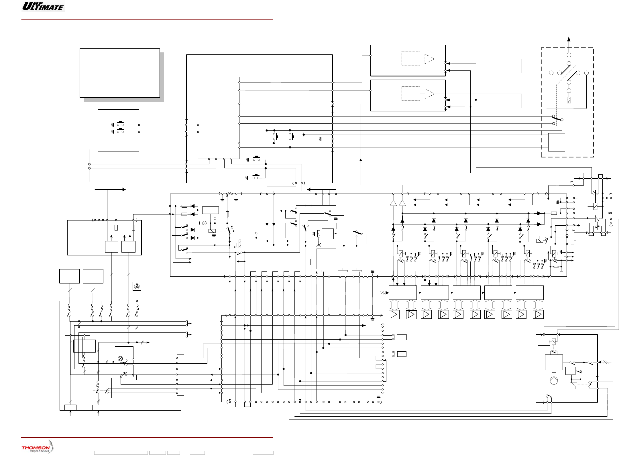
Schéma de démarrage
Starting Diagram
5,2 kW RMS MEDIAFLO
Double Drive, LIQUIDE
SIRIUS
45-46 J6
31-32 J6
page 1/1
20J6
S 301 ON
CARTE AFFICHEUR
DISPLAY BOARD
OFF
S 302
21J6
A15
PRES_HPA_PSU
J20 B4
J90
J30
5
6
7
1
2
4
3
J1
2
3
2324
D1 C1 B9
J6 B10
+5VOLTS_U_P
+12VOLTS_U_P
J20 B15
J20 A15
J20 B10
J6 A23
CARTE GESTION
CPU
J20 D3
INTERCONNEXIONS Equipement Numérique
Digital Equipment INTERCONNECTIONS
AR-ARM-UB
MA-ARM-UB
SW4 SW5
J20 D4
2
Vcc
GND
E1
E2
CR_POS_RLA
CR_POS_RLB
+5VOLTS_U_P
+12VOLTS_U_P
1
2
C
GND
COM_RLA
COM_RLB
Relais RF
RF Relay
06/91C (e-f)
Vers commande
ventilation externe
To external cooling
command
REG
-12V/+5V
43
48 45
J2 43
48 45
J3 43
48 45
J4 43
48 45
J5
25
26
J15
Alarme
débit
pour info
Tempo 5s
K200
5V-DC
Arrêt Marche
24 23
J6
40
34
21 22
161514131210987643
21J7
S700
S701
S702
S703
S704
S705
S706
S707
S708
S709
S710
S711
S712
S713
S714
22
31
15
22
31
15
22
31
15
22
31
15
3
12
S3
CR19
CR20
CR190
CR191
S7
S14
S8
S15
S9
S16
S12
S17
S13
S18
41
J14
24 23
24 J6
23 J6
31 32
31 J6
32 J6
41 40
45 46
45 J6
46 J6
5V-DC
10k
F2
F3
DS3
F1
TP1
K4 K5 K6 K7 K8
CR15 CR16 CR17 CR18 CR21
CR10 CR11 CR12 CR13 CR14
34-35
J14
7 8
36
35
37
J7
3
2
S11
S10
3
2
19 20
18
17
Défaut
Ventil.
Réseau
Charge
Défaut
Température
Entrée
31-32 J14
45-46 J14
Eau Air
Eau
Air
S402
S401
5
F402
K401
J19 J21
DEFAUT
2312
24V_AR
2
S2
S100
S101
TP3
5V-U
41 J6
40 J6
F4
TB2
J1
34
36
35
37
11
2 J2
31-32
45-46
Alimentation
SIRIUS
Driver A
Alimentation
SIRIUS
Driver B
+5V +12V
J1
2
3
+
-
A101
PLATINE
ENERGIE
ENERGY PANEL
PS1 à/to PS5
1
3
EMB
SIRIUS 1
(Marche TX)
(TX On)
EV3
Prise TC
sur le toit
TC connector
on the roof
Extracteur d’air
Exhaust fan
PS1
(A)
PS2
(B)
-12V_B_P
-12V_A_P
J4
+24V +12V
25-26-48 49
25 26 48 49
Provient de J4 de A130
Vers de J6 de A133
F5F3
19 20
16151413121110876
5
4321
J2 37
161514131211108765 94321
J1
9
1
2
3
4
5
6
7
8
9
10
11
12
13
15
16
14
TB1
J3
7
8
5
6
(*)
sécurité
Station
A106
ROOF INTERCONNECTION
(*): 9-10 de X11 du coffret hydraulique, Sécurité permutateur RF
3
4
EPLD
37
Alarme débit
Flow alarme
SL4
17 18 21 22
19 20 37
18 21 22
K9
Info.
Marche
K10
3
5
K2 A2
1 J2
4
J15
26
J2
37
35
A106
ROOF
4
26
26
25
213
Défaut débit
Flow fault
SL3
F
FCde
pompe
Pump cde
K4-1
21
On/off pompe
Pump on/off
S.G
DJ.
SECTEUR
MAINS
CENTRALE HYDRAULIQUE
HYDRAULIC CENTRAL
Défaut Pompe
Pump fault
65
K41
QS1
Q7
Alim
24V DC 3
4
X11
X11
X11
24V DC
17
18
19
20
22
21
Pompe
Pump
40
J4
J4
SW3 OFF
SW2 ON
J7
20
21
Sortie RF
RF Output
Carte
TX
RF-OUT
EMB
SIRIUS 2 Carte
TX
RF-OUT
PA_1
PA_2
RS232 C/M
RS232 C/M
J70
A130
CAISSON GESTION
GESTION RACK
J20
J19
RX_UE_A TX_UE_A
RX_UE_B TX_UE_B
25
28
TB2
K1 PHASE
DETECTION
OK
Q7
Q2
3 phases
3
4
1
2
SECTEUR
MAINS
FL2
SECTEUR PERMANENT
EMERGENCY MAINS
Q1-1
Q1
TB1
Q8
2/5
J1
Sécurité
Armoire
FL1
37PTS
10PTS
A133
CARTE DE BRASSAGE
MULTIPLEX BOARD
33
33
24V_AR
33 43
J4
CTRL MUTE
2
1
I/O 2
+ 24V
2
1
I/O 2
+ 24V
CTRL MUTE
CTRL MUTE
ALIMENTATION
2
POWER SUPPLY
AMPLI 3 AMPLI 4
ALIMENTATION
3
POWER SUPPLY
AMPLI 5 AMPLI 6
ALIMENTATION
4
POWER SUPPLY
AMPLI 7 AMPLI 8
ALIMENTATION
5
POWER SUPPLY
AMPLI 9 AMPLI 10
AMPLI 1
ALIMENTATION
1
POWER SUPPLY
AMPLI 2
18
15
9
7
8
10
9
1/4
Q6
Q5
UPS Onduleur
Option
Optionnal
3/6
Q4
Q3
Connexion secteur secouru
Emergency mains distribution
FL2: 1-2 et / and 4-5
UPS: 3-2 et / and 6-5
ST1
Temp sortie
Output temp.
Temp entrée
Input temp.
ST2
10
43
48 45
J1
22
31
15
Vers / To
33 J7
1 3
S20
De / From
3 J15
37
L
K2
K1
L
De / From
3 J2
25
J7
25
Vers / To
25 J2
5V-DC
Interlock Voltage
Tension chaîne de Sécurité
L
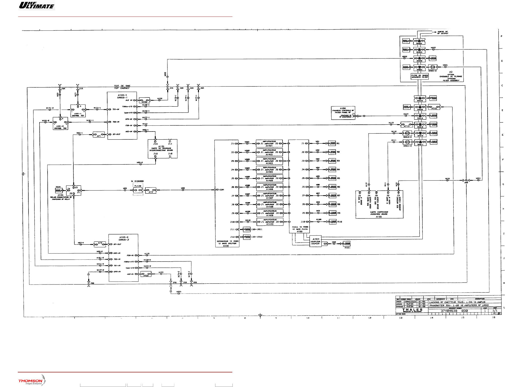
Digital Liquid Cooled UHF
TV Equipment
Internal and external connections
9946 V1
45321648.01 104 A E preliminary 125 / 131
Numéro / Number Doc. Rev. Lan
g
u. 16/06/2006 Pa
g
e
Information contained is this document is confidential, is THOMSON property and cannot be disclosed in whatever form without prior written authorization of THOMSON.
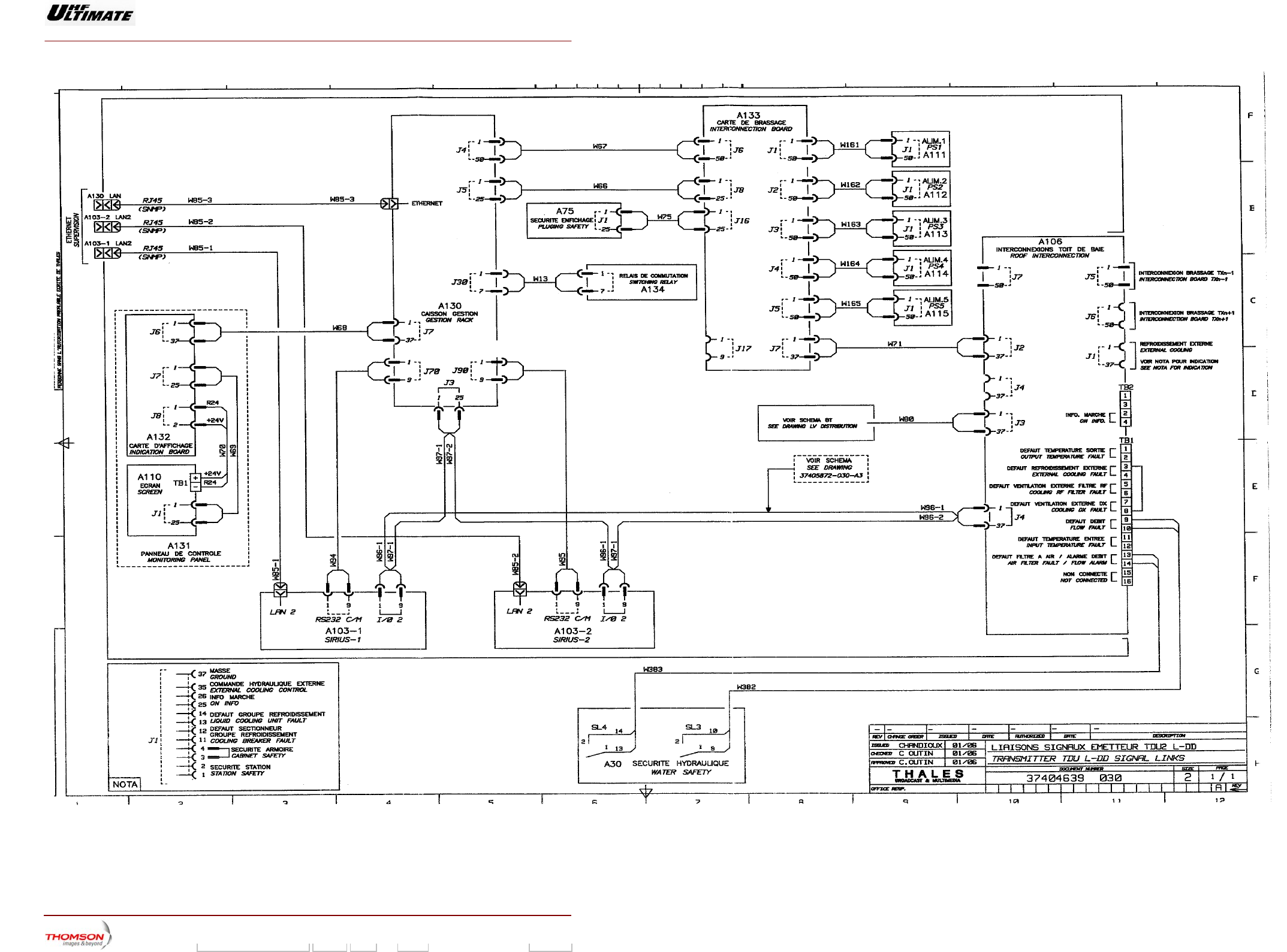
Digital Liquid Cooled UHF
TV Equipment
Internal and external connections
9946 V1
45321648.01 104 A E preliminary 126 / 131
Numéro / Number Doc. Rev. Lan
g
u. 16/06/2006 Pa
g
e
Information contained is this document is confidential, is THOMSON property and cannot be disclosed in whatever form without prior written authorization of THOMSON.
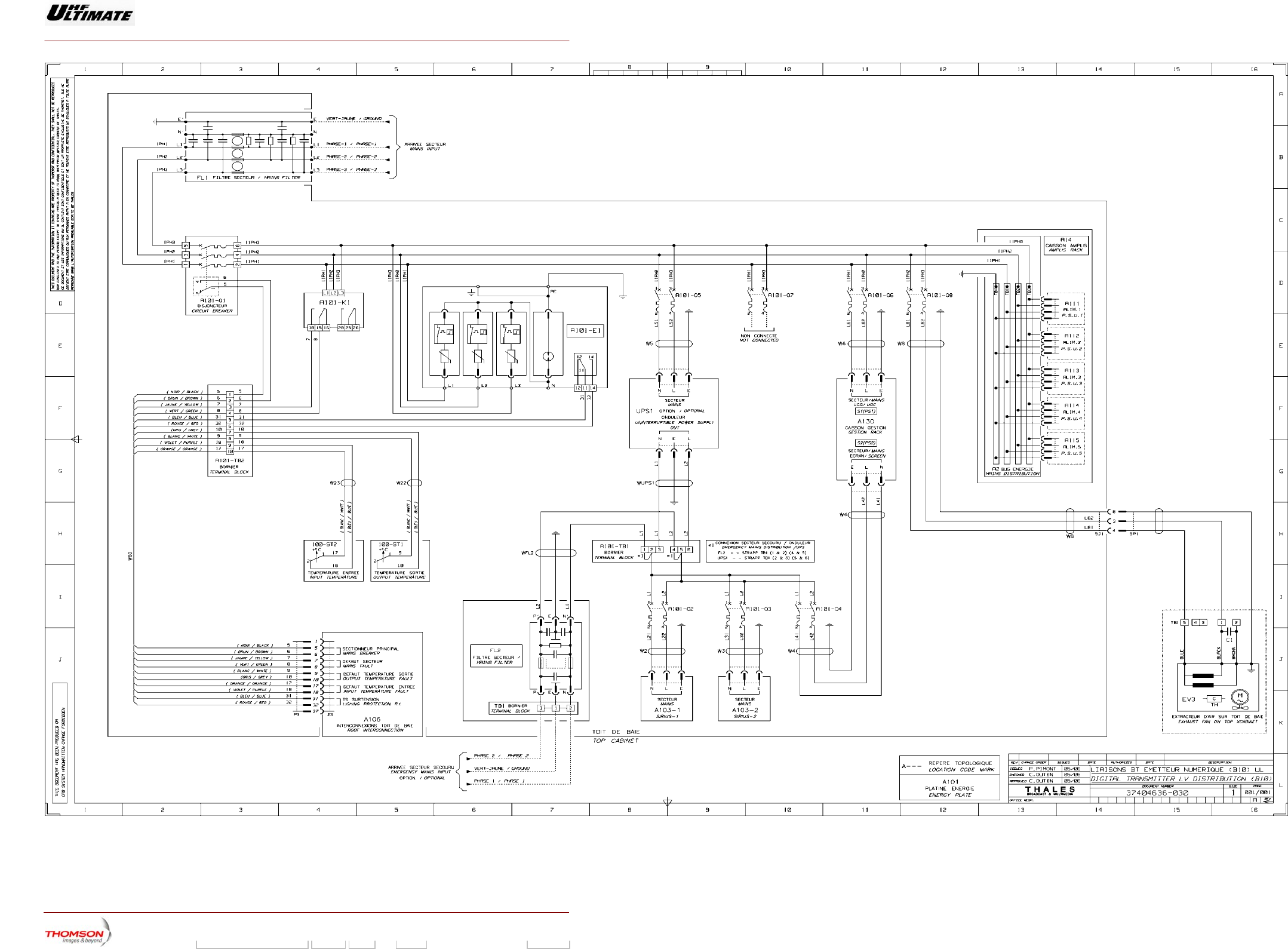
Digital Liquid Cooled UHF
TV Equipment
Internal and external connections
9946 V1
45321648.01 104 A E preliminary 127 / 131
Numéro / Number Doc. Rev. Lan
g
u. 16/06/2006 Pa
g
e
Information contained is this document is confidential, is THOMSON property and cannot be disclosed in whatever form without prior written authorization of THOMSON.