Thomson Broadcast and Multimedia ULT-1K10K2 UHF Digital transmitter, for use with MediaFlo User Manual PREIMPAP
Thomson Broadcast & Multimedia, Inc. UHF Digital transmitter, for use with MediaFlo PREIMPAP
Contents
User Manual part 2
Digital Liquid Cooled UHF
TV Equipment
Exploitation
Information contained is this document is confidential, is THOMSON property and cannot be disclosed in whatever form without prior written authorization of THOMSON.
1.12.2. Access to logbook
to a terminal
♦ continuously in real time or,
The operation is controlled from the "LOGBOOK" window and is only possible if maintenance mode
if the PCL is unlocked, i.e. enabled.
This procedure controls the facilities for sending a list of the various operational events
connected to the CPU. These data can be sent :
♦ when requested by the operator.
has been selected and
ACTION RESULT
Having selected the
"LOGBOOK" window indicates the method of sending data currently
selected.
♦ The "TRACE ON"/"TRACE OFF" control keys
♦ «TRACE ACTIVE» : sends the data in real time.
: sends the data after
operator request.
♦ «TRACE INHIBEE»
To chang
method of s
data:
ON" key or the ♦ The "TRACE ON"/"TRACE OFF" control keys
indicates the new method of sending the data.
e the
ending
♦ Press on the "TRACE
"TRACE OFF" key.
Sends the data a
operator re
ing selected "TRACE OFF":
ALL",
• Press on the "PAGE DOWN" key.
♦ Sends data on all operational events.
♦ Sends data on the 20 operational events previous
to the last events listed in the logbook.
♦ Sends data on the 20 operational events which
follow on from the last events listed in the
logbook.
fter
quest.
♦ Hav
• Press "DISPLAY
• Press on the "PAGE UP" key,
9932 V2
45321648.01 108 B E Checked 39 / 192
Numéro / Number Doc. Rev. Lan
g
u. 27/06/2006 Pa
g
e
Digital Liquid Cooled UHF
TV Equipment
Use of commands and description of indicators
Information contained is this document is confidential, is THOMSON property and cannot be disclosed in whatever form without prior written authorization of THOMSON.
2. Use of commands and description of indicators
2.1.
2.1.1.
The vario e Local Control Panel (PCL) provide the operator with the
follow :
♦ Trans
♦ Comm l state of the system, and commands to select the various
NOTE : The following windows are not available with an ATSC transmitter:
♦ SFN delay
♦ Modulation configuration
♦ Modulator status
♦ MIP data
♦ Modulator input setting
There are used in DVB-T transmitters only.
Ergonomics of screens
♦ Ergonomics of control keys :
• Text of browsing keys is yellow on blue background
Use and description of control panel screens
Outline
us windows displayed on th
ing
mitter status data,
ands to change the operationa
windows.
• Text of changing and confirming keys is black on
white background
♦ Ergonomics of message and information :
• Unmodifiable message is black on cyan blue
background
• Modifiable message is cyan blue on black
background
9932 V2
45321648.01 108 B E Checked 40 / 192
Numéro / Number Doc. Rev. Lan
g
u. 27/06/2006 Pa
g
e
Digital Liquid Cooled UHF
TV Equipment
Use of commands and description of indicators
Information contained is this document is confidential, is THOMSON property and cannot be disclosed in whatever form without prior written authorization of THOMSON.
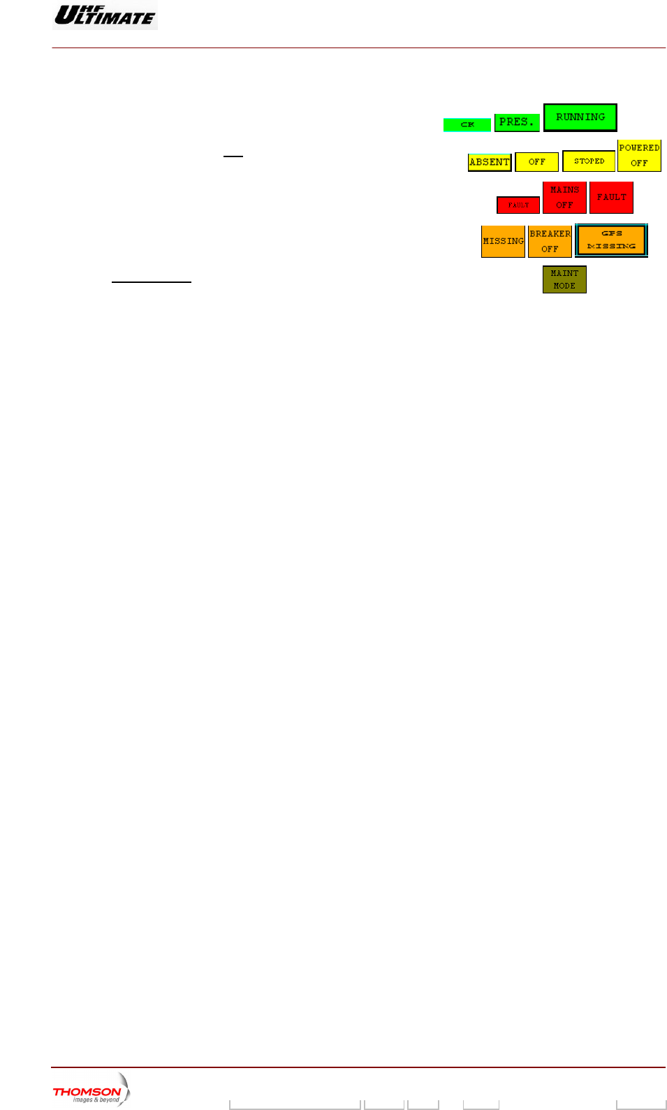
• Modifiable information is black on green, red, orange, yellow background
ckground - Normal state is on green ba
- bnormal state Abut without default is on yellow
ackground
b
- Default state due to sub-assemblies is on red
background
- External default which concern sub-assemblies is
on orange background
- Special case
« MAINT MODE / NORMAL MODE » is
ellow backgroun
Information
flashing on y d
The reference of the touch
screen software is 29 709 093.
9932 V2
45321648.01 108 B E Checked 41 / 192
Numéro / Number Doc. Rev. Lan
g
u. 27/06/2006 Pa
g
e
Digital Liquid Cooled UHF
TV Equipment
Use of commands and description of indicators
Information contained is this document is confidential, is THOMSON property and cannot be disclosed in whatever form without prior written authorization of THOMSON.
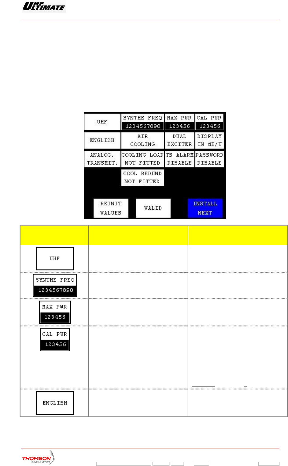
2.1.2. Installation windows
2.1.2.1. "INSTALLATION PARAMETERS Level 1" window
This window appears when the changeover switch SW1 on t
(MODAP version) or on the management system interconnectio witched
so that the dot is visible an
This window is used to change the transmitter configuration param
he exciter/CPU interconnection card
n card (SIRIUS version), is s
d that CPU board is reset.
eters stored in the CPU board.
CONTROL KEYS FUNCTIONS SELECTIONS
AVAILABLE/COMMENTS
Selects the transmitter frequency range.
Displays last selection.
VHF I, VHF III, UHF
Displays the RF synthesiser frequency value.
Displays last selection.
Pressing this key calls up the "NUMERICAL
VALUE" window in which this frequency can
be changed.
Selects the maximum transmitter power
(Maximum available RF power).
Displays last selection.
Pressing this key calls up the "NUMERICAL
VALUE" window in which this typical
transmitter power can be changed.
Selects the actual transmitter power
(Calibrated RF power)
Displays last selection.
Power level for which probes and power
output displays (bargraph) of the transmitter
are adjusted.
This level is a reference for the software.
This actual value is associated with the
power levels in % “100”, display in window,
and with the Auto Gain value “128” (Digital
transmitter) of ADAPT exciter.
At any time: CAL Power < MAX Power
Selects the language of the Local Control
Panel windows.
Displays last selection.
FRANCAIS, ENGLISH, ESPAGNOL
9932 V2
45321648.01 108 B E Checked 42 / 192
Numéro / Number Doc. Rev. Lan
g
u. 27/06/2006 Pa
g
e
Digital Liquid Cooled UHF
TV Equipment
Use of commands and description of indicators
Information contained is this document is confidential, is THOMSON property and cannot be disclosed in whatever form without prior written authorization of THOMSON.
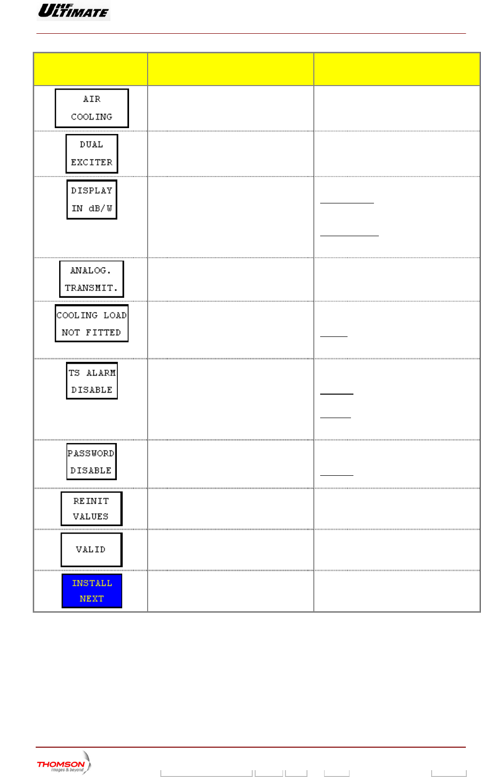
CONTROL KEYS FUNCTIONS SELECTIONS
AVAILABLE/COMMENTS
Selects the cooling type of the cabinet.
Displays last selection.
AIR COOLING, LIQUID COOLING
Selects the exciter configuration. SINGLE EXCITER, DUAL EXCITER,
Displays last selection. PASSIVE RESERVE, N+1
Selects the type of power unity
Displays last selection.
DISPLAY IN dB/W, DISPLAY IN %
If “%” is elected
.
, every RF power display is to
be expressed in %, excep mum power
which is expr
If “dB”
t maxi
essed in Watts.
is elected, every RF power display is
to be expressed in dB, except maximum
power which is expressed in Watts.
Selects the modulat
transmitter.
ion type of the
Displays last selection.
ANALOG. TRANSMIT;
DIGITAL TRANSMIT
Adapts the CPU software to suit the safety
interface hardware.
COOLING LO
COOLING L
AD NOT FITTED
OAD FITTED
FITTED : The safety of the load network
" key
indow.
cooling is active. The "COOLING LOAD
is visible in "INTERLOCK" w
Adapts the CPU software to suit the low
power alarm status.
TS ALARM DISABLE,
TS ALARM ENABLE
ISABLE
D : Without input Transport Stream
(TS), there is no low power alarm indication.
ENABLE: Indication low power alarm is
active when the input Transport Stream (TS)
is absence
Adapts the CPU software to suit one
password use for PCL unlocked.
PASSWORD DISABLE,
PASSWORD ENABLE
ENABLE : Using of password for PCL
unlocked
Sets the CPU board to the default
configuration.
Calls up the "WARNING 2" window.
This control keys may be used to repeat the
installation procedure.
Validates the configuration displayed on the
window.
Calls up the "TRANSMITTER INTERFACE
PARAMETERS" window.
9932 V2
45321648.01 108 B E Checked 43 / 192
Numéro / Number Doc. Rev. Lan
g
u. 27/06/2006 Pa
g
e
Digital Liquid Cooled UHF
TV Equipment
Use of commands and description of indicators
Information contained is this document is confidential, is THOMSON property and cannot be disclosed in whatever form without prior written authorization of THOMSON.
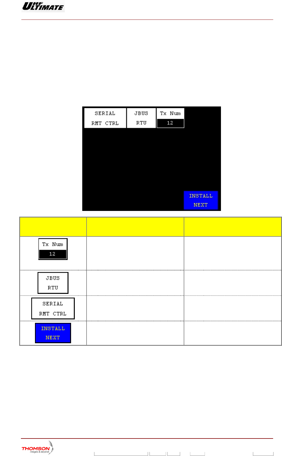
2.1.2.2. "TRANSMITTER INTERFACE PARAMETERS" window
This window appears when the changeover switch SW1 on the exciter/CPU interconnection card
(MODAP) or on the management system interconnection card (SIRIUS) is switched so that the dot is
visible and that CPU board is reset.
It is called up by pressing the "INSTALL NEXT" control keys in the "INSTALLATION PARAMETERS
Level 1" window.
This window is used to change the transmitter interface parameters stored in the CPU card.
CONTROL KEYS FUNCTIONS SELECTIONS
AVAILABLE/COMMENTS
Selects the transmitter ID number in N+1 or
Passive Reserve configurations.
Displays last selection.
he transmitter ID number is used for remote
control through an RS 232/485 connection.
Pressing this key calls up the "NUMERICAL
ALUE" window in which this two-digit
identification number can be changed.
T
V
Selects the type of JBUS protocol operation
for remote control
Displays last selection
JBUS ASCII
JBUS RTU
Selects the type of remote operation.
Displays last selection.
SERIAL RMT CTRL, PARALLEL RMT
CTRL, USER RMT CTRL
Calls up the "CABINET CONFIGURATION
PARAMETERS" window.
9932 V2
45321648.01 108 B E Checked 44 / 192
Numéro / Number Doc. Rev. Lan
g
u. 27/06/2006 Pa
g
e
Digital Liquid Cooled UHF
TV Equipment
Use of commands and description of indicators
Information contained is this document is confidential, is THOMSON property and cannot be disclosed in whatever form without prior written authorization of THOMSON.
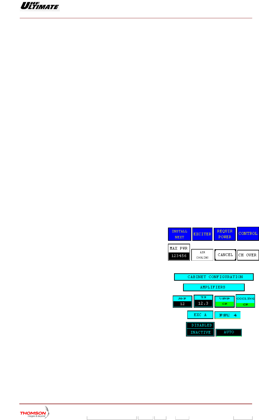
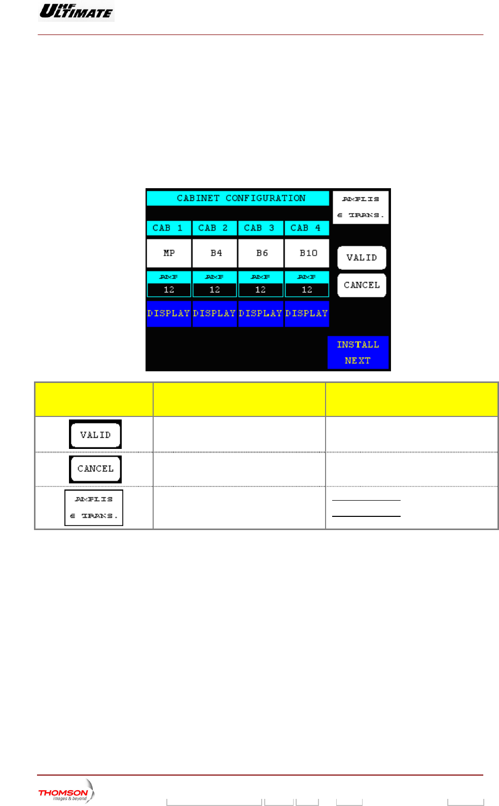
2.1.2.3. "CABINET CONFIGURATION PARAMETERS" window
This window appears wh SW1 on th
(MODAP) or on the manag rconnection card (S hed so that the dot is
visible and that CPU boar set.
It is called up by pressing the "INSTALL NEXT" control keys in the "TRANSMITTER INTERFACE
PARAMETERS" window.
This window is used to change the cabinet configuration paramete s sto
en the changeover switch e exciter/CPU interconnection card
IRIUS), is switcement system inte
d is re
r red in the CPU board.
CONTROL KEYS FUNCTIONS SELECTIONS
AVAILABLE/COMMENTS
the amplifier location in each of the cabinet
selected.
Validates the cabinet selection and detects
previous values
Cancels the entry and calls back the
Selects the number of currents measured by
amplifier unit (*).
Displays last selection
AMPLIS 6 TRANS. : 6 currents measured
AMPLIS 8 TRANS. : 8 currents measured
9932 V2
45321648.01 108 B E Checked 45 / 192
Numéro / Number Doc. Rev. Lan
g
u. 27/06/2006 Pa
g
e
Digital Liquid Cooled UHF
TV Equipment
Use of commands and description of indicators
Information contained is this document is confidential, is THOMSON property and cannot be disclosed in whatever form without prior written authorization of THOMSON.
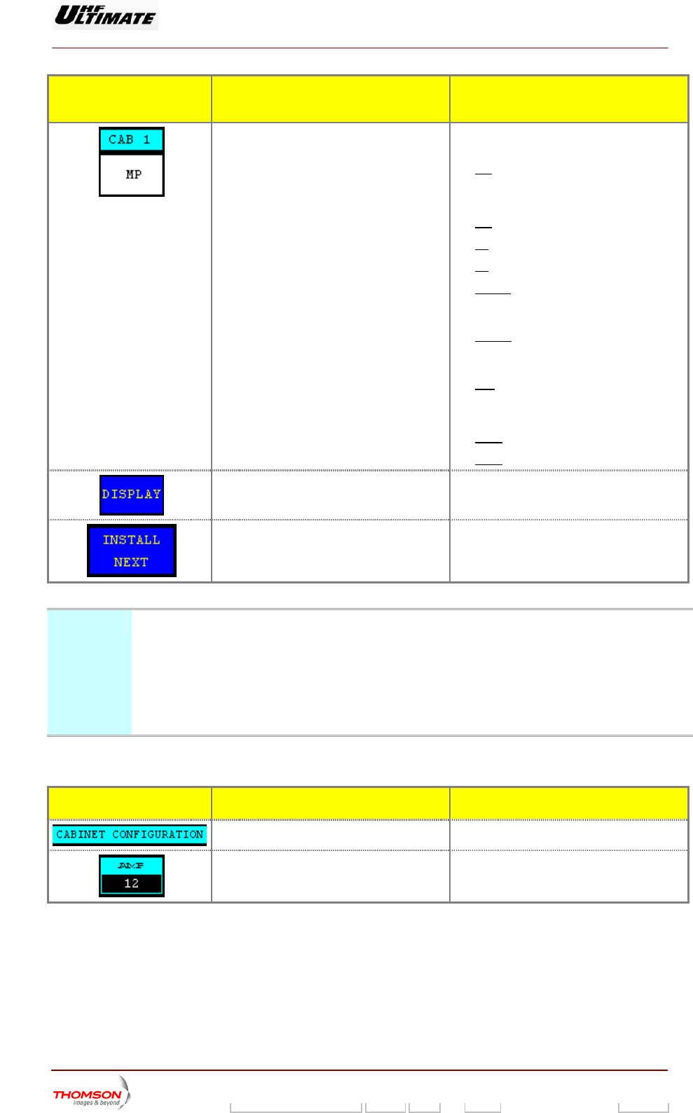
CONTROL KEYS FUNCTIONS SELECTIONS
AVAILABLE/COMMENTS
Selects the type of the cabinet. NO, MP, B4, B6, B10, B16AG, B16NG, B20,
AFF4, AFF8
♦
Displays last selection
NO: No use
OPTIMUM / ULTIMATE FAMILY
♦ MP: MPNG Cabinet,
♦ B4: Cabinet consist of 4 RF amplifiers,
♦ B6: Cabinet consist of 6 RF amplifiers,
♦ B16AG: Cabinet consist of 16 RF
amplifiers (Old generation cabinet: the
mai SUs)
♦ B16NG
n MUX card “MASTER” feed 4 P
: Cabinet consist of 16 RF
amplifiers (New generation cabinet: The
main MUX card “MASTER” feed 5 PSUs)
♦ B20: Cabinet consist of 20 RF amplifiers
AFFINITY FAMILY
♦ AFF4: Cabinet consist of 4 RF amplifiers
♦ AFF8: Cabinet consist of 8 RF amplifiers
Calls up the " AMPLIFIER LOCATION "
window
ys may be used to selected This control ke
the amplifier location
Calls up the "ADAPT INSTALLATION
PARAMETERS" window.
(*) Note ♦ In case of unit (61388768 or 61388769) ,the window
‘’RF amplifier’’ include 6 current measurements.
In case of he window ‘’RF amplifier’’ include 8
current measurem
window ‘’RF amplifier’’ include 6 current
measurements.
using the 2400W VHF amplifier
♦ using the 1600W VHF amplifier unit
ents.
,t
♦ In case of using the UHF amplifier unit , the
MESS GE AFUNCTIONS DISPLAY/COMMENTS
Gives the window name.
Displays the detecte
number including into this cabinet.
d amplifier location
9932 V2
45321648.01 108 B E Checked 46 / 192
Numéro / Number Doc. Rev. Lan
g
u. 27/06/2006 Pa
g
e
Digital Liquid Cooled UHF
TV Equipment
Use of commands and description of indicators
Information contained is this document is confidential, is THOMSON property and cannot be disclosed in whatever form without prior written authorization of THOMSON.
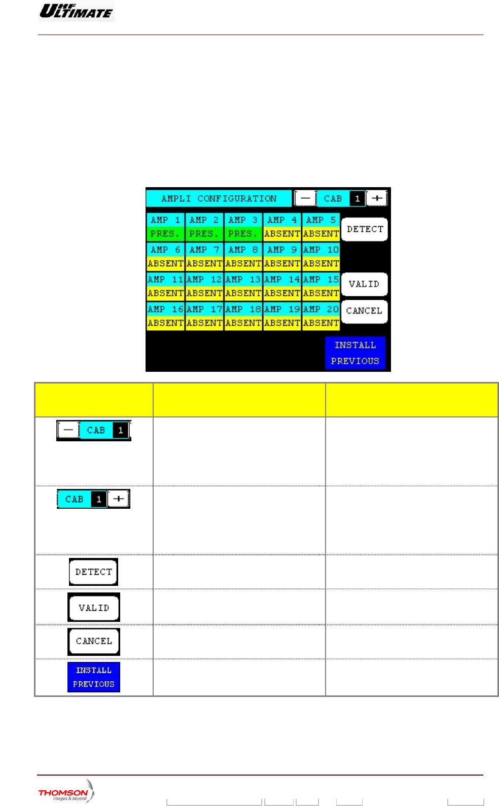
2.1.2.3.1. "LOCATION AMPLIFIER" window
and
U
is called
PARAMETER
This window e amplifier
cation store
This window appears when the changeover switch SW1 or S9 is switched so that the dot is visible
that CP board is reset.
It up by pressing the "DISPLAY " control keys in the " CABINET CONFIGURATION
S" window.
displays the location of RF amplifier in selected cabinet. It is used to change th
lo d in the CPU board.
CONTROL KEYS FUNCTIONS SELECTIONS
AVAILABLE/COMMENTS
Decrements the cabinet number (*). The ng from the
decrementation is displayed in the message
is
number resulti
window between the "+ CAB" and "- CAB"
control keys.
Command is disabled while the PCL
locked (disabled).
Increments the cabinet number (*).
ed in the message
window between the "+ CAB" and "- CAB"
control keys.
Command is disabled while the PCL is
locked (disabled).
The number resulting from the
incrementation is display
Detects the amplifier location in cabinet
selected.
Validates the entry
Cancels the entry and calls back the
previous windows
Calls up the "CABINET CONFIGURATION
PARAMETERS" window.
(*) : Operating only when there is more than one cabinet.
9932 V2
45321648.01 108 B E Checked 47 / 192
Numéro / Number Doc. Rev. Lan
g
u. 27/06/2006 Pa
g
e
Digital Liquid Cooled UHF
TV Equipment
Use of commands and description of indicators
Information contained is this document is confidential, is THOMSON property and cannot be disclosed in whatever form without prior written authorization of THOMSON.
MESSAGE FUNCTIONS DISPLAY/COMMENTS
Gives the window name.
Toggles between pres
vision and sound amplifier locatio
ent and absent or
n
Displays the amplifier location status into this
cabinet
Displays last selection
transmitter
ENT for analogue
PRES. / ABSENT for digital
VISION / SOUND. / ABS
transmitter
Shows the number of the particular
to which the data displayed in this
cabinet
window
refer.
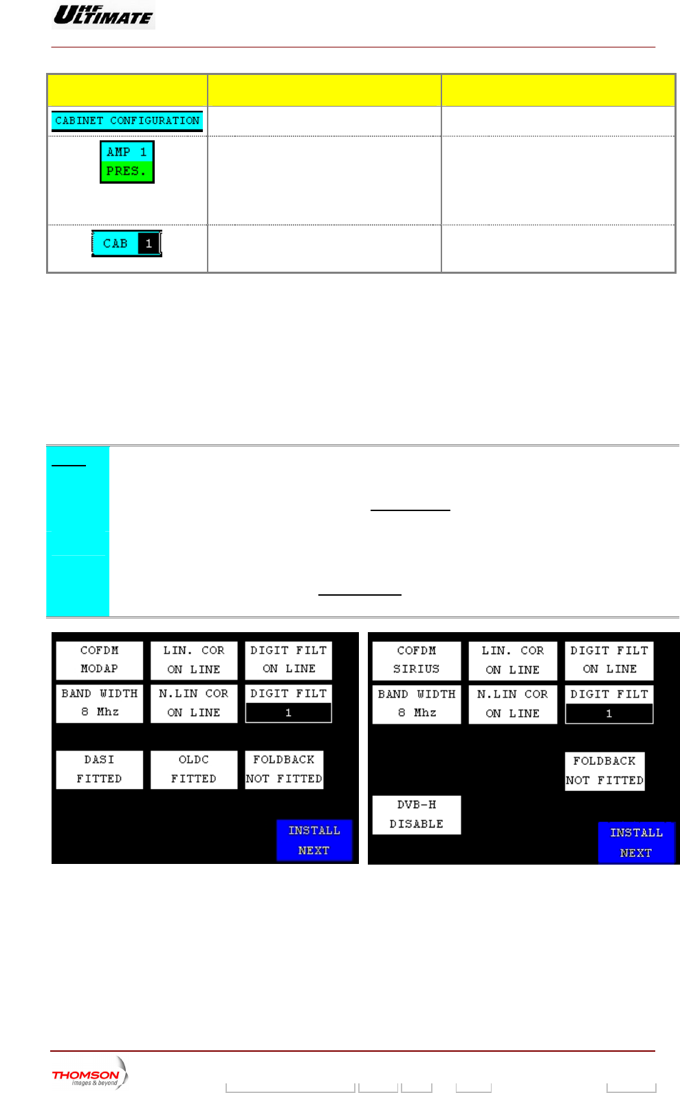
2.1.2.4. "INSTALLATION ADAPT PARAMETERS" window
This window appears when the changeover switch SW1 on the PU interconnection card
(MODAP) or on the management system interconnection card (S
visible and that CPU board is reset.
It is called up by pressing iBINET"
window.
This window is used to cha n adaptation parameters stored in the CPU card.
exciter/C
IRIUS) is switched so that the dot is
the "INSTALL NEXT" control keys n the "CONFIGURATION CA
nge the configuratio
Note :
♦DAP Vers
To set up a figuration of the modulator, the three corrections (ALE,
LUT and OLDC) shoul
MO ion only
new parameter con
d be set to the FIXED mode. The control keys can
AINT Level 4" windows.
be defined in
the "MISCELLANEOUS" windows and "CONTROL M
♦ SIRIUS Versi
To set up a new parameter configuration of the mod
LUT) should be set to the FIXED mode
on only
ulator, the two corrections (ALE, and
. The
"MISCELLANEOUS" windows and "CONTROL MA
control keys can be defined in the
INT Level 4" windows.
MODAP Version SIRIUS Version
9932 V2
45321648.01 108 B E Checked 48 / 192
Numéro / Number Doc. Rev. Lan
g
u. 27/06/2006 Pa
g
e
Digital Liquid Cooled UHF
TV Equipment
Use of commands and description of indicators
Information contained is this document is confidential, is THOMSON property and cannot be disclosed in whatever form without prior written authorization of THOMSON.
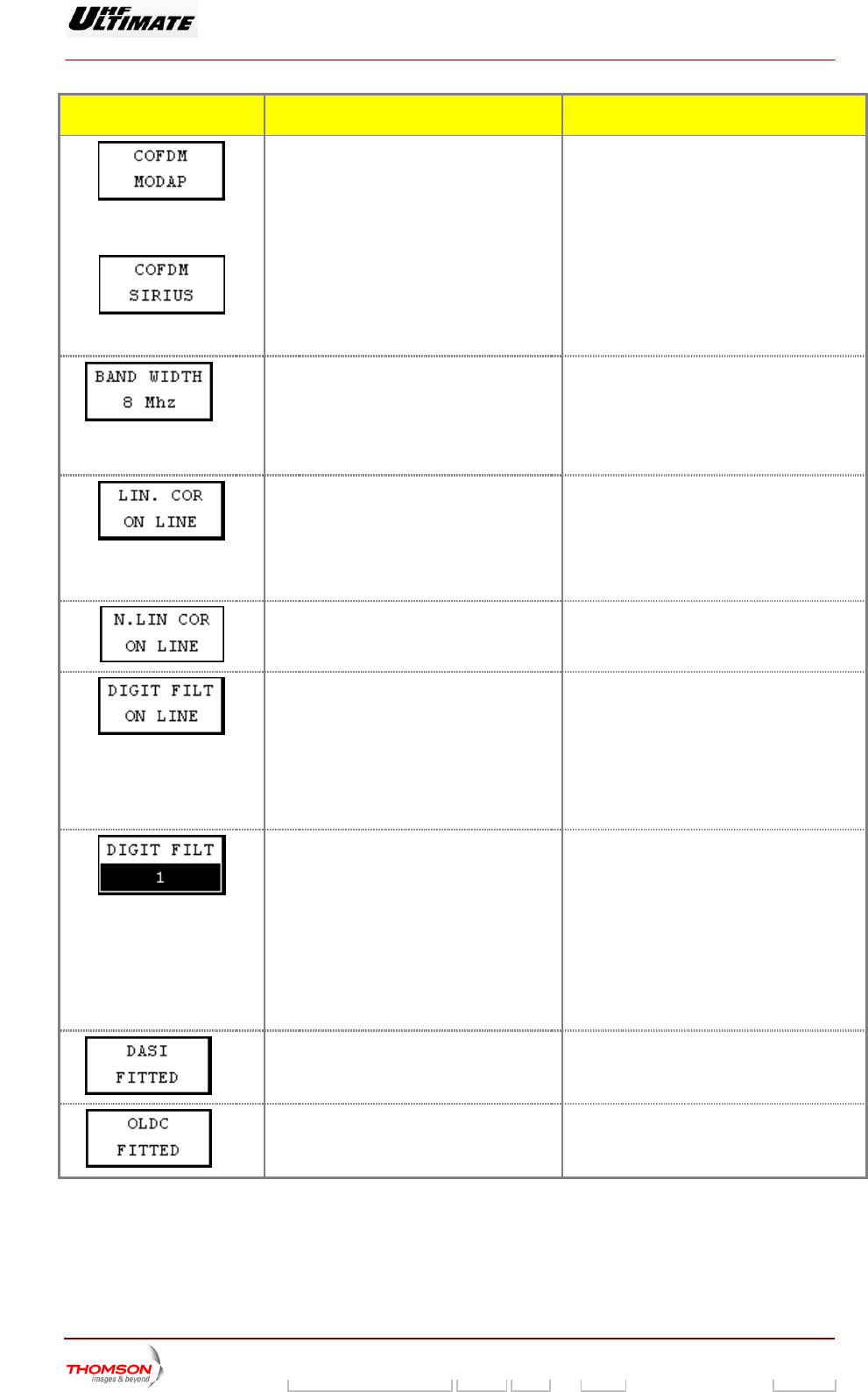
CONTROL KEYS FUNCTIONS SELECTIONS AVAILABLE/COMMENTS
OR
Displays last selection.
ARD / COFDM EXT /
Selects the type of modulator processing the 8VSB BO
input signal. IFIQ BOARD / COFDM MODAP /
COFDM SIRIUS / FLO SIRIUS
(2)
signal
Displays last selection.
BAND WIDTH 7MHz /
BAND WIDTH 8MHz /
Selects the band width of the canal for DVBT BAND WIDTH 6MHz /
This control key is available in COFDM
MODAP or COFDM SIRIUS (Internal DVB-T
Modulator)
Adap
hard
ts the CPU it the DAP
ware (Adaptive Linear Equalizer).
Displa
LIN. COR NOT FITTED/ LIN. COR ON LINE /
LIN. COR ON LINE / LIN. COR BYPASSED
software to su ♦ MODAP version
ys last selection. LIN. COR BYPASSED
♦ SIRIUS version
Activa
corre ok Up Table).
Displays last selection.
tes or bypasses the DAP non linearity
ctor (Lo
N. LIN. COR ON LINE /
N. LIN. COR BYPASSED
Adap
hardw
Displays last selection. ON LINE /
ON LINE /
ts the CPU software to suit the DAP
are (digital filter).
♦ MODAP version
DIGIT FILT NOT FITTED /
DIGIT FILT
DIGIT FILT BYPASSED
♦ SIRIUS version
DIGIT FILT
DIGIT FILT BYPASSED
Selects the table for the digital filter.
Displa
normally used on MODAP Exciter is
normally used on SIRIUS Exciter is
Pressing this key calls up the "NUMERICAL
ys last selection.
Values: 1 to 5
This value is defined in factory:
♦ Value
equal at 5
♦ Value
equal at 1.
VALUE" window in which this value can be
changed.
(1)
dap
ardw
Displa
A
h
ts the CPU software to suit the MODAP
are (Double ASI input).
DASI NOT FITTED / DASI FITTED
ys last selection.
(1)
Adap
hardw
Displays last selection.
NOT FITTED
ts the CPU software to suit the MODAP
are (OLDC).
OLDC FITTED / OLDC
9932 V2
45321648.01 108 B E Checked 49 / 192
Numéro / Number Doc. Rev. Lan
g
u. 27/06/2006 Pa
g
e
Digital Liquid Cooled UHF
TV Equipment
Use of commands and description of indicators
Information contained is this document is confidential, is THOMSON property and cannot be disclosed in whatever form without prior written authorization of THOMSON.
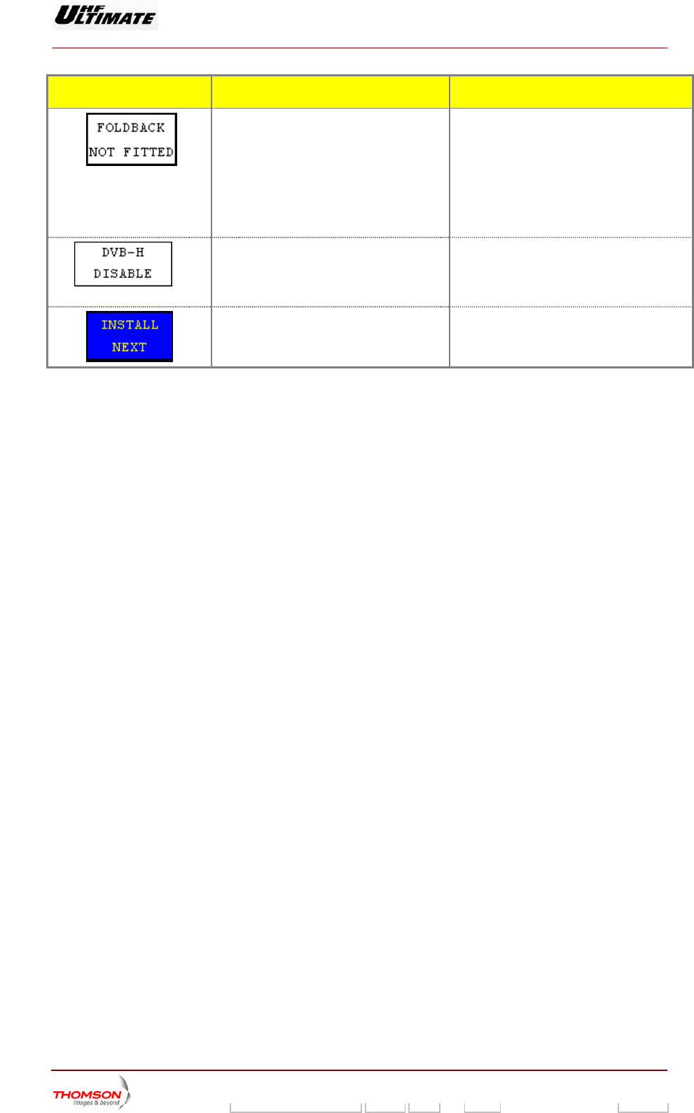
CONTROL KEYS FUNCTIONS SELECTIONS AVAILABLE/COMMENTS
Sets
accor the Americanisation unit
hardw
K FITTED
l on antenna VSWR fault will be
In the second case that the power control on
antenna VSWR fault will be is produce by
the CPU board to the configuration
ding to
FOLDBACK NOT FITTED,
FOLDBAC
are type 37418880 This option unit must be present so that the
power contro
progressively produce through an algorithm.
stairway (-3dB, -6dB and halt ‘no power”)
(2)
Adap n
COFD
spla
meters are not
arameters are
ts the CPU software. Visible o DISABLE: The DVB-H para
M SIRIUS modulator only
Di ys last selection.
accessible via the DVB-T CONTROL screen.
ENABLE: The DVB-H p
available via the DVB-T CONTROL screen.
Calls ET INSTALLATION
PARAMETERS" w
up the "ETHERN
indow.
(1) : Available on MODAP version only
(2) : Unavailable on MediaFLO modulator
9932 V2
45321648.01 108 B E Checked 50 / 192
Numéro / Number Doc. Rev. Lan
g
u. 27/06/2006 Pa
g
e
Digital Liquid Cooled UHF
TV Equipment
Use of commands and description of indicators
Information contained is this document is confidential, is THOMSON property and cannot be disclosed in whatever form without prior written authorization of THOMSON.
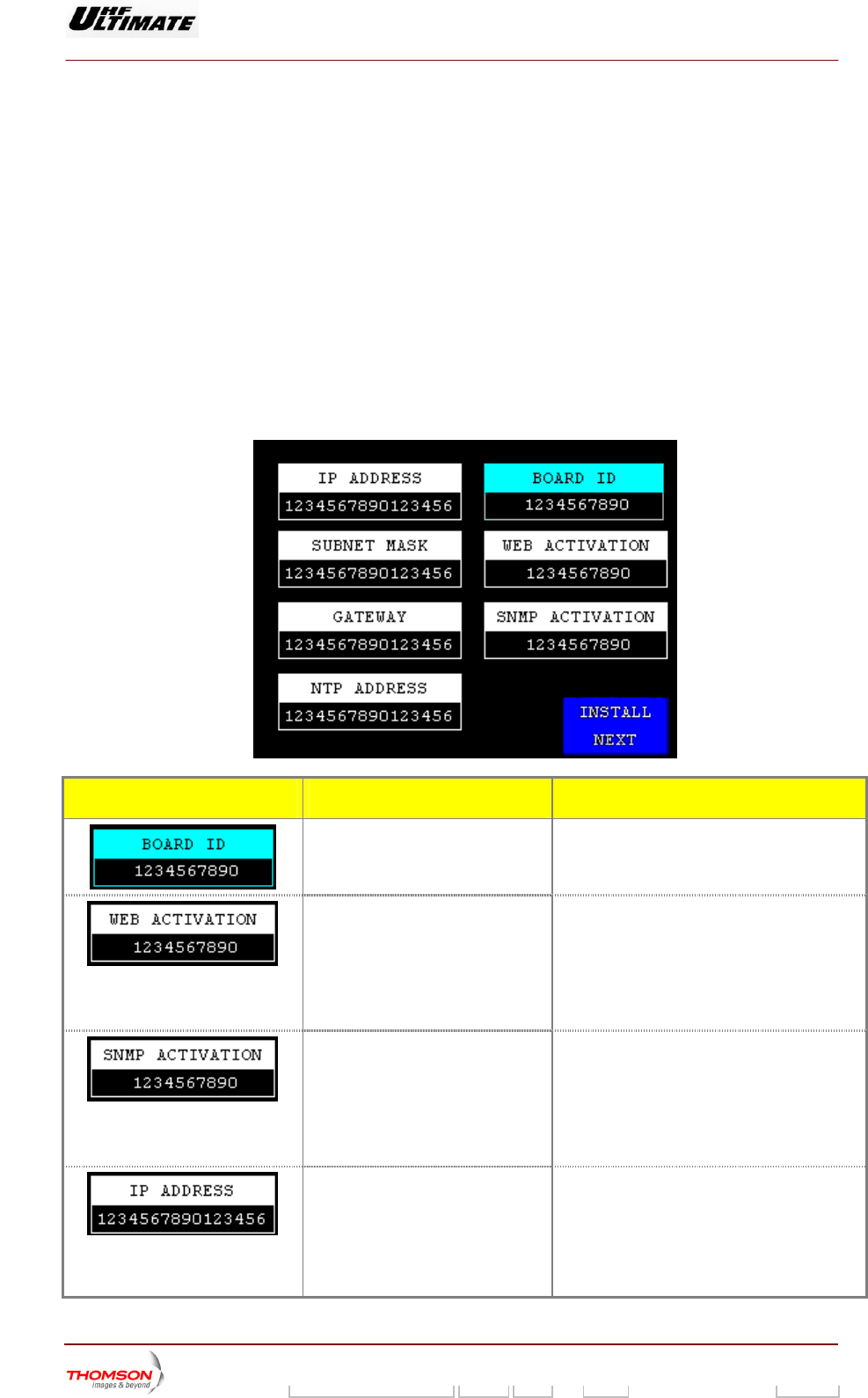
2.1.2.5. "ETHERNET INSTALLATION PARAMETERS" window
This window appears when the changeover switch SW1 or S9 is switched so that the dot is visible and
It is called up by pressing the "INSTALL NEXT" control keys in "INSTALLATION EXCITER
PARAMETERS" window.
This window is used to change the Ethernet configuration parameters used by the communication
network. It is only available with TH860 CPU Board.
that CPU board is reset.
♦ For Digital Transmitter
It is called up by pressing the "INSTALL NEXT" control keys in "INSTALLATION ADAPTATION
PARAMETERS" window.
♦ For Analogue Transmitter
MESSAGE & CONTROL KEYS FUNCTIONS SELECTIONS AVAILABLE/COMMENTS
Displays the identification number of
the CPU board
This reference is single and associated to one
CPU board
Used to insert the WEB activation
code.
Displays the WEB activation code,
without option in operation the
control keys displays: “0”
THALES produces activation code of the
“Agent WEB” option. This code is single and
associated to the identification number of the
CPU board
Pressing this key calls up the "NUMERICAL
VALUE" window in which this code value can
be inserted.
Used to insert the SNMP activation
code.
Displays the SNMP activation code,
without option in operation the
control keys displays: “0”
THALES produces activation code of the
“Agent SNMP” option. This code is single and
associated to the identification number of the
CPU board
Pressing this key calls up the "NUMERICAL
VALUE" window in which this code value can
be inserted.
Used to Insert the IP address of the
transmitter in an Ethernet network.
Displays the IP address in operation.
When the Ethernet network is not
operated the control keys must
display: “0.0.0.0”
Your network administrator gives the IP
address.
NOTA : IP wrong address disturbs the
network.
Calls up the "NUMERICAL VALUE" window
9932 V2
45321648.01 108 B E Checked 51 / 192
Numéro / Number Doc. Rev. Lan
g
u. 27/06/2006 Pa
g
e
Digital Liquid Cooled UHF
TV Equipment
Use of commands and description of indicators
Information contained is this document is confidential, is THOMSON property and cannot be disclosed in whatever form without prior written authorization of THOMSON.
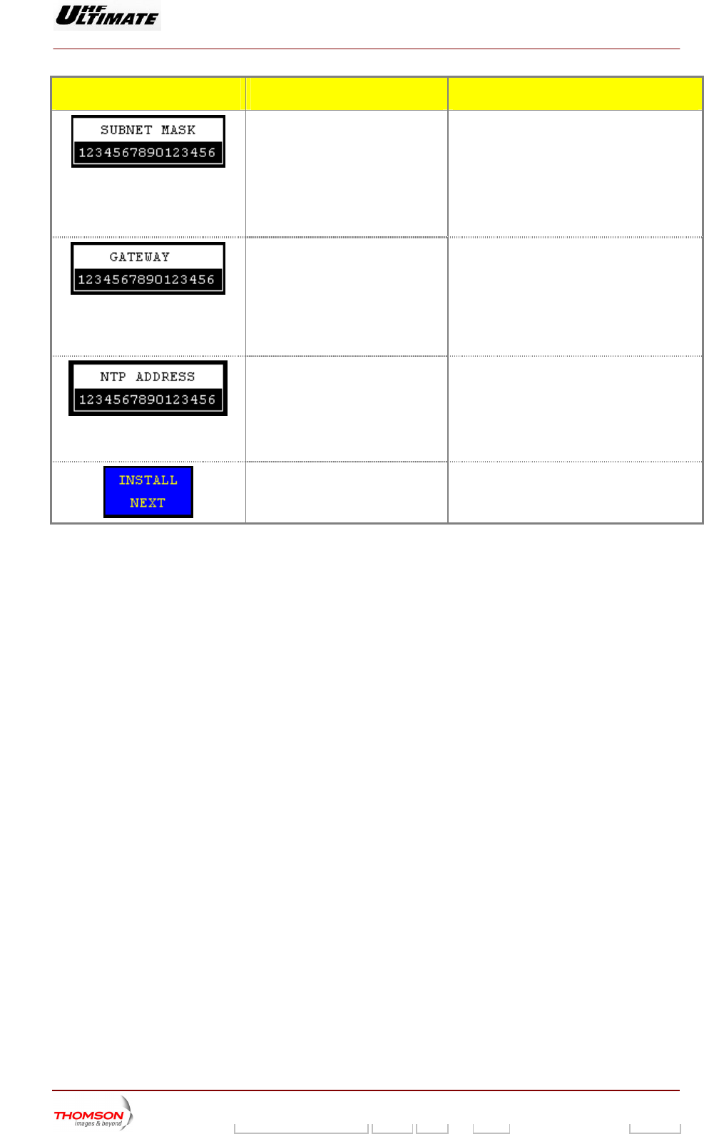
MESSAGE & CONTROL KEYS FUNCTIONS SELECTIONS AVAILABLE/COMMENTS
Used to Insert the sub-net mask
Displays the Sub-net mask number
operated the control keys must
display: “0.0.0.0”
Your network administrator gives the subset
This number, associated with IP address,
disturbs the network.
Calls up the "NUMERICAL VALUE" window
number mask number.
in operation.
When the Ethernet network is not
identifies the network inside your transmitter is.
NOTA : Subset mask wrong number
Used to Insert the IP address of
gateway
Displays the
tion.
When the Ethernet network is not
operated the control keys must
display: “0.0.0.0”
Your network administrator gives the gateway
IP address.
NOT
th
C
the IP address of
gateway in opera
A : Gateway IP wrong address disturbs
e network.
alls up the "NUMERICAL VALUE" window
Used to Insert t
work Time Proto
he IP address of Net
col (NTP) SERVER.
Displays the IP address in operation.
When the Ethernet network is not
operated the control keys must
display: “0.0.0.0”
Y r network administrator gives the IP
address of the NTP server.
NOTA : IP wrong address of the NTP server
disturbs the network.
Calls up the "NUMERICAL VALUE" window
ou
Calls up the "INSTALLATION
PARAMETERS Level 1" window.
9932 V2
45321648.01 108 B E Checked 52 / 192
Numéro / Number Doc. Rev. Lan
g
u. 27/06/2006 Pa
g
e
Digital Liquid Cooled UHF
TV Equipment
Use of commands and description of indicators
Information contained is this document is confidential, is THOMSON property and cannot be disclosed in whatever form without prior written authorization of THOMSON.
2.1.3. Warning windows
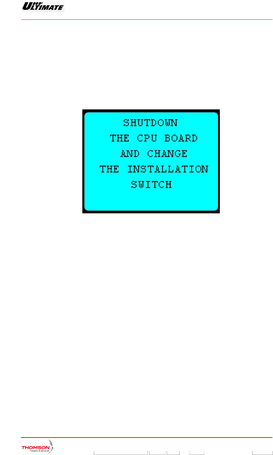
2.1.3.1. Warning window "WARNING 1"
This window appears when configuration parameters are validated.
It prompts the operator to switch the CPU board off and then on again, by using the changeover switch
SW1 or S9; this operation switches the power supply feeding the CPU board off and on in order to
reset the transmitter with its new configuration.
9932 V2
45321648.01 108 B E Checked 53 / 192
Numéro / Number Doc. Rev. Lan
g
u. 27/06/2006 Pa
g
e
Digital Liquid Cooled UHF
TV Equipment
Use of commands and description of indicators
Information contained is this document is confidential, is THOMSON property and cannot be disclosed in whatever form without prior written authorization of THOMSON.
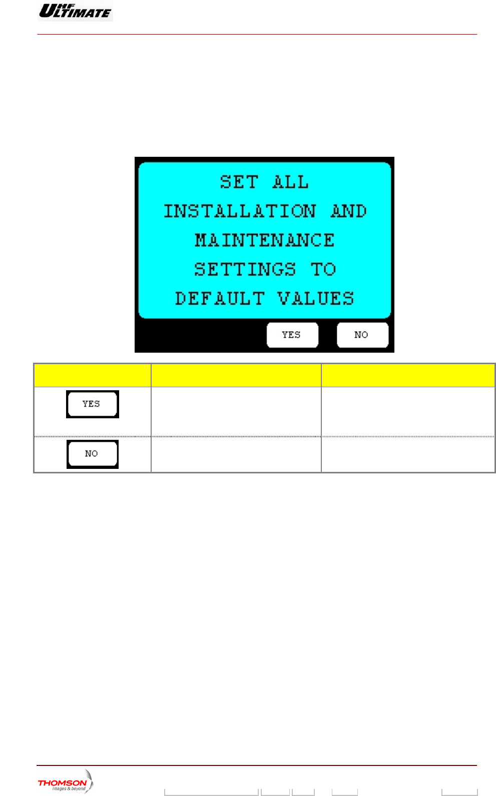
2.1.3.2. Warning window "WARNING 2"
It appears when the changeover switch SW1 or S9 is switched so that the dot is visible and that CPU
board is reset.
This window appears after pressing "REINIT VALUES" in the "INSTALLATION PARAMETERS
ow.
Level 1" wind
CONTROL KEYS FUNCTIONS SELECTIONS AVAILABLE/COMMENTS
Validates the window. After pressing this control keys, the CPU
board is set to the default configuration.
The "REINIT VALUES" control keys may be
used for a new installation procedure.
Cancels the window.
9932 V2
45321648.01 108 B E Checked 54 / 192
Numéro / Number Doc. Rev. Lan
g
u. 27/06/2006 Pa
g
e
Digital Liquid Cooled UHF
TV Equipment
Use of commands and description of indicators
Information contained is this document is confidential, is THOMSON property and cannot be disclosed in whatever form without prior written authorization of THOMSON.
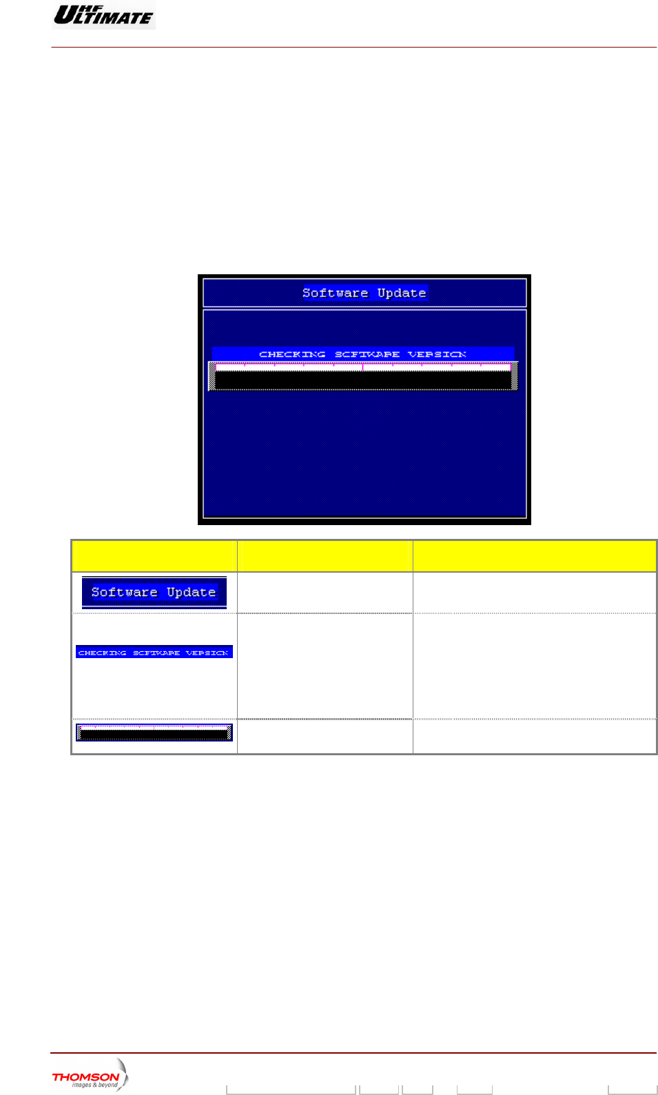
2.1.3.3 Warning window "Software UPDATE. "
the new CPU software.
ot”.
Press the « RESET » button of ning the appropriate breakers.
This window displays the download progress of the new CPU software. It is only available with TH860
CPU BOARD.
This window is called up by three following conditions:
♦ Inserting PCMCIA card in flash card drive. This card contains
♦ Transmitter must be in installation mode changeover “SW1” or S9 is on position “visible d
CPU board or Power off CPU board, ope
MESSAGE FUNCTIONS SELECTIONS AVAILABLE/COMMENTS
Give the window name
Display the down load operating
mode.
PLEASE WAIT.
CHECKING SOFTWARE VERSION
ERASING FLASH MEMORY
PROGRAMMING FLASH MEMORY
DONE, PLEASE WAIT.
Displays the down load
progress.
9932 V2
45321648.01 108 B E Checked 55 / 192
Numéro / Number Doc. Rev. Lan
g
u. 27/06/2006 Pa
g
e
Digital Liquid Cooled UHF
TV Equipment
Use of commands and description of indicators
Information contained is this document is confidential, is THOMSON property and cannot be disclosed in whatever form without prior written authorization of THOMSON.
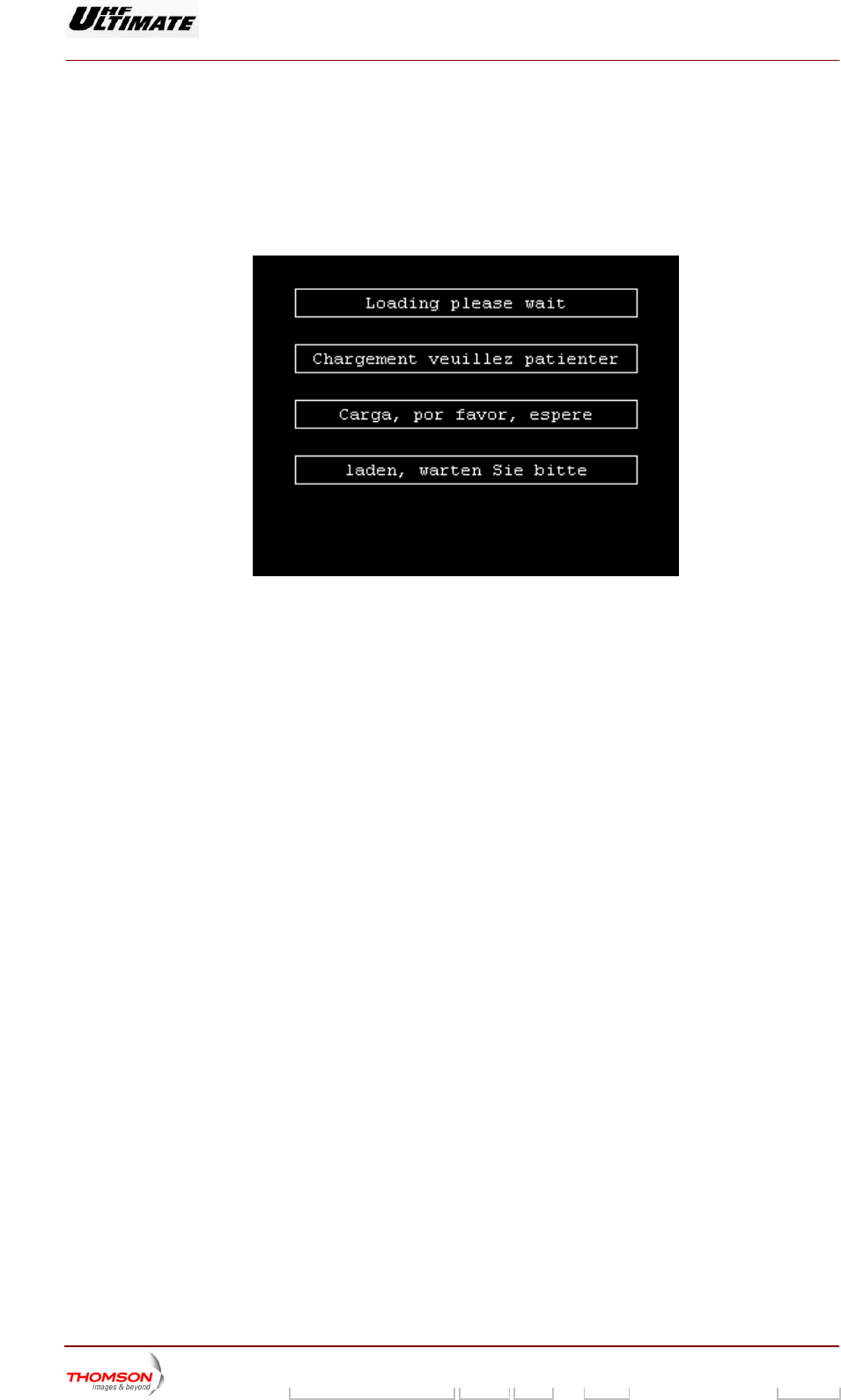
2.1.3.4. Warning window "WARNING 3"
This window appears whe art up, the communic een the CPU and tactile
screen is not still ready.
It prompts the operator to wait a moment.
n the CPU board st ation betw
9932 V2
45321648.01 108 B E Checked 56 / 192
Numéro / Number Doc. Rev. Lan
g
u. 27/06/2006 Pa
g
e
Digital Liquid Cooled UHF
TV Equipment
Use of commands and description of indicators
Information contained is this document is confidential, is THOMSON property and cannot be disclosed in whatever form without prior written authorization of THOMSON.
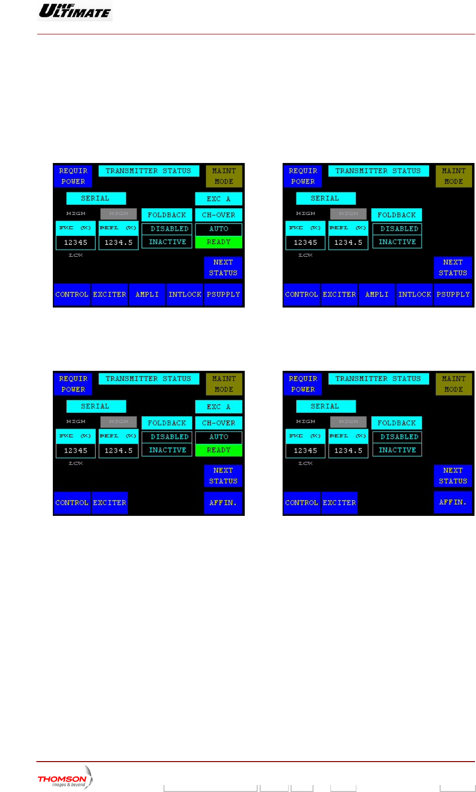
2.1.4. "TRANSMITTER STATUS" window
This window appears when the transmitter is switched on and
behind the CPU o switched so that the dot is not visible.
It can also be called up by pre
AMILY OR ULTIMATE FA
the changeover switch SW1 or S9,
b ard, is
ssing the "STATUS" control keys on
OPTIMUM F
the other windows.
MILY
7 : Single Drive TransmFigure 6 : Dual Drive Transmitter Figure itter
AFFINTY FAMILY
Figure 8 : Dual Drive Transmitter
Figure 9 : Single Driv
e Transmitter
9932 V2
45321648.01 108 B E Checked 57 / 192
Numéro / Number Doc. Rev. Lan
g
u. 27/06/2006 Pa
g
e
Digital Liquid Cooled UHF
TV Equipment
Use of commands and description of indicators
Information contained is this document is confidential, is THOMSON property and cannot be disclosed in whatever form without prior written authorization of THOMSON.
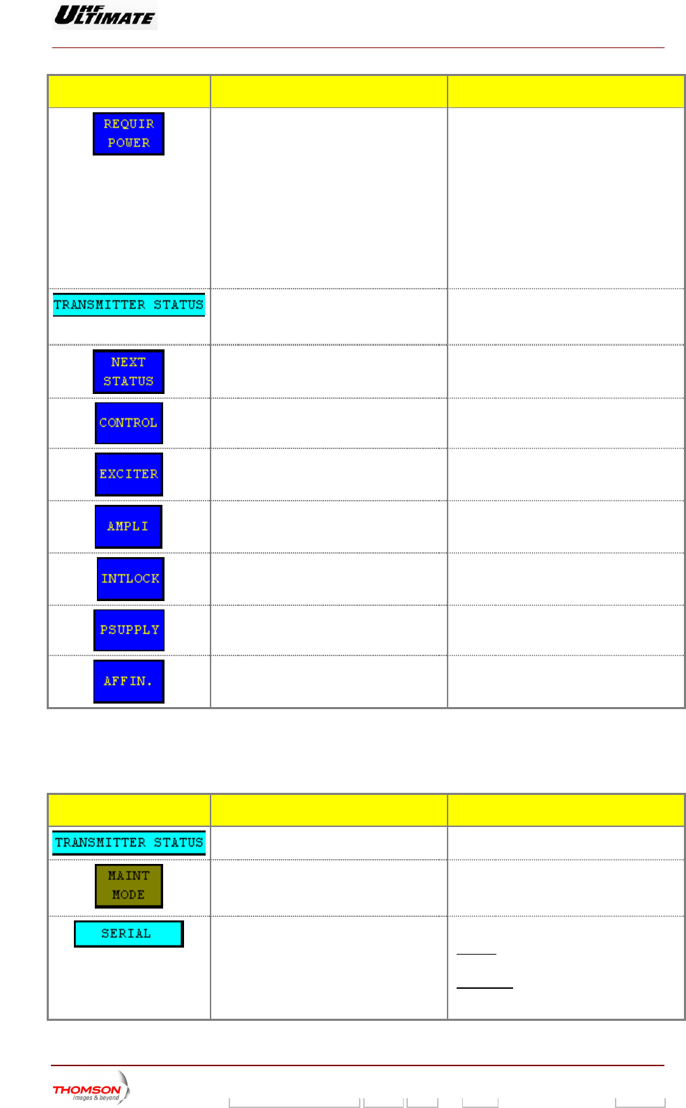
CONTROL KEYS FUNCTIONS DISPLAY/COMMENTS
(Reduction power). (3) transmitter
Calls up the "REQUIRED POWER" window ♦ ATSC transmitter OR ANALOG
This control keys is available in Maintenance
♦ DVB-T transmitters
trol keys is available in Maintenance
mode and MFN mode operation only.
Control key invisible in Normal mode or SFN
mode operation.
mode only.
Control key invisible in Normal mode only.
This con
Calls up the "GO HOME AND VIEW
INSTALLATION PARAMETERS" window.
Also displays the window title.
Calls up the "STATUS" window.
Calls up the "CONTROL Level 1" window.
Calls up the "EXCITER Level 1" window.
Calls up the "AMPLIFIERS" window. (a)
Calls up the "INTLOCK" window. (a)
Calls up the "POWER SUPPLY" window. (a)
Calls up the "AFFINITY" window. (b)
(a): Not Visible for AFFINITY family
(b): Not Visible for OPTIMUM or ULTIMATE families
(3): Unavailable for MedaFLO modulator
MESSAGE FUNCTIONS DISPLAY/COMMENTS
Gives the window name.
Displays the c mode of the
transmitter (m or normal
MAINT M
linking message to indicate that the
aintenance mode is operating
urrent operating
aintenance mode
mode).
ODE / NORMAL MODE
B
m
Displays the current remote control mode o
the transmitter.
f SERIAL / PARALLEL
SERIAL : Remote control through a
RS432/485 serial link.
PARALLEL (Remote controls and
indicators): Remote control through hard
wired connections.
9932 V2
45321648.01 108 B E Checked 58 / 192
Numéro / Number Doc. Rev. Lan
g
u. 27/06/2006 Pa
g
e
Digital Liquid Cooled UHF
TV Equipment
Use of commands and description of indicators
Information contained is this document is confidential, is THOMSON property and cannot be disclosed in whatever form without prior written authorization of THOMSON.
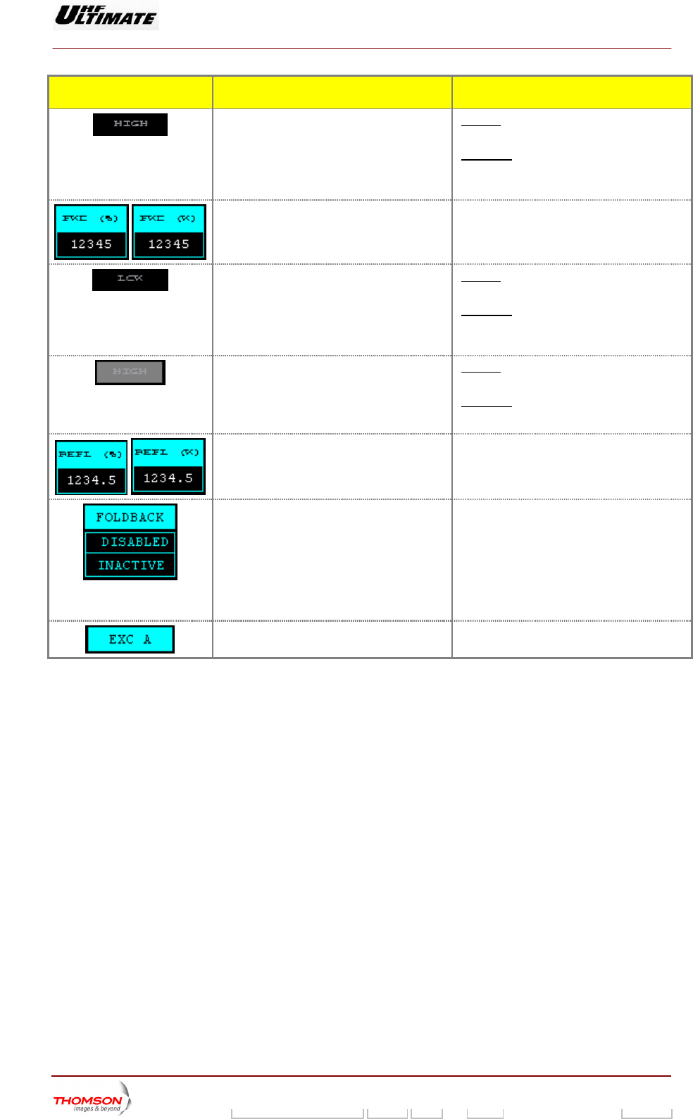
MESSAGE FUNCTIONS DISPLAY/COMMENTS
Indicates a higher value than the high alarm
threshold value.
Flashes if the transmitted power exceeds the
maximum power threshold value.
Otherwise not visible.
The alarm threshold is set using the «RF
THRESHOLD» window.
Displays the transmitted RF power value This value is expressed in watts or as a
percentage of the calibrated power value
according with your installation choice
Indicates a lower value than the low alarm
threshold value.
Flashes if the transmitted power is lower
than the minimum power threshold value.
herwiseOt not visible.
he alarm threshold is set using the «RF
THRESHOLD» window.
T
Indicates a higher value than the threshold
value.
Flashes if the reflected power (reverse
power) exceeds 3% of calibrated power
wise
Other not visible.
eshold value (3%) is unchanging The thr
Displays the reflected power value Th
is value is expressed in watts or as a
percentage of calibrated power value
according with your installation choice
To indicate the reflected (reserve)
control mode.
power OLDBACK ENABLED: When the reflected
ower value is higher than the threshold
value (3%) the power control is progressively
produce through an algorithm.
OLDBACK DISABLED: When the reflected
power value is higher than the threshold
value (3%) the power control is produce by
stairway (-3dB, -6dB and halt ‘no power”)
F
p
F
EXC A / EXC B Indicates the exciter selected.(*)
9932 V2
45321648.01 108 B E Checked 59 / 192
Numéro / Number Doc. Rev. Lan
g
u. 27/06/2006 Pa
g
e
Digital Liquid Cooled UHF
TV Equipment
Use of commands and description of indicators
Information contained is this document is confidential, is THOMSON property and cannot be disclosed in whatever form without prior written authorization of THOMSON.
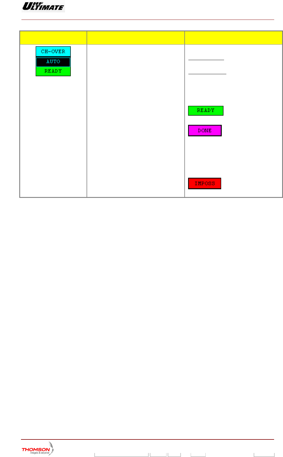
MESSAGE FUNCTIONS DISPLAY/COMMENTS
To indicate the exciter changeover mode
atic mode (Lower indicator).(*)
Upper indicator
(Upper indicator).
To indicate the exciter changeover status in
autom
CH-OVER MAN (Manual) : only when
operator gives a command.
CH-OVER AUTO : automatic changeover
ulty.
Lower indicator
CH ER NOT DONE /
CH OVER IMPOSSIBLE
when the selected exciter is fa
OVER DONE / CH OV
: the changeover system is
ready for an automatic switch over.
: the changeover system is
no longer available and it is necessary to
change the exciter selected or to carry out a
transmitter "RESET" (in this latter case, care
must be taken because fault data for all
faults which have disappeared will be erased
together with their consequences; similarly
for all selections carried out on the PCL).
: an attempt to carry out an
automatic changeover has failed.
(*) : Only in Dual Drive Version
9932 V2
45321648.01 108 B E Checked 60 / 192
Numéro / Number Doc. Rev. Lan
g
u. 27/06/2006 Pa
g
e
Digital Liquid Cooled UHF
TV Equipment
Use of commands and description of indicators
Information contained is this document is confidential, is THOMSON property and cannot be disclosed in whatever form without prior written authorization of THOMSON.
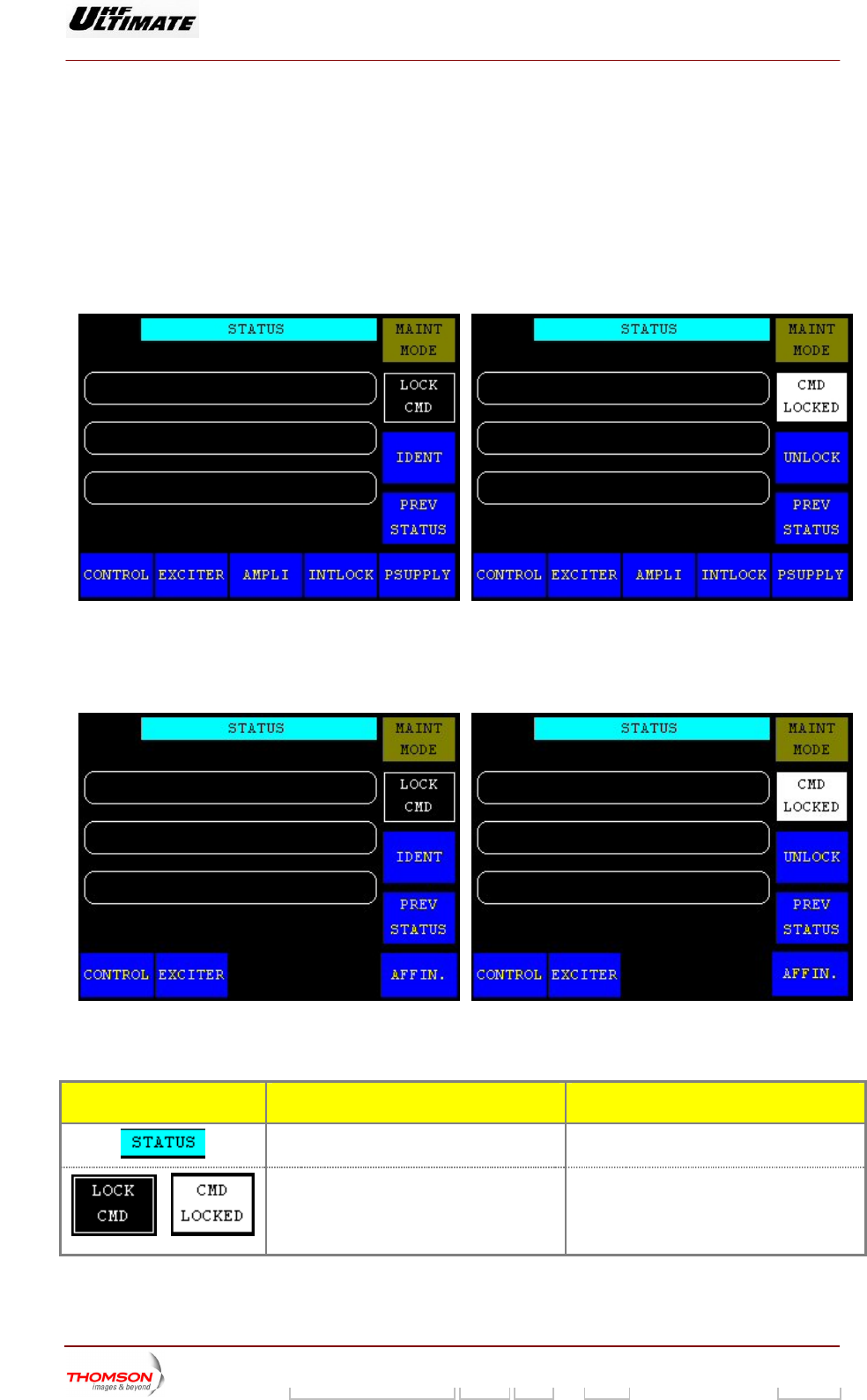
2.1.5. "STATUS" indow
This window s called up s in the "TRANSMITTER
STATUS" window.
It provides access to comm "STATUS" window.
w
i by pressing the "NEXT STATUS" control key
ands and information which are only available in the
OPTIMUM FAMILY OR ULTIMATE FAMILY
Figure 10 : PCL UNLOCKED (ENABLED) Figure 11 : PCL LOCKED
AFFINTY FAMILY
Figure 12 : PCL UNLOCKED (ENABLED) Figure 13 : PCL LOCKED
CONTROL KEYS FUNCTIONS DISPLAY/COMMENTS
Calls up the "GO HOME AND VIEW
INSTALLATION PARAMETERS" window.
/
Locks (disables) the local control panel (P).
Displays whether the CMD is locked or
unlocked.
LOCK CMD / CMD LOCKED
When the CMD is locked, operator
commands from the PCL have no effect on
the system.
9932 V2
45321648.01 108 B E Checked 61 / 192
Numéro / Number Doc. Rev. Lan
g
u. 27/06/2006 Pa
g
e
Digital Liquid Cooled UHF
TV Equipment
Use of commands and description of indicators
Information contained is this document is confidential, is THOMSON property and cannot be disclosed in whatever form without prior written authorization of THOMSON.
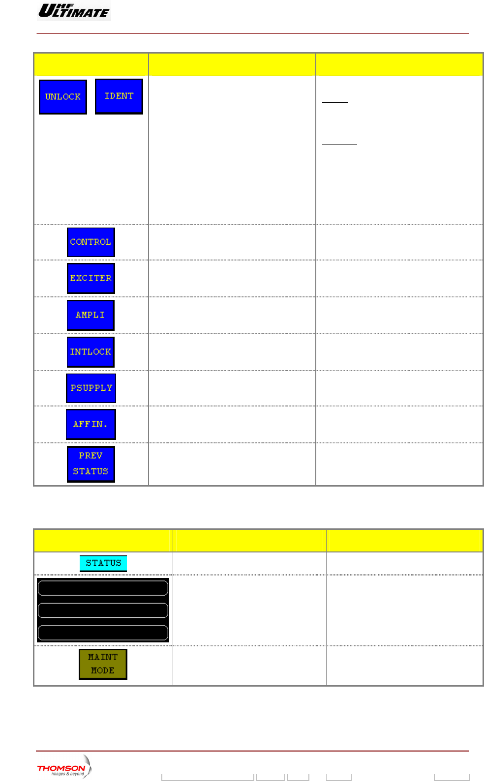
CONTROL KEYS FUNCTIONS DISPLAY/COMMENTS
/
or the "IDENTIFICATION" window. IDENT
Calls up the "NUMERICAL VALUE" window PASS / IDENT
: The "IDENTIFICATION" window
displays software references for the screen
and CPU card ; this function is available
when the touch screen is unlocked.
UNLOCK : Operation is realized in
accordance with your installation choice
(PASS LE)
♦ Pressing this control Key, the PCL is
automatically unlocked or,
♦ A password can be entered using the
"NUMERICAL VALUE" window while the
PCL is unlocked.
WORD DISABLE, or ENAB
Calls up the "CONTOL Level 1" window.
Calls up the "EXCITER Level 1" window.
Calls up the "AMPLIFIERS" window. . (a)
Calls up the "INTLOCK" window. . (a)
Calls up the "POWER SUPPLY" window. (a)
Calls up the "AFFINITY" window. (b)
Calls up the "TRANSMITTER STATUS"
window.
(a): Not Visib for AFFINIT
(b): Not Visible for OPTIMU
le Y family
M or ULTIMATE families
MESSA E GFUNCTIONS DISPLAY/COMMENTS
Gives the window name.
Last indicated faults. This window displays the last three faults
which have been indicated.
Displays the g mode of
the transmitter
normal mode).
MAINT MO
Blinking message to indicate that the
maintenance mode is operating
current operatin
(maintenance mode or
DE / NORMAL MODE
9932 V2
45321648.01 108 B E Checked 62 / 192
Numéro / Number Doc. Rev. Lan
g
u. 27/06/2006 Pa
g
e
Digital Liquid Cooled UHF
TV Equipment
Use of commands and description of indicators
Information contained is this document is confidential, is THOMSON property and cannot be disclosed in whatever form without prior written authorization of THOMSON.
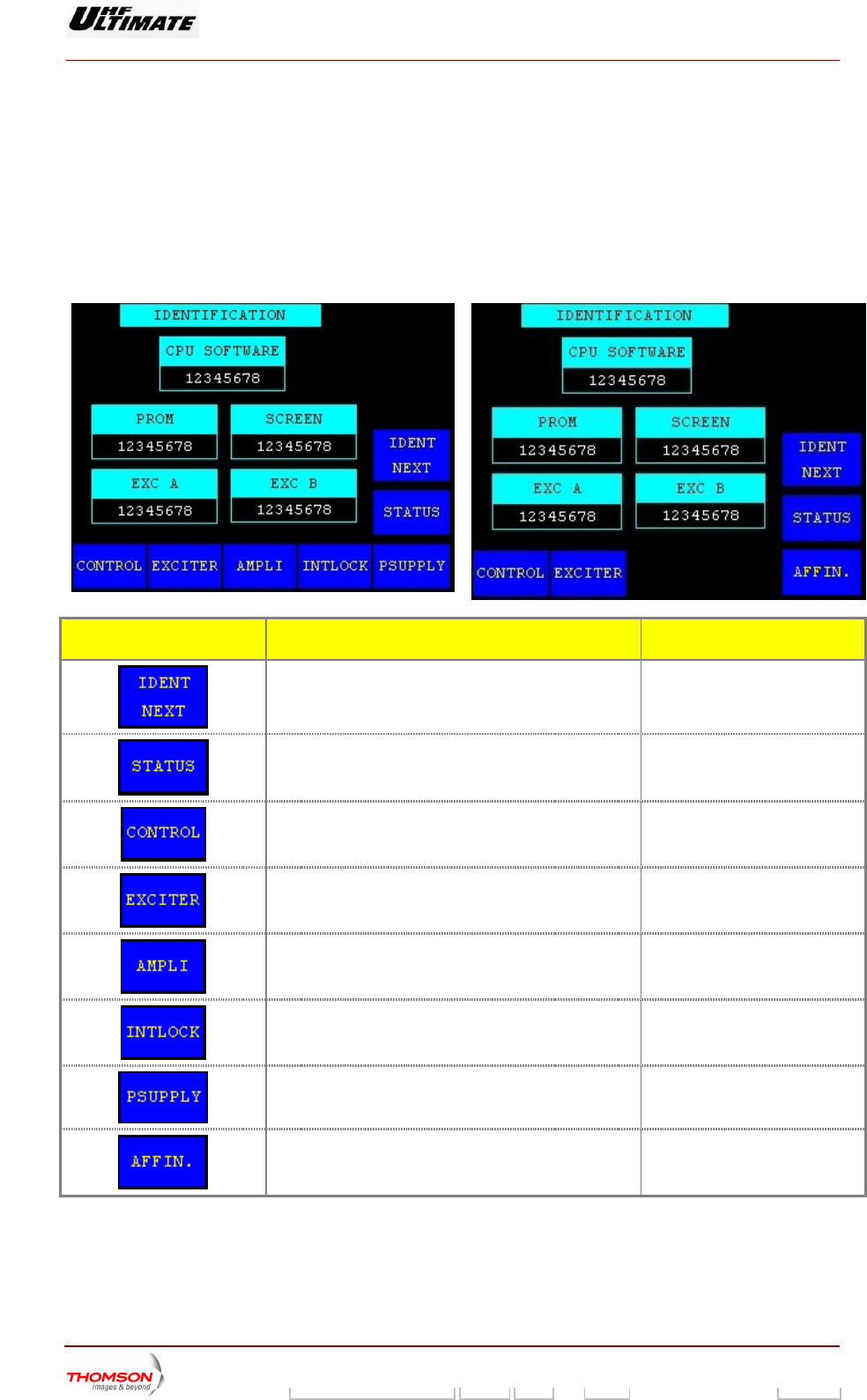
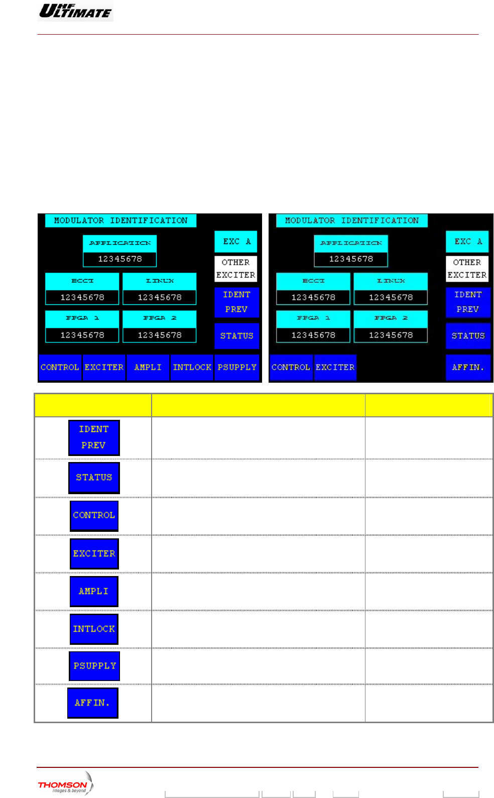
2.1.6. "IDENTIFICATION" window
This window is called up b eys in the "STATUS" window. This window
is only accessible when th / CMD LOCKED” control
keys in the “STATUS” wind
It displays software references for the touch screens, the CPU card and EXCITER units.
OPTIMUM FAMILY OR
y pressing the "IDENT" control k
e touch screen is unlocked with the “LOCK CM
ow.
D
ULTIMATE FAMILY AFFINTY FAMILY
CONTROL KEYS FUNCTIONS DISPLAY/COMMENTS
Calls up the "MODULATOR IDENTIFICATION" window.
Calls up the "STATUS" window.
Calls up the "CONTROL Level 1" window.
Calls up the "EXCITER Level 1" window.
Calls up the "AMPLIFIERS" window. . (a)
Calls up the «INTERLOCK» window . (a)
Calls up the "POWER SUPPLY" window. . (a)
Calls up the "AFFINITY" window. (b)
(a): Not Visible for AFFINITY family
(b): Not Visible for OPTIMUM or ULTIMATE families
9932 V2
45321648.01 108 B E Checked 63 / 192
Numéro / Number Doc. Rev. Lan
g
u. 27/06/2006 Pa
g
e
Digital Liquid Cooled UHF
TV Equipment
Use of commands and description of indicators
Information contained is this document is confidential, is THOMSON property and cannot be disclosed in whatever form without prior written authorization of THOMSON.
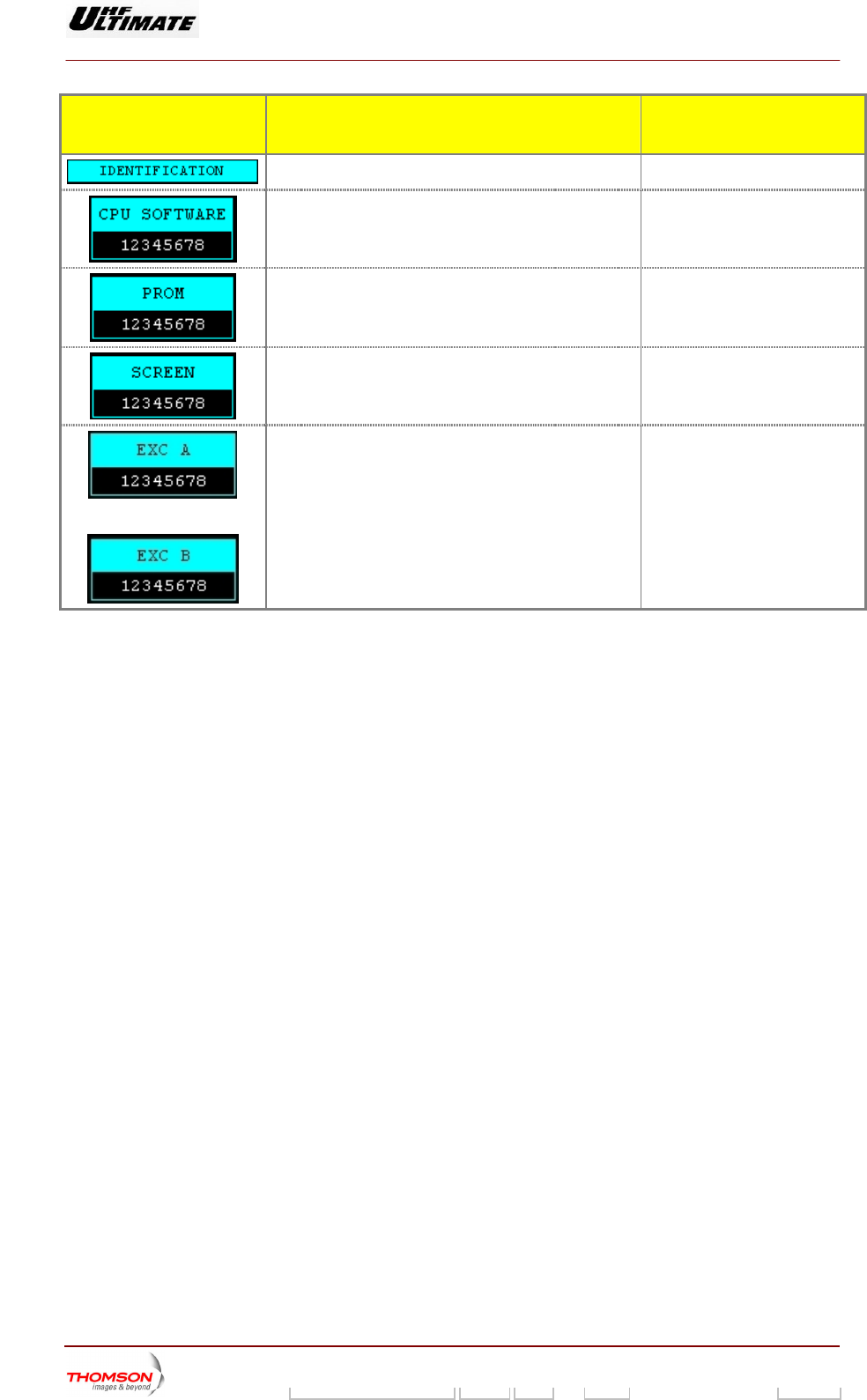
INDICATOR LAMPS AND
MESS GE DISPLAYS A
FUNCTIONS DISPLAY/COMMENTS
Gives the window name.
Displays the reference of the CPU board software.
Displays the reference of the CPU board. PROM
software
Displays the reference of the touch screen an
software.
d its
Displays the reference of the Main software for exciter A. ♦ Digital Transmitter, MODAP
Version only:
With oldest DAP software this
message displays could be
absent
Displays the reference of the Main software for exciter B.
(*)
♦ Analogue Transmitter
With the analogue driver, this
message displays is not used
(*) : Only in Double Drive Version
9932 V2
45321648.01 108 B E Checked 64 / 192
Numéro / Number Doc. Rev. Lan
g
u. 27/06/2006 Pa
g
e
Digital Liquid Cooled UHF
TV Equipment
Use of commands and description of indicators
Information contained is this document is confidential, is THOMSON property and cannot be disclosed in whatever form without prior written authorization of THOMSON.
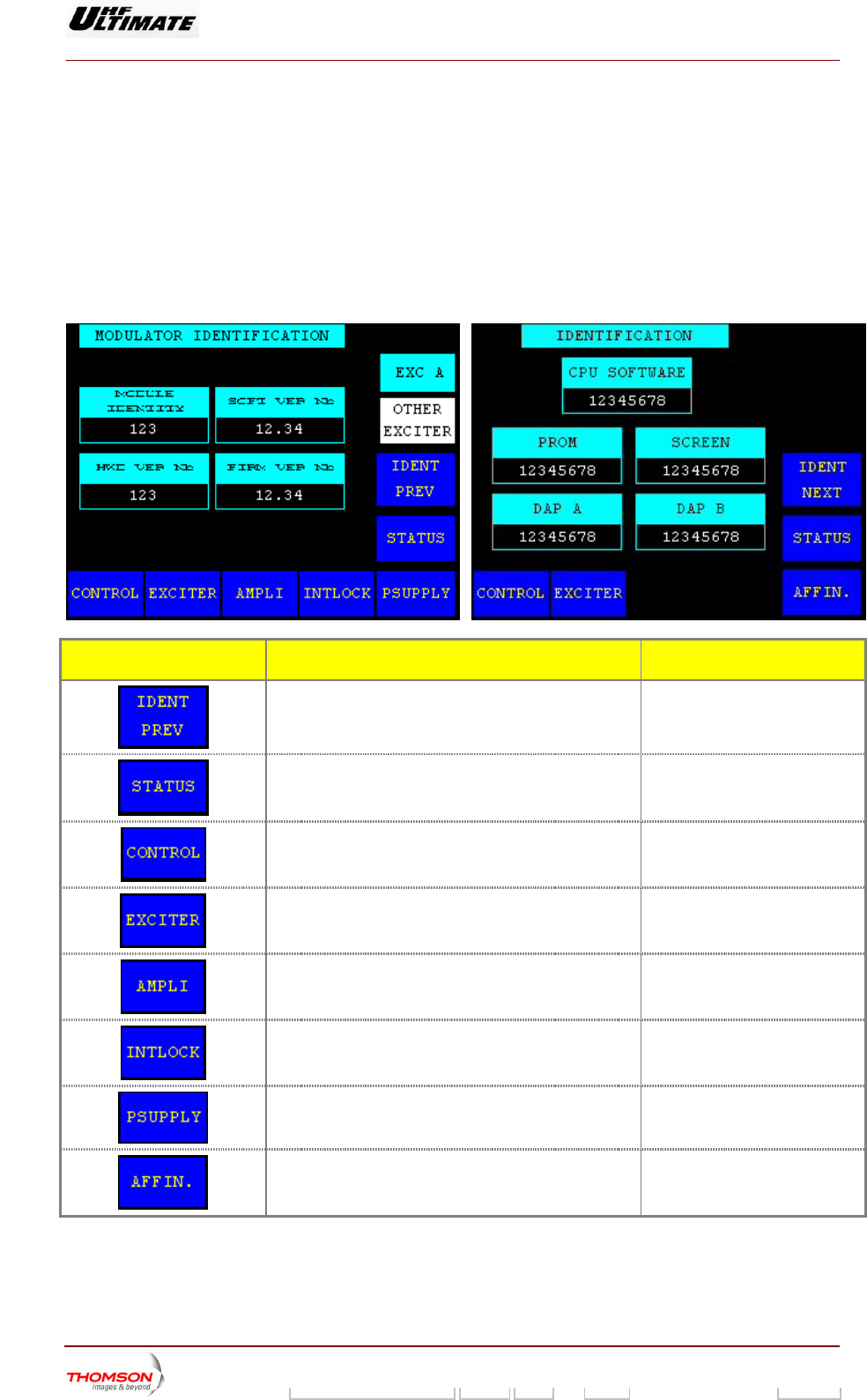
2 FICATION, Type I" window
This window is called up " control keys he "IDENTIFICATION"
window. It is only accessible when the touch screen is unlocked with the “LOCK CMD / CMD
LOCKED” control keys in the “STATUS” window.
This window displays so r the MODULATOR unit. It is only available with
TANGBERG MODULATOR
OPTIMUM FAMILY OR ULTIMATE FAMILY
.1.7. "MODULATOR IDENTI
by pressing the "IDENT NEXT in t
ftware references fo
unit (MODAP version only).
AFFINTY FAMILY
CONTROL KEYS FUNCTIONS DISPLAY/COMMENTS
Calls up the "IDENTIFICATION" window.
Calls up the "STATUS" window.
Calls up the "CONTROL Level 1" window.
Calls up the "EXCITER Level 1" window.
Calls up the "AMPLIFIERS" window. (a)
Calls up the «INTERLOCK» window (a)
Calls up the "POWER SUPPLY" window. (a)
Calls up the "AFFINITY" window. (b)
(a): Not Visible for AFFINITY family
(b): Not Visible for OPTIMUM or ULTIMATE families
9932 V2
45321648.01 108 B E Checked 65 / 192
Numéro / Number Doc. Rev. Lan
g
u. 27/06/2006 Pa
g
e
Digital Liquid Cooled UHF
TV Equipment
Use of commands and description of indicators
Information contained is this document is confidential, is THOMSON property and cannot be disclosed in whatever form without prior written authorization of THOMSON.
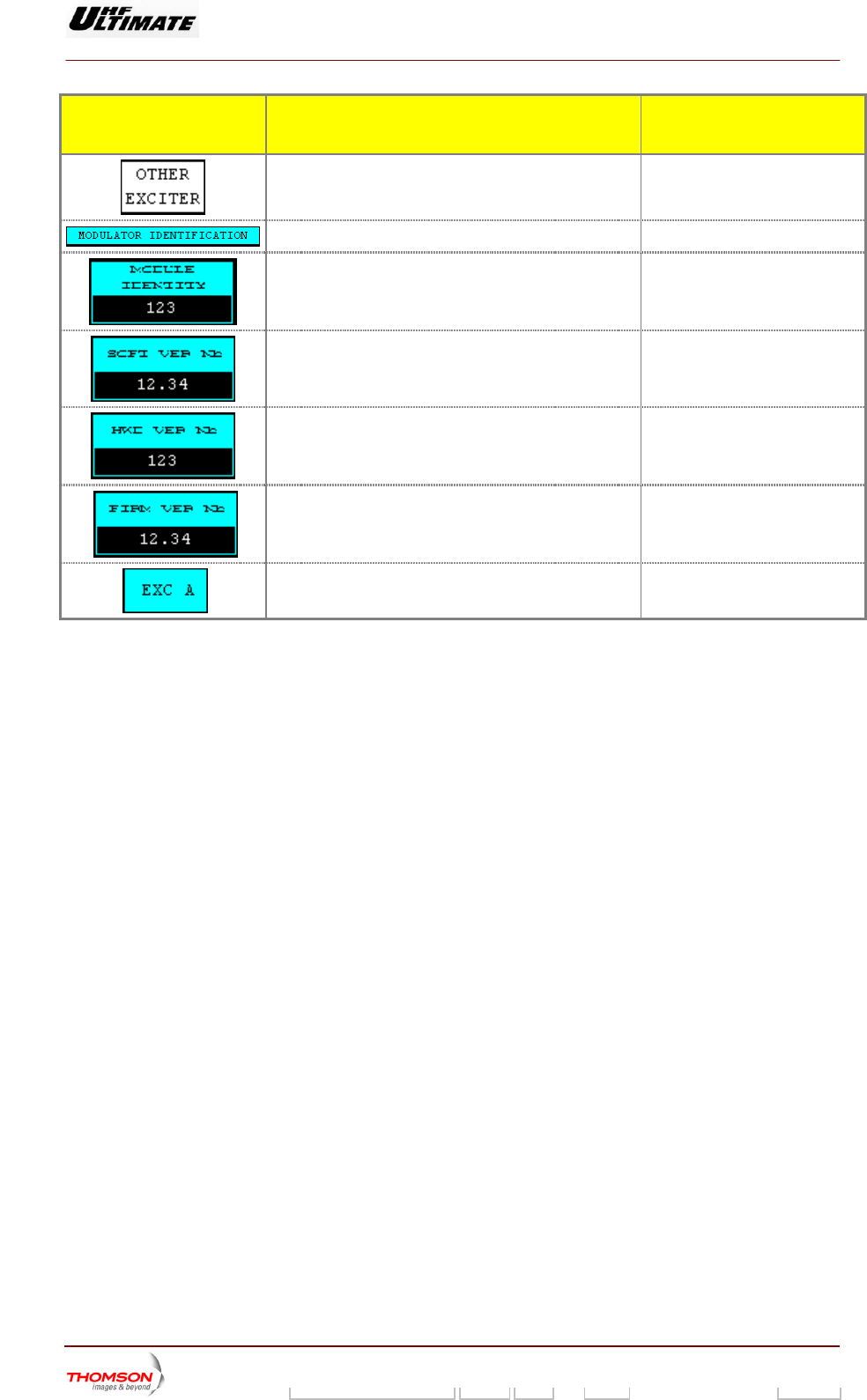
INDICATOR LAMPS AND
MESS GE DISPLAYS A
FUNCTIONS DISPLAY/COMMENTS
Calls up data from the other exciter. (*)
Gives the window name.
Displays the ID number of the module.
Displays the reference of the Internal COFDM
MODULATOR software.
Displays the reference of the internal COFDM
MODULATOR hardware.
Displays the reference of the internal COFDM
MODULATOR firmware
.
Indicates w xciter data are displayed. (*) EXC A / EXC B
hich e
(*) : Only in Double Drive Version
9932 V2
45321648.01 108 B E Checked 66 / 192
Numéro / Number Doc. Rev. Lan
g
u. 27/06/2006 Pa
g
e
Digital Liquid Cooled UHF
TV Equipment
Use of commands and description of indicators
Information contained is this document is confidential, is THOMSON property and cannot be disclosed in whatever form without prior written authorization of THOMSON.
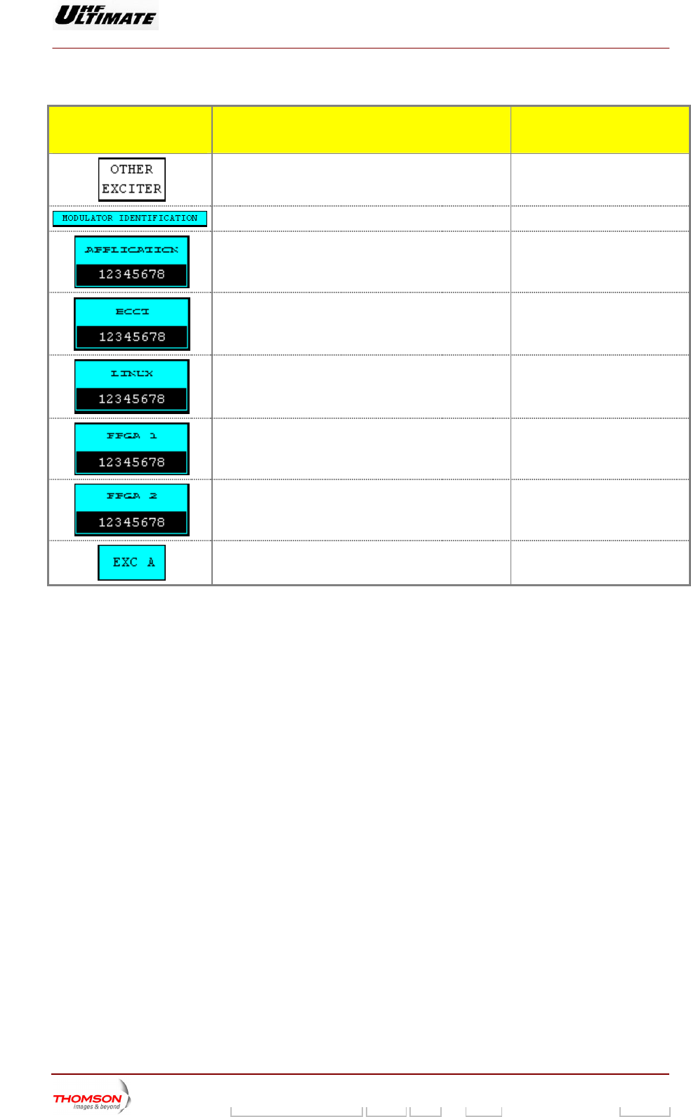
2.1.8. "MODULATOR IDENTIFICATION, type II" window
This window is called up by pressing the "IDENT NEXT" con
window. It is only accessible when the touch screen is unlo
LOCKED” co s in the “STAT
This window displays sof references for the type II MODULATOR unit or for the SIRIUS
It is only available with
MODULATOR unit.
R ULTIMATE FAMILY
trol keys in the "IDENTIFICATION"
cked with the “LOCK CMD / CMD
ntrol key US” window.
tware
MODULATOR unit.
type II MODULATOR unit “ACBB” (MODAP version) or with SIRIUS
OPTIMUM FAMILY OAFFINTY FAMILY
CONTROL KEYS FUNCTIONS DISPLAY/COMMENTS
Calls up the "IDENTIFICATION" window.
Calls up the "STATUS" window.
Calls up the "CONTROL Level 1" window.
Calls up the
"EXCITER Level 1" window.
Calls up the "AMPLIFIERS" window. (a)
Calls up the «INTERLOCK» window . (a)
Calls up the "POWER SUPPLY" window. (a)
Calls up the "AFFINITY" window. (b)
(a): Not Visible for AFFINITY family
9932 V2
45321648.01 108 B E Checked 67 / 192
Numéro / Number Doc. Rev. Lan
g
u. 27/06/2006 Pa
g
e
Digital Liquid Cooled UHF
TV Equipment
Use of commands and description of indicators
Information contained is this document is confidential, is THOMSON property and cannot be disclosed in whatever form without prior written authorization of THOMSON.
(b): Not Visi ULTIM
. (a)
ble for OPTIMUM or ATE families
INDICATOR L MPS AND A
MESSAGE DISPLAYS
FUNCTIONS DISPLAY/COMMENTS
Calls up data from the other exciter. (*)
Gives the window name.
Displays the reference of the internal COFD
MODULATOR software.
M ACBB
Displays the reference of the Boot software.
Displays the reference of the LINUX software.
Displays the reference of the FPGA 1software.
Displays the reference of the FPGA 2 software.
Indicates which exciter data are displayed. (*) EXC A / EXC B
(*) : Only in Double Drive Version
9932 V2
45321648.01 108 B E Checked 68 / 192
Numéro / Number Doc. Rev. Lan
g
u. 27/06/2006 Pa
g
e
Digital Liquid Cooled UHF
TV Equipment
Use of commands and description of indicators
Information contained is this document is confidential, is THOMSON property and cannot be disclosed in whatever form without prior written authorization of THOMSON.
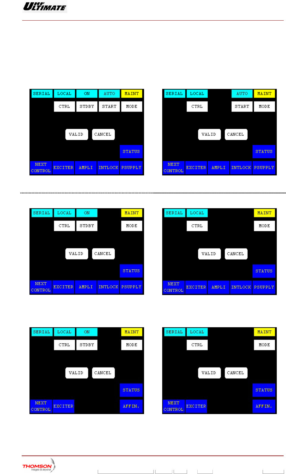
2.1.9. "CONTROL Level 1" window
From other windows it can be called up by pressing the "CONTROL" key.
This window contains the commands available in maintenance mode and normal mode.
OR OPTIMUM FAMILY ULTIMATE FAMILY – ANALOG TRANSMITTER
Figure 14: Dual Drive Transmitter
Figure 15: Single Drive Transmitter
OPTIMUM FAMILY OR ULTIMATE FAMILY – DIGITAL TRANSMITTER
Figure 16: Dual Drive Transmitter
Figure 17: Single Drive Transmitter
TER AFFINTY FAMILY – DIGITAL TRANSMIT
Figure 18: Dual Drive Transmitter Figure 19: Single Drive Transmitter
9932 V2
45321648.01 108 B E Checked 69 / 192
Numéro / Number Doc. Rev. Lan
g
u. 27/06/2006 Pa
g
e
Digital Liquid Cooled UHF
TV Equipment
Use of commands and description of indicators
Information contained is this document is confidential, is THOMSON property and cannot be disclosed in whatever form without prior written authorization of THOMSON.
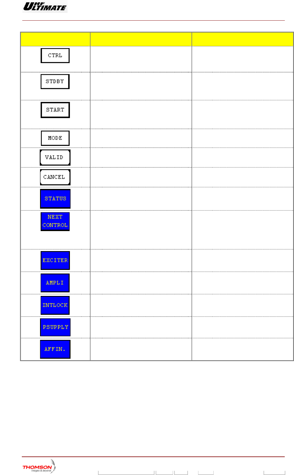
CONTROL KEYS FUNCTIONS DISPLAY/COMMENTS
Selects local or remote user interface. T
he command is not available if the PCL is
locked. Selecting remote user interface locks
the following control keyss: CTRL, STDBY,
MODE, EXCITER
Only in Double Drive Version
hile the PCL is
cked (disabled).
Initiates shutdown or start-up of the reserve
exciter.
Command is disabled w
lo
Only in Analogue Transmitter
ing
mode (manual or automatic)
ommand is disabled while the PCL is
locked (disabled)
Selects the transmitter on-air/off-air switch C
Selects the transmitter-operating
(maintenance or normal).
mode ommand is disabled while the PCL is
cked (disabled).
C
lo
Validates a
selection.
Cancels a sele
ction.
Calls up the STATUS" "TRANSMITTER
window.
Calls up windows as follows:
"CONTROL MAINT Level 2", if the system is
in maintenance mode,
"CONTROL OPER Level 2", if the system is
in normal mode.
Calls up the "EXCITER Level 1" window.
Calls up the "AMPLIFIERS" window. (a)
Calls up the "INTLOCK" window. (a)
Calls up the "POWER SUPPLY" window. (a)
Calls up the "AFFINITY" window. (b)
(a): Not Visible for AFFINITY family
(b): Not Visible for OPTIMUM or ULTIMATE families
9932 V2
45321648.01 108 B E Checked 70 / 192
Numéro / Number Doc. Rev. Lan
g
u. 27/06/2006 Pa
g
e
Digital Liquid Cooled UHF
TV Equipment
Use of commands and description of indicators
Information contained is this document is confidential, is THOMSON property and cannot be disclosed in whatever form without prior written authorization of THOMSON.
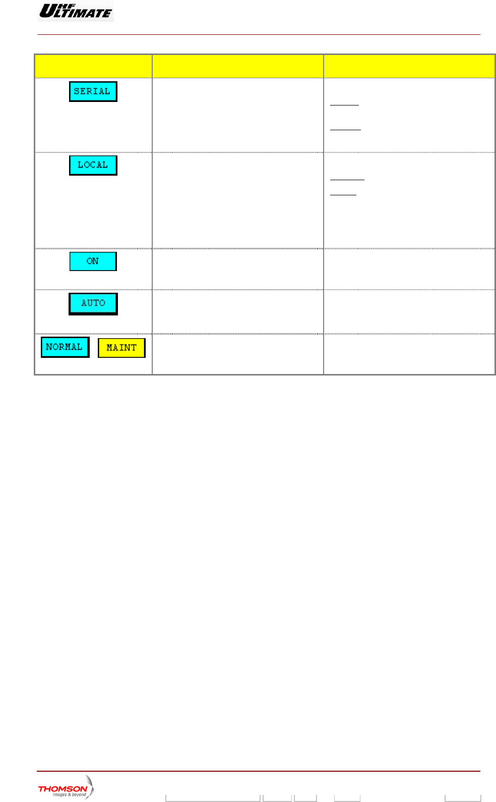
MESSAGE FUNCTIONS DISPLAY/COMMENTS
the transmitter. SERIAL
Displays the current remote control mode of SERIAL / PARALL
: Remote control through a
RS432/485 serial link.
PARALL (Remote controls and indicat
Remote control through hard
ors):
wired
connections.
Displays the selected user interface. RE
REMOTE
MOTE / LOCAL
: Indicates a remote user interface.
LOCAL : Indicates Local Control Panel.
Only commands from the selected user
interface will be operative.
Flashes until the "CTRL" command is either
validated or cleared.
Only in Double Drive Version
Displays the status (on or off) of the reserve
exciter.
OFF / ON
Flashes until the "STDBY" command is
either validated or cleared.
Only in Analogue Transmitter
Displays the on-air/off-air switching mode
selected
MANUAL, AUTO
Flashes until the «START» command is
either validated or cleared
Displays the current operating mode of the
transmitter (maintenance mode or normal
mode).
NORMAL / MAINT
Flashes s either
validated
/ until the "MODE" command i
or cleared.
9932 V2
45321648.01 108 B E Checked 71 / 192
Numéro / Number Doc. Rev. Lan
g
u. 27/06/2006 Pa
g
e
Digital Liquid Cooled UHF
TV Equipment
Use of commands and description of indicators
Information contained is this document is confidential, is THOMSON property and cannot be disclosed in whatever form without prior written authorization of THOMSON.
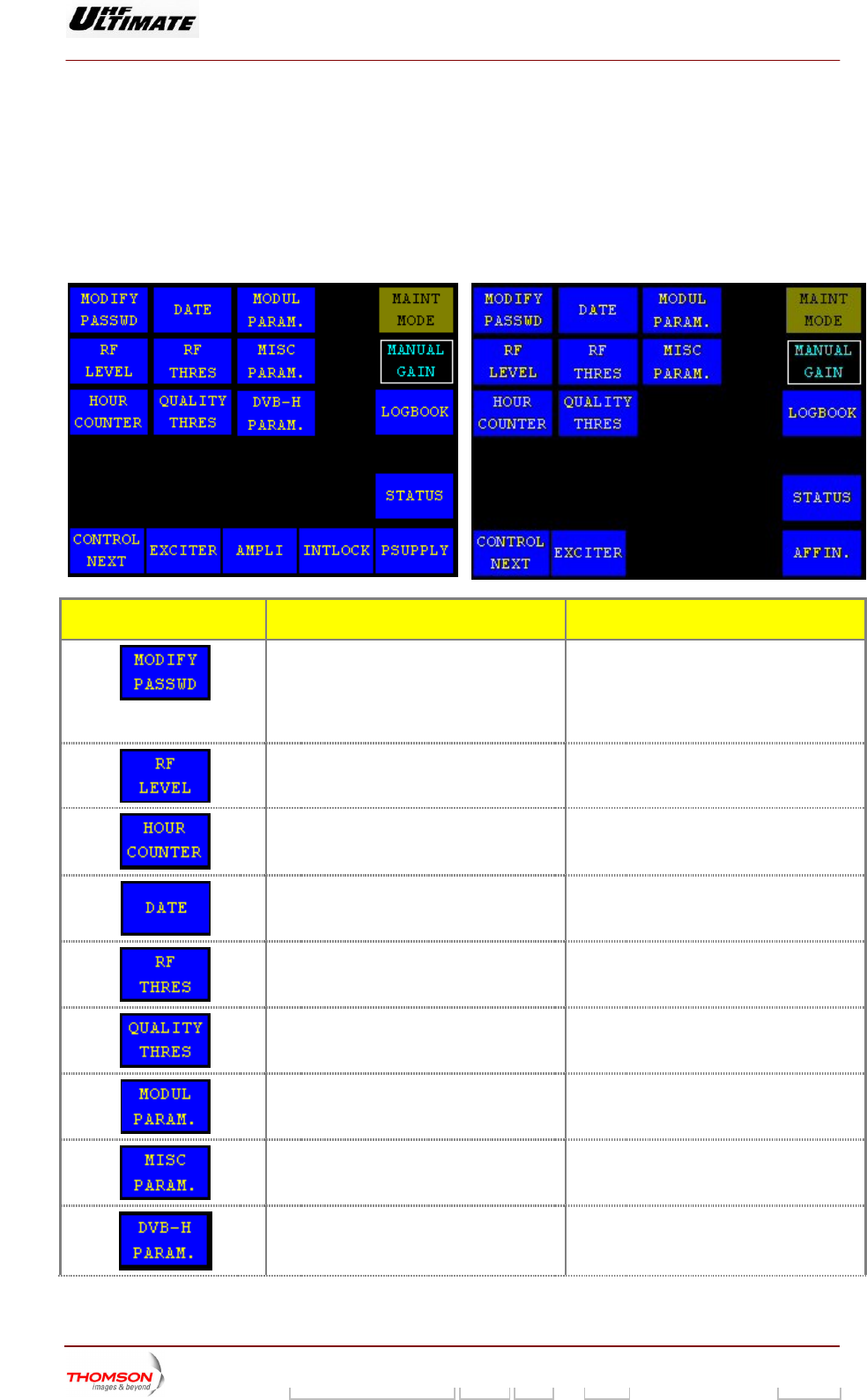
2.1.10. "CONTROL MAINT Level 2" window for Maintenance mode
This window is called up b " control keys in the "CONTROL Level 1"
window while the transmitter is in mai
It provides access to commands and information which are only available in maintenance mode.
OPTIMUM FAMILY OR ULTIMATE FAMILY
y pressing the "NEXT CONTROL
ntenance mode.
AFFINTY FAMILY
CONTROL KEYS FUNCTIONS DISPLAY/COMMENTS
Calls up the "MODIFY PASSWORD" window ccording to
(PASSWORD
ontrol key visible in selection
« PASSWORD ENABLE » only.
(for changing the password).
This control key is available a
your installation choice
DISABLE, ENABLE)
C
Calls up the "RF LEVEL" window.
Calls up the "HOUR COUNTER" window.
Calls up the "DATE & TIME" window.
Calls up the "RF THRESHOLD" window.
Calls up the "QUALITY THRESHOLD
SETTINGS" window.
Calls up the "MODULATOR PARAMETERS"
window.
Calls up the "MISCELLANEOUS" window.
Calls up the "DVB-H MODULATOR
PARAMETERS" window.. (1)
The control key is according to your
installation mode
9932 V2
45321648.01 108 B E Checked 72 / 192
Numéro / Number Doc. Rev. Lan
g
u. 27/06/2006 Pa
g
e
Digital Liquid Cooled UHF
TV Equipment
Use of commands and description of indicators
Information contained is this document is confidential, is THOMSON property and cannot be disclosed in whatever form without prior written authorization of THOMSON.
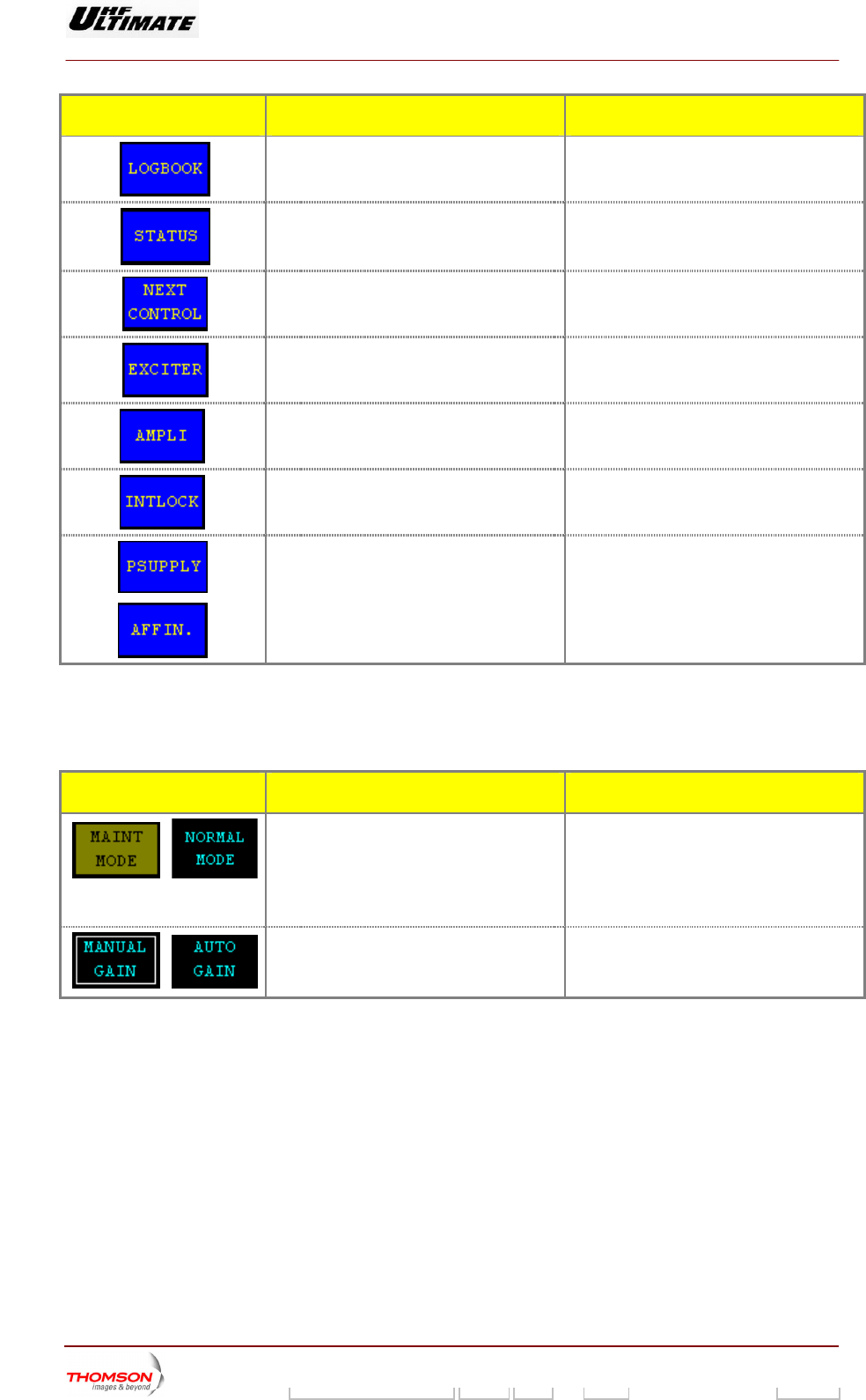
CONTROL KEYS FUNCTIONS DISPLAY/COMMENTS
Calls up the "LOGBOOK" window.
Calls up the "TRANSMITTER STATUS"
window.
Calls up the "CONTROL MAINT Level 3"
window.
Calls up the "EXCITER Level 1" window.
Calls up the "AMPLIFIERS" window. (a)
Calls up the «INTERLOCK» window (a)
Calls up the "POWER SUPPLY" window. (a)
Calls up the "AFFINITY" window. (b)
(a): INITY family
(b): Not Visible for OPTIMUM or
(1): Visible for DVB-H trans
Not Visible for AFF
ULTIMATE families
mitter only
MESSAGE FUNCTIONS DISPLAY/COMMENTS
/
Displays the current operating mode of the
transmitter (maintenance mode or normal
mo
The "MAINT MODE" message window must
be displayed.
de).
Blinking message to indicate that the
maintenance mode is operating
Displays, which gain control mode (manual
or automatic), is currently picked up by the
MANUAL GAIN / AUTO GAIN
transmitter.
/
9932 V2
45321648.01 108 B E Checked 73 / 192
Numéro / Number Doc. Rev. Lan
g
u. 27/06/2006 Pa
g
e
Digital Liquid Cooled UHF
TV Equipment
Use of commands and description of indicators
Information contained is this document is confidential, is THOMSON property and cannot be disclosed in whatever form without prior written authorization of THOMSON.
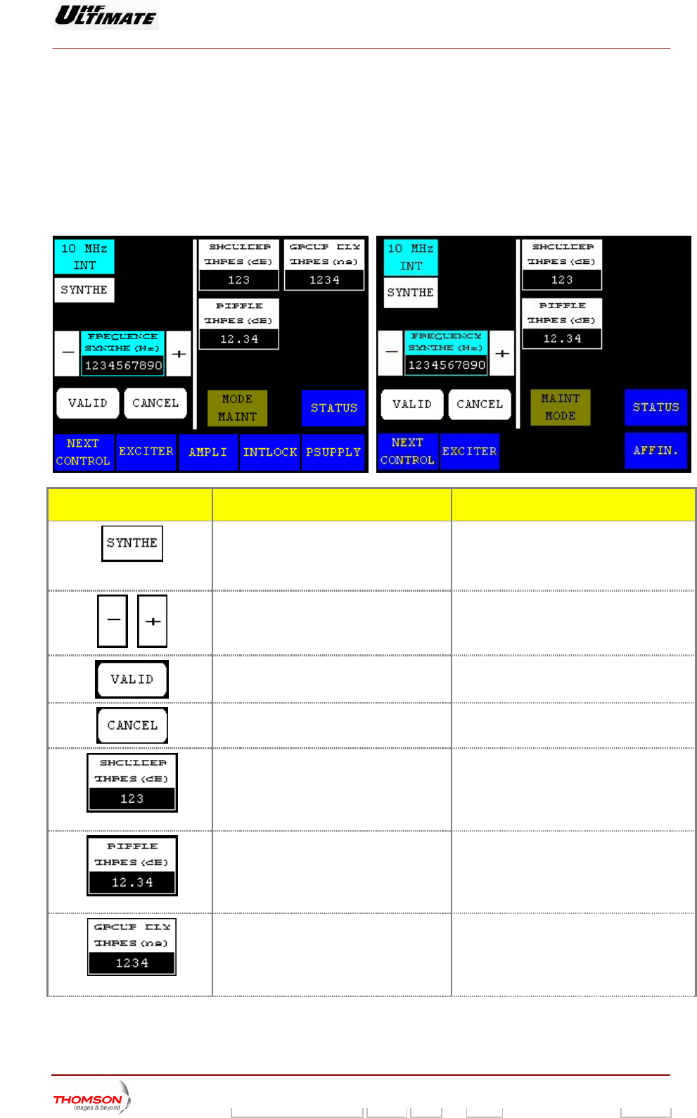
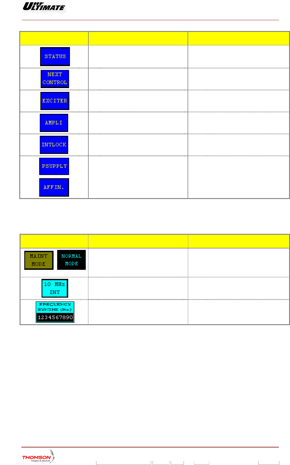
2.1.11. "CONTROL MAINT Level 3" window for Maintenance mode
This window is called up by pressing the "NEXT CONTROL" control keys in the "CONTROL MAINT
Level 2" window while the transmitter is in maintenance mode.
It provides ac ss to comm a intenance mode.
OPTIMUM FAMILY OR ULTIMATE FAMILY
ce ands and information which are only vailable in ma
AFFINTY FAMILY
CONTROL KEYS FUNCTIONS DISPLAY/COMMENTS
Selects the RF synthesiser alarm mode.
Toggles between 10 MHz INT and 10MHz
EXT
command is
either validated or cleared.
Commands are disabled while the PCL is
locked (disabled).
Flashes until the "SYNTHE"
/
Increments or decrements RF synthesiser
frequency value.
Control keys are only invisible in SFN mode
operation.
Validates a selection.
Cancels a selection.
Calls up the "NUMERICAL VALUE" window
in which the shoulder threshold beyond
which the exciter performs a correction can
be changed.
Displays last selection.
Calls up the “NUMERICAL VALUE” window
in which the ripple threshold beyond which
the exciter performs a correction can be
changed.
Displays last selection.
Calls up the “NUMERICAL VALUE” window
in which the group delay threshold beyond
which the exciter performs a correction can
be changed. (3)
Displays last selection.
9932 V2
45321648.01 108 B E Checked 74 / 192
Numéro / Number Doc. Rev. Lan
g
u. 27/06/2006 Pa
g
e
Digital Liquid Cooled UHF
TV Equipment
Use of commands and description of indicators
Information contained is this document is confidential, is THOMSON property and cannot be disclosed in whatever form without prior written authorization of THOMSON.
CONTROL KEYS FUNCTIONS DISPLAY/COMMENTS
window.
Calls up the "TRANSMITTER STATUS"
Calls up the "CONTROL Level 4" window.
Calls up the "EXCITER
Level 1" window.
Calls up the "AMPLIFIERS" window. (a)
Calls up the «INTERLOCK» window (a)
Calls up the "POWER SUPPLY" window. (a)
Calls up the "AFFINITY" window. (b)
(a): Not Visible for AFFINITY family
(b): TIMUM or ULTIM
(3): MediaFLO modulator o
Not Visible for OP ATE families
nly
MESS GEA FUNCTIONS DISPLAY/COMMENTS
/
al
mode).
ORMAL MODE" message window
ust be displayed.
Blinking message to indicate that the
maintenance mode is operating
Displays the current operating mode of the
transmitter (maintenance mode or norm
The "M
m
Displays the RF synthesiser alarm mode. 1
0 MHz INT, 10 MHz EXT
Displays the RF synthesiser frequency value.
9932 V2
45321648.01 108 B E Checked 75 / 192
Numéro / Number Doc. Rev. Lan
g
u. 27/06/2006 Pa
g
e
Digital Liquid Cooled UHF
TV Equipment
Use of commands and description of indicators
Information contained is this document is confidential, is THOMSON property and cannot be disclosed in whatever form without prior written authorization of THOMSON.
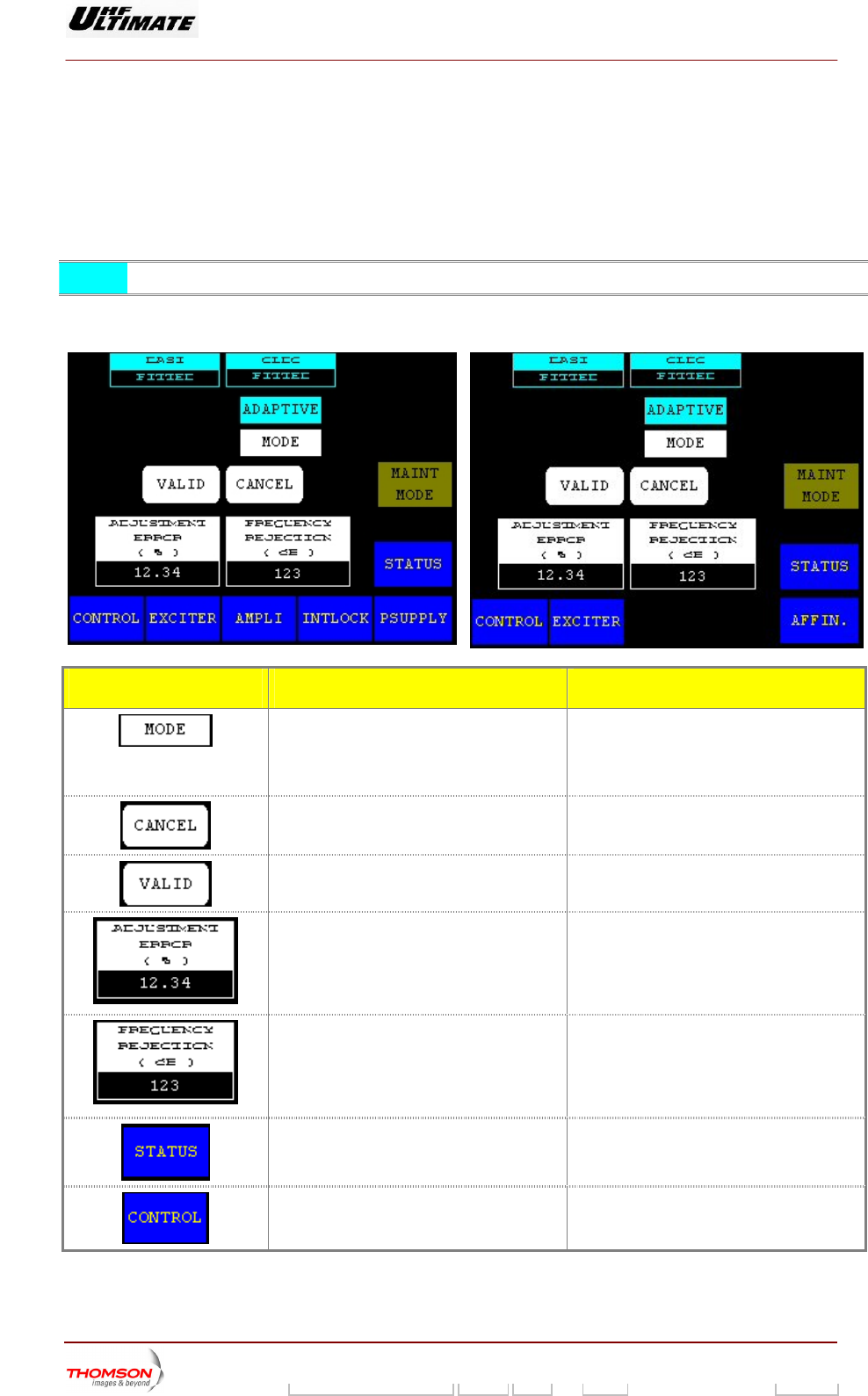
2.1.12. "CONTROL MAINT Level 4" window for Maintenance mode (MODAP version
ONLY)
This window is ll d up b e "CONTROL NEXT" co
Level 3" window while the transmitter is in maintenance mode.
It provides access to comm ode.
ca e y pressing th ntrol keys in the "CONTROL MAINT
ands and information which are only available in maintenance m
NOTE: This wi o s is a DM MODAP version only. nd w vailable in COF
OPTIMUM FAMILY OR ULTIMATE FAMILY AFFINTY FAMILY
CONTROL KEYS FUNCTIONS DISPLAY/COMMENTS
Selects the type of correction performed by
the OLDC card (Fixed or Adaptive).
Command is disabled while the PCL is
locked (disabled).
In fixed position, the OLDC correction
parameters are not continuously adjusted.
Cancels a selection.
Validates a selection.
Calls up the "NUMERICAL VALUE" window
in which the I/Q amplitude error threshold
beyond which the OLDC card performs a
correction can be changed.
Displays last selection.
Command is disabled while the PCL is
locked (disabled).
Calls up the "NUMERICAL VALUE" window
in which the central frequency rejection
threshold beyond which the OLDC card
performs a correction can be changed.
Displays last selection.
Command is disabled while the PCL is
locked (disabled).
Calls up the "TRANSMITTER STATUS"
window.
Calls up the "CONTROL Level 1" window.
9932 V2
45321648.01 108 B E Checked 76 / 192
Numéro / Number Doc. Rev. Lan
g
u. 27/06/2006 Pa
g
e
Digital Liquid Cooled UHF
TV Equipment
Use of commands and description of indicators
Information contained is this document is confidential, is THOMSON property and cannot be disclosed in whatever form without prior written authorization of THOMSON.
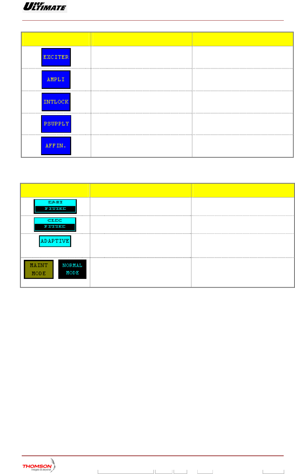
CONTROL KEYS FUNCTIONS DISPLAY/COMMENTS
Calls up the "EXCITER L
evel 1" window.
Calls up the "AMPLIFIERS" window. (a)
Calls up the «INTERLOCK» window (a)
Calls up the "POWER SUPPLY" window. (a)
Calls up the "AFFINITY" window. (b)
(a): Not Visible for AFFINITY family
(b): Not Visible for OPTIMUM or ULTIMATE families
MESSAGE FUNCTIONS DISPLAY/COMMENTS
Displays whether a Double ASI input is
present or absent in the MODAP unit.
DASI NOT FITTED / DASI FITTED
Displays w unit is present or
absent.
OLDC ED hether an OLDC FITTED / OLDC NOT FITT
Displays the type of correction (fixed
adaptive) performed b
or
y the OLDC unit.
ADAPTIVE / FIXED
In fixed position, the OLDC correction
parameters are not continuously adjusted.
Displays last selection.
Displays the cu
/
rrent operating mode of the
transmitter (maintenance mode or normal
mode).
The "MAINT MODE" message window must
be displayed.
Blinking message to indicate that the
maintenance mode is operating
9932 V2
45321648.01 108 B E Checked 77 / 192
Numéro / Number Doc. Rev. Lan
g
u. 27/06/2006 Pa
g
e