Thomson Broadcast and Multimedia ULT-1K10K2 UHF Digital transmitter, for use with MediaFlo User Manual PREIMPAP
Thomson Broadcast & Multimedia, Inc. UHF Digital transmitter, for use with MediaFlo PREIMPAP
Contents
User Manual part 4
Digital Liquid Cooled UHF
TV Equipment
Use of commands and description of indicators
Information contained is this document is confidential, is THOMSON property and cannot be disclosed in whatever form without prior written authorization of THOMSON.
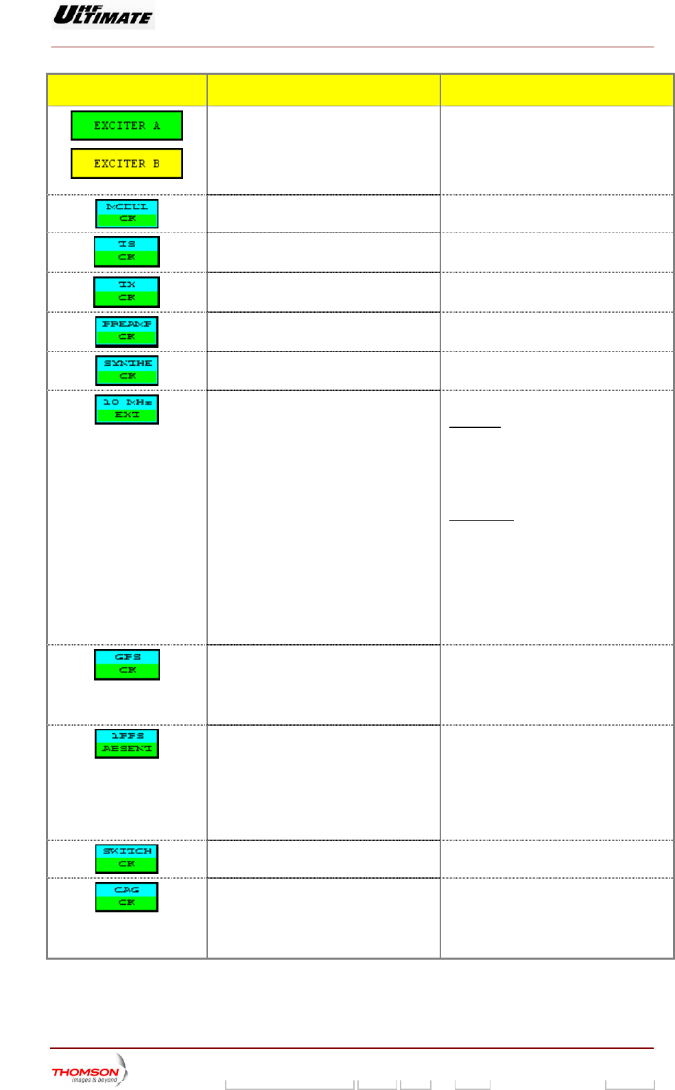
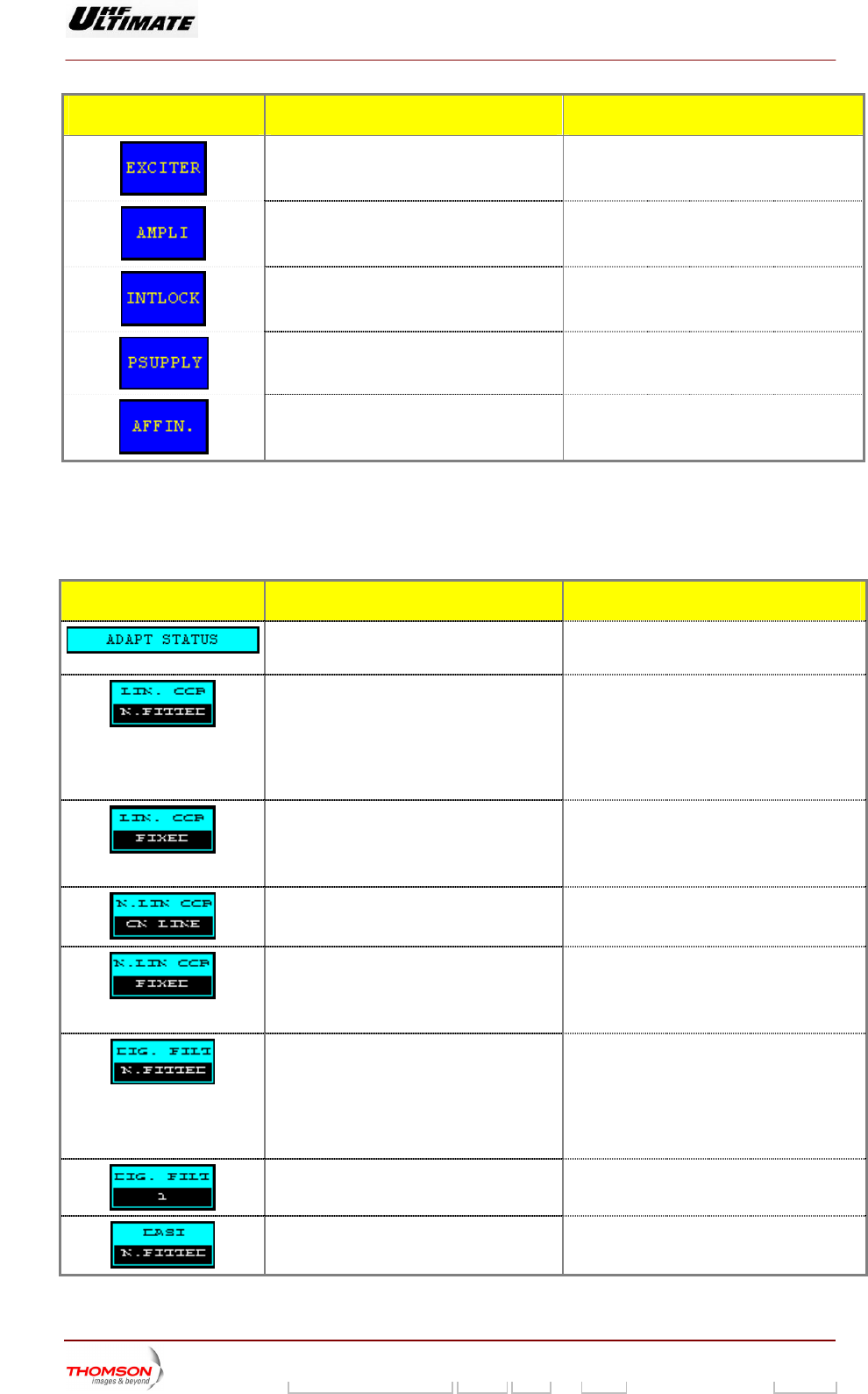
MESSAGE FUNCTIONS DISPL S AY/COMMENT
Shows the double column of the relevant
exci
Indicates which exciter is selected and which
is on-air, as well as the status (fault-free or
fault
EXCITER A / EXCITER B
Message is displayed on green background:
Exciter selected
Message is displayed on yellow background:
xc r non selected
ter. (*)
y) of both exciters (1). E ite
Indi
modulator.
MODULAT OK / MODULAT FAULT (1) cates the overall status of the COFDM
Indicates the overall status of the TS card. TS OK / TS FAULT / TS MISSING (1)
Indicates the overall status of the TX card. TX OK / TX FAULT / TX MISSING (1)
Indicates the overall status of the
prea
PREAMP OK / PREAMP FAULT (1)
mplifier.
In
sy
dicates the overall status of the RF
nthesiser.
SYNTHE OK / SYNTHE FAULT (1)
Indicates the status of the 10 MHz drive
oscillator.
10 MHz EXT / 10 MHz INT
First case: "10 MHz INT" control keys in
"INSTALLATION PARAMETERS Level 1"
window is selected.
♦ A status message (10 MHz ext or 10 MHz
INT) is displayed in normal video (on
black background).
Second case: "10 MHz EXT" control keys in
"INSTALLATION PARAMETERS Level 1"
window is selected.
♦ A status message (10 MHz EXT) is
displayed in normal video (on black
background).
♦ A fault message (10 MHz INT) is
displayed in reverse video (on white
background).
Indicates the overall status of the GPS
receiver card.
GPS OK / GPS FAULT/ GPS MISSING /
NOT VISIBLE (1)
The “GPS” key in “EXCITER” window is not
available (not visible) when the optional card
is not present.
Indicates the presence or absent of the
1PPS.
1PPS ABSENT / 1PPS PRESENT
♦ Operation mode used: “INTERNAL GPS”
The signal status is delivered from
internal GPS card.
♦ Operation mode used: “EXTERNAL GPS”
The signal status is coming from 1PPS
input signal.
Indicates the overall status of the SWITCH
ALE card.
SWITCH OK / SWITCH FAULT (1)
Indicates the status of the AGC loop AGC OK / AGC FAULT (1)
FAULT: The AGC voltage is out of the
operation range: +- 2dB (0,5 to 2,5V)
regarding AGC reference. It’s displays in
“AGC SETTING” screen.
9932 V2
45321648.01 108 B E Checked 117 / 192
Numéro / Number Doc. Rev. Lan
g
u. 27/06/2006 Pa
g
e

Digital Liquid Cooled UHF
TV Equipment
Use of commands and description of indicators
Information contained is this document is confidential, is THOMSON property and cannot be disclosed in whatever form without prior written authorization of THOMSON.
MESSAGE FUNCTIONS DISPLAY/COMMENTS
Linear Correction (Ripple) FAULT: The RF feedback level is out of the
oper
Indicates the level of the feedback signal for FdB LC OK / FdB LC FAULT (1)
ation range:
8VSB modulator used:
typi
FLO or COFDM modulator used:
typical –10dBm to 0dBm
cal –15dBm to +2dBm
Indicates the level of the feedback signal for
No Linear Correction (Shoulder)
FdB NLC OK / B NLC FAULT (1)
FAULT: The RF feedback level is out of the
operation range:
FLO or COFDM modulator used:
typical –10dBm to 0dBm
8VSB modulator used:
typical –15dBm to +2dBm
Fd
(1) A fault free status is displayed in normal video (on black background or on green background in
case of colour tactile screen). A faulty status is displayed in reverse video (on white background
or on red background in case of colour tactile screen).
9932 V2
45321648.01 108 B E Checked 118 / 192
Numéro / Number Doc. Rev. Lan
g
u. 27/06/2006 Pa
g
e
Digital Liquid Cooled UHF
TV Equipment
Use of commands and description of indicators
Information contained is this document is confidential, is THOMSON property and cannot be disclosed in whatever form without prior written authorization of THOMSON.
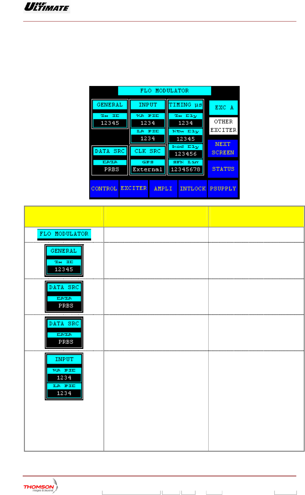
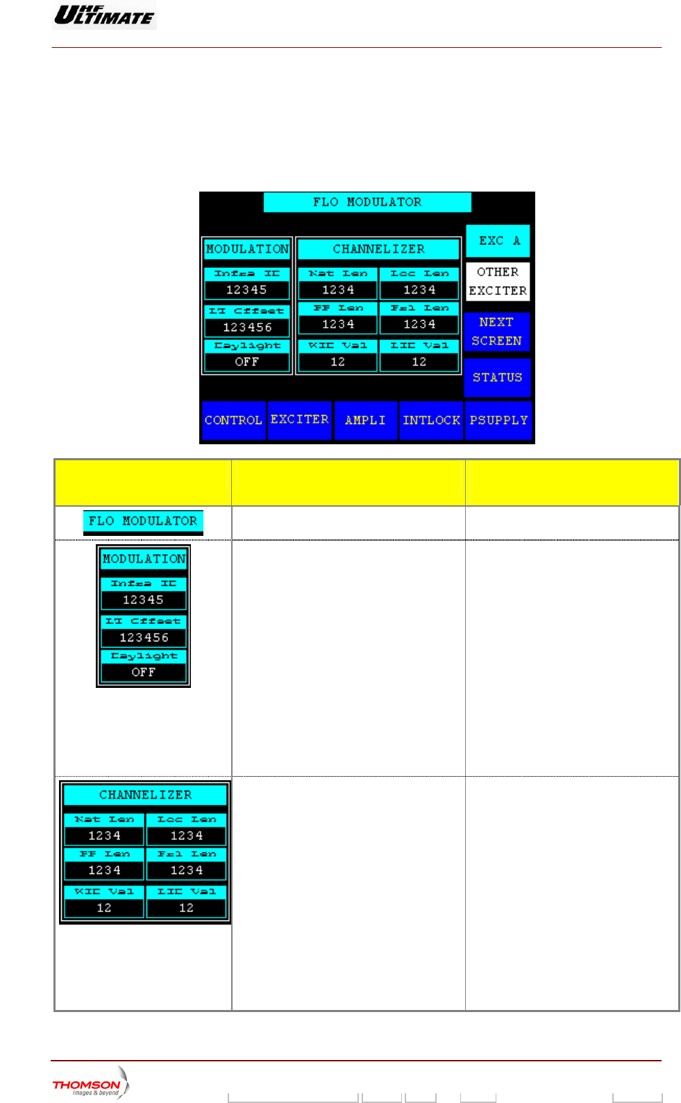
2.1.30. "FLO 1 MODULATOR" window
This window is called up by pressing the "MODUL" control keys in the "EXCITER PANEL" window (SD
transmitters) or in the "EXC w (DD transmitters).
displays the MediaFLO modulator card parameters used in the exciter.
ITER Level 2" windo
It
MESSAGES FUNCTIONS SELECTIONS
AVAILABLE/COMMENTS
Gives the name windows
Displays the transmitter ID number actual in
an SFN network.
This value allows addressing the content
of the MIP to this identified Tx.
Displays the actual input signal type of the
modulator
ASI / PRBS
Displays the actual clock type of the exciter. CLOCK Internal /
GPS Internal / GPS External
Displays the actual process PID number. ♦ WA PID : This value is programmed
Wid Area content process
identification (PID). If the wide area
PID value in the incoming transport
stream matches this value, the
stream is forwarded to the
channelizer as wide area content.
Otherwise, the stream is ignored.
♦ LA PID : This value is programmed
Local Area content process
identification (PID). If the local area
PID value in the incoming transport
stream matches this value, the
stream is forwarded to the
channelizer as local area content.
Otherwise, the stream is ignored.
9932 V2
45321648.01 108 B E Checked 119 / 192
Numéro / Number Doc. Rev. Lan
g
u. 27/06/2006 Pa
g
e
Digital Liquid Cooled UHF
TV Equipment
Use of commands and description of indicators
Information contained is this document is confidential, is THOMSON property and cannot be disclosed in whatever form without prior written authorization of THOMSON.
MESSAGES FUNCTIONS SELECTIONS
AVAILABLE/COMMENTS
Displays the actual delay value. ♦ Mod Dly : The number of clock
cycles corresponding to the delay
through the FLO modulator core.
This is set to align the start of
superframe at the RF output to the
GPS 1PPS.
♦ TX Dly : This value is the latency
the transmit
for the ansmit delay in order to
synchronize transmissions from
multiple sites in an SFN network.
♦ Ntw Dly: This value is the latency
associated with the geographic
separation of transmitters. It’s used
to synchronize transmissions from
multiple sites in an SFN network.
♦ SFN lim: If the absolute value of the
system clock integrity count is
greater than this limit, it is out of
range and an alarm generated.
Pressing this key calls up the
"NUMERICAL VALUE" window in which
this value can be changed.
associated with
hardware. It’s used to compensate
tr
Indicates which isplayed
(
EXC A / EXC B exciter data are d
*)
(*): Only Dual Drive version
CONTROL KEYS FUNCTIONS SELECTIONS
AVAILABLE/COMMENTS
Calls up data from the other exciter (*).
Calls up the "FLO 2 MODULATOR" window.
Calls up the "STATUS" window.
Calls up the "CONTROL LEVEL 1" window.
Calls up the "EXCITER Level 1" window.
Calls up the "AMPLIFIERS" window.
Calls up the «INTERLOCK» window
9932 V2
45321648.01 108 B E Checked 120 / 192
Numéro / Number Doc. Rev. Lan
g
u. 27/06/2006 Pa
g
e
Digital Liquid Cooled UHF
TV Equipment
Use of commands and description of indicators
Information contained is this document is confidential, is THOMSON property and cannot be disclosed in whatever form without prior written authorization of THOMSON.
CONTROL KEYS FUNCTIONS SELECTIONS
AVAILABLE/COMMENTS
Calls up the "POWER SUPPLY" window.
(*): Only Dual Drive version
9932 V2
45321648.01 108 B E Checked 121 / 192
Numéro / Number Doc. Rev. Lan
g
u. 27/06/2006 Pa
g
e
Digital Liquid Cooled UHF
TV Equipment
Use of commands and description of indicators
Information contained is this document is confidential, is THOMSON property and cannot be disclosed in whatever form without prior written authorization of THOMSON.
2.1.31. "FLO 2 MODULATOR" window
This window is called up y pressing the "NEXT SCREEN" control keys in the "MODULATOR FLO 1"
window.
It displays the MediaFLO modulator card parameters used in the
b
exciter.
MESSAGES FUNCTIONS SELECTIONS
AVAILABLE/COMMENTS
Gives the name windows
Displays actual values of the modulati
parameters.
on ♦ Infra ID: This value is inserted into
the infrastructure ID field of the Local
system parameters message. The
network sets this field to the identifier
assigned to the local area
infrastructure.
♦ LT Offset: This value is inserted into
the local time offset field of the local
system parameters message.
♦ Daylight: ON / OFF
This indicator is inserted into the
daylight field of the local system
parameters message.
ON: Local transmitter time is daylight
saving time.
Displays actual values of the channelizer
parameters.
♦ Nat Len: Exciter initialization register
indicates National Length.
♦ Loc Len: Exciter initialization register
indicates Local Length.
♦ PP Len: Exciter initialization register
indicates Positioning Pilot Length.
♦ Fr1 Len: Exciter initialization register
indicates FrameLength.
♦ WID Val: Exciter initialization register
indicates WID scrambler sequence
number.
♦ LID Val: Exciter initialization register
indicates LID scrambler sequence
number
9932 V2
45321648.01 108 B E Checked 122 / 192
Numéro / Number Doc. Rev. Lan
g
u. 27/06/2006 Pa
g
e
Digital Liquid Cooled UHF
TV Equipment
Use of commands and description of indicators
Information contained is this document is confidential, is THOMSON property and cannot be disclosed in whatever form without prior written authorization of THOMSON.
MESSAGES FUNCTIONS SELECTIONS
AVAILABLE/COMMENTS
Indicates which exciter data are displayed
(*)
EXC A / EXC B
(*): Only Dual Drive version
CONTROL KEYS FUNCTIONS SELECTIONS
AVAILABLE/COMMENTS
Calls up data from the other exciter (*).
Calls up the "FLO 1 MODULATOR" window.
Calls up the "STATUS" window.
Calls up the "CONTROL LEVEL 1" window.
Calls up the "EXCITER Level 1" window.
Calls up the "AMPLIFIERS" window.
Calls up the «INTERLOCK» window
Calls up the "POWER SUPPLY" window.
(*): Only Dual Drive version
9932 V2
45321648.01 108 B E Checked 123 / 192
Numéro / Number Doc. Rev. Lan
g
u. 27/06/2006 Pa
g
e

Digital Liquid Cooled UHF
TV Equipment
Use of commands and description of indicators
Information contained is this document is confidential, is THOMSON property and cannot be disclosed in whatever form without prior written authorization of THOMSON.
2.1.32. "COFDM MODULATOR" window
This window is called up by pressing the "MODUL" control keys in the "EXCITER PANEL" window (SD
transmitters) or in the "EXCITER Level 2" window (DD transmitters).
It displays the status of the m Thi window is not available in 8VSB
modulator unit (ATSC Trans
OPTIMUM FA ILY OR ULTIMATE FAMILY
odulator parameters of the exciter. s
mitters).
MAFFINTY FAMILY
CONTROL KEYS FUNCTIONS DISPLAY/COMMENTS
Calls up the " SFN DELAY " window. Control key invisible in MFN mode operation. S
Calls up the "
C
MODULATOR
ONFIGURATION" window.
Calls up the
w
"MODULATOR STATUS"
indow.
Calls up the "MIP DATA" window. Control key invisible in MFN mode operation.
C
w
alls up the "TRANSMITTER STATUS"
indow.
Calls up the "CONTROL Level 1" window.
Calls up the "EXCITER Level 2" w (for
a Double Drive transmitter) or the "EXCITER
PANEL" window (for a Single Drive
transmitter).
windo
C
alls up the "AMPLIFIERS" window. (a)
9932 V2
45321648.01 108 B E Checked 124 / 192
Numéro / Number Doc. Rev. Lan
g
u. 27/06/2006 Pa
g
e
Digital Liquid Cooled UHF
TV Equipment
Use of commands and description of indicators
Information contained is this document is confidential, is THOMSON property and cannot be disclosed in whatever form without prior written authorization of THOMSON.
CONTROL KEYS FUNCTIONS DISPLAY/COMMENTS
Calls up the " SFN DELAYS" window. Control key invisible in MFN mode operation.
Calls up the "MODULATOR
CONFIGURATION" window.
Calls up the "MODULATOR STATUS"
window.
C n n MFN mode operation.alls up the "MIP DATA" window. Co trol key invisible i
Calls up the «INTERLOCK» window (a)
Calls u
p the "POWER SUPPLY" window. (a)
Calls up the "AFFINITY" window. (b)
(a): Not Visible for AFFINITY family
(b): Not Visible for OPTIMUM or ULTIMATE families
MESSAGE FUNCTIONS DISPLAY/COMMENTS
Gives the window name.
9932 V2
45321648.01 108 B E Checked 125 / 192
Numéro / Number Doc. Rev. Lan
g
u. 27/06/2006 Pa
g
e
Digital Liquid Cooled UHF
TV Equipment
Use of commands and description of indicators
Information contained is this document is confidential, is THOMSON property and cannot be disclosed in whatever form without prior written authorization of THOMSON.
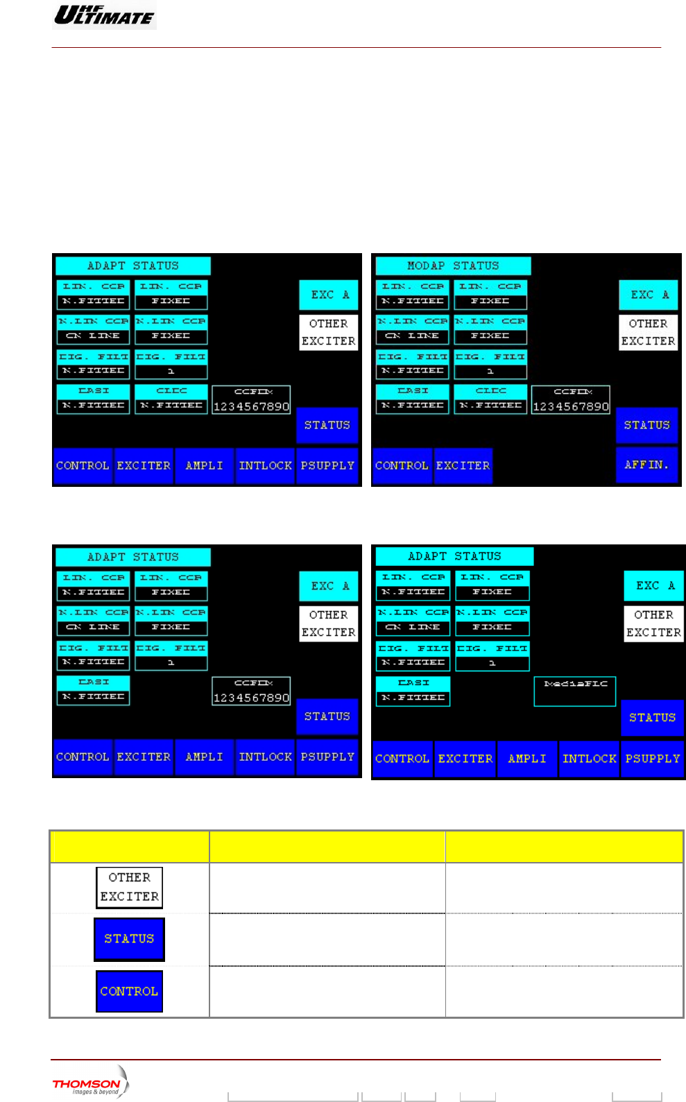
2.1.33. "ADAPT PARAMETERS" window
This window is called up by pressing the "ADAPT" control keys in the "EXCITER PANEL" window (SD
transmitters) or in the "EXCITER Level 2" window (DD transmitters).
It displays or B. the status of the ADAPTive parameters of exciter A
MODAP VERSION
OPTIMUM FAMILY OR ULTIMATE FAMILY AFFINTY FAMILY
SIRIUS VERSION
OPTIMUM F IMATE FAMILY
AMILY OR ULT
OTHER MOD MEDIAFLO MODULATOR
ULATOR
CONTROL KEYS FUNCTIONS DISPLAY/COMMENTS
Calls up data from the other exciter. (*)
Calls up the "TRANSMITTER STATUS"
window.
Calls up the "CONTROL Level 1" window.
9932 V2
45321648.01 108 B E Checked 126 / 192
Numéro / Number Doc. Rev. Lan
g
u. 27/06/2006 Pa
g
e
Digital Liquid Cooled UHF
TV Equipment
Use of commands and description of indicators
Information contained is this document is confidential, is THOMSON property and cannot be disclosed in whatever form without prior written authorization of THOMSON.
CONTROL KEYS FUNCTIONS DISPLAY/COMMENTS
Calls up the "EXCITER Level 1" window or
ndow.
the "EXCITER PANEL" wi
Calls up the "AMPLIFIERS" window. (a)
Calls up the «INTERLOCK» window (a)
Calls up the "POWER SUPPLY" window. (a)
Calls up the "AFFINITY" window. (b)
(*) Only in Double Drive Version.
(a): Not Visible for AFFINITY family
(b): Not Visible for OPTIMUM or ULTIMATE families
MESSAGES FUNCTIONS DISPLAY/COMMENTS
Gives the window name.
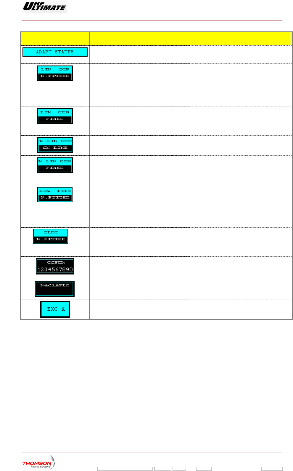
Indicates the status of the linearity correction
(Adaptive Linear Equaliser).
♦ MODAP version
LIN. COR N. FITTED/ LIN. COR ON LINE /
LIN. COR BYPASSED
♦ SIRIUS version
LIN. COR ON LINE / LIN. COR BYPASSED
Displays the type of linearity correction
performed by the ALE card of the EXCITER
(fixed or adaptive).
LIN. COR FIXED /
LIN. COR ADAPTATIVE
In fixed position, the correction parameters
are not continuously adjusted.
Indicates the status, ON LINE or
BYPASSED, of the non linearity correction
(Look Up Table).
N. LIN COR ON LINE /
N. LIN COR BYPASSED
Displays the type of non linearity correction
performed by the LUT module of the
EXCITER (fixed or adaptive).
N. LIN. COR FIXED /
N. LIN. COR ADAPTATIVE
In fixed position, the correction parameters
are not continuously adjusted.
Indicates the status of the digital filter
correction.
♦ MODAP version
DIG. FILT NOT FITTED / DIG. FILT ON LINE
/ DIG. FILT BYPASSED
♦ SIRIUS version
DIG. FILT ON LINE / DIG. FILT BYPASSED
Displays the reference table of the digital
filter (1 to 5).
Displays whether a Double ASI input is
present or absent in the EXCITER unit.
DASI FITTED / DASI N. FITTED
9932 V2
45321648.01 108 B E Checked 127 / 192
Numéro / Number Doc. Rev. Lan
g
u. 27/06/2006 Pa
g
e
Digital Liquid Cooled UHF
TV Equipment
Use of commands and description of indicators
Information contained is this document is confidential, is THOMSON property and cannot be disclosed in whatever form without prior written authorization of THOMSON.
MESSAGES FUNCTIONS DISPLAY/COMMENTS
Gives the window name.
(Adaptive Linear Equaliser).
Indicates the status of the linearity correction ♦ MODAP version
LIN. COR N. FITTED/ LIN. COR ON LINE /
LIN. COR BYPASSED
♦ SIRIUS version
LIN. COR ON LINE / LIN. COR BYPASSED
s the type of linearity correction
ed by the ALE card of the EXCITER
(fixed or adaptive).
LIN. COR FIXED /
LIN. COR ADAPTATIVE
In fixed position, the correction parameters
are not continuously adjusted.
Display
perform
Indicates the status, ON LINE or
BYPASSED, of the non linearity correction
(Look Up Table).
N. LIN COR ON LINE /
N. LIN COR BYPASSED
Displays the type of non linearity correction
performed by the LUT module of the
EXCITER (fixed or adaptive).
N. LIN. COR FIXED /
N. LIN. COR ADAPTATIVE
In fixed position, the correction parameters
are not continuously adjusted.
Indicates the status of the digital filter
correction.
♦ MODAP version
DIG. FILT NOT FITTED / DIG. FILT ON LINE
/ DIG. FILT BYPASSED
♦ SIRIUS version
DIG. FILT ON LINE / DIG. FILT BYPASSED
(1)
Displays whether an OLDC unit is present or
absent in the MODAP unit. DC ” key in “ADAPT STATUS”
indow is not available (not visible) when the
XCITER type is SIRIUS.
OLDC FITTED / OLDC N. FITTED
Note: The “ OL
w
E
Displays which type of modulator processes
the input signal.
IFIQ BOARD /
COFDM EXT 8MHz / COFDM EXT 7MHz /
COFDM BOARD 8MHz /
COFDM BOARD 7MHz /
COFDM BOARD 6MHz /
8VSB BOARD /
MediaFLO
Indicates which exciter data are displayed.(*) XC A / EXC B E
(*)
(1)
Only in Double Drive Version.
Only in ODAP vers
M ion with OLDC
9932 V2
45321648.01 108 B E Checked 128 / 192
Numéro / Number Doc. Rev. Lan
g
u. 27/06/2006 Pa
g
e
Digital Liquid Cooled UHF
TV Equipment
Use of commands and description of indicators
Information contained is this document is confidential, is THOMSON property and cannot be disclosed in whatever form without prior written authorization of THOMSON.
2.1.34. "DASI STATUS" window
This window is called up by pressing the "DASI" control keys in the "EXCITER PANEL" window (SD
transmitters) or in the "EXCITER Level 2" window (DD transmitters).
It displays th f Excite A or B.
MODAP VERSION
OPTIMUM FAMILY OR ULTIMATE FAMILY
e status of the double ASI input parameters o r
AFFINTY FAMILY
SIRIUS VERSION
CONTROL KEYS FUNCTIONS DISPLAY/COMMENTS
Calls up the "CONTROL Level 1" window.
Calls up the "EXCITER Level 2" window (for a
Double Drive transmitter) or the "EXCITER
PANEL" window (for a Single Drive
transmitter).
Calls up the "AMPLIFIERS" window.
9932 V2
45321648.01 108 B E Checked 129 / 192
Numéro / Number Doc. Rev. Lan
g
u. 27/06/2006 Pa
g
e
Digital Liquid Cooled UHF
TV Equipment
Use of commands and description of indicators
Information contained is this document is confidential, is THOMSON property and cannot be disclosed in whatever form without prior written authorization of THOMSON.
CONTROL KEYS FUNCTIONS DISPLAY/COMMENTS
Calls up the "AMPLIFIERS" window. (a)
Calls up the «INTERLOCK» window (a)
Calls up the "POWER SUPPLY" window. (a)
lls up the "AFFINITY" window. (b) Ca
Calls up data from the other exciter. (*)
Selects the Transport Stream to be connect
to the SIRIUS Exciter . (1
ed
)
Cancels a selection. (1)
Validates a selection. (1)
(*) : Only Dual-Drive versio
(1) : Only SIRIUS version.
(a): Not Visible for AFFINITY family
(b): Not Visible for OPTIMUM or ULTIMATE families
n.
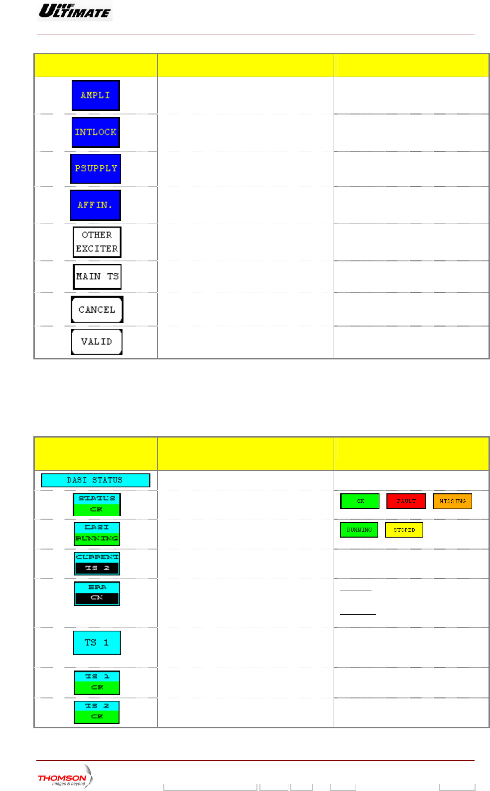
INDICATOR LAMPS AND
MESSAGE DISPLAYS
FUNCTIONS DISPLAY/COMMENTS
Gives the window name.
Indicates the status of the Dual ASI input.
/ /
Indicates the overall status of the Dual ASI
input.
/
Indicates which ASI i
nput is operating. TS 1 / TS 2
Indicates if DASI function is operating. (**) BRA ON: the BRA function is operating,
the actual mode of the network is MFN
SFN OFF: If the transmitter is on SFN
mode, the BRA function is ineffective
Indicates the Transport Stream selected. TS 1
Flashes until the "MAIN TS" command is
either validated or cleared.
/ TS 2
Indicates presence or absence of an MPEG1
input signal on the exciter. (1)
TS 1 OK / TS 1 MISSING
Indicates presence or absence of an MPEG2
input signal on the exciter. (1)
TS 2 OK / TS 2 MISSING
9932 V2
45321648.01 108 B E Checked 130 / 192
Numéro / Number Doc. Rev. Lan
g
u. 27/06/2006 Pa
g
e
Digital Liquid Cooled UHF
TV Equipment
Use of commands and description of indicators
Information contained is this document is confidential, is THOMSON property and cannot be disclosed in whatever form without prior written authorization of THOMSON.
INDICATOR LAMPS AND
MESSAGE DISPLAYS
FUNCTIONS DISPLAY/COMMENTS
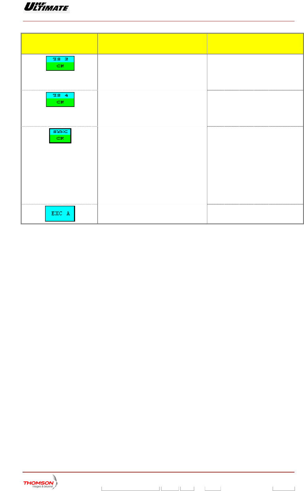
Indicates presence or absence of an MPEG3
input signal on the exciter. (1) (2)
TS 3 OK / TS 3 MISSING
This key in “DASI STATUS” window is
not available (not visible) when the
optional card (Extension Input) is not
present.
In
dicates presence or absence of an MPEG4
input signal on the exciter. (1) (2)
TS 4 OK / TS 4 MISSING
This key in “DASI STATUS” window is
not available (not visible) when the
optional card (Extension Input) is not
present.
Indicates presence or absence of an
synchronization of MPEG input signal on the
exciter. (1) (3)
SYNC OK / SYNC MISSING
SYNC OK:
The MPEG is synchronized or there is a
loss of one frame.
SYNC MISSING
If a loss of frame condition persists for 2
consecutive frames, the synchronization
status is declared MISSING.
If 7 occurrences of the transport stream
framing byte is detected in the proper
place the status is declared OK
Indicates which exciter data are displayed. (*) EXC A / EXC B
(*) : Dual-Drive version Only.
(**) : MODAP version Only.
(1) : SIRIUS version Only.
(2) : Unavailable with MediaF
(3) : MediaFLO modulator only.
LO modulator.
9932 V2
45321648.01 108 B E Checked 131 / 192
Numéro / Number Doc. Rev. Lan
g
u. 27/06/2006 Pa
g
e
Digital Liquid Cooled UHF
TV Equipment
Use of commands and description of indicators
Information contained is this document is confidential, is THOMSON property and cannot be disclosed in whatever form without prior written authorization of THOMSON.
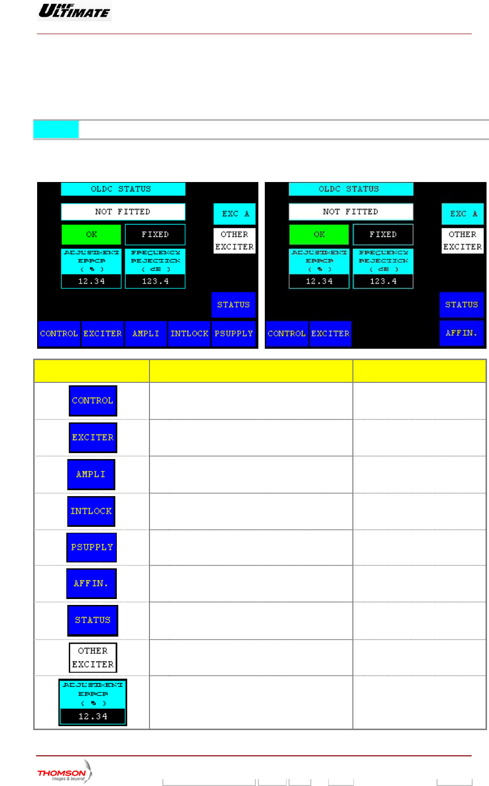
2. US" window, MODAP version ONLY
This window is called up by R PANEL" window (SD
transmitters) or in the "EXCITER Level 2" window (DD transmitters).
1.35. "OLDC STAT
pressing the "OLDC" control keys in the "EXCITE
NOTE : This window is available in MODAP version only
It displays the status of the OLDC parameters of Exciter A or B.
OPTIMUM FAMILY OR ULTIMATE FAMILY AFFINTY FAMILY
CONTROL KEYS FUNCTIONS DISPLAY/COMMENTS
Calls up the "CONTROL Level 1" window.
Calls up the "EXCITER Level 2" window (for a Double
Drive transmitter) or the "EXCITER PANEL" window
(for a Single Drive transmitter).
Calls up the "AMPLIFIERS" window. (a)
Calls up the «INTERLOCK» window (a)
Calls up the "POWER SUPPLY" window. (a)
Calls up the "AFFINITY" window. (b)
Calls up the "TRANSMITTER STATUS" window.
Calls up data from the other exciter. (*)
Displays the measured I/Q amplitude error value. Available in Adaptive mode only.
9932 V2
45321648.01 108 B E Checked 132 / 192
Numéro / Number Doc. Rev. Lan
g
u. 27/06/2006 Pa
g
e
Digital Liquid Cooled UHF
TV Equipment
Use of commands and description of indicators
Information contained is this document is confidential, is THOMSON property and cannot be disclosed in whatever form without prior written authorization of THOMSON.
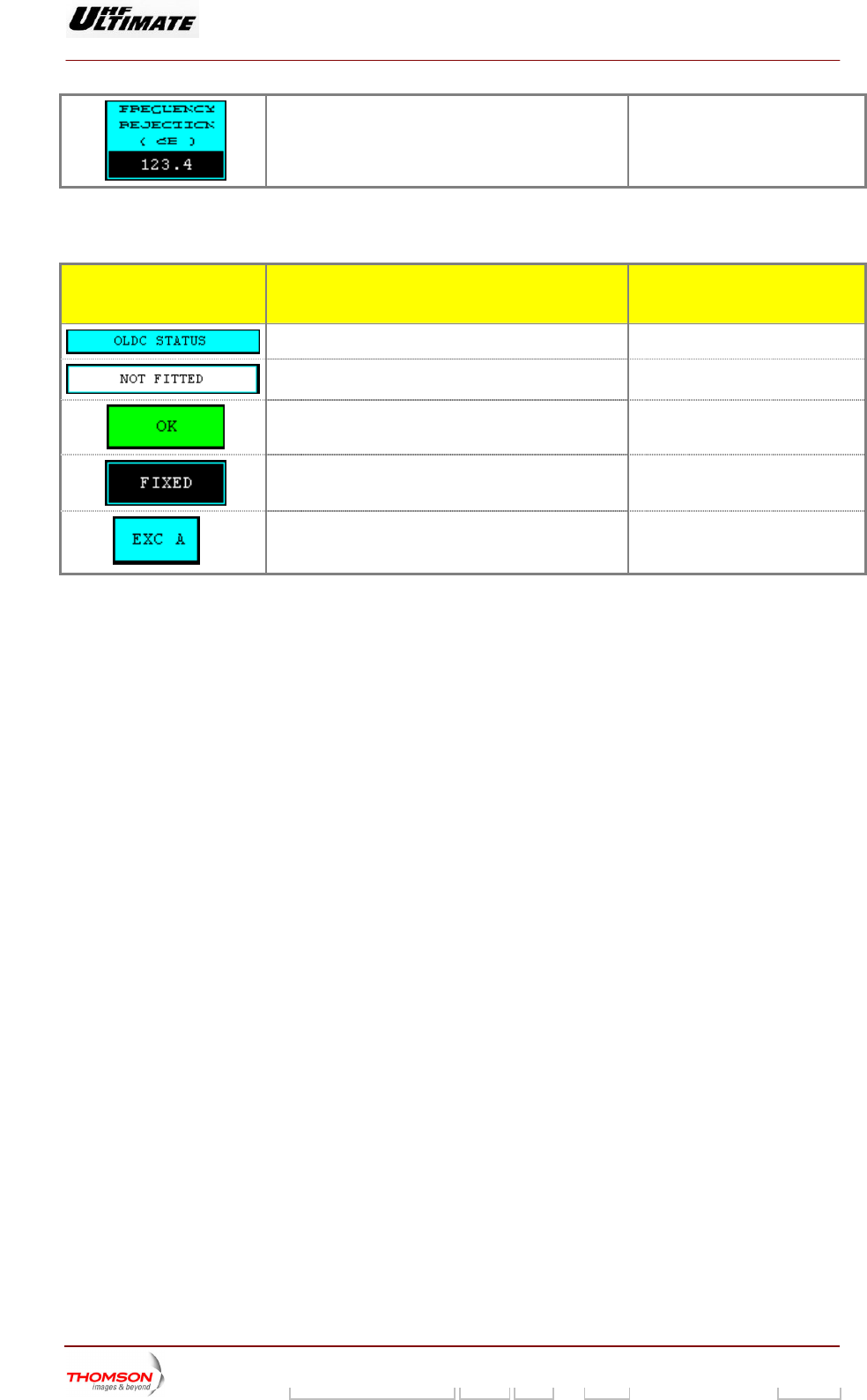
Displays the measured central frequency rejection Available in Adaptive mode only.
value.
(a): Not Visible for AFFINITY family
(b): Not Visible for OPTIMUM or ULTIMATE families
INDICATOR LAMPS AND
MESSAGE DISPLAYS
FUNCTIONS DISPLAY/COMMENTS
Gives the window name.
Displays whether an OLDC card is present or absent. FITTED / NOT FITTED
Indicates the status of the OLDC card. OK / FAULT / MISSING
Displays the current operating mode of the OLDC card. ADAPTATIVE / FIXED
(*)
Indicates which exciter data are displayed. EXC A / EXC B
(*) : Only Dual-Drive version.
9932 V2
45321648.01 108 B E Checked 133 / 192
Numéro / Number Doc. Rev. Lan
g
u. 27/06/2006 Pa
g
e
Digital Liquid Cooled UHF
TV Equipment
Use of commands and description of indicators
Information contained is this document is confidential, is THOMSON property and cannot be disclosed in whatever form without prior written authorization of THOMSON.
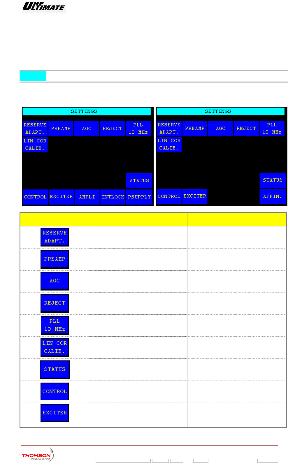
2.1.36. "SETTINGS" window, SIRIUS version ONLY
This window is called up by pressing the "SETTING" control keys in the "EXCITER PANEL" window
(SD transmitters) or in the "EXCITER Level 2" window (DD transmitters).
NOTE: This window is available in SIRIUS version only.
This window i available in M ly.
OPTIMUM FAMILY OR U
s aintenance mode on
LTIMATE FAMILY AFFINTY FAMILY
CONTROL KEYS FUNCTIONS DISPLAY/COMMENTS
C RVE ADAPTATIVITY
S
Control key invisible in Dual Drive alls up the " RESE
ETTING" window. configuration.
Calls up the "PREAMPLI SETTING" window.
Calls up the "AGC SETTING" window.
C
w
alls up the "LOCAL / IMAGE REJECT"
indow.
Calls up the "ADJUSTMENT 10Mhz"
window.
Calls up the "LINear CORrection
CALIBration" window.
windo
Calls up the "TRANSMITTER STATUS"
w.
Calls up the "CONTROL Level 1" window.
Calls up the "EXCITER Level 2" window (for
a Double Drive transmitter) or the "EXCITER
PANEL" window (for a Single Drive
transmitter).
9932 V2
45321648.01 108 B E Checked 134 / 192
Numéro / Number Doc. Rev. Lan
g
u. 27/06/2006 Pa
g
e
Digital Liquid Cooled UHF
TV Equipment
Use of commands and description of indicators
Information contained is this document is confidential, is THOMSON property and cannot be disclosed in whatever form without prior written authorization of THOMSON.
CONTROL KEYS FUNCTIONS DISPLAY/COMMENTS
Calls up the "AMPLIFIERS" window. (a)
Calls up the «INTERLOCK» window (a)
Calls up the "POWER SUPPLY window. (a) "
Calls up the "A . (b) FFINITY" window
(a): Not Visible for AFFINITY family
(b): Not Visible for OPTIMUM
or ULTIMATE families
MESSAGE FUNCTIONS DISPLAY/COMMENTS
G ives the window name.
9932 V2
45321648.01 108 B E Checked 135 / 192
Numéro / Number Doc. Rev. Lan
g
u. 27/06/2006 Pa
g
e
Digital Liquid Cooled UHF
TV Equipment
Use of commands and description of indicators
Information contained is this document is confidential, is THOMSON property and cannot be disclosed in whatever form without prior written authorization of THOMSON.
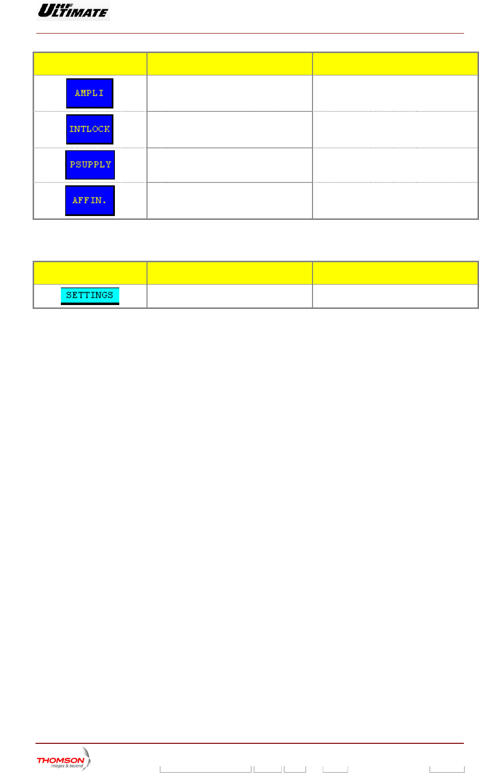
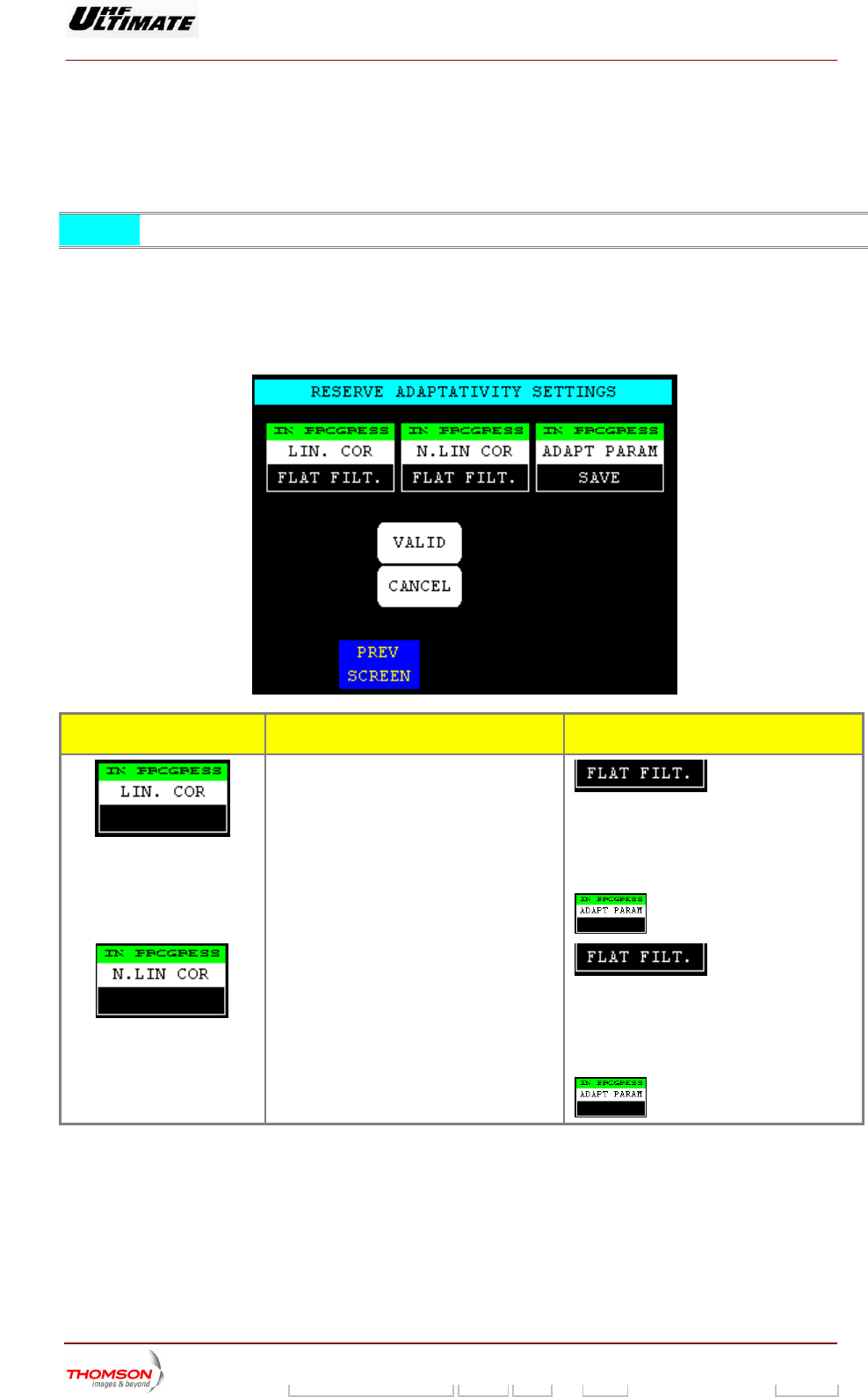
2. DAPTATIVITY SETTINGS" window, SIRIUS version ONLY
This window is called up APT RESERVE ontrol keys in the "SETTINGS"
window.
1.37. "RESERVE A
by pressing the "AD " c
NOTE : This wi ow is available in SIRIUS version only nd
This window is only available in Maintenance mode and in Dual Drive configuration transmitter
The window allows to configure the state of the not linear corrections and to display that current for the
reserve exciter.
OPTIMUM FAMILY OR ULTIMATE FAMILY
CONTROL KEYS FUNCTIONS DISPLAY/COMMENTS
Controls the loading of the linear correction
with flat filter coefficients.
Press this key and validation allows verifying
the good operating WITHOUT correction.
Note: To feedback to old coefficients used
the function RECALL of the control key
“ADAPT PARAM”
Controls the loading of the no linear
correction with flat filter coefficients.
Press this key and validation allows verifying
the good operating WITHOUT correction.
Note: To feedback to old coefficients used
the function RECALL of the control key
“ADAPT PARAM”
9932 V2
45321648.01 108 B E Checked 136 / 192
Numéro / Number Doc. Rev. Lan
g
u. 27/06/2006 Pa
g
e
Digital Liquid Cooled UHF
TV Equipment
Use of commands and description of indicators
Information contained is this document is confidential, is THOMSON property and cannot be disclosed in whatever form without prior written authorization of THOMSON.
CONTROL KEYS FUNCTIONS DISPLAY/COMMENTS
Selects the coefficients of the corrections for Press this contr
reserve exciter ♦ SAVE : Allows saving coefficients into
ol key and validation:
tables of corrections.
♦ RECALL: Allows verifying the good
operating WITH corrections by using
coefficients beforehand recorded during
the equipment line-up procedure:
Recalls the coefficients of the last save.
Validates a sele ction.
Cancels a selection.
C alls up the "SETTINGS" window.
INDICATOR L PS AND FUNCTIONS DISPLAY/COMMENTS AM
MESSAGE DISPLAYS
Give the window name.
9932 V2
45321648.01 108 B E Checked 137 / 192
Numéro / Number Doc. Rev. Lan
g
u. 27/06/2006 Pa
g
e
Digital Liquid Cooled UHF
TV Equipment
Use of commands and description of indicators
Information contained is this document is confidential, is THOMSON property and cannot be disclosed in whatever form without prior written authorization of THOMSON.
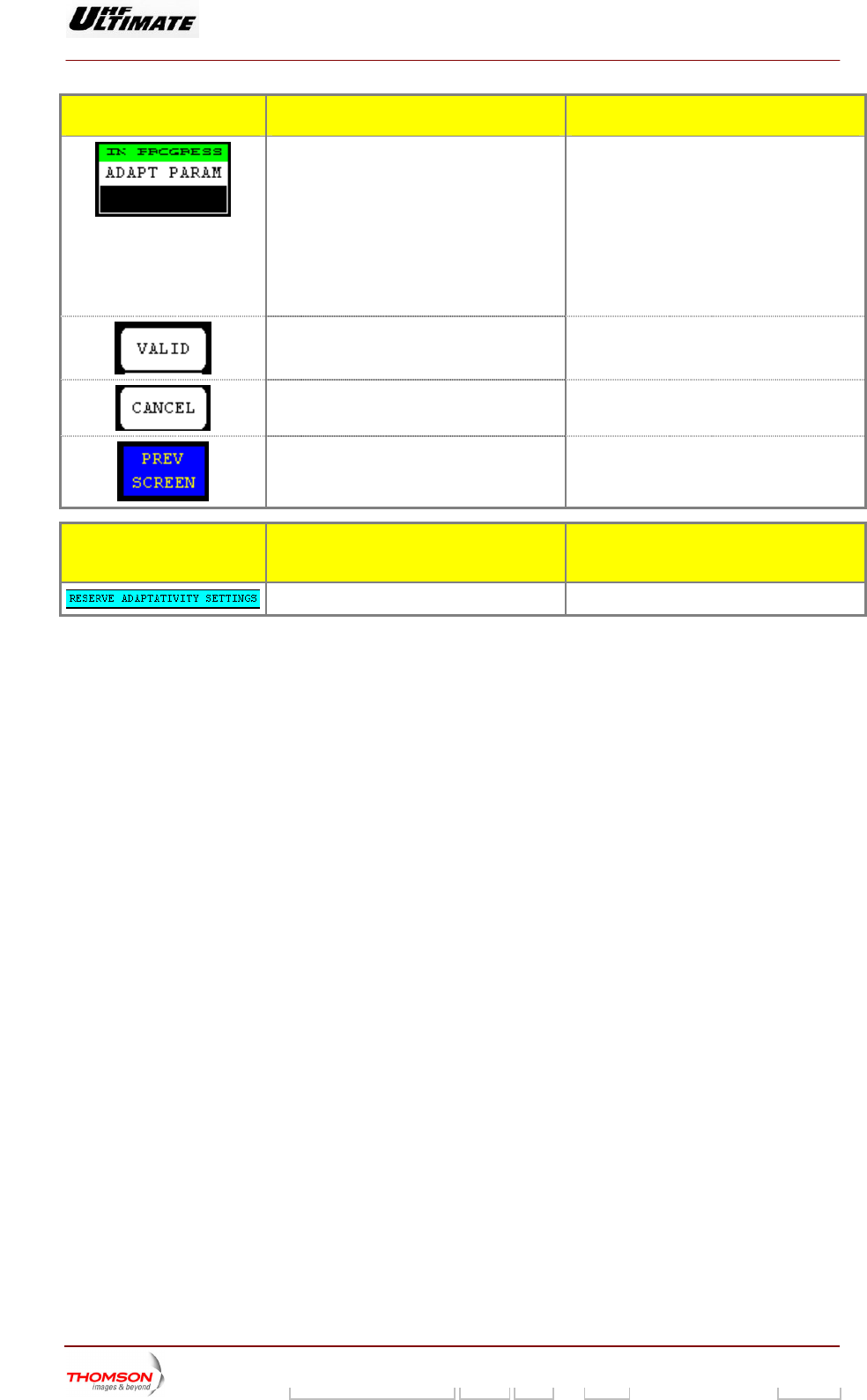
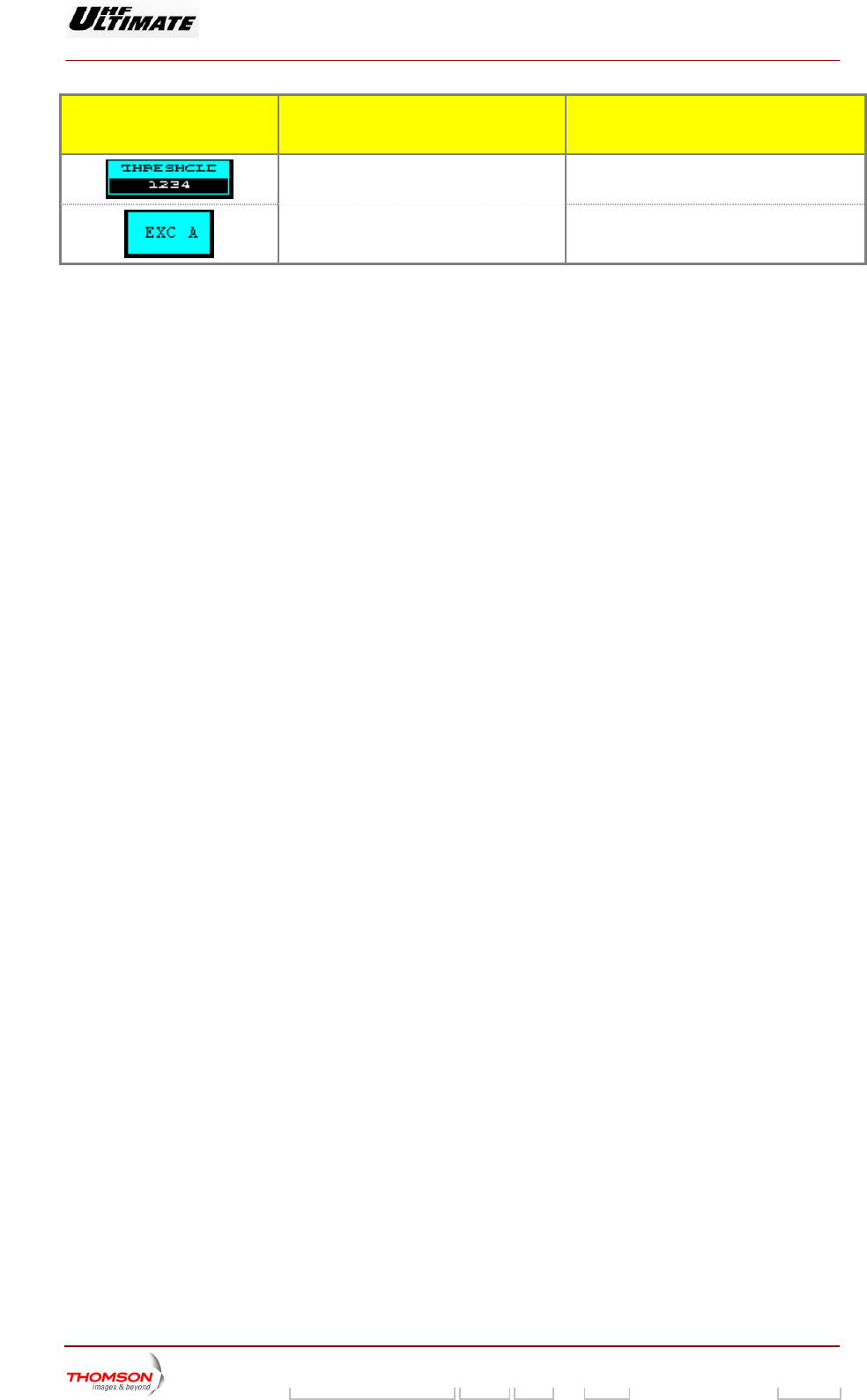
2.1.38. "PREAMPLI SETTING" window, SIRIUS version ONLY
This window is called up by pressing the "PREAMP" control keys in the "SETTINGS" window.
NOTE : This window is available in SIRIUS version only
This window is only available in Maintenance mode. It displays the status of RF preamplifier
parameters of exciter A or B.
Figure 30 : Exciter on Antenna ( D.D.) Figure 31 : Exciter on Dummy load ( D.D.)
CONTROL KEYS FUNCTIONS DISPLAY/COMMENTS
Validates a selection.
Cancels a selection.
Set the reference value of the threshold in
the RF preamplifier.
Only available for the exciter on antenna
Flashes until the “SET REFER”” command is
either validated or cleared.
Appelle les données de l’autre EMB (*).
Calls up the "SETTINGS" window.
INDICATOR LAMPS AND
MESSAGE DISPLAYS
FUNCTIONS DISPLAY/COMMENTS
Give the window name.
Displays the transmitted RF power value. This value is expressed in a percentage of
calibrated power value.
Displays the current value of the output
preamplifier that is applied to the RF chain
of the transmitter.
9932 V2
45321648.01 108 B E Checked 138 / 192
Numéro / Number Doc. Rev. Lan
g
u. 27/06/2006 Pa
g
e
Digital Liquid Cooled UHF
TV Equipment
Use of commands and description of indicators
Information contained is this document is confidential, is THOMSON property and cannot be disclosed in whatever form without prior written authorization of THOMSON.
INDICATOR LAMPS AND
MESSAGE DISPLAYS
FUNCTIONS DISPLAY/COMMENTS
Displays the fault threshold value of the RF
preamplifier.
Indicates which exciter data are displayed EXC A / EXC B
(*).
(*): Only Dual Drive version.
9932 V2
45321648.01 108 B E Checked 139 / 192
Numéro / Number Doc. Rev. Lan
g
u. 27/06/2006 Pa
g
e
Digital Liquid Cooled UHF
TV Equipment
Use of commands and description of indicators
Information contained is this document is confidential, is THOMSON property and cannot be disclosed in whatever form without prior written authorization of THOMSON.
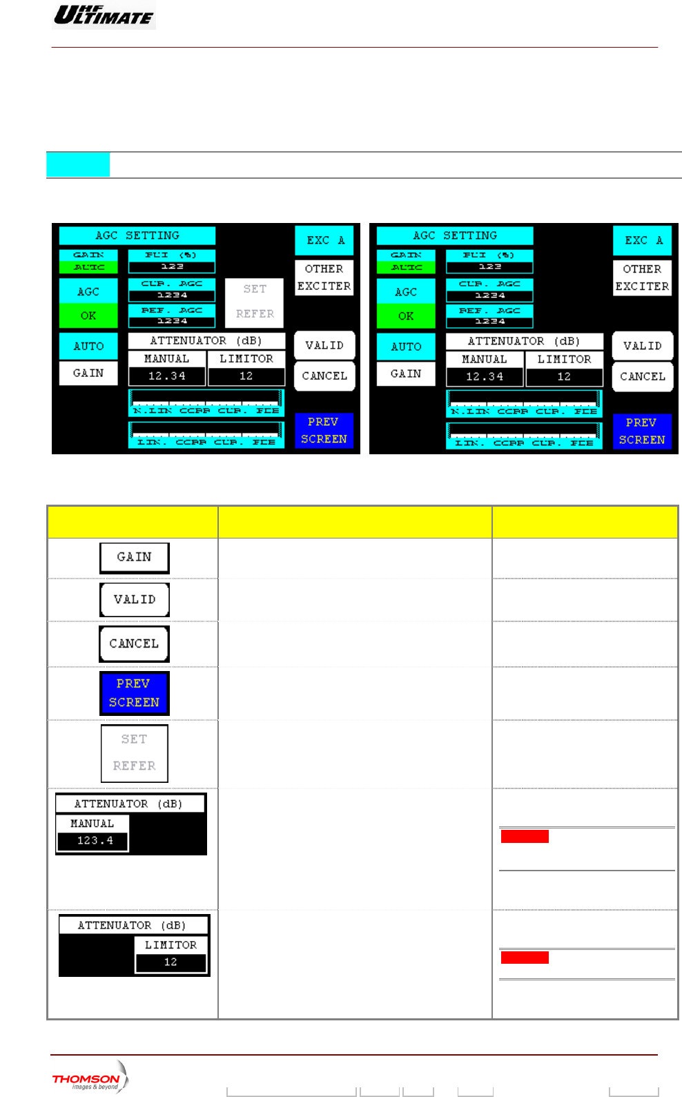
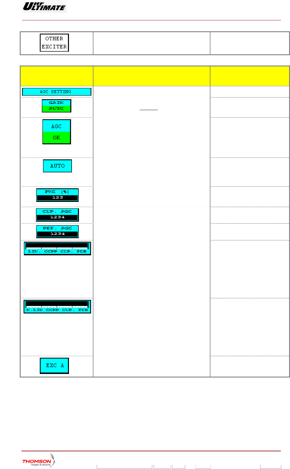
2.1.39. "AGC SETTING" window, SIRIUS version ONLY
This window is called up by pressing the "AGC" control keys in the "SETTINGS".
NOTE : This window is available in SIRIUS version only.
This windows is available in Maintenance mode only. It displays the status of the AGC parameters of
Exciter A or B.
Figure 32 : Exciter on air mitter D.D. for Trans Figure 33 : E itter D.D.
xciter on load for Transm
CONTROL KEYS FUNCTIONS DISPLAY/COMMENTS
Selects the GAIN control mode (manual or
automatic) for AGC of the transmitter PCL is locked (disabled).
Command is disabled while the
Validates a selection.
Cancels a selection.
Calls up the "SETTING" window.
Set the reference value in Auto Gain Control
loop. REFER””
d is either validated or
cleared.
(AGC) Available with on-air exciter only.
Flashes until the “SET
comman
Calls up the “NUMERICAL VALUE” window in which
ontrol value (MGC) can be changed
Displays the attenuation value
Command is disabled while the
PCL is locked (disabled).
the Main Gain C
Warning: This attenuator adjusts
the output power in manual gain of
the transmitter.
It’s to be expressed in dB. The
maximum attenuation is 25.0
Calls up the “NUMERICAL VALUE” window in which
the LIMITOR value can be changed
Displays the attenuation value
Command is disabled while the
PCL is locked (disabled).
Warning: This attenuator limits the
RF output of SIRIUS Exciter.
It’s to be expressed in dB. The
maximum attenuation is 25
9932 V2
45321648.01 108 B E Checked 140 / 192
Numéro / Number Doc. Rev. Lan
g
u. 27/06/2006 Pa
g
e
Digital Liquid Cooled UHF
TV Equipment
Use of commands and description of indicators
Information contained is this document is confidential, is THOMSON property and cannot be disclosed in whatever form without prior written authorization of THOMSON.
(*)
Calls up data from the other exciter.
INDICATOR LAMPS AND
MESSAGE DISPLAYS
FUNCTIONS DISPLAY/COMMENTS
Gives the window name.
Displays, which gain control mode (MANUAL or
AUTOMATIC) is currently picked up by the
transmitter
GAIN MANUAL / GAIN AUTO
Indicates the status of the AGC loop.
AGC OK / AGC FAULT
FAULT: The AGC voltage is out of
the operation range:+-2dB (0,5V to
2,5V) regarding AGC reference.
It’s displays in “AGC SETTING”
screen.
Displays which gain control mode is selected AUTO / MANUAL
GAIN””
ted or
cleared.
Flashes until the “
command is either valida
Displays the transmitted RF power value This value is expressed in a
percentage of the calibrated power
value.
Displays the current value for the Auto Gain C
(AGC) loop that is picked up by the transmitter.
ontrol
Displays the reference value in Auto Gain C
(AGC) that is used.
ontrol
Indicates the level of the feedback signal for Linear
Correction (Ripple)
Green indication: OK
used:
to +2dBm
Red indication: FAULT
The RF feedback level is out of the
range:
FLO or COFDM modulator used:
typical –10dBm to 0dBm
8VSB modulator
typical –15dBm
Indicates the level of the feedback signal for Linear Green indication: OK
modulator used:
typical –10dBm to 0dBm
8VSB modulator used:
Correction (Shoulder) Red indication: FAULT
The RF feedback level is out of the
range:
FLO or COFDM
typical –15dBm to +2dBm
(*)
C A / EXC B Indicates which exciter data are displayed. EX
(*) : Only Dual-Drive v rsion.
e
9932 V2
45321648.01 108 B E Checked 141 / 192
Numéro / Number Doc. Rev. Lan
g
u. 27/06/2006 Pa
g
e
Digital Liquid Cooled UHF
TV Equipment
Use of commands and description of indicators
Information contained is this document is confidential, is THOMSON property and cannot be disclosed in whatever form without prior written authorization of THOMSON.
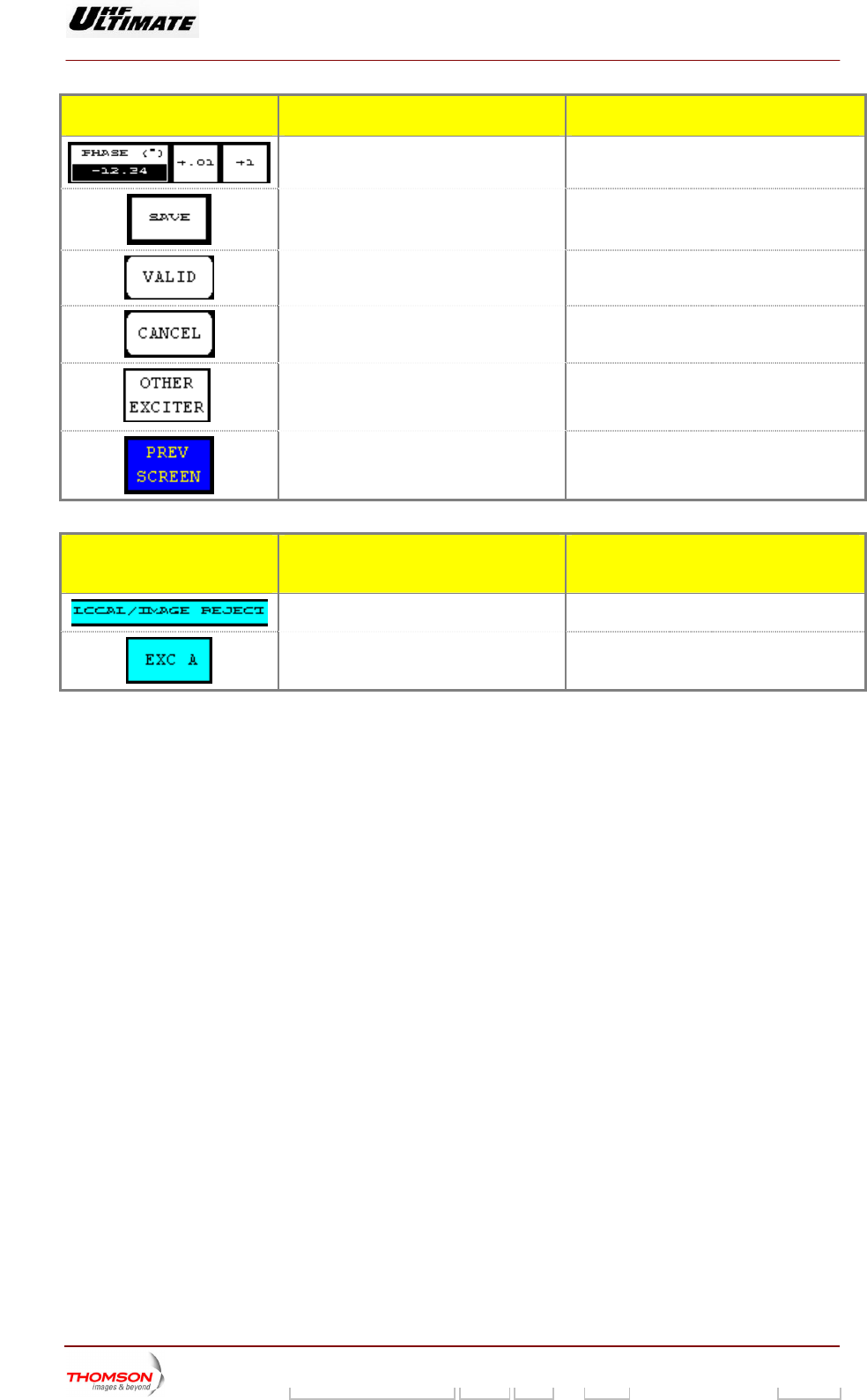
2.1.40. "LOCAL/IMAGE REJECT" window, SIRIUS version ONLY
This window i ed up by p keys in the "SETTINGS" window. s call ressing the "REJECT" control
NOTE : This window is available in SIRIUS version only.
This window is only available in maintenance mode.
CONTROL KEYS FUNCTIONS DISPLAY/COMMENTS
Decrements the adjustment value of the
“OFFSET I” by step of 1 or by step of 10.
Displays the adjustment value of the
“OFFSET I”
Increments the adjustment value of the
“OFFSET I” by step of 1 or by step of 10.
Decrements the adjustment value of the
“OFFSET Q” by step of 1 or by step of 10.
Displays the adjustment value of the
“OFFSET Q”
Increments the adjustment value of the
“OFFSET Q” by step of 1 or by step of 10.
Allows to adjust the I & Q/RF modulator
(Local Oscilator Rejection)
Obtain the maximum rejection of the local
frequency (<35dB).
The adjustments are directly applied to the
basic transmitter.
Decrements the adjustment value of the
GAIN by step of 1 or by step of 10.
Displays the adjustment value of the GAIN.
Increments the adjustment value of the
GAIN by step of 1 or by step of 10.
Decrements the adjustment value of the
PHASE by step of 1 or by step of 10.
Displays the adjustment value of the
PHASE.
Allows to adjust the rejection of the
unwanted lateral band (image Rejection)
The adjustments are directly applied to the
basic transmitter.
9932 V2
45321648.01 108 B E Checked 142 / 192
Numéro / Number Doc. Rev. Lan
g
u. 27/06/2006 Pa
g
e
Digital Liquid Cooled UHF
TV Equipment
Use of commands and description of indicators
Information contained is this document is confidential, is THOMSON property and cannot be disclosed in whatever form without prior written authorization of THOMSON.
CONTROL KEYS FUNCTIONS DISPLAY/COMMENTS
PHASE by step of 1 or by step of 10.
Increments the adjustment value of the
Allows saving adjustments above in the
basic transmitter.
Flashes until the “SAVE” command is either
validated or cleared.
Validates a selection.
Cancels a selection.
Calls up data from the other exciter. (*)
Calls up the "SETTINGS" window.
INDICATOR LAMPS AND
MESSAGE DISPLAYS
FUNCTIONS DISPL Y/COMMENTS A
Gives the window name.
Indicates which exciter data are displayed.
(*).
EXC A / EXC B
(*) : Only Dual-Drive version.
9932 V2
45321648.01 108 B E Checked 143 / 192
Numéro / Number Doc. Rev. Lan
g
u. 27/06/2006 Pa
g
e
Digital Liquid Cooled UHF
TV Equipment
Use of commands and description of indicators
Information contained is this document is confidential, is THOMSON property and cannot be disclosed in whatever form without prior written authorization of THOMSON.
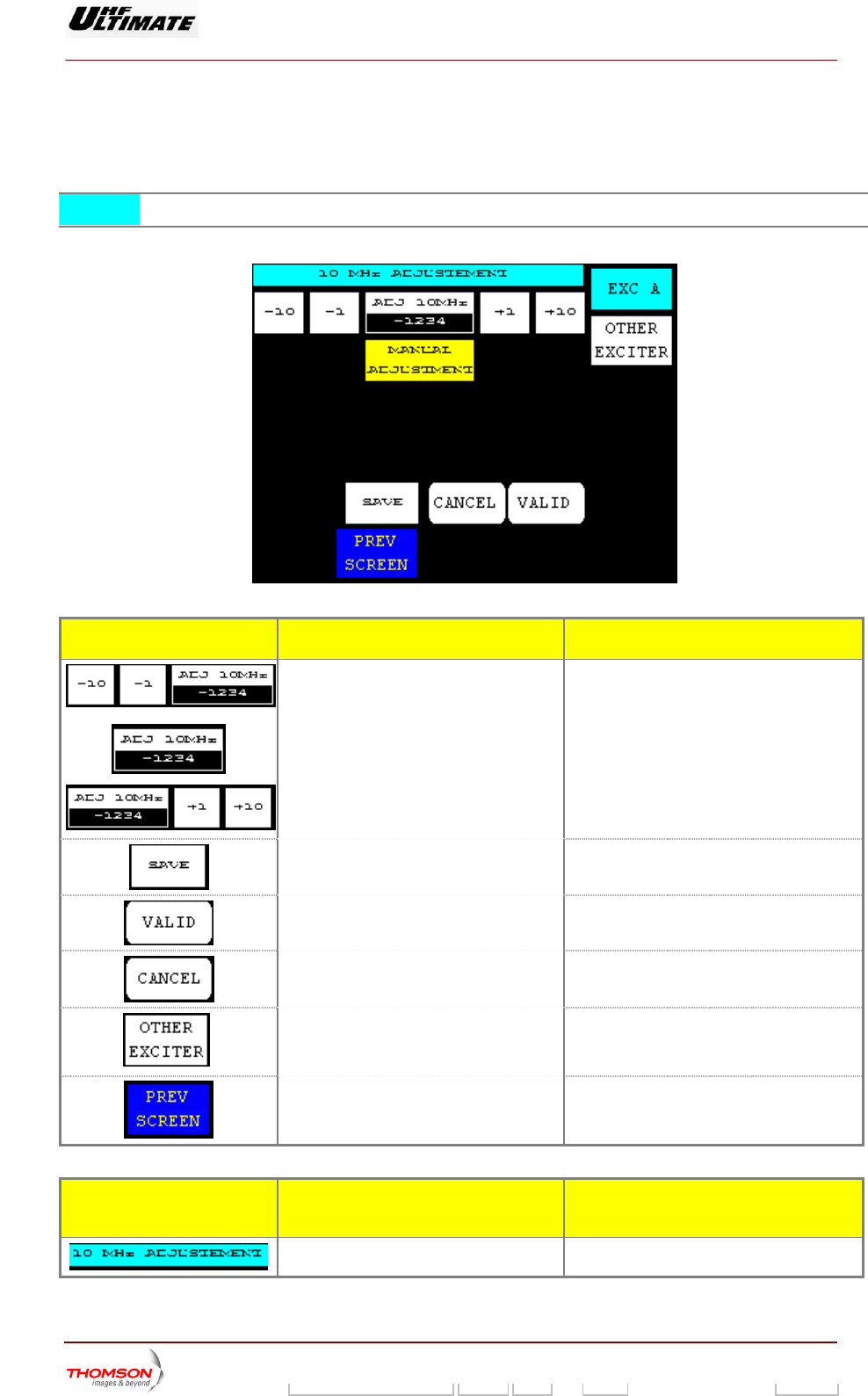
2.1.41. "10 MHz ADJUSTEMENT" window, SIRIUS version ONLY
This window is called up by pressing the "PLL 10MHz" control keys in the "SETTINGS" window.
NOTE: This window is available in SIRIUS version only.
This window is only available in Maintenance mode.
CONTROL KEYS FUNCTIONS DISPLAY/COMMENTS
Decrements the adjustment value of the
frequency 10Mhz internal by step of 1 or
by step of 10.
Displays the adjustment valu
frequency 10Mhz internal.
e of the
Increments the adjustment value of the
frequency 10Mhz internal by step of 1 or
by step of 10.
Allows to adjust the frequency 10MHz if the
choice " INTERNAL CLOCK " was selected,
we have then the message " MANUAL
ADJUSTMENT ".
The manual adjustment of the frequency is
possible whatever the state (present or
absent) in signals 1PPS or 10Mhz.
Allows saving adjustments above in the Flashes until the “SAVE”” command is either
validated or cleared.
basic transmitter.
Validates a selection.
Cancels a selection.
Calls up data from the other exciter. (*)
Calls up the "SETTING" window.
INDICATOR LAMPS AND
MESSAGE DISPLAYS
FUNCTIONS DISPLAY/COMMENTS
Gives the window name.
9932 V2
45321648.01 108 B E Checked 144 / 192
Numéro / Number Doc. Rev. Lan
g
u. 27/06/2006 Pa
g
e
Digital Liquid Cooled UHF
TV Equipment
Use of commands and description of indicators
Information contained is this document is confidential, is THOMSON property and cannot be disclosed in whatever form without prior written authorization of THOMSON.
IND ND ICATOR LAMPS A
MESSAGE DISPLAYS
FUNCTIONS DISPLAY/COMMENTS
Indicates which exciter data are displayed.
(*).
EXC A / EXC B
Displays the status of 10 Mhz adjustment
according to the clock configuration
chosen for the exciter (“Modulator
configuration” window)
MANUAL ADJUSTMENT /
AUTO ADJUSTMENT
♦ MANUAL ADJUSTMENT: The choice of
operating " INTERNAL CLOCK " has
been selected.
♦ AJUSTEMENT AUTO : The choice of
operating " EXTERNAL GPS or
EXTERNAL CLOCK " has been selected.
So control keys of this window are without
action.
(*) : Only Dual-Drive version.
9932 V2
45321648.01 108 B E Checked 145 / 192
Numéro / Number Doc. Rev. Lan
g
u. 27/06/2006 Pa
g
e
Digital Liquid Cooled UHF
TV Equipment
Use of commands and description of indicators
Information contained is this document is confidential, is THOMSON property and cannot be disclosed in whatever form without prior written authorization of THOMSON.
the "SETTINGS" window.
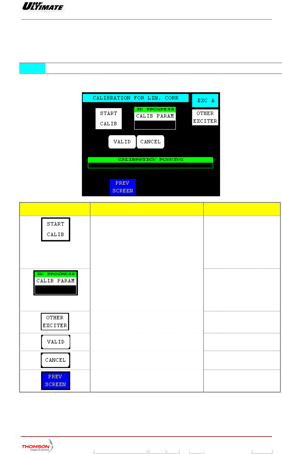
2.1.42. "LINEAR CORRECTION CALIBRATION" window, SIRIUS version ONLY
This window is called up by pressing the "LIN COR CALIB." control keys in
NOTE : This window is available in SIRIUS version only.
This window is avail
of Exciter A or B.
able in Maintenance mode only. It allows calibrating the linear correction feedback
CONTROL KEYS FUNCTIONS DISPLAY/COMMENTS
Starts the correction of the Linear correction BECAREFULL:
y et
calibration.
Achieve assembling electrical
circuit before
Pressing this control ke
validation allows to start the
Duration of the Calibration. 3 to 5
minutes
Selects the calibration coefficients of the lin
correction
y and
♦ SAVE: Allows saving actual
ear Press this control ke
validation:
coefficients into table.
♦ RECALL: Recalls the
coefficients of the last save
Calls up data from the other exciter. (*)
Validates a selection.
Cancels a selection.
Calls up the "SETTING" window.
9932 V2
45321648.01 108 B E Checked 146 / 192
Numéro / Number Doc. Rev. Lan
g
u. 27/06/2006 Pa
g
e
Digital Liquid Cooled UHF
TV Equipment
Use of commands and description of indicators
Information contained is this document is confidential, is THOMSON property and cannot be disclosed in whatever form without prior written authorization of THOMSON.
IND ND ICATOR LAMPS A
MESSAGE DISPLAYS
FUNCTIONS DISPLAY/COMMENTS
Gives the window name.
(*)
Indicates which exciter data are displayed. EXC A / EXC B
Displays the calibration progress.
: Only Dual-Drive version.
(*)
9932 V2
45321648.01 108 B E Checked 147 / 192
Numéro / Number Doc. Rev. Lan
g
u. 27/06/2006 Pa
g
e
Digital Liquid Cooled UHF
TV Equipment
Use of commands and description of indicators
Information contained is this document is confidential, is THOMSON property and cannot be disclosed in whatever form without prior written authorization of THOMSON.
ndow.
Exciter A or B.
This windows is available in SFN mode only. It is not available in 8VSB modulator unit (ATSC
Transmitters).
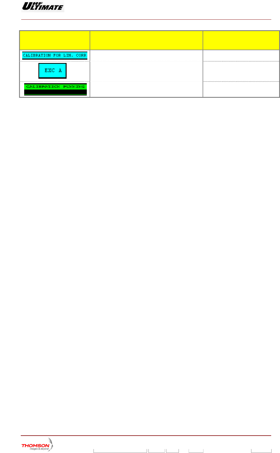
2.1.43. "SFN DELAY" window
This window is called up by pressing the "SFN" control keys in the "MODULATOR" wi
This windows displays the status of the delays necessary for SFN mode operation of
CONTROL KEYS FUNCTIONS DISPLAY/COMMENTS
(*)
Calls up data from the other exciter.
Calls up the "MODULATOR" window.
MESSAGES FUNCTIONS DISPLAY/COMMENTS
Gives the parameter name.
Indicates the SFN status. SFN ON / OFF
Indicates t GPS ON / OFF he GPS monitoring status.
Displays t
number.
he transmitter identification
Gives the
transmitter is in SFN mode.
parameter name when the
Displays the NETWORK delay value in
SFN mode.
This value can be changed by the MIP.
9932 V2
45321648.01 108 B E Checked 148 / 192
Numéro / Number Doc. Rev. Lan
g
u. 27/06/2006 Pa
g
e
Digital Liquid Cooled UHF
TV Equipment
Use of commands and description of indicators
Information contained is this document is confidential, is THOMSON property and cannot be disclosed in whatever form without prior written authorization of THOMSON.
MESSAGES FUNCTIONS DISPLAY/COMMENTS
Displays the EQUALISER delay value. This value is calculated by the modulator unit.
The different delays are related as follows :
Delays (MAX + OFFSET) =
Delays (NETWORK + EQUALISER +TRANSMITTER)
Displays the TRANSMITTER delay
value.
Displays the MAXIMUM delay value in
SFN mode.
This value can be changed by the MIP.
Displays the offset delay value w en
the transmitter is in SFN mode.
This value can be changed by the MIP and / or by
Local Control Panel window.
h
(*)
Indicates w
disp
EXC A / EXC B hich exciter data are
layed.
(*) : Dual-Drive version only.
9932 V2
45321648.01 108 B E Checked 149 / 192
Numéro / Number Doc. Rev. Lan
g
u. 27/06/2006 Pa
g
e
Digital Liquid Cooled UHF
TV Equipment
Use of commands and description of indicators
Information contained is this document is confidential, is THOMSON property and cannot be disclosed in whatever form without prior written authorization of THOMSON.
2.1.44. "MODULATOR
This window is called up b t
It displays the status of the DVB-T nfiguration parame
is available with an internal
CONFIG" window
y pressing the "CONFIG" control keys in
modulator co
he "MODULATOR" window.
ters of exciter A or B. This window
COFDM modulator only (DVB-T Transmitters).
CONTROL KEYS FUNCTIONS DISPLAY/COMMENTS
(*)
Calls up data from the other exciter.
Calls up the "MODULATOR" window.
(*) : Only Dual-Drive version
INDICATOR LAMPS AND
MESSAGE DISPLAYS
FUNCTIONS DISPLAY/COMMENTS
Gives the window name.
Displays the constellation type used by the
modulator.
CONSTEL 64-QAM/16-QAM/QPSK
64-QAM : 64-bit representation
16-QAM : 16-bit representation
QPSK (4-QAM) : 4-bit representation
Displays the band width. WIDTH 8 MHz / 7 MHz / 6 MHz
Displays the guard interval used by the
COFDM modulator.
INTERVAL 1/32; 1/16; /1/8; 1/4
Displays the High Priority code rate of the
modulation.
HP CODE RATE 7/8; 5/6; 3/4; 2/3; 1/2
Displays the number of transmitted carriers. CARRIER 8K / 2K
Displays the input configuration of the
modulator.
Data PRBS 15, Data PRBS 17, Data PRBS
20, Data PRBS 23, Data input ASI, Data
DVB_SPI
9932 V2
45321648.01 108 B E Checked 150 / 192
Numéro / Number Doc. Rev. Lan
g
u. 27/06/2006 Pa
g
e
Digital Liquid Cooled UHF
TV Equipment
Use of commands and description of indicators
Information contained is this document is confidential, is THOMSON property and cannot be disclosed in whatever form without prior written authorization of THOMSON.
INDICATOR LAMPS AND
MESSAGE DISPLAYS
FUNCTIONS DISPLAY/COMMENTS
Displays the configuration of the MODAP
clock.
CLOCK internal, CLOCK external, CLOCK
data derived
(*)
Indicates which exciter data are displayed. EXC A / EXC B
(*) : Only Dual-Drive version
9932 V2
45321648.01 108 B E Checked 151 / 192
Numéro / Number Doc. Rev. Lan
g
u. 27/06/2006 Pa
g
e
Digital Liquid Cooled UHF
TV Equipment
Use of commands and description of indicators
Information contained is this document is confidential, is THOMSON property and cannot be disclosed in whatever form without prior written authorization of THOMSON.
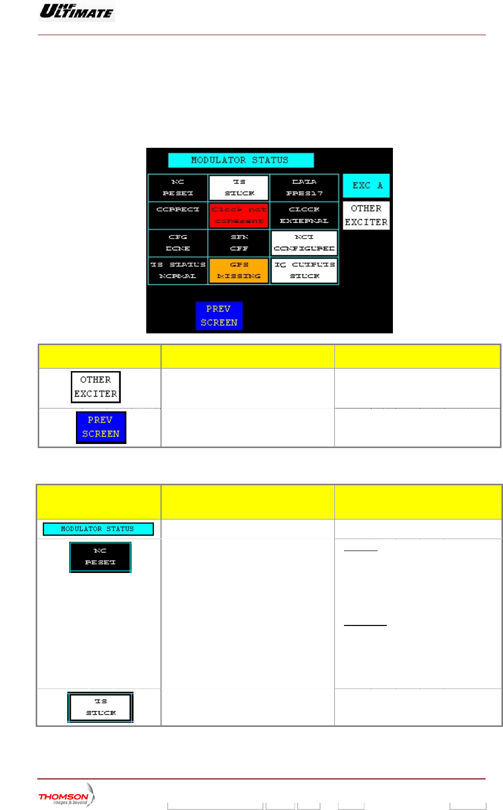
2.1.45. "MODULATOR
This window is called up b e "MODULATOR" window.
It displays the status of the DVB-T ation parameters of exciter A or B. This window
is only available with an internal COFDM modulator (DVB-T Transmitters).
STATUS" window
y pressing the "STATUS" control keys in th
modulator configur
CONTROL KEYS FUNCTIONS DISPLAY/COMMENTS
(*)
Calls up data from the other exciter.
Calls up the "MODULATOR" window.
(*): Only Dual-Drive version
INDICATOR LAMPS AND
MESSAGE DISPLAYS
FUNCTIONS DISPLAY/COMMENTS
Gives the window name.
Displays the Reset status of the modulator. "No Reset" is displayed when:
the internal COFDM modulator has not
been affected by a mains failure.
the internal COFDM modulator has not
been affected by a reset which was not
commanded by the DAP unit.
"Reset Done" is displayed when:
the internal COFDM modulator has been
affected by a reset which was not
commanded by the DAP unit.
the COFDM power supply is shut down, but
the DAP power supply is present.
Displays the input interface status of the
modulator.
TS (interface) toggling /
TS (interface) stuck
9932 V2
45321648.01 108 B E Checked 152 / 192
Numéro / Number Doc. Rev. Lan
g
u. 27/06/2006 Pa
g
e
Digital Liquid Cooled UHF
TV Equipment
Use of commands and description of indicators
Information contained is this document is confidential, is THOMSON property and cannot be disclosed in whatever form without prior written authorization of THOMSON.
INDICATOR LAMPS AND
MESS GE DISPLAYS A
FUNCTIONS DISPLAY/COMMENTS
Displays the input signal of the modulator. Data PRBS 15 / Data PRBS 17 / Dat
PRBS 20 / Data PRBS 23 / Data input ASI /
a
Data DVB_SPI
Displays the internal status of the modulator. Correct / Internal fault
Displays the synchronisation status of the
clock with respect to the Transport Stream.
Clock coherent / PLL unlocked / Clock not
coherent
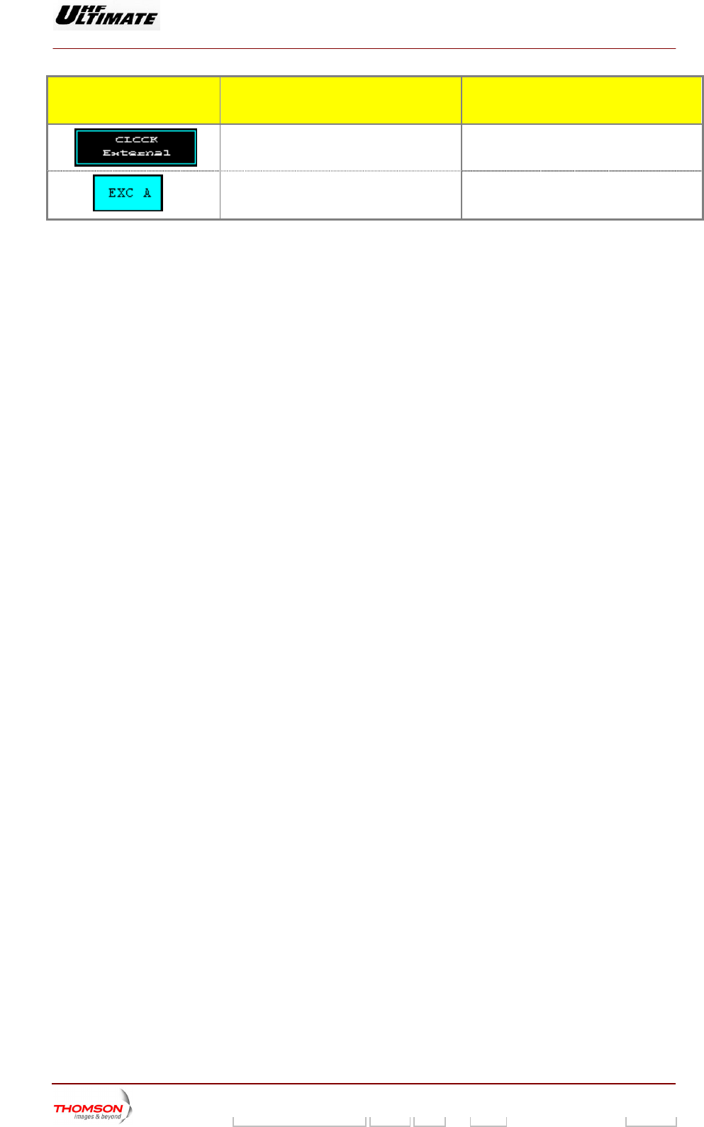
Displays the type of clock used. CLOCK internal, CLOCK external, CLOCK
data derived
Displays the status of configuration. CFG done / CFG underway / CFG fault
Displays the SFN mode operation.status SFN ON / SFN OFF
Displays the status of the modulator. Not configured / Configured / CFG fault
Not configured :
The modulator does not accept the
requested configuration.
Displays the atus. TS status normalTransport Stream st / abnormal
Displays the GPS status. GPS missing / GPS présent
GPS missing :
The 10 MHz and/or 1 PPS reference
sign
als are missing.
Displays the output interface status o
modulator.
f the IQ outputs toggling /
IQ outputs stuck
(*)
Indicates which exciter data are display A / EXC B ed. EXC
(*) : Only Dual-Drive versio
n.
9932 V2
45321648.01 108 B E Checked 153 / 192
Numéro / Number Doc. Rev. Lan
g
u. 27/06/2006 Pa
g
e
Digital Liquid Cooled UHF
TV Equipment
Use of commands and description of indicators
Information contained is this document is confidential, is THOMSON property and cannot be disclosed in whatever form without prior written authorization of THOMSON.
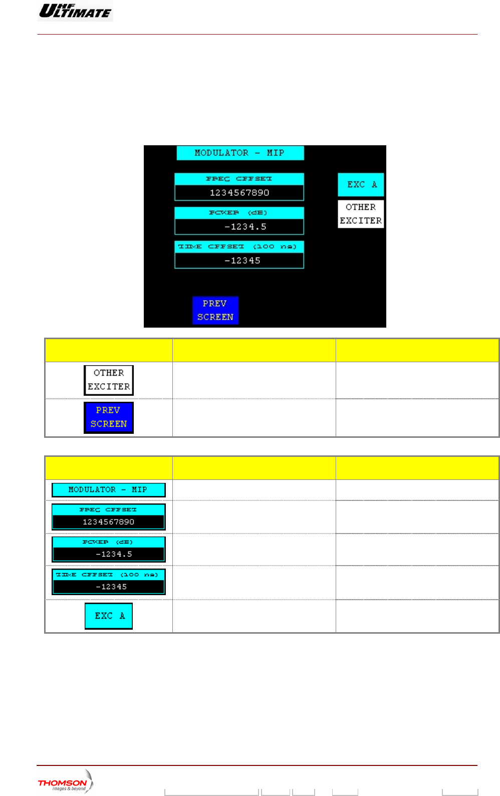
2.1.46. "MODULATOR - MIP" window
This window is called up b i
This window displays the ntained in the Trans
SFN mode only. It isn’t available in 8VSBB modulator unit (A smitters).
y pressing the "MIP" control keys
MIP data co
n the "MODULATOR" window.
port Stream. This windows is available in
TSC Tran
CONTROL KEYS FUNCTIONS DISPLAY/COMMENTS
Calls up data from the other exciter. (*)
Calls up the "MODULATOR" window.
MESSAGE FUNCTIONS DISPLAY/COMMENTS
Gives the window name.
Displays the RF synthesizer frequency
offset value.
Displays the output RF power offset value. The typical output power level is 0 dB
(value of the required power).
Displays the offset delay value contained
in the MIP when the transmitter is in SFN
mode.
Indicates which exciter data are
displayed.(*)
EXC A / EXC B
(*) : Only Dual-Drive version.
9932 V2
45321648.01 108 B E Checked 154 / 192
Numéro / Number Doc. Rev. Lan
g
u. 27/06/2006 Pa
g
e
Digital Liquid Cooled UHF
TV Equipment
Use of commands and description of indicators
Information contained is this document is confidential, is THOMSON property and cannot be disclosed in whatever form without prior written authorization of THOMSON.
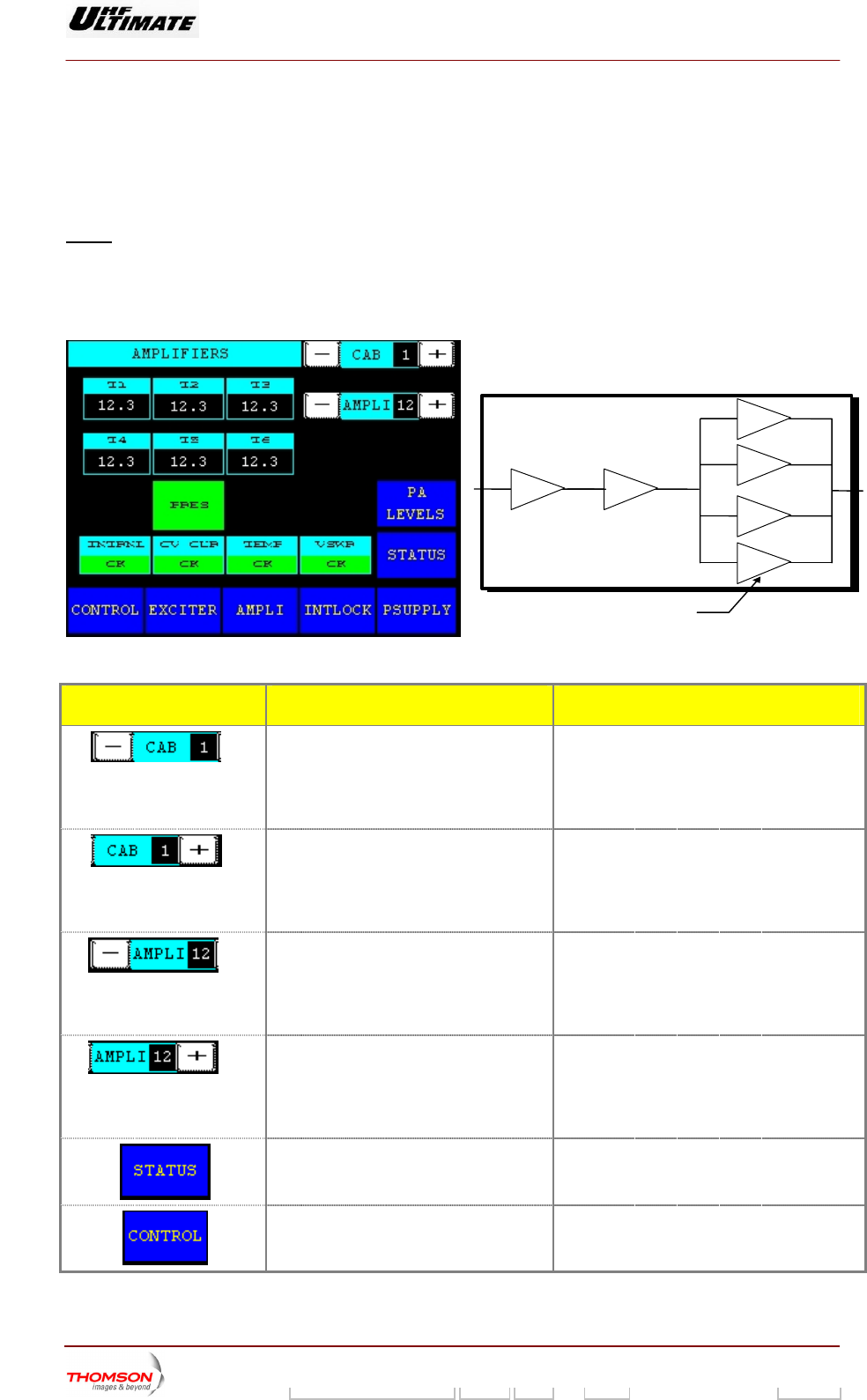
2.1.47. "RF AMPLIFIERS" window, 6 current values (OPTIMUN / ULTIMATE FAMILY)
This window is called up by the "AMPLI" command in the other windows.
It displays the status of an RF amplifier.
Notes : An amplifier which is not included in the transmitter configuration can not be
accessed by the keys "± AMPLI".
A cabinet which is not included in the transmitter configuration can not be
accessed by the "± CAB" co
ntrol keys.
T1
T2
T3
T4
T5T6
POWER AMPLIFIER
Amplifier modules
With transistors
CONTROL KEYS FUNCTIONS DISPLAY/COMMENTS
(*)
Decrements the cabinet number. The number resulting from the decrêmentation
is displayed in the message window bet een
the "+ CAB" and "- CAB" control keys.
mmand is disabl while the PCL is locked
w
Co
(d
ed
isabled).
(*)
The numbe
is between
th eys.
ommand is disabled while the PCL is locked
isabled).
Increments the cabinet number. r resulting from the incrementation
displayed in the message window
e "+ CAB" and "- CAB" control k
C
(d
(**)
Decrements the amplifier number in a
particular cabinet.
T crementation
is display
th
hile the PCL is locked
isabled).
he number resulting from the de
ed in the message window between
e "+ AMPLI" and "- AMPLI" control keys.
Command is disabled w
(d
(**)
Increments the amplifier number in a
particular cabinet.
T
is
th
C the PCL is locked
he number resulting from the incrementation
displayed in the message window between
e "+ AMPLI" and "- AMPLI" control keys.
ommand is disabled while
(disabled).
Calls up the "TRA
NSMITTER STATUS"
window.
Calls up the "CONTROL Level 1" window.
9932 V2
45321648.01 108 B E Checked 155 / 192
Numéro / Number Doc. Rev. Lan
g
u. 27/06/2006 Pa
g
e