Thomson Broadcast and Multimedia ULT-1K10K2 UHF Digital transmitter, for use with MediaFlo User Manual PREIMPAP
Thomson Broadcast & Multimedia, Inc. UHF Digital transmitter, for use with MediaFlo PREIMPAP
Contents
User Manual part 3
Digital Liquid Cooled UHF
TV Equipment
Use of commands and description of indicators
Information contained is this document is confidential, is THOMSON property and cannot be disclosed in whatever form without prior written authorization of THOMSON.
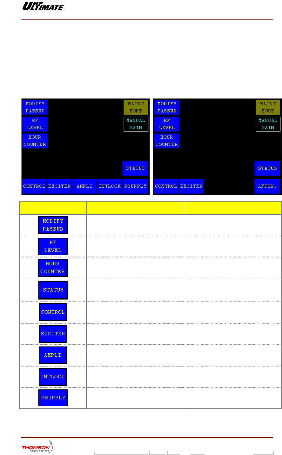
2.1.13. "CONTROL OPER Level 2" window for Normal Mode
OPTIMUM FAMILY OR ULTIM
This window is called up by pressing the "NEXT CONTROL" control keys in the "CONTROL Level 1"
window when the transmitter is in normal mode.
It provides access to a restricted number of commands and information and is only available in Normal
Mode.
ATE FAMILY AFFINTY FAMILY
CONTROL KEYS FUNCTIONS DISPLAY/COMMENTS
Calls up the "MODIFY PASSWD" window. Command is disabled while the PCL is
locked (disabled).
Calls up the "RF LEVEL" window.
Calls up the "HOUR COUNTER" window.
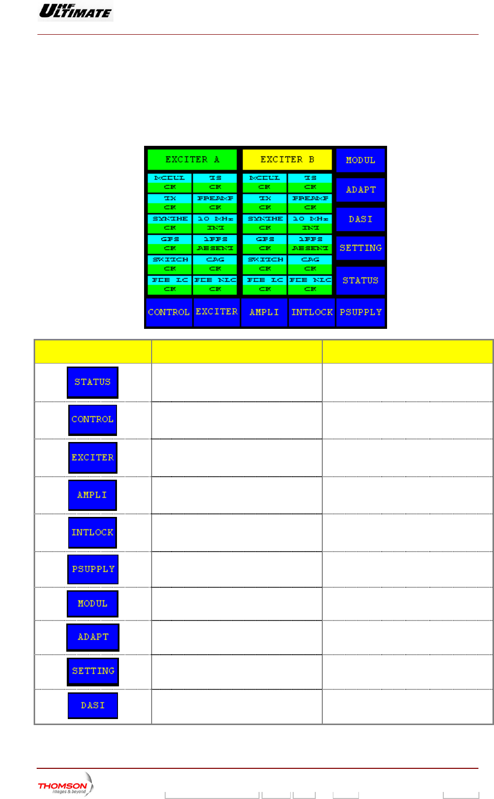
Calls up the "STATUS" window.
Calls up the "CONTROL Level 1" window.
Calls up the "EXCITER Level 1" window.
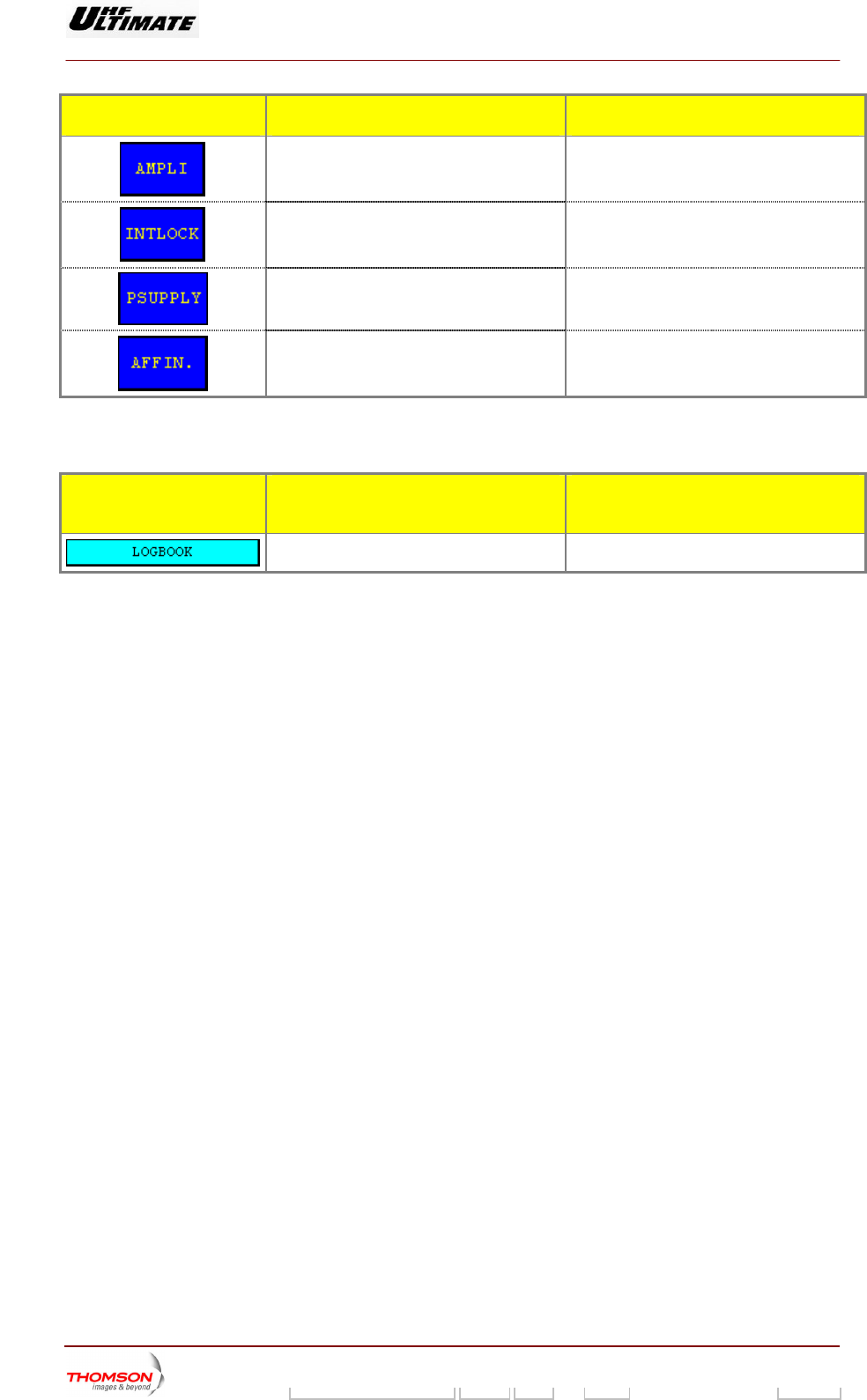
Calls up the "AMPLIFIERS" window. (a)
Calls up the «INTERLOCK» window (a)
Calls up the "POWER SUPPLY" window. (a)
9932 V2
45321648.01 108 B E Checked 78 / 192
Numéro / Number Doc. Rev. Lan
g
u. 27/06/2006 Pa
g
e
Digital Liquid Cooled UHF
TV Equipment
Use of commands and description of indicators
Information contained is this document is confidential, is THOMSON property and cannot be disclosed in whatever form without prior written authorization of THOMSON.
CONTROL KEYS FUNCTIONS DISPLAY/COMMENTS
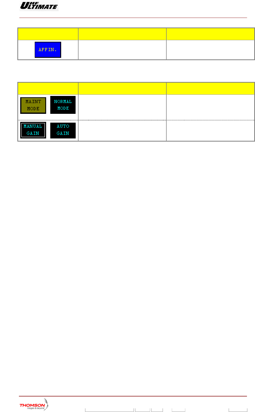
p the "AFFINITY" window. (b) Calls u
(a): Not Visible for AFFINITY family
(b): Not Visible for OPTIMUM or ULTIMATE families
MESSAGE FUNCTIONS DISPLAY/COMMENTS
/
Displays the current operating mode of the
transmitter (maintenance mode or normal
mode)
Th
mu
i ing message to indicate that the
maintenance mode is operating.
. Bl
e "NORMAL MODE" message window
st be displayed.
nk
Displays, which gain control mode (manual
or aut by the
transm
AUTO GAIN / MANUAL GAIN
/
omatic) is currently picked up
itter.
9932 V2
45321648.01 108 B E Checked 79 / 192
Numéro / Number Doc. Rev. Lan
g
u. 27/06/2006 Pa
g
e
Digital Liquid Cooled UHF
TV Equipment
Use of commands and description of indicators
Information contained is this document is confidential, is THOMSON property and cannot be disclosed in whatever form without prior written authorization of THOMSON.
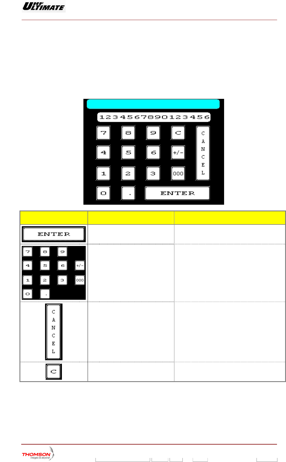
2.1.14. "NUMERICAL VALUE" window
This window is call d up a
♦ a request to change pa s
♦ an enter password com nge password command
It is used to input data.
e fter:
rameters from one of the PCL window
mand or a cha
,
.
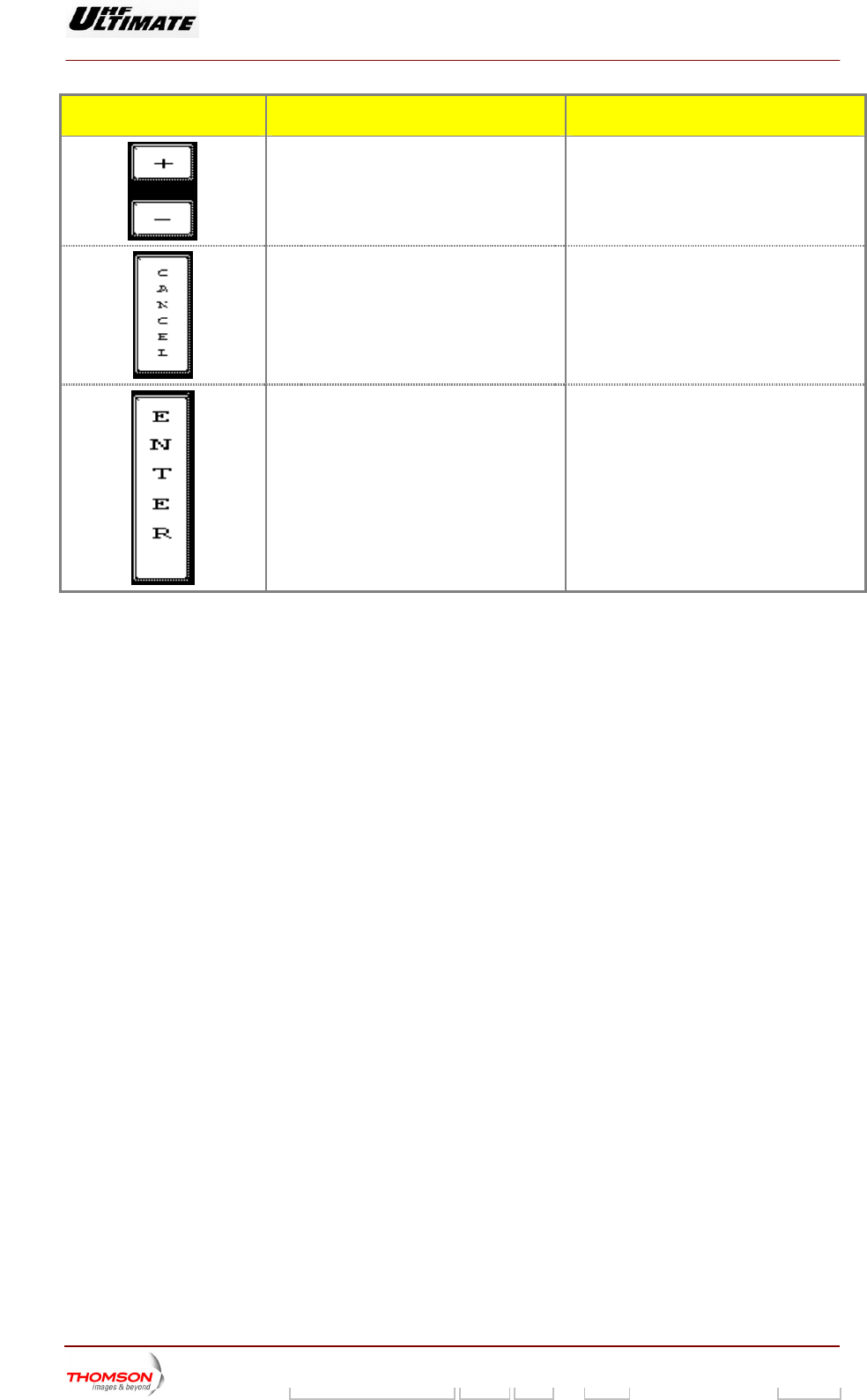
CONTROL KEYS FUNCTIONS DISPLAY/COMMENTS
Validates the entry and calls back the
previous wi
ndow.
Used to insert parameter value.
Numeric keys.
Cancels the entry and calls back the
previous window.
Cancels the last digit entry.
9932 V2
45321648.01 108 B E Checked 80 / 192
Numéro / Number Doc. Rev. Lan
g
u. 27/06/2006 Pa
g
e
Digital Liquid Cooled UHF
TV Equipment
Use of commands and description of indicators
Information contained is this document is confidential, is THOMSON property and cannot be disclosed in whatever form without prior written authorization of THOMSON.
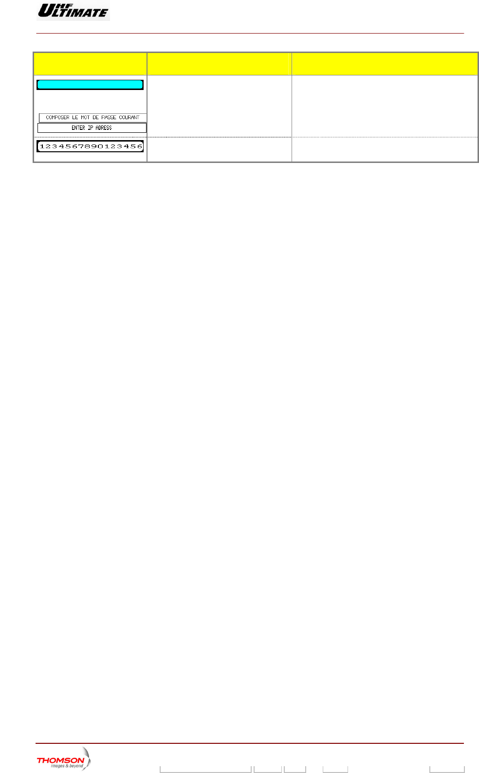
MESSAGE FUNCTIONS DISPLAY/COMMENTS
Shows the window title. The title shows the name of the selected
parameter.
Examples:
Displays the value of the parameter
during entry.
When entering a password, an asterix (*) is
displayed each time a numeric key is pressed.
9932 V2
45321648.01 108 B E Checked 81 / 192
Numéro / Number Doc. Rev. Lan
g
u. 27/06/2006 Pa
g
e
Digital Liquid Cooled UHF
TV Equipment
Use of commands and description of indicators
Information contained is this document is confidential, is THOMSON property and cannot be disclosed in whatever form without prior written authorization of THOMSON.
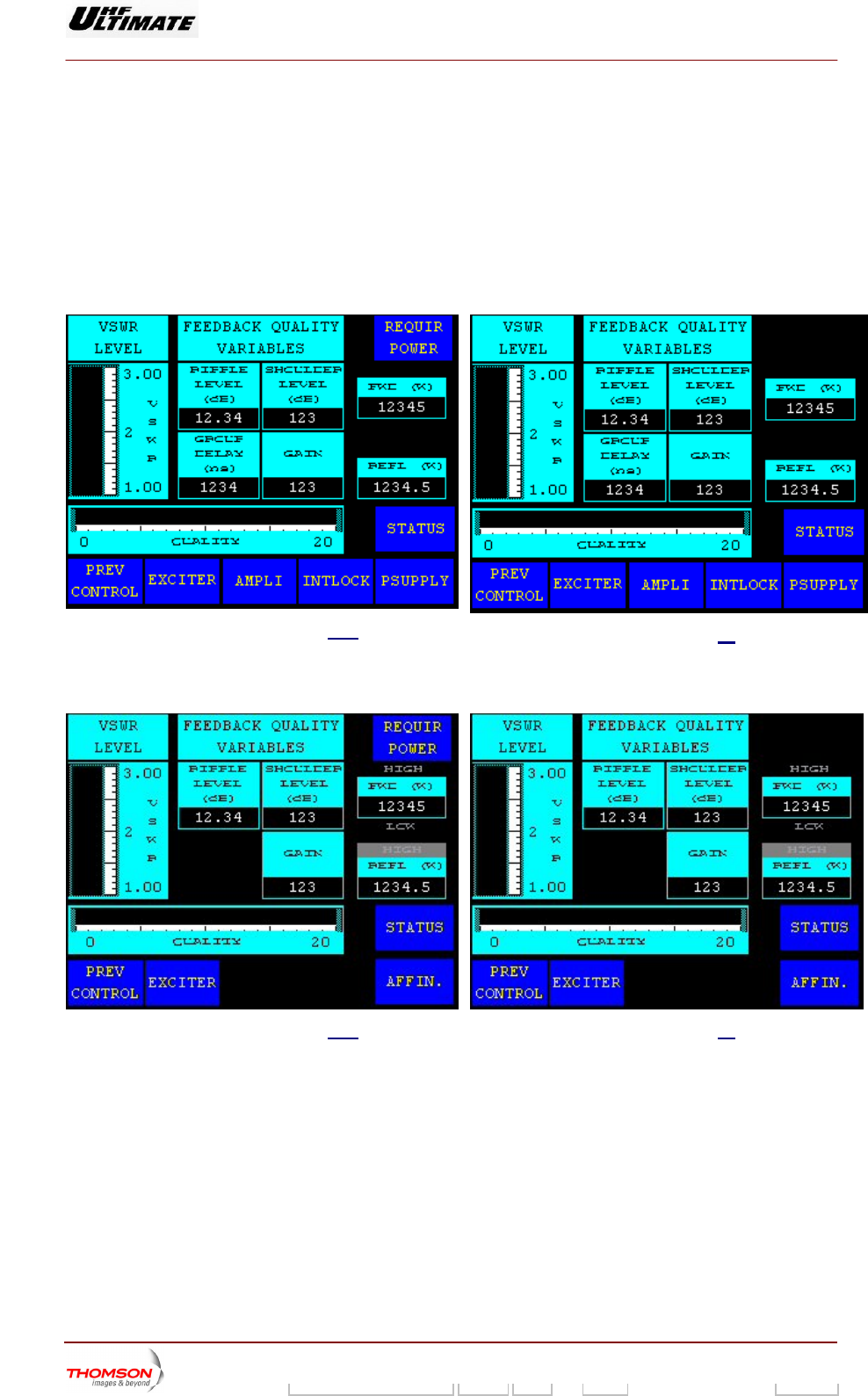
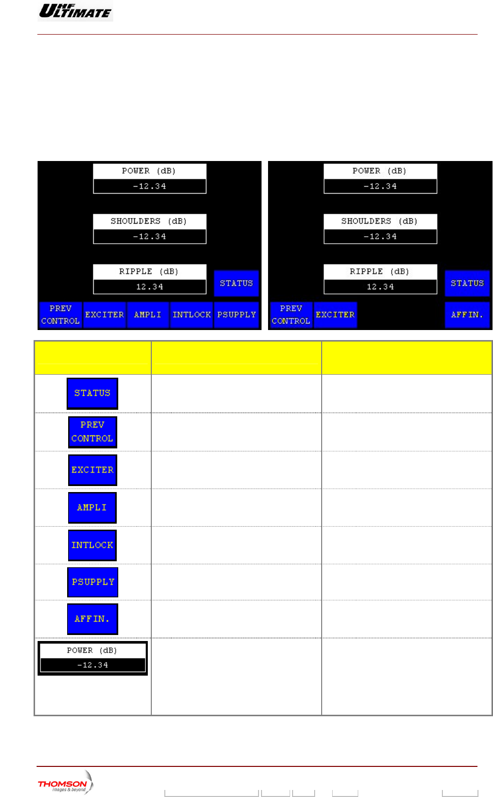
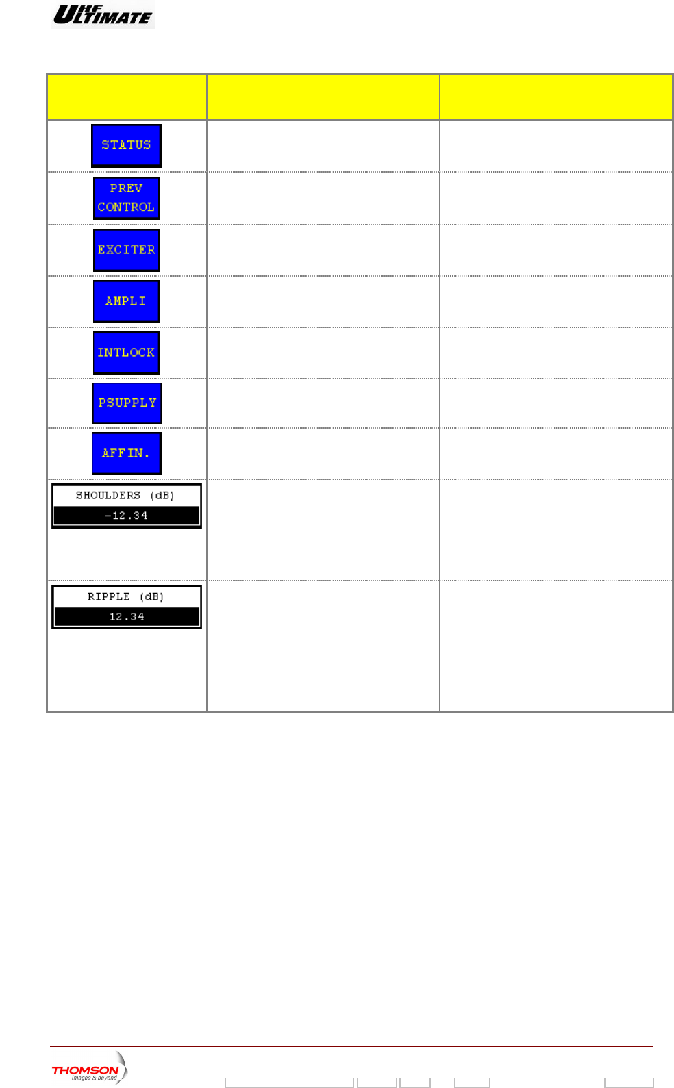
2.1.15. "RF LEVEL" window
This window is called up EL" control keys in either the "CONTROL MAINT Level 2"
window or the "CONTROL OPER Level 2" window.
This window displays the reflected and forward power values, as well as the quality variables of the RF
feedback signal.
OPTIMUM FAMILY OR ULTIMATE FAMILY
by the "RF LEV
Figure 20 : Maintenance mode and MFN mode
operation Figure 21 : Normal mode or SFN mode
operation and MediaFLO modulator
AFFINTY FAMILY
Figure 22 : Maintenance mode and MFN mode
operation
Figure 23 : Normal mode or SFN mode
operation
9932 V2
45321648.01 108 B E Checked 82 / 192
Numéro / Number Doc. Rev. Lan
g
u. 27/06/2006 Pa
g
e
Digital Liquid Cooled UHF
TV Equipment
Use of commands and description of indicators
Information contained is this document is confidential, is THOMSON property and cannot be disclosed in whatever form without prior written authorization of THOMSON.
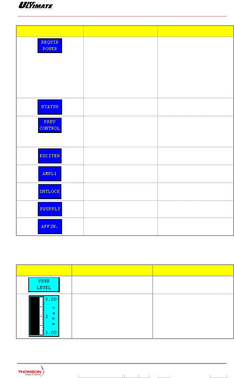
CONTROL KEYS FUNCTIONS DISPLAY/COMMENTS
Calls up the "REQUIRED POWER"
window. (3)
ATSC transmitter
This control keys is available in
Maintenance mode only.
Control key invisible in Normal mode only.
DVB-T transmitters
This control keys is available in
M nd MFN mode aintenance mode a
operation only.
Control key invisible in Normal mode or
SFN mode operation.
Calls up the "TRANSMITTER STATUS"
window.
Calls up windows as follows:
"CONTROL MAINT Level 2", if the
system is in maintenance mode,
"CONTROL OPER Level 2", if the
system is in normal mode.
Calls up the "EXCITER Level 1" window.
Calls up the "AMPLIFIERS" window. (a)
Calls up the «INTERLOCK» window (a)
Ca
lls up the "POWER SUPPLY" window.
(a)
Calls up the "AFFINITY" window. (b)
(a): Not Visible for AFFINIT
(b): Not Visible for OPTIMU
(3): Unavailable for MediaFLO modulator
Y family
M or ULTIMATE families
MESS GE AFUNCTIONS DISPLAY/COMMENTS
Gives the parameter name.
Displays the antenna SWR (before RF filter
unit).
9932 V2
45321648.01 108 B E Checked 83 / 192
Numéro / Number Doc. Rev. Lan
g
u. 27/06/2006 Pa
g
e
Digital Liquid Cooled UHF
TV Equipment
Use of commands and description of indicators
Information contained is this document is confidential, is THOMSON property and cannot be disclosed in whatever form without prior written authorization of THOMSON.
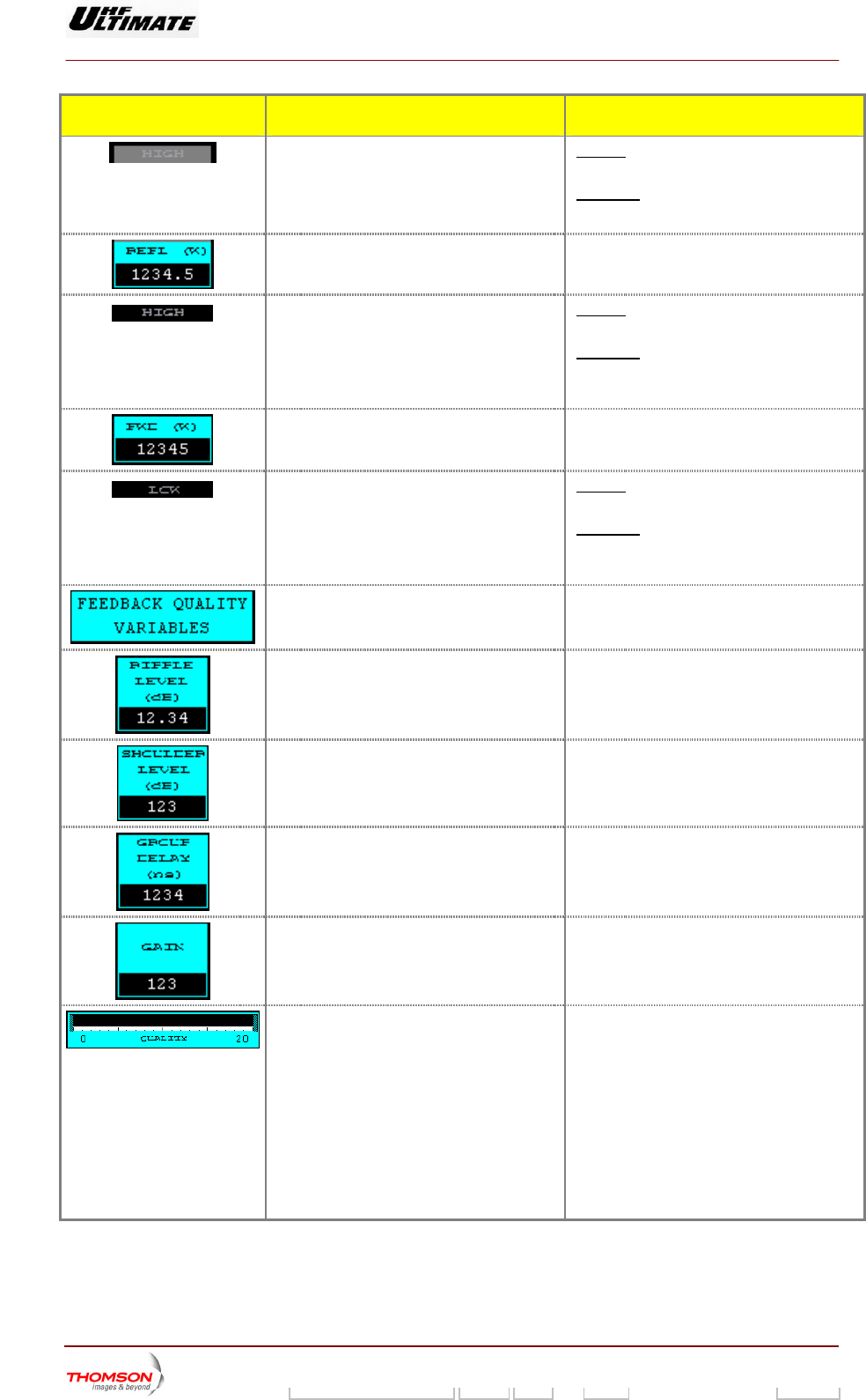
MESSAGE FUNCTIONS DISPLAY/COMMENTS
Indicates a higher value tha
value.
n the threshold ashes
Fl if the reflected power (reverse
wer) exceeds 3% of calibrated power
po
Otherwise not visible.
The threshold value (3%) is unchanging
Displays the reflected (reverse) RF power
value.
This value is expressed in watts or as a
percentage of calibrated power value
according with your installation choice
Indicates a higher value than the high alarm
threshold value.
Flashes if the transmitted power exceeds the
maximum power threshold value.
Otherwise not visible.
The alarm threshold is set using the «RF
THRESHOLD» window.
Displays the transmitted RF power value. This value is expressed in watts or as a
percentage of the calibrated power value
according with your installation choice
Indicates a lower value than the low alarm
threshold value.
Flashes if the transmitted power is lower
than the minimum power threshold value.
Otherwise not visible.
The alarm threshold is set using the «RF
THRESHOLD» window.
Gives the parameter name.
Displays the measured in-band ripple value. Available in Adaptive mode only.
Displays the measured shoulder level value. Available in Adaptive mode only.
Displays the measured group delay level
value (4).
Available in Adaptive mode only.
Displays the measured gain value. Available in Adaptive mode only.
The nominal value is 128.
Displays the calculated quality assessment
of the transmitter.
Available in Adaptive mode only.
The quality assessment depends on the
following measured parameters and quality
threshold levels :
♦ Power level
♦ Shoulder level
♦ Ripple level
The "QUALITY THRESHOLD SETTINGS"
window is accessible in installation mode.
(4): MediaFLO modulator only
9932 V2
45321648.01 108 B E Checked 84 / 192
Numéro / Number Doc. Rev. Lan
g
u. 27/06/2006 Pa
g
e
Digital Liquid Cooled UHF
TV Equipment
Use of commands and description of indicators
Information contained is this document is confidential, is THOMSON property and cannot be disclosed in whatever form without prior written authorization of THOMSON.
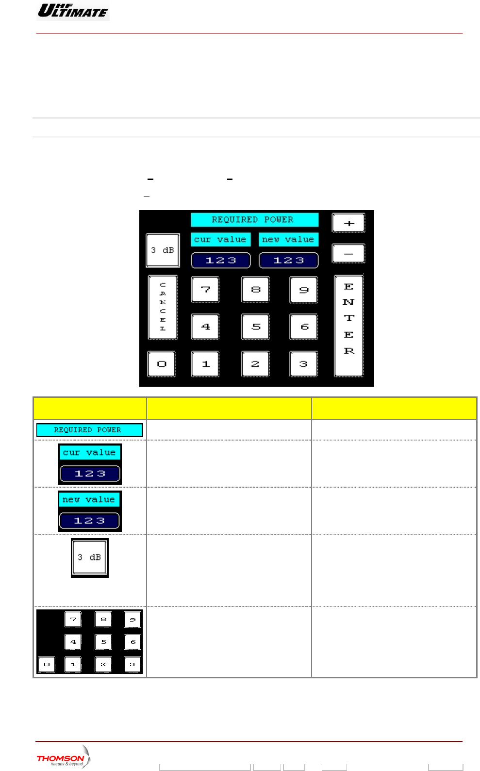
2.1.16. "REQUIRED POWER" window
.
odulator.
The «REQ PWR» controls key in either the «RF LEVEL» window or the «TRANSMITTER STATUS»
window calls it up when the transmitter is in maintenance mode
Note: This window is not available for MediaFlo m
This window is used to input the required Power. Th is the power level required by an operator (local
or remote). The operator can modify this level at any time. Range of variation :
♦ 0wer <
is
Required p
.25 * Calibred Po ower < 1.12 * Calibred Power
♦ With Required power < Maximum Power
CONTROL KEYS FUNCTIONS DISPLAY/COMMENTS
Shows the window title.
Displays the actual value of the required
power during entry.
Displays the value of th
during entry.
e required power efore selecting a new value to modify the
s is equal to current value.
B
value display
Selects a reduction in power
Displays last selection made by the operator
or by the system (automatic power
reduction).
0dB, 3dB, 6dB
For safety reasons, the PCL should be
locked when a power reduction to –3dB or –
6dB has been commanded.
Command is displayed while the PCL is
locked
Used to insert new value of required power.
Numeric keys.
9932 V2
45321648.01 108 B E Checked 85 / 192
Numéro / Number Doc. Rev. Lan
g
u. 27/06/2006 Pa
g
e
Digital Liquid Cooled UHF
TV Equipment
Use of commands and description of indicators
Information contained is this document is confidential, is THOMSON property and cannot be disclosed in whatever form without prior written authorization of THOMSON.
CONTROL KEYS FUNCTIONS DISPLAY/COMMENTS
Used to adjust slightly new value of required
power.
Cancels the entry and calls back the
previous window.
Validates the entry and calls back the
previous window.
9932 V2
45321648.01 108 B E Checked 86 / 192
Numéro / Number Doc. Rev. Lan
g
u. 27/06/2006 Pa
g
e
Digital Liquid Cooled UHF
TV Equipment
Use of commands and description of indicators
Information contained is this document is confidential, is THOMSON property and cannot be disclosed in whatever form without prior written authorization of THOMSON.
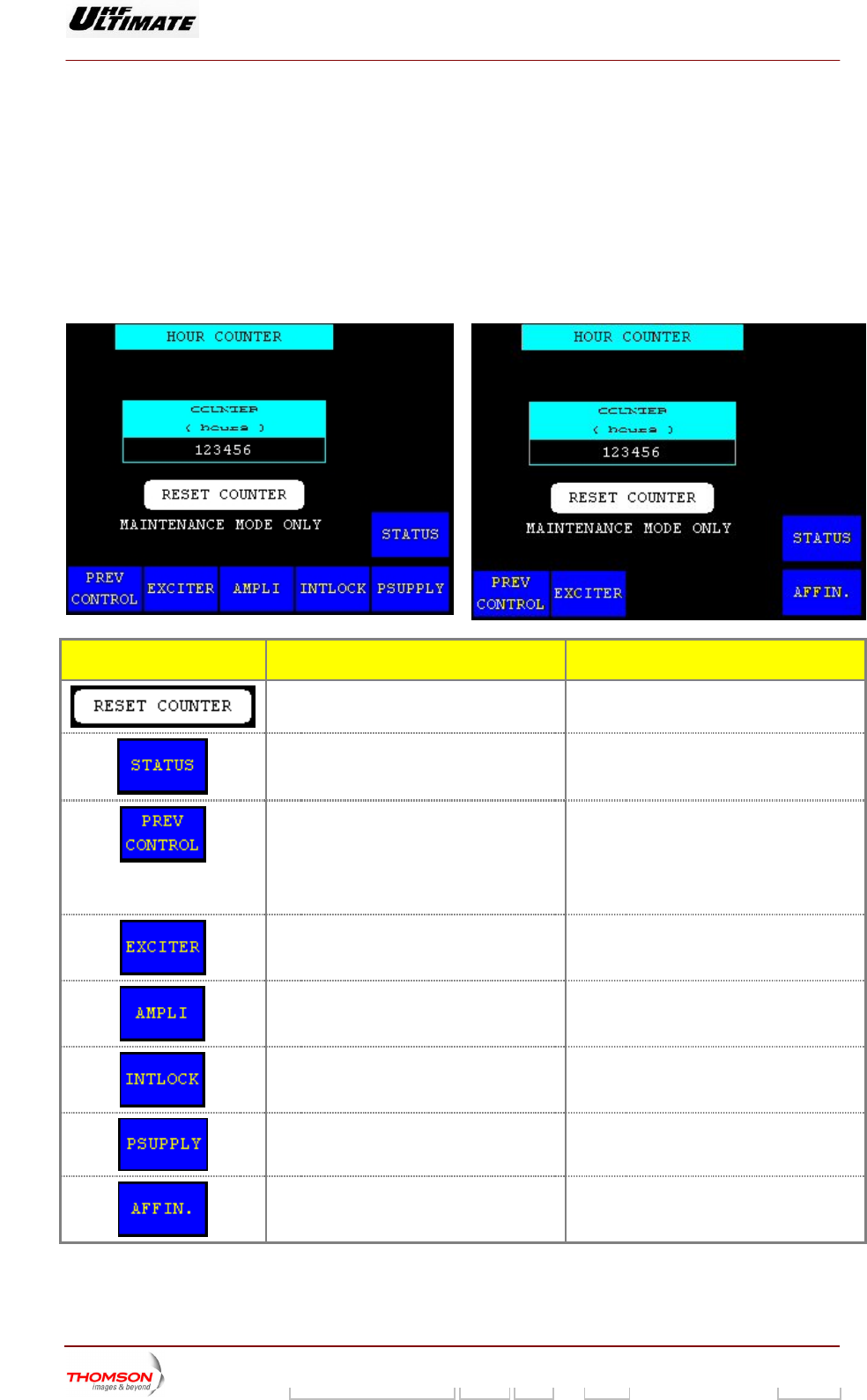
2.1.17. "HOUR COUNTER" window
This window is called up b ntrol keys in the "CONTROL MAINT
Level 2" window or in the " L OPER Level 2" window.
It displays a read-out of apsed time counter which shows the actual time during which the
transmitter has been in oper actual time during which the cooling
system has been in operati
OPTIMUM FA ILY OR ULTIMATE FAMILY
y pressing the "HOUR COUNTER" co
CONTRO
the el
ation. This value will also be the
on.
M
AFFINTY FAMILY
CONTROL KEYS FUNCTIONS DISPLAY/COMMENTS
Resets the elapsed time counter to zero. Command is disabled in Normal mode or
while the PCL is locked (disabled).
Calls up the "TRANSM
ITTER STATUS"
window.
Calls up windows as follows:
"CONTROL MAINT Level 2", if the system is
in maintenance mode,
"CONTROL OPER Level 2", if the system is
in normal mode.
Calls up the "EXCITER Level 1" window.
Calls up the "AMPLIFIERS" window. (a)
Calls up the «INTERLOCK» window (a)
Calls up the "POWER SUPPLY" window. (a)
Calls up the "AFFINITY" window. (b)
(a): Not Visible for AFFINITY family
(b): Not Visible for OPTIMUM or ULTIMATE families
9932 V2
45321648.01 108 B E Checked 87 / 192
Numéro / Number Doc. Rev. Lan
g
u. 27/06/2006 Pa
g
e
Digital Liquid Cooled UHF
TV Equipment
Use of commands and description of indicators
Information contained is this document is confidential, is THOMSON property and cannot be disclosed in whatever form without prior written authorization of THOMSON.
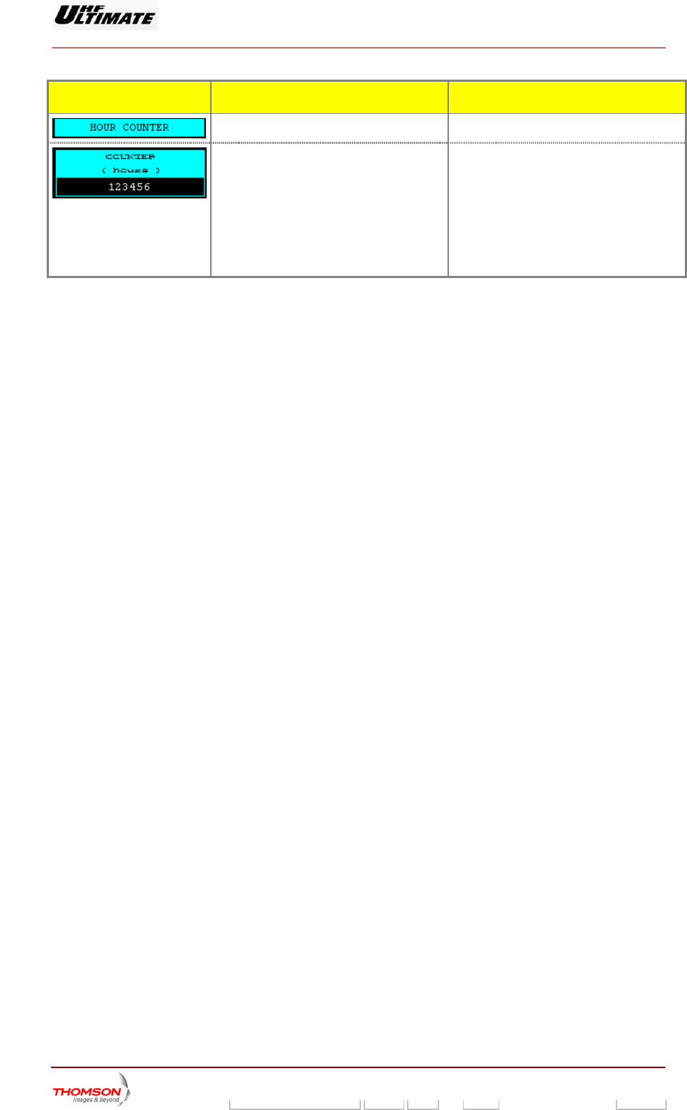
MESSAGE FUNCTIONS DISPLAY/COMMENTS
Gives the window name.
Displays the actual time during which The counter is reset to zero when the
" command in this
The in the CPU;
if the CPU i replaced, the counter
value will longer give a true
representation of the transmitter
operating time.
the transmitter has been in operation
since it was last reset.
"RESET COUNTER
window is activated.
counter value is stored
s
no
9932 V2
45321648.01 108 B E Checked 88 / 192
Numéro / Number Doc. Rev. Lan
g
u. 27/06/2006 Pa
g
e
Digital Liquid Cooled UHF
TV Equipment
Use of commands and description of indicators
Information contained is this document is confidential, is THOMSON property and cannot be disclosed in whatever form without prior written authorization of THOMSON.
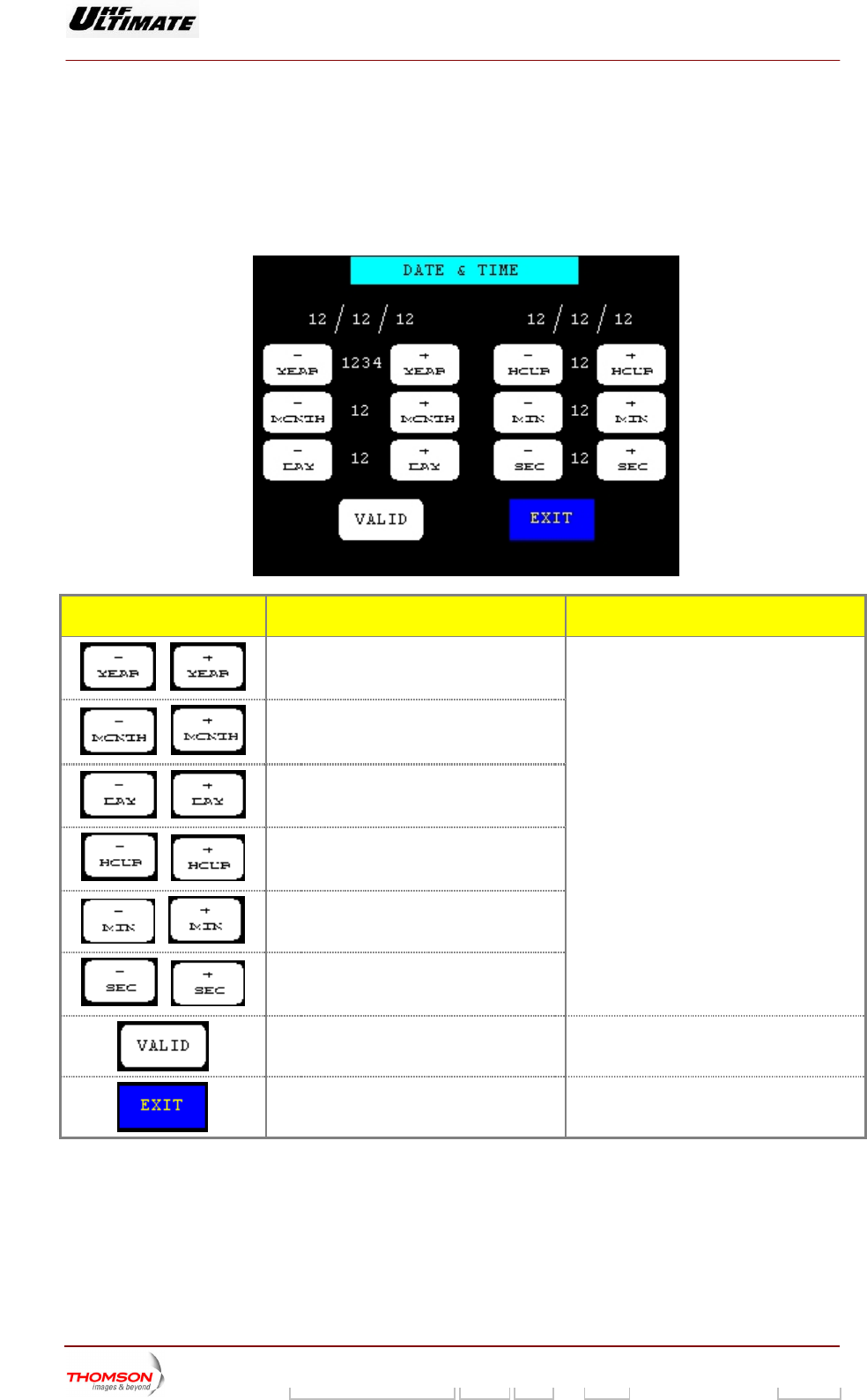
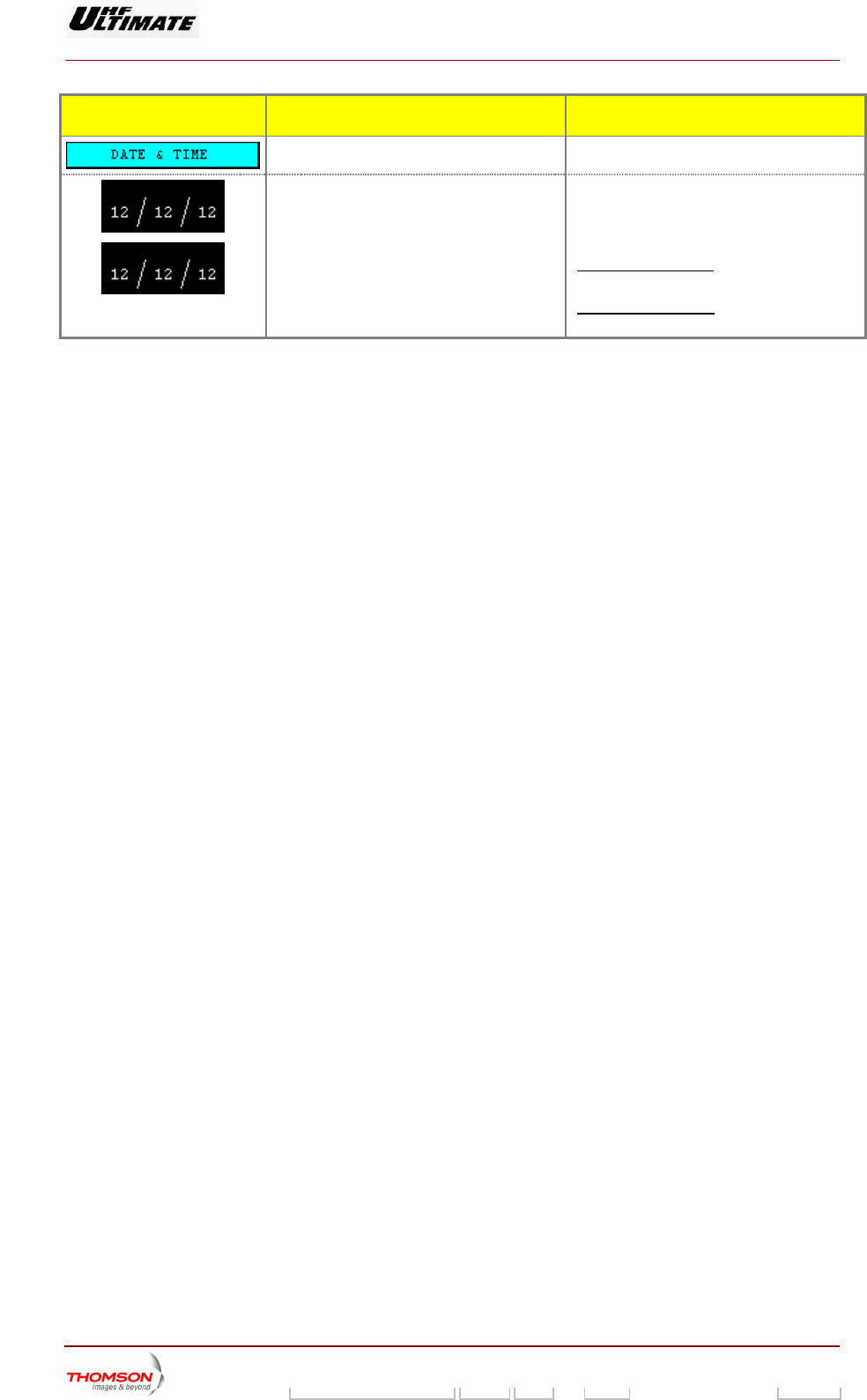
2.1.18. DATE & TIME" window
It is called up by pressing TROL MAINT Level 2" window. It is
only accessible when the transmitter is in maintenance mode.
This window i used to upd
the "DATE" control keys in the "CON
s ate the date and time.
CONTROL KEYS FUNCTIONS DISPLAY/COMMENTS
Increments or decremen
/
ts the year. These commands are locked out:
if the PCL is locked,
Increments
/
or decrements the month.
/
Increments or decrements the day.
/
Increments or decrements the hour.
/
Increments or decrements the minutes.
/
Increments or decrements the seconds.
while the number resulting from the
increment or decrement is being displayed
between the two control keys.
Validates the date and time displayed and
recalls the "CONTROL MAINT Level 2"
window.
Recalls the "CONTROL MAINT Level 2"
window without updating the date and time.
9932 V2
45321648.01 108 B E Checked 89 / 192
Numéro / Number Doc. Rev. Lan
g
u. 27/06/2006 Pa
g
e
Digital Liquid Cooled UHF
TV Equipment
Use of commands and description of indicators
Information contained is this document is confidential, is THOMSON property and cannot be disclosed in whatever form without prior written authorization of THOMSON.
MESSAGE FUNCTIONS DISPLAY/COMMENTS
Gives the window name.
Displays date and time values used by t
Central Control Unit.
he The date and time values are frozen to
values which correspond to the instant when
the "DATE" button in the "CONTROL MAINT
Level 2" window was pressed.
For ATSC transmitter, the display of
following : Month / Day / Year.
date is
For DVDT transmitter, the display of date is
following : Day / Month / Year.
9932 V2
45321648.01 108 B E Checked 90 / 192
Numéro / Number Doc. Rev. Lan
g
u. 27/06/2006 Pa
g
e
Digital Liquid Cooled UHF
TV Equipment
Use of commands and description of indicators
Information contained is this document is confidential, is THOMSON property and cannot be disclosed in whatever form without prior written authorization of THOMSON.
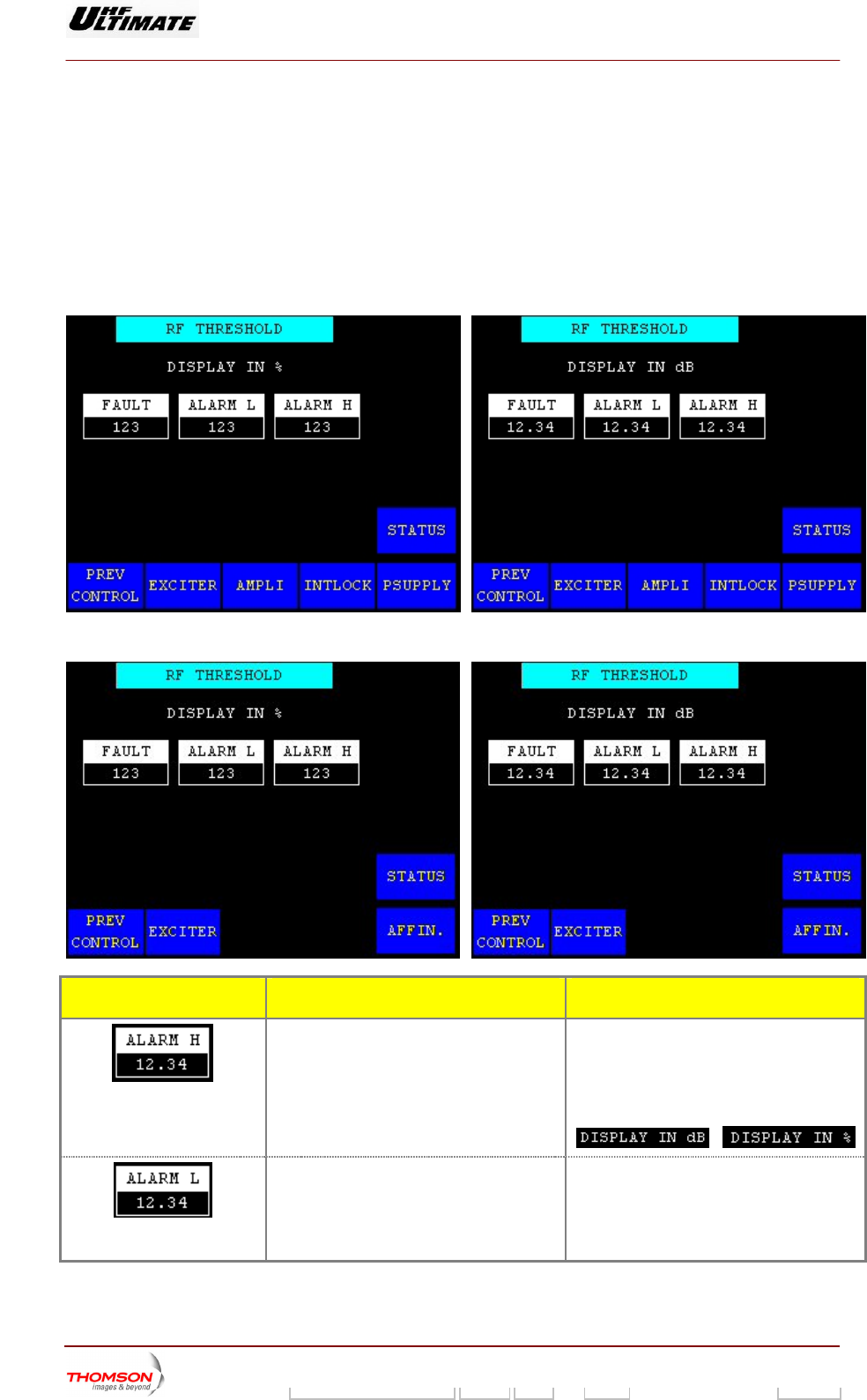
2.1.19. "RF THRESHOLD" window
This window is alled up by pr il 2"
window. It is only accessible in nce mode.
It provides for adjusting the thre ring the alarm a raw the
operator's attention to the RF power level status using the PCL "Alar
OR ULTIMATE FAMILY
c essing the "RF THRES" control keys
maintena
n the "CONTROL MAINT Leve
sholds for trigge nd fault signals which d
m" indicator lamp.
OPTIMUM FAMILY
AFFINTY FAMILY
CONTROL KEYS FUNCTIONS DISPLAY/COMMENTS
Calls up the "NUMERICAL VALUE" window
in w lue can
be c
Disp
pow
Commands are disabled while the PCL is
locked (disabled).
value is expressed in dB or as a
ntage of the calibrated power value
according with your installation choice
hich the high alarm threshold va
hanged.
lays the high alarm threshold for the RF
er level.
This
perce
/
Calls up the "NUMERICAL VALUE" window
in w
be changed.
Displays the low alarm threshold for the RF
pow
hich the low alarm threshold value can
er level.
9932 V2
45321648.01 108 B E Checked 91 / 192
Numéro / Number Doc. Rev. Lan
g
u. 27/06/2006 Pa
g
e
Digital Liquid Cooled UHF
TV Equipment
Use of commands and description of indicators
Information contained is this document is confidential, is THOMSON property and cannot be disclosed in whatever form without prior written authorization of THOMSON.
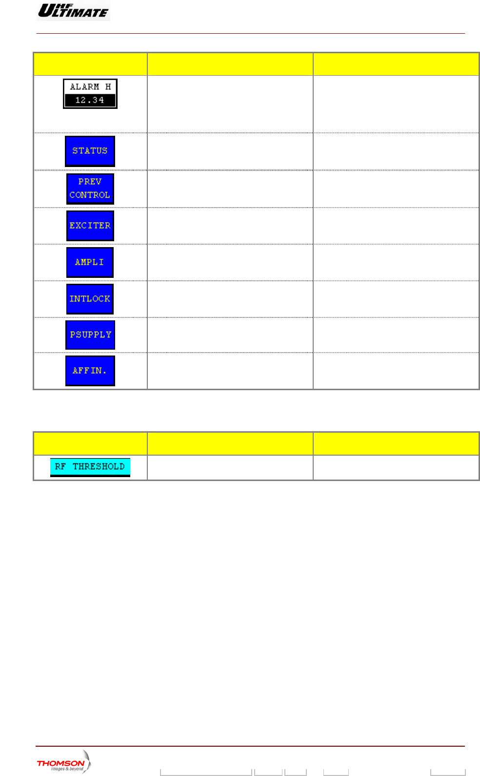
CONTROL KEYS FUNCTIONS DISPL S AY/COMMENT
Calls up the "NUMERICAL VALUE" window
in w
changed.
Displays the fault threshold for the RF power
leve
hich the fault threshold value can be
l.
Calls up the "STATUS" window.
Calls up the "CONTROL MAINT Level 2"
window.
Calls up the "EXCITER Level 1" window.
Calls up the "AMPLIFIERS" window. (a)
Calls up the «INTERLOCK» window (a)
Calls up the "POWER SUPPLY" window. (a)
Calls up the "AFFINITY" window. (b)
(a): Not Visible for AFFINITY family
(b): Not Visible for OPTIMUM or ULTIMATE families
MESSAGE FUNCTIONS DISPLAY/COMMENTS
Gives the window name.
9932 V2
45321648.01 108 B E Checked 92 / 192
Numéro / Number Doc. Rev. Lan
g
u. 27/06/2006 Pa
g
e
Digital Liquid Cooled UHF
TV Equipment
Use of commands and description of indicators
Information contained is this document is confidential, is THOMSON property and cannot be disclosed in whatever form without prior written authorization of THOMSON.
2.1.20. "QUALITY THRESHOLD SETTINGS" window
OPTIMUM FAMILY OR ULTIMATE FAMILY
It is called up by pressing the "QUALITY THRESHOLD" control keys in the " CONTROL MAINT
Level 2" window. It is only accessible in maintenance mode.
This window is used to change the quality threshold levels stored in the CPU card.
AFFINTY FAMILY
CONTROL KEYS FUNCTIONS SELECTIONS
AVAILABLE/COMMENTS
Calls up the "TRANSMITTER STATUS"
window.
Calls up the "CONTROL MAINT Level 2"
window.
Calls up the "EXCITER Level 1" window.
Calls up the "AMPLIFIERS" window. (a)
Calls up the «INTERLOCK» window (a)
Calls up the "POWER SUPPLY" window. (a)
Calls up the "AFFINITY" window. (b)
Displays the quality threshold for the power
level.
Pressing this key calls up the "NUMERICAL
VALUE" window in which this quality
threshold can be changed.
Displays last selection.
For ea
assess
of the product of the three assessments
(Power, Sho
ove
Thi
to the operator in
ch parameter, the quality threshold is
ed over a scale of 20, the cubic root
ulders, Ripple) providing the
rall quality assessment of the transmitter.
s overall quality assessment is available
the "RF LEVEL" screen.
9932 V2
45321648.01 108 B E Checked 93 / 192
Numéro / Number Doc. Rev. Lan
g
u. 27/06/2006 Pa
g
e
Digital Liquid Cooled UHF
TV Equipment
Use of commands and description of indicators
Information contained is this document is confidential, is THOMSON property and cannot be disclosed in whatever form without prior written authorization of THOMSON.
CONTROL KEYS FUNCTIONS SELECTIONS
AVAILABLE/COMMENTS
Call ER STATUS" s up the "TRANSMITT
window.
Calls up the "CONTROL MAINT Level 2"
window.
Calls up the "EXCITER Level 1" window.
Calls up the "AMPLIFIERS" window. (a)
Calls up the «INTERLOCK» window (a)
Calls up the "POWER SUPPLY" window. (a)
Calls up the "AFFINITY" window. (b)
Display hreshold for the s the quality t
shoulder level.
Pressing this key calls up the "NUMERICAL
VAL ich this quality UE" window in wh
threshold can be changed.
Displays last selection.
The quality threshold is the maximum
permissible deviation (in dB) from a set point
before the occurrence of a major fault
(overall quality assessment of 13/20), which
produces a transmitter changeover in an
N+1 or Passive Reserve system. In SD or
DD systems, no changeover is performed.
Display r the ripple s the quality threshold fo
level.
Pre RICAL ssing this key calls up the "NUME
VALUE" window in which this quality
threshold can be changed.
Displays last selection.
The set point (Shoulder, Ripple) is the
parameter threshold beyond which the
MODAP performs a correction. The set
points can be defined in the "CONTROL
MAINT Level 3" window.
The power set point is the nominal power of
the transmitter, it is fixed and is available to
the operator in the "INSTALLATION
PARAMETERS Level 1" window.
(a): Not Visible for AFFINITY f
(b): Not Visible for OPTIMUM or ULTIMATE families
amily
9932 V2
45321648.01 108 B E Checked 94 / 192
Numéro / Number Doc. Rev. Lan
g
u. 27/06/2006 Pa
g
e
Digital Liquid Cooled UHF
TV Equipment
Use of commands and description of indicators
Information contained is this document is confidential, is THOMSON property and cannot be disclosed in whatever form without prior written authorization of THOMSON.
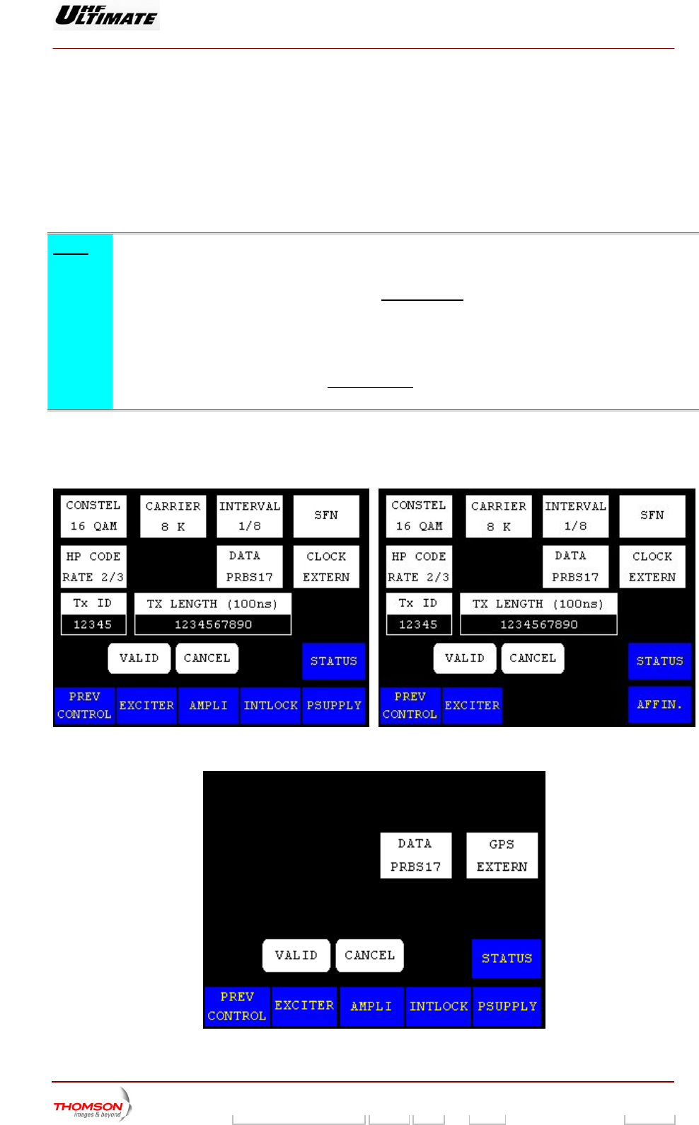
2.1.21. "COFDM or 8VSB PARAMETERS" window
card.
ow is only available with an internal COFDM modulator (DVB-T Transmitter).
This window is called up by pressing the "MODUL PARAM." control keys in the "CONTROL MAINT
Level 2" window. It is only accessible in maintenance mode.
It is used to change the COFDM or 8VSB modulator card configuration parameters stored in the CPU
The COFDM wind
Note :
♦ MODAP Version only
To set up a new pa
LUT and OLDC)
rameter configuration of the modulator, the three
should be set to the FIXED mode
corrections (ALE,
. T
US" windo
he control keys can be defined in
T Level 4" windows. the "MISCELLANEO ws and "CONTROL MAIN
♦ SIRIUS Version only
To set up a new parameter configuration of the modula two corrections (ALE, and
LUT) should be set to the FIXED mode
tor, the
. The con
"MISCELLANEOUS" window.
trol keys can be defined in the
COFDM MODULATOR
OPTIMUM FAMILY OR ULTIMATE FAMILY A FINTY FAMILY F
8VSB MODULATOR
9932 V2
45321648.01 108 B E Checked 95 / 192
Numéro / Number Doc. Rev. Lan
g
u. 27/06/2006 Pa
g
e
Digital Liquid Cooled UHF
TV Equipment
Use of commands and description of indicators
Information contained is this document is confidential, is THOMSON property and cannot be disclosed in whatever form without prior written authorization of THOMSON.
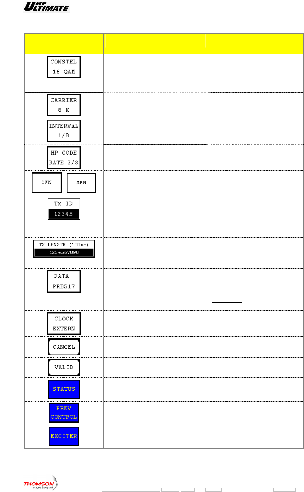
CONTROL KEYS FUNCTIONS SELECTIONS
AVAILABLE/COMMENTS
Selects the constellation type used by the
modulator.
Displays last selection.
ONSTEL 64-QAM/16-QAM /QPSK
64-QAM : 64-bit representation
16-bit representation
PSK (4-QAM) : 4-bit representation
C
16-QAM :
Q
Selects the number of transmitted carriers.
Displays last selection.
ARRIER 8K/2K C
Selects the guard interval used by the
COFDM modulator.
Displays last selection.
2; 1/16; /1/8; 1/4 INTERVAL 1/3
Selects the High Priority code rate of the
modulation.
Displays last selection.
HP CODE RATE 7/8; 5/6; 3/4; 2/3;1/2
/
Selects the network type.
Displays last selection.
SFN / MFN
Selects the transmitter ID number in an SFN
network. (*)
Displays last selection.
This value allows to address the content
of the MIP to this identified Tx.
Pressing this key calls up the
"NUMERICAL VALUE" window in which
this identification number can be
changed.
Selects the offset delay value. (*) This value can be changed by the MIP.
Pressing this key calls up the
"NUMERICAL VALUE" window in which
this time can be changed.
Selects the input signal type of the
modulator
Data PRBS 15 / Data PRBS 17 / Data
PRBS 20 / Data PRBS 23 / Data input
ASI / Data DVB_SPI (MODAP version
only)
In SFN mode, the "Data PRBS" control
keys are not validated by the system.
Selects the clock type of the exciter. CLOCK Internal / CLOCK External
In SFN mode, CLOCK external is used.
Cancels a selection.
Validates a selection.
Calls up the "STATUS" window.
Calls up the "CONTROL MAINT Level 2"
window.
Calls up the "EXCITER Level 1" window.
9932 V2
45321648.01 108 B E Checked 96 / 192
Numéro / Number Doc. Rev. Lan
g
u. 27/06/2006 Pa
g
e
Digital Liquid Cooled UHF
TV Equipment
Use of commands and description of indicators
Information contained is this document is confidential, is THOMSON property and cannot be disclosed in whatever form without prior written authorization of THOMSON.
CONTROL KEYS FUNCTIONS SELECTIONS
AVAILABLE/COMMENTS
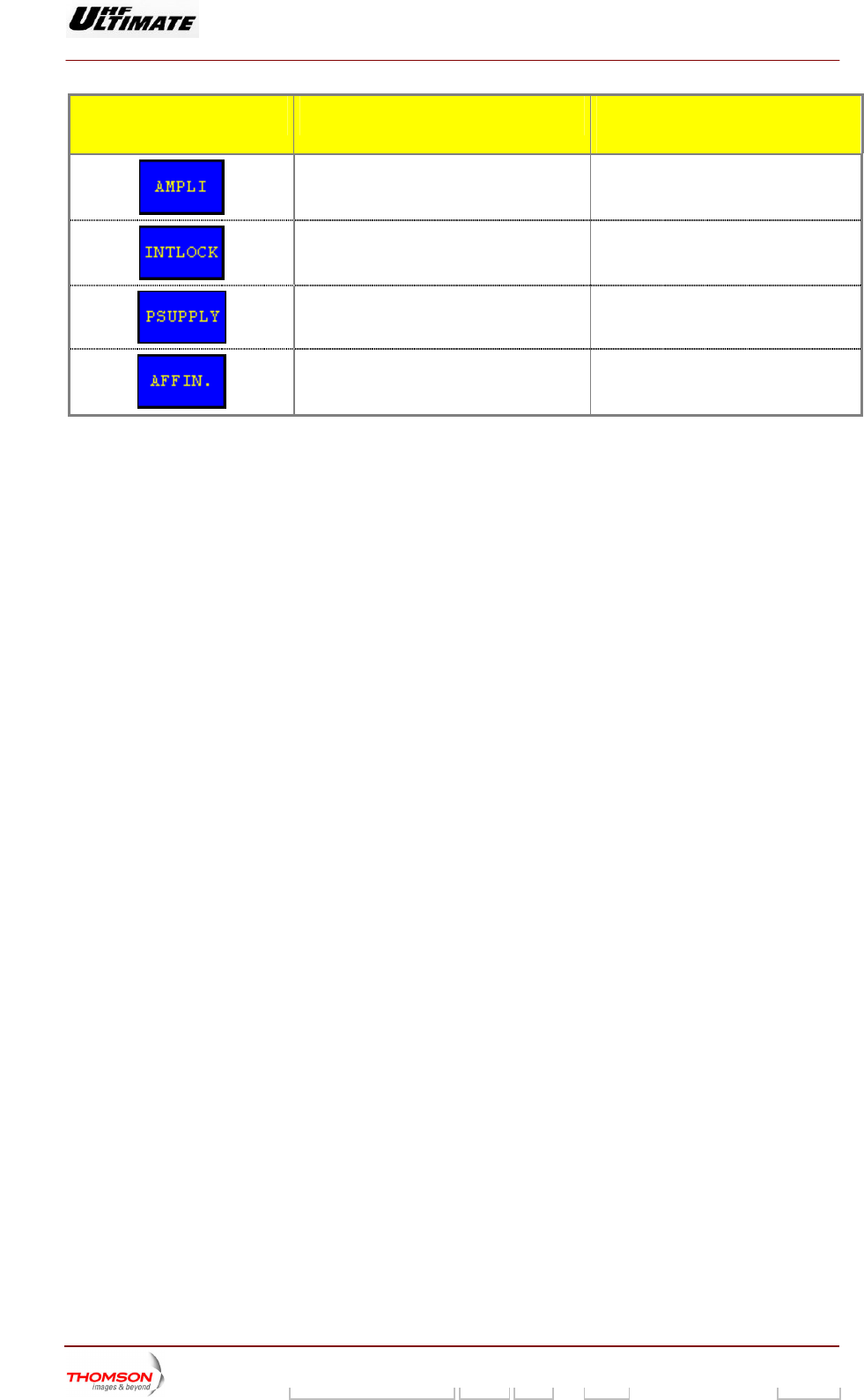
Calls up the "AMPLIFIERS" window. (a)
Calls up the «INTERLOCK» window (a)
Calls up the "POWER SUPPLY" window. (a)
Calls up the "AFFINITY" window. (b)
(*): Icon is only available in SFN mode with an internal COFDM modulator.
(a): Not Visible for AFFINITY family
(b): Not Visible for OPTIMUM or ULTIMATE families
9932 V2
45321648.01 108 B E Checked 97 / 192
Numéro / Number Doc. Rev. Lan
g
u. 27/06/2006 Pa
g
e
Digital Liquid Cooled UHF
TV Equipment
Use of commands and description of indicators
Information contained is this document is confidential, is THOMSON property and cannot be disclosed in whatever form without prior written authorization of THOMSON.
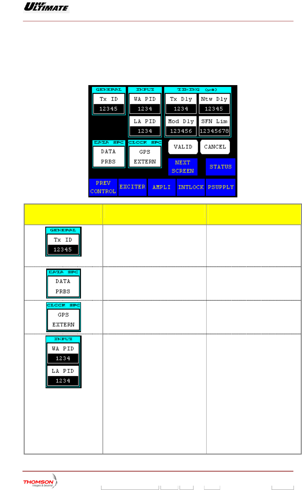
2.1.22. "FLO 1 PARAMETERS" window
This window is called up b
Level 2" window. It is only e mode.
It is used to change the Me in the CPU card.
y pressing the "MODUL PARAM." co
accessible in maintenanc
ntrol keys in the "CONTROL MAINT
diaFLO modulator card configuration parameters stored
CONTROL KEYS FUNCTIONS SELECTIONS
AVAILABLE/COMMENTS
Selects the transmitter ID number in an SF
network.
this key calls up the
N This value allows addressing the content
of the MIP to this identified Tx.
Displays last selection. Pressing
"NUMERICAL VALUE" window in which
this identification number can be
changed.
Selects the input signal type of th
modulator
e ASI / PRBS
Selects the clock type of the exciter. CLOCK Internal /
GPS Internal / GPS External
Selects the process PID number. ♦ WA PID : This value is programmed
Wid Area content process
identification (PID). If the wide area
PID value in the incoming transport
stream matches this value, the
stream is forwarded to the
channelizer as wide area content.
Otherwise, the stream is ignored.
♦ LA PID : This value is programmed
Local Area content process
identification (PID). If the local area
PID value in the incoming transport
stream matches this value, the
stream is forwarded to the
channelizer as local area content.
Otherwise, the stream is ignored.
Pressing this key calls up the
"NUMERICAL VALUE" window in which
this PID number can be changed.
9932 V2
45321648.01 108 B E Checked 98 / 192
Numéro / Number Doc. Rev. Lan
g
u. 27/06/2006 Pa
g
e
Digital Liquid Cooled UHF
TV Equipment
Use of commands and description of indicators
Information contained is this document is confidential, is THOMSON property and cannot be disclosed in whatever form without prior written authorization of THOMSON.
CONTROL KEYS FUNCTIONS SELECTIONS
AVAILABLE/COMMENTS
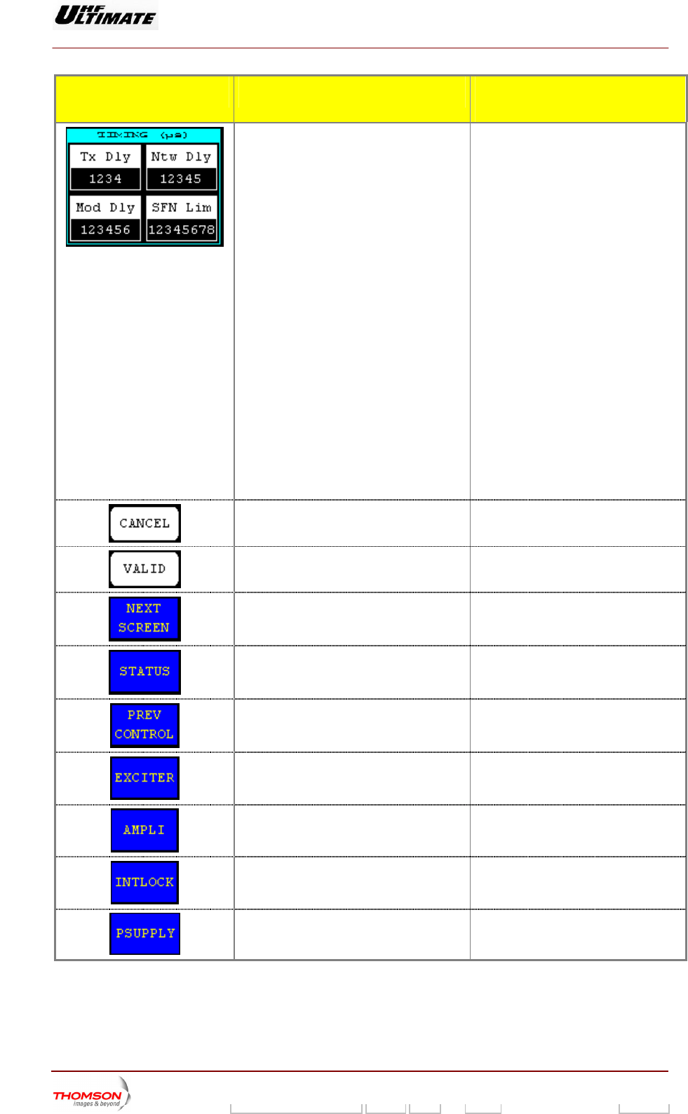
Selects the delay value. ♦ Mod Dly : The number of clock
cycles corresponding to the delay
through the FLO modulator core.
This is set to align the start of
superframe at the RF output to the
GPS 1PPS.
♦ TX Dly : This value is the latency
associated with the transmit
hardware. It’s used to compensate
for the transmit delay in order to
synchronize transmissions from
multiple sites in an SFN network.
♦ Ntw Dly: This value is the latency
associated with the geographic
separation of transmitters. It’s used
to synchronize transmissions from
multiple sites in an SFN network.
♦ SFN lim: If the absolute value of the
system clock integrity count is
greater than this limit, it is out of
range and an alarm generated.
Pressing this key calls up the
"NUMERICAL VALUE" window in which
this value can be changed.
Cancels a selection.
Validates a selection.
Calls up the "FLO 2 MODULATOR
PARAMETERS" window.
Calls up the "STATUS" window.
Calls up the "CONTROL MAINT Level 2"
window.
Calls up the "EXCITER Level 1" window.
Calls up the "AMPLIFIERS" window.
Calls up the «INTERLOCK» window
Calls up the "POWER SUPPLY" window.
9932 V2
45321648.01 108 B E Checked 99 / 192
Numéro / Number Doc. Rev. Lan
g
u. 27/06/2006 Pa
g
e
Digital Liquid Cooled UHF
TV Equipment
Use of commands and description of indicators
Information contained is this document is confidential, is THOMSON property and cannot be disclosed in whatever form without prior written authorization of THOMSON.
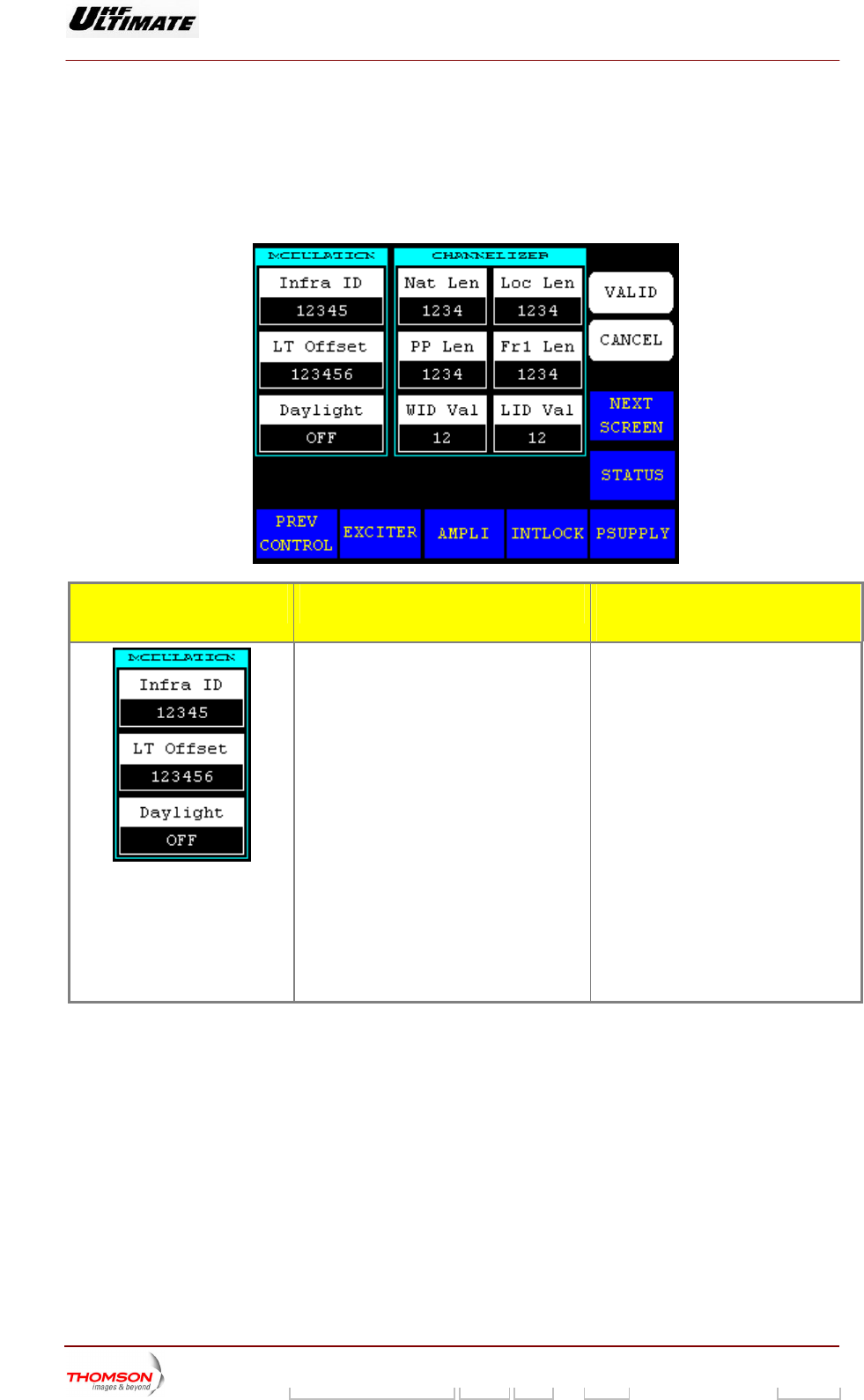
2.1.23. "FLO 2 PARAMETERS" window
TERS" window. It is only accessible in maintenance mode.
This window is called up by pressing the "NEXT SCREEN." control keys in the "FLO 1 MODULATOR
PARAME
It is used to change the MediaFLO modulator card configuration parameters stored in the CPU card.
CONTROL KEYS FUNCTIONS SELECTIONS
AVAILABLE/COMMENTS
Selects values of the modulation
parameters.
♦ Infra ID: This value is in
the infrastructure ID
serted into
field of the Local
cal time offset field of the local
key calls up the
r can be changed.
is inserted into the
daylight field of the local system
parameters message.
system parameters message. The
network sets this field to the identifier
assigned to the local area
infrastructure.
♦ LT Offset: This value is inserted into
the lo
system parameters message.
Pressing this
"NUMERICAL VALUE" window in which
this PID numbe
♦ Daylight: ON / OFF
This indicator
ON: Local transmitter time is daylight
saving time.
9932 V2
45321648.01 108 B E Checked 100 / 192
Numéro / Number Doc. Rev. Lan
g
u. 27/06/2006 Pa
g
e
Digital Liquid Cooled UHF
TV Equipment
Use of commands and description of indicators
Information contained is this document is confidential, is THOMSON property and cannot be disclosed in whatever form without prior written authorization of THOMSON.
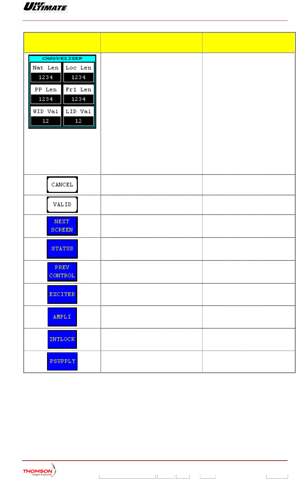
CONTROL KEYS FUNCTIONS SELECTIONS
AVAILABLE/COMMENTS
Selects values of the channelizer
parameters.
♦ Nat Len: Exciter initialization register
indicates National Length.
♦ Loc Len: Exciter initialization register
indicates Local Length.
♦ PP Len: Exciter initialization register
indicates Positioning Pilot Length.
♦ F register
indicates FrameLength.
♦ WID Val: Exciter initialization register
indicates WID scrambler sequence
number.
♦ LID Val: Exciter initialization register
indicates LID scrambler sequence
number
Pressing this key calls up the
"NUMERICAL VALUE" window in which
this value can be changed.
r1 Len: Exciter initialization
Cancels a selection.
Validates a selection.
Calls up the "CONTROL MAINT Level 2"
window.
Calls up the "STATUS" window.
Calls up the "FLO 1 MODULATOR
PARAMETERS" window.
Calls up the "EXCITER Level 1" window.
Calls up the "AMPLIFIERS" window.
Calls up the «INTERLOCK» window
Calls up the "POWER SUPPLY" window.
9932 V2
45321648.01 108 B E Checked 101 / 192
Numéro / Number Doc. Rev. Lan
g
u. 27/06/2006 Pa
g
e
Digital Liquid Cooled UHF
TV Equipment
Use of commands and description of indicators
Information contained is this document is confidential, is THOMSON property and cannot be disclosed in whatever form without prior written authorization of THOMSON.
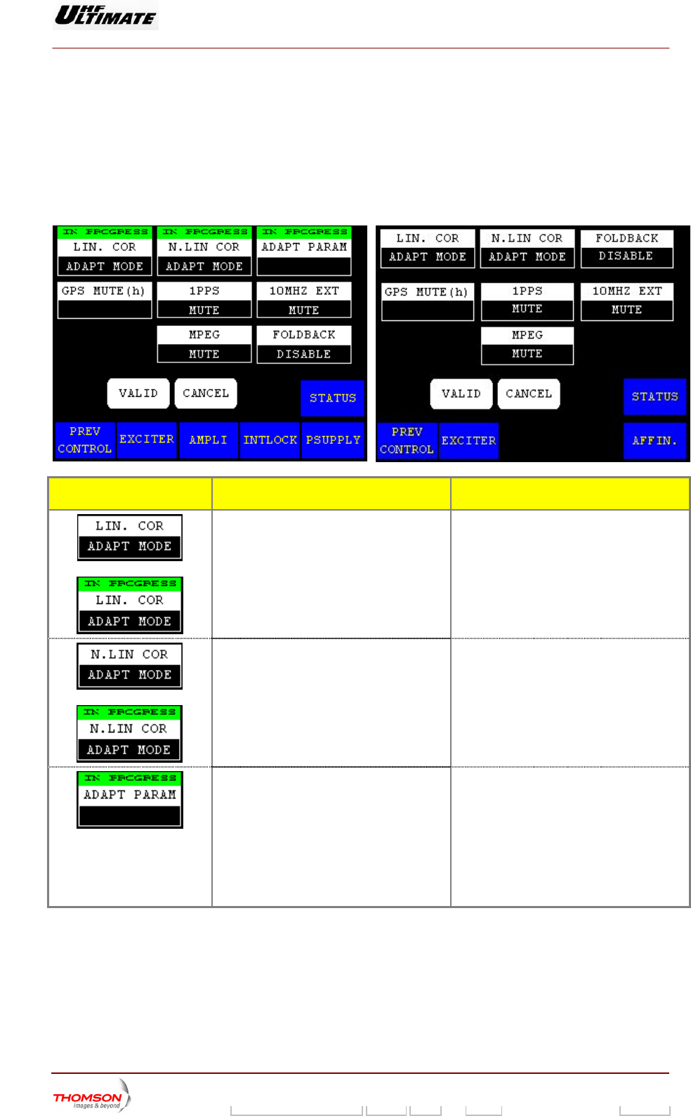
2.1.24. "MISCELLANEOUS" window
ow is called up by This wind pressing the "MISC PARAM." control keys in the "CONTROL MAINT
Level 2" window. It is only accessible in maintenance mode.
It is used to change the ADAPT exciter operation configuration parameters stored in the CPU card.
OPTIMUM FAMILY OR ULTIMATE FAMILY AFFINTY FAMILY
CONTROL KEYS FUNCTIONS DISPLAY/COMMENTS
Toggles between fixed and adaptive
correction of signal
Displays last selection.
LIN. COR ADAPT MODE / LIN. COR FIXED
MODE
The text colour of control key is grey when
you select the a aptive mode.
L is
OR
distortion.
d
Command is disabled while the PC
locked (disabled).
OR
Displays the current operating mode of the
LUT.
Displays last selection.
N. LIN COR ADAPT MODE / N.LIN COR
FIXED MODE
The text colour of control key is grey when
you select the adaptive mode.
Command is disabled while the PCL is
locked (disabled).
Selects the coefficients of the corrections for
antenna exciter.
SAVE / RECALL
Press this control key and validation
♦ SAVEL: Allows saving coefficients into
tables of corrections.
♦ REC tions by
using corded.
ALL: Allows loading correc
coefficients beforehand re
Recalls the coefficients of the last save.
9932 V2
45321648.01 108 B E Checked 102 / 192
Numéro / Number Doc. Rev. Lan
g
u. 27/06/2006 Pa
g
e
Digital Liquid Cooled UHF
TV Equipment
Use of commands and description of indicators
Information contained is this document is confidential, is THOMSON property and cannot be disclosed in whatever form without prior written authorization of THOMSON.
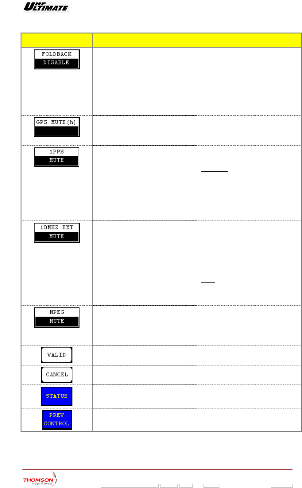
CONTROL KEYS FUNCTIONS DISPLAY/COMMENTS
Selects the reflected (reserve) power control
mode.
Control key available according to your
installation mode
FOLDBACK ENABLED: When the reflected
ower value is higher than the threshold
lue (3%) the power control is progressively
roduce through an algorithm.
FOLDBACK DISABLED: When the reflected
power value is higher than the threshold
) the power control is produce by
airway (-3dB, -6dB and halt ‘no power”)
p
va
p
value (3%
st
Displays the actual time during which the
transmitter has been in operation since the
GPS was muted (Absent). (1)
ange of variation: From 0 to 99 hours
In case of the value of display is 0 hour, the
transmitter is still working (not mute).
Displays last selection.
R
Selects the 1PPS changeover mode.
Displays last selection.
OT MUTE
Icon is available in SFN mode only.
NOT MUTE
MUTE / N
: In case of disable of 1 PPS
gnal the transmitter is still working. The
work is disturbs
si
SFN net
MUTE: In case of disable of 1 PPS signal the
transmitter is stopped.
When the 1 PPS signal reappear with
10MHz signal present the transmitter start
alone.
Selects the 10MHz EXT changeover mode.
Displays last selection.
MUTE / NOT MUTE
Icon is available in SFN mode only.
Visible for External GPS only, Control key
sed: CLK SOURCE
NOT MUTE
u
: In case of disable of 10Mhz
itter is still working. The
sturbs
signal the transm
SFN network is di
MUTE: In case of dis
the transmitter is stopped
able of 10MHz signal
.
PPS When the 10Mhz signal reappear with 1
signal present the transmitter start alone.
S
(1)
elects the input signal changeover mode.
PRBS
Displays last selection.
MUTE /
SFN mode: this control key has no effect.
The icon is only available in MFN mode
MFN mode: this control key is used to select
the input signal switching m
ode.
Validates a selection.
Cancels a selection.
Calls up the "TRANSMITTER STATUS"
window.
Calls up the "CONTROL MAINT Level 3"
window.
9932 V2
45321648.01 108 B E Checked 103 / 192
Numéro / Number Doc. Rev. Lan
g
u. 27/06/2006 Pa
g
e
Digital Liquid Cooled UHF
TV Equipment
Use of commands and description of indicators
Information contained is this document is confidential, is THOMSON property and cannot be disclosed in whatever form without prior written authorization of THOMSON.
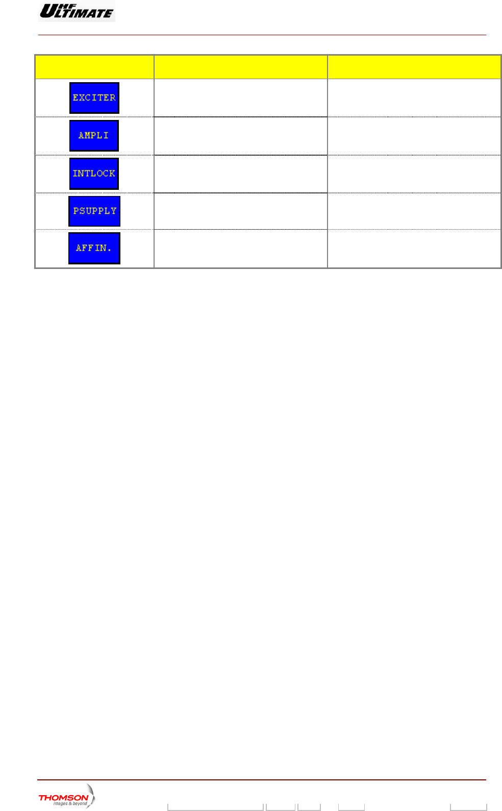
CONTROL KEYS FUNCTIONS DISPLAY/COMMENTS
Calls up the "EXCITER Level 1" window.
Calls up the "AMPLIFIERS" window. (a)
Calls up the «INTERLOCK» window (a)
Calls up the "POWER SUPPLY" window. (a)
Calls up the "AFFINITY" window. (b)
(a): Not Visible for AFFINITY family
(b): Not Visi ULTIMATE families
(1): Not Visible for MediaFLO modulator
ble for OPTIMUM or
9932 V2
45321648.01 108 B E Checked 104 / 192
Numéro / Number Doc. Rev. Lan
g
u. 27/06/2006 Pa
g
e
Digital Liquid Cooled UHF
TV Equipment
Use of commands and description of indicators
Information contained is this document is confidential, is THOMSON property and cannot be disclosed in whatever form without prior written authorization of THOMSON.
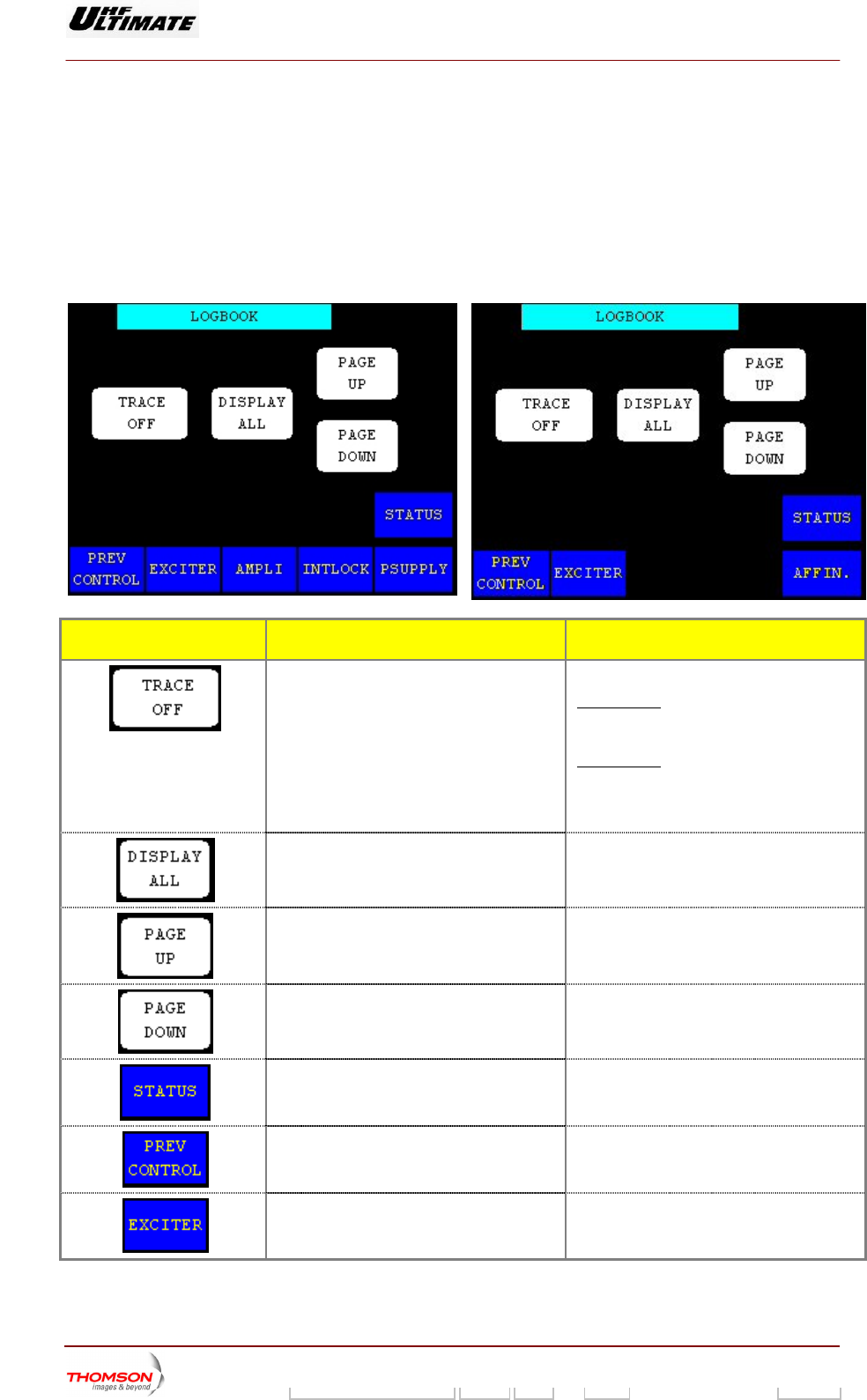
2.1.25. "LOGBOOK" window
This window called up b ys in the "
window.
It controls the downloading of the log book data to a terminal. This
transmitter is in maintenance mode.
OPTIMUM FAMILY OR ULTIMATE FAMILY
is y pressing the "LOGBOOK" control ke CONTROL MAINT Level 2"
window is only accessible when the
AFFINTY FAMILY
CONTROL KEYS FUNCTIONS DISPLAY/COMMENTS
Selects the type of information flow to the log
book terminal.
Displays the type of information flow
selected.
TRACE OFF / TRACE ON
TRACE ON : the log book output
continuous, data regarding each even
is
t is
sent in a real time to the logbook terminal.
TRACE OFF : the three other buttons are
operational.
Command is disabled while the PCL is
locked (disabled).
Displays all events stored in the log book. Command is disabled while the PCL is
locked (disabled).
Displays the 20 events ahead of the last
events accessed by the operator.
Command is disabled while the PCL is
locked (disabled).
Displays the 20 events which follow on from
the last events accessed by the operator.
Command is disabled while the PCL is
locked (disabled).
Calls up the "TRANSMITTER STATUS"
window.
Calls up the "CONTROL Level 2" window.
Calls up the "EXCITER Level 1" window.
9932 V2
45321648.01 108 B E Checked 105 / 192
Numéro / Number Doc. Rev. Lan
g
u. 27/06/2006 Pa
g
e
Digital Liquid Cooled UHF
TV Equipment
Use of commands and description of indicators
Information contained is this document is confidential, is THOMSON property and cannot be disclosed in whatever form without prior written authorization of THOMSON.
CONTROL KEYS FUNCTIONS DISPLAY/COMMENTS
Calls up the "AMPLIFIERS" window. (a)
Calls up the «INTERLOCK» window (a)
Calls up the "POWER SUPPLY" window. (a)
Calls up the "AFFINITY" window. (b)
(a): Not Visible for AFFINITY family
(b): Not Visible for OPTIMUM or ULTIMATE families
INDICATOR LAMPS AND
MESSAGE DISPLAYS
FUNCTIONS DISPLAY/COMMENTS
Gives the window name.
9932 V2
45321648.01 108 B E Checked 106 / 192
Numéro / Number Doc. Rev. Lan
g
u. 27/06/2006 Pa
g
e
Digital Liquid Cooled UHF
TV Equipment
Use of commands and description of indicators
Information contained is this document is confidential, is THOMSON property and cannot be disclosed in whatever form without prior written authorization of THOMSON.
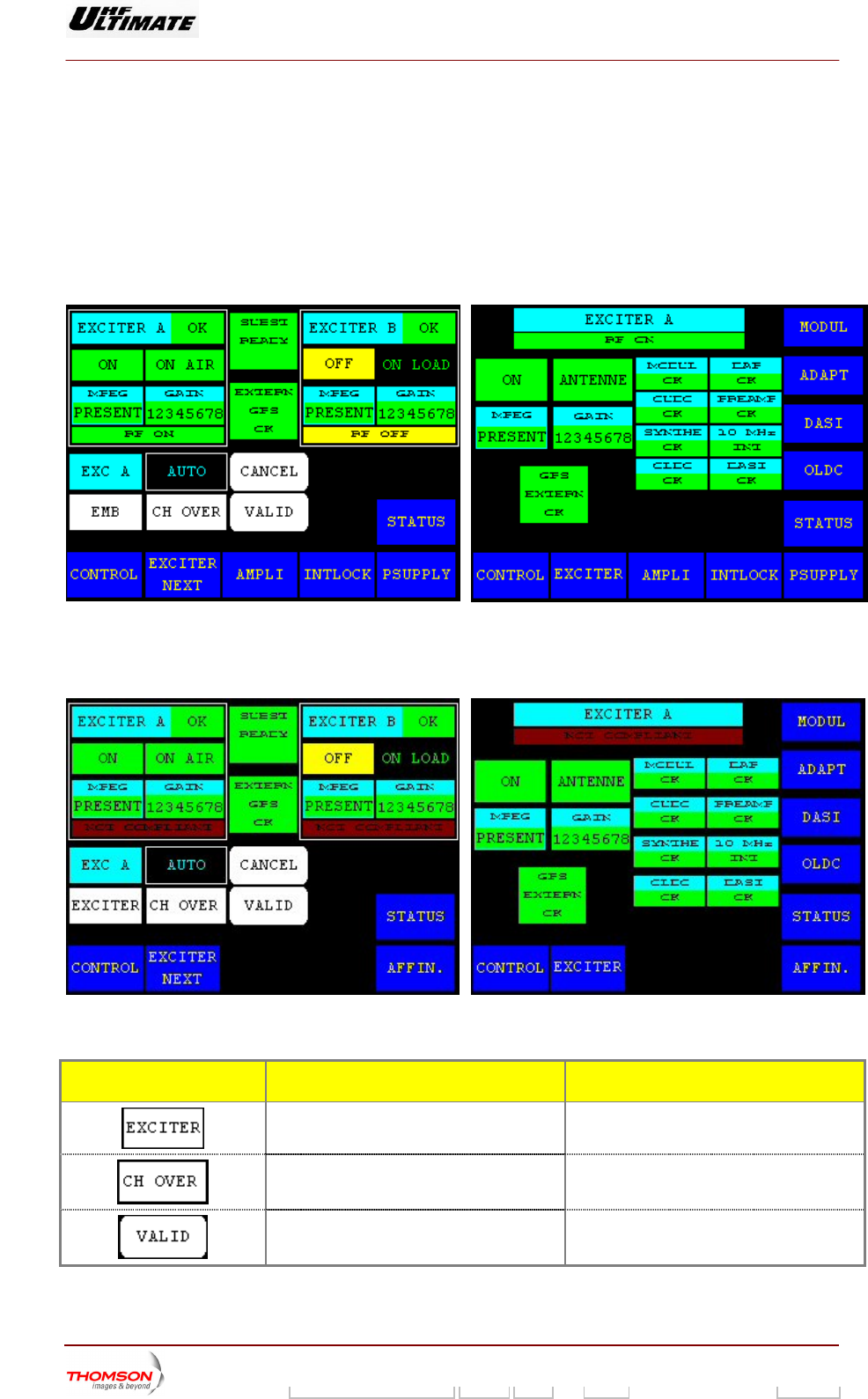
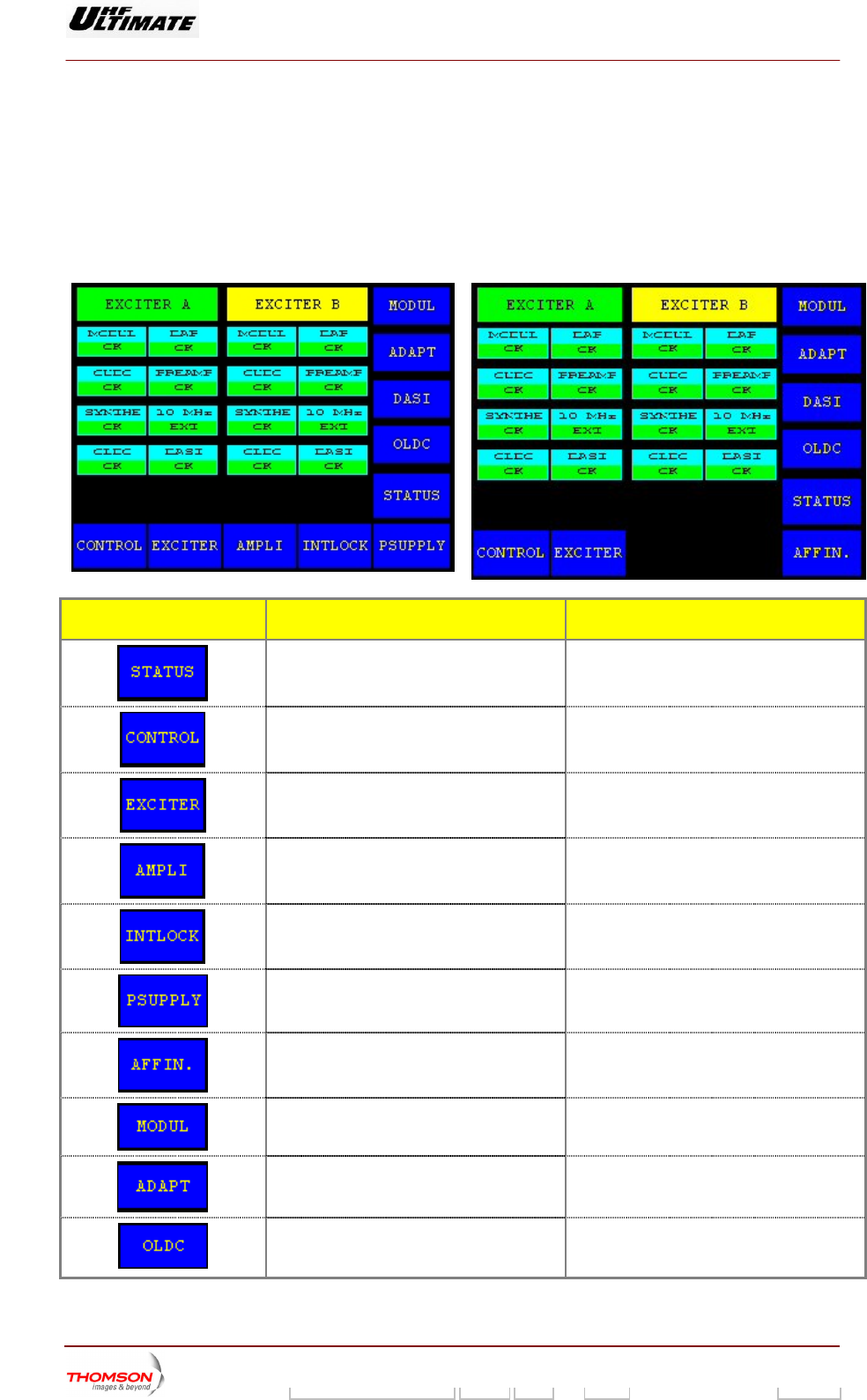
2.1.26. "EXCITER Level 1" window, or "EXCITER PANEL" window, MODAP version
ONLY
From other windows it can
This window, which is calle in an SD transm
cards. It also provides for selecting an exciter and configuring the for the exciters *.
UM FAMILY OR ULTIMATE FAMILY
be called up by pressing the "EXCITE
d "EXCITER PANEL"
R" key.
itter, displays the status of the exciter
changeover mode
OPTIM
Figure 24 : Dual Drive Transmitter Figure
AFFINTY FAMILY
25 : Single Drive Transmitter
Figure 26 : Dual Drive Transmitter Figure 27 : Single Drive Transmitter
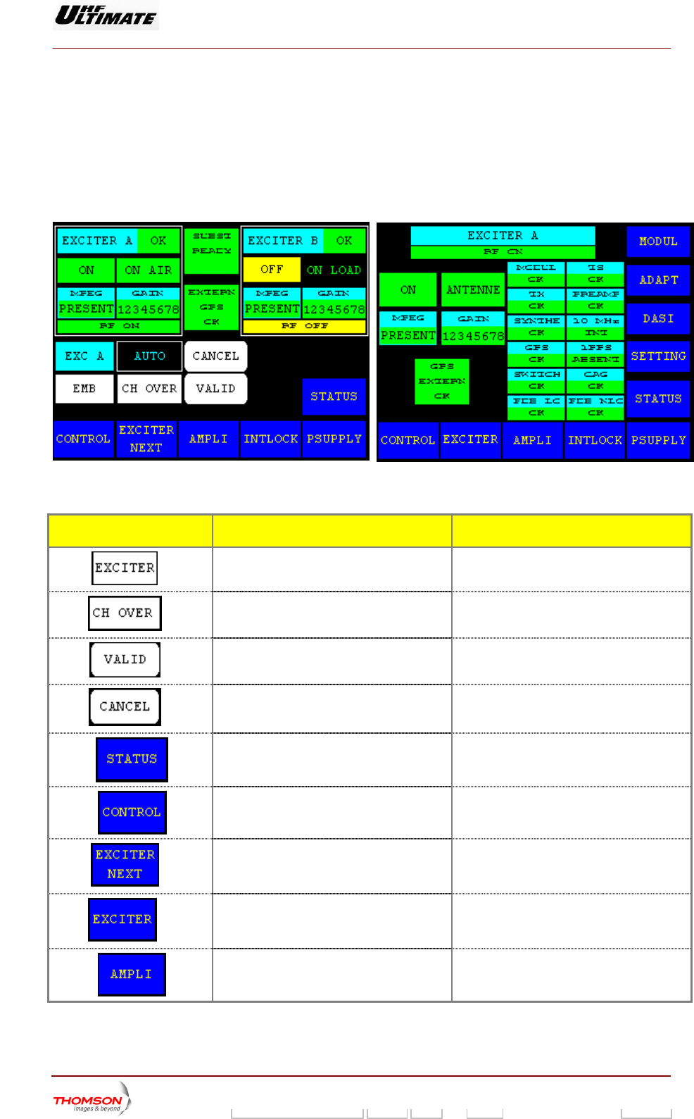
CONTROL KEYS FUNCTIONS DISPLAY/COMMENTS
Selects the exciter to be connected to the
amplifier channel (exciter to antenna). (*)
Command is disabled while the PCL is
locked (disabled).
Selects the exciter changeover mode
(Automatic or Manual). (*)
Command is disabled while the PCL is
locked (disabled).
Validates a selection. (*)
9932 V2
45321648.01 108 B E Checked 107 / 192
Numéro / Number Doc. Rev. Lan
g
u. 27/06/2006 Pa
g
e
Digital Liquid Cooled UHF
TV Equipment
Use of commands and description of indicators
Information contained is this document is confidential, is THOMSON property and cannot be disclosed in whatever form without prior written authorization of THOMSON.
CONTROL KEYS FUNCTIONS DISPLAY/COMMENTS
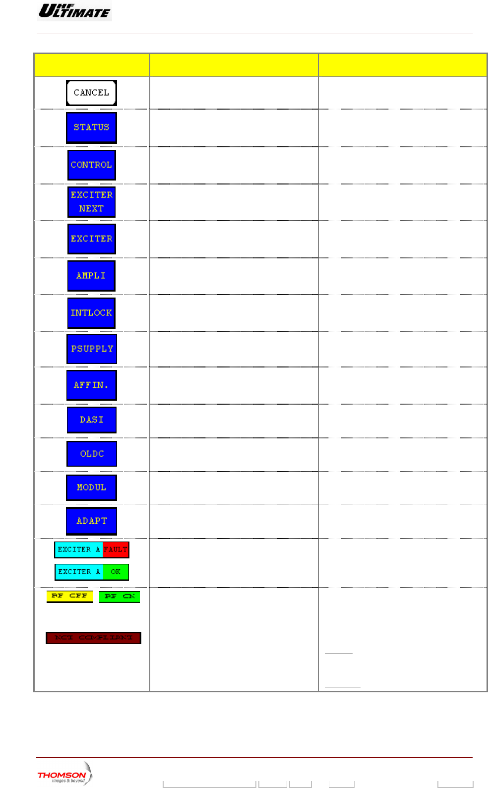
Cancels a selection. (*)
window.
Calls up the "TRANSMITTER STATUS"
Calls up the "CONTROL Level 1" window.
Calls up the "EXCITER Level 2" window. (*)
Calls up the "EXCITER PANEL" window. (**)
Calls up the "AMPLIFIERS" window. (a)
Calls up the «INTERLOCK» window (a)
w. (a) Calls up the "POWER SUPPLY" windo
Calls up the "A . (b) FFINITY" window
Calls up the "DASI STATUS" window (**) This control keys is available and visible in
case of DASI board is fitted according with
your installation choice
Calls up the "OLDC STATUS" window. (**) his control keys is available and visible in
se of OLDC board is fitted according with
ur installation choice
T
ca
yo
Calls up the "MODULATOR " window, in
case of a DVB-T Transmitter. (**)
This control keys is not used in case of an
ATSC Transmitter.
Calls up the " ADAPT PARAMETERS "
window. (**)
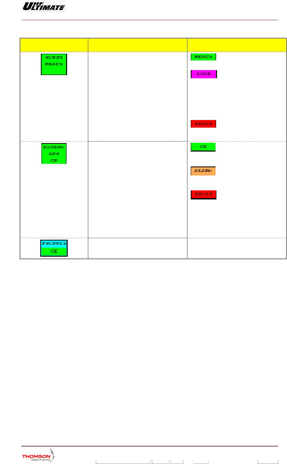
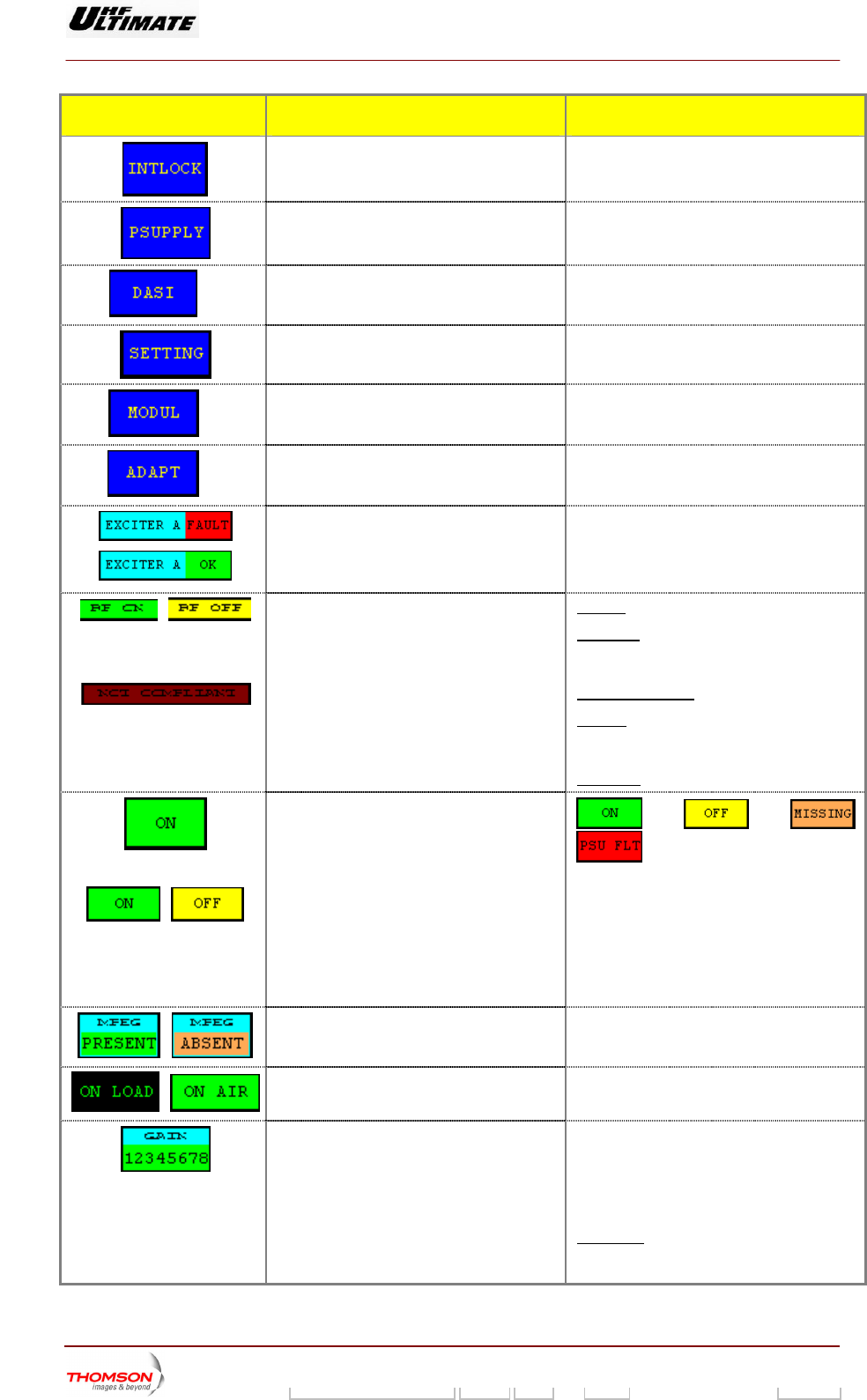
Indicates the exciter status (proper operation EXCITER A OK /
B OK
ULT /
XCITER. B FAULT (1)
or fault). EXCITER
EXCITER. A FA
E
Indicates whether the exciter delivered the
RF power to a load, or on-air.
software configuration and that of the
MODAP.
RF ON: RF signal on the exciter output.
F OFF: RF signal absence on the exciter
utput.
OT COMPLIANT
Flashes
/
O
Indicates the consistency between the CPU
R
o
N
r
if the CPU software configuration is
not consistent with that of the MODAP. Red
quare is blinking of light. s
Otherwise not visible.
9932 V2
45321648.01 108 B E Checked 108 / 192
Numéro / Number Doc. Rev. Lan
g
u. 27/06/2006 Pa
g
e
Digital Liquid Cooled UHF
TV Equipment
Use of commands and description of indicators
Information contained is this document is confidential, is THOMSON property and cannot be disclosed in whatever form without prior written authorization of THOMSON.
CONTROL KEYS FUNCTIONS DISPLAY/COMMENTS
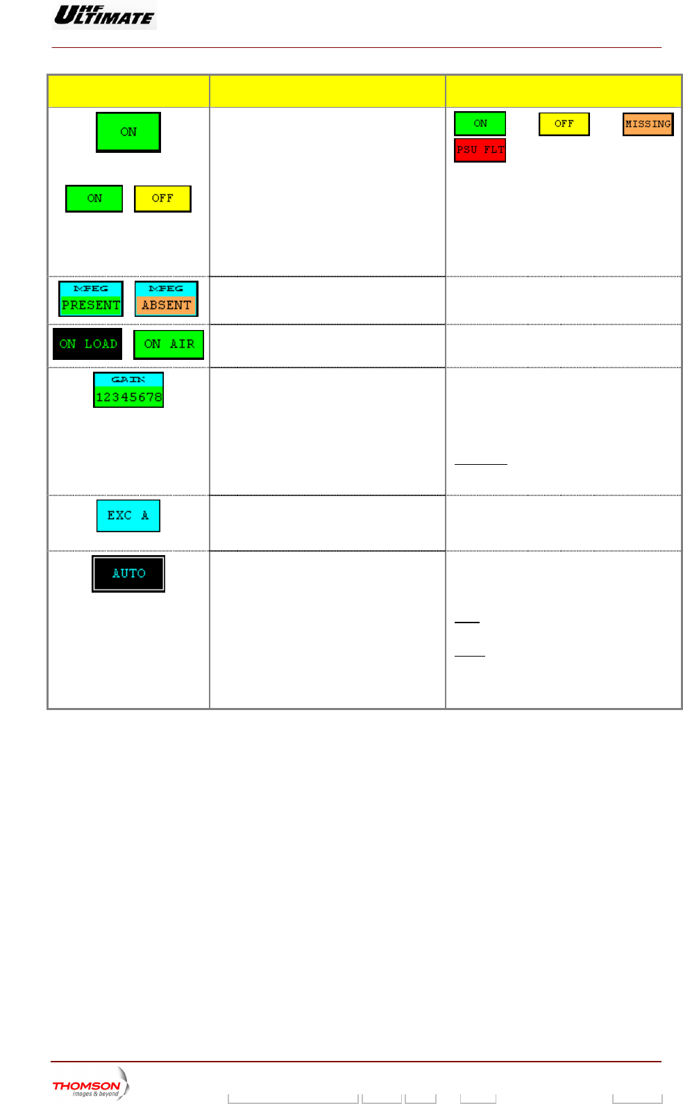
Indicates the overall status of the exciter.
, , ,
Exciter "ON" status is displayed in green.
ed in yellow
AP Power supply is faulty,
n red.
issing, the status is
Exciter "" status is display
PSU FLT : MOD
the status is displayed i
MISSING : DAP card is m
displayed in red.
/
Indicates presence or absence of an MPEG2
. input signal on the relevant exciter
MPEG PRESENT / MPEG MISSING (1)
/
/
Indicates whether the exciter is connected to
a load, or on-air.
ON LOAD / ON AIR
Indicates the current transmission power
level.
and -6 dB and the
HALT indication are displayed in reverse
video.
PWR= 0 dB / PWR= -3dB / PWR= -6 dB /
PWR= STOPPED
Exciter levels of -3 dB
STOPPED : The transmitter is switched off-
ers.
air when there is an SWR fault or
OVERDRIVE fault on the power amplifi
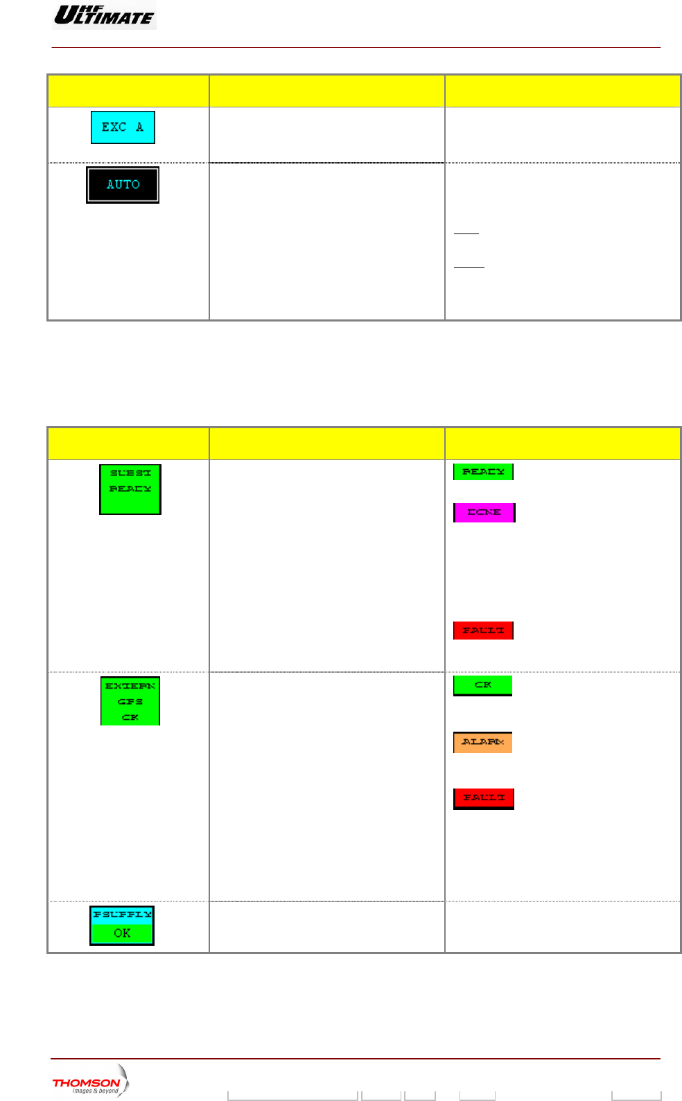
Indicates the exciter selected. (*) EXC A / EXC B
Flashes until the "EXCITER SEL" command
is either validated or cleared.
Flashes until the "CH OVER" command is
either validated or cleared.
Indicates the exciter changeover mode. (*) MAN / AUTO
MAN (Manual) : only
command.
when operator gives a
AUTO : when the selected exciter is faulty.
A manual changeover can be commanded
regardless of which changeover mode has
been selected.
(*) : Only in Double Drive Version
(**) : Single Drive Version
(1) : A fault-free status is displayed in normal video (on black in
case of colo actile scree layed in reve ckground or on
red background in case of colour tactile screen).
(a): Not Visible for AFFINITY family
(b): Not Visible for OPTIMUM or ULTIMATE families
background or green background
ur t n). A faulty status is disp rse video (on white ba
9932 V2
45321648.01 108 B E Checked 109 / 192
Numéro / Number Doc. Rev. Lan
g
u. 27/06/2006 Pa
g
e
Digital Liquid Cooled UHF
TV Equipment
Use of commands and description of indicators
Information contained is this document is confidential, is THOMSON property and cannot be disclosed in whatever form without prior written authorization of THOMSON.
MESSAGES FUNCTIONS DISPLAY/COMMENTS
Indicates the exciter changeover status in
automatic mode. : the changeover system is
ready for an automatic switch over.
: the changeover system is no
longer available and it is necessary to
eir consequences; similarly
for all selections carried out on the PCL).
change the exciter selected or to carry out a
transmitter "RESET" (in this latter case, care
must be taken because fault data for all
faults which have disappeared will be erased
together with th
: an attempt to carry out an
automatic changeover has failed and the
buzzer will be triggered.
Indicates the external GPS changeover
status. : the changeover system is
ready for an automatic switch over. The free
contact o . f the external GPS is closed
: the changeover system is no
longer available. The free contact of the
external GPS is openned.
: an attempt to carry out an
automatic changeover has failed. The free
contact of the external GPS is openned
In case of disable GPS signal the transmitter
is stopped after a delay time according to
"GPS MUTE (h) " control key in the
"MISCELLANEOUS" window.
Indicates the status of the very low voltage
power supply of the exciter. (2)
P. SUPPLY OK / P. SUPPLY FAULT (1)
(1) A fault-free status ackgroun
in case of colour tac en). A faulty status is displayed
background or on red background in case of colour tactile s
(2) Only Single Drive version.
is displayed in normal video (on black b
tile scre
d or on green background
in reverse video (on white
creen).
9932 V2
45321648.01 108 B E Checked 110 / 192
Numéro / Number Doc. Rev. Lan
g
u. 27/06/2006 Pa
g
e
Digital Liquid Cooled UHF
TV Equipment
Use of commands and description of indicators
Information contained is this document is confidential, is THOMSON property and cannot be disclosed in whatever form without prior written authorization of THOMSON.
2.1.27. "EXCITER Level 2" window, MODAP version ONLY
This window is called up by pressing the "EXCITER NEXT" control keys in the "EXCITER Level 1"
window.
It displays the status of the exciter signals. This window is only available in Double Drive Transmitters.
OPTIMUM FAMILY OR ULTIMATE FAMILY
AFFINTY FAMILY
CONTROL KEYS FUNCTIONS DISPLAY/COMMENTS
Calls up the "TRANSMITTER STATUS"
window.
Calls up the "CONTROL Level 1" window.
Calls up the "EXCITER Level 1" window.
Calls up the "AMPLIFIERS" window. (a
)
Calls up the «INTERLOCK» window (a)
Calls up the "POWER SUPPLY" window. (a)
Calls up the "AFFINITY" window. (b
)
Calls up the "MODULATOR " window, in
case of a DVB-T Transmitter
This control keys is not used in case of an
ATSC Transmitter.
Calls up the " ADAPT PARAMETERS "
window.
Calls up the "OLDC STATUS" window. This control keys is available and visible in
case of OLDC board is fitted according with
your installation choice
9932 V2
45321648.01 108 B E Checked 111 / 192
Numéro / Number Doc. Rev. Lan
g
u. 27/06/2006 Pa
g
e
Digital Liquid Cooled UHF
TV Equipment
Use of commands and description of indicators
Information contained is this document is confidential, is THOMSON property and cannot be disclosed in whatever form without prior written authorization of THOMSON.
CONTROL KEYS FUNCTIONS DISPLAY/COMMENTS
Calls up the "DASI STATUS" window This control keys is available and visible in
case of DASI board is fitted according with
your installation choice
(a): Not Visible for AF NIT
(b): Not Visible for OPTIMUM or ULTIMATE families
FI Y family
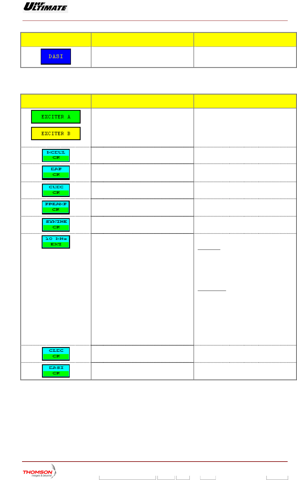
MESSAGE FUNCTIONS DISPLAY/COMMENTS
Shows the double column of the relevant
exciters (1).
EXCITER A / EXCITER B
round:
ground:
Exciter non selected
exciter. (*)
Indicates which exciter is selected and which
is on-air, as well as the status (fault-free or
faulty) of both
Message is displayed on green backg
Exciter selected
Message is displayed on yellow back
Indicates the overall status of the COFDM
modulator.
MODULAT OK / MODULAT FAULT (
1)
Indicates the overall status of the DAP. DAP OK / DAP FAULT (1)
Indicates the overall status of the CUDC. AULT (1) CUDC OK / CUDC F
Indicates the overall status of the
preamplifier.
PREAMP OK / PREAMP FAULT (1)
Indicates the overall status of the RF
synthesiser.
SYNTHE OK / SYNTHE FAULT (1)
Indicates the status of the 10 MHz drive
oscillator. Fir
10 MHz EXT / 10 MHz INT
st case: "10 MHz INT" control keys in
"INSTALLATION PARAMETERS Level 1"
wi dow is selected.
A status messa
n
♦ ge (10 MHz ext or 10 MHz
INT) is displayed in normal video (on
black background).
Second case: "10 MHz EXT" control keys in
♦
n black
♦
se video (on white
"INSTALLATION PARAMETERS Level 1"
window is selected.
A status message (10 MHz EXT) is
displayed in normal video (o
background).
A fault message (10 MHz INT) is
displayed in rever
background).
Indicates the overall status of the OLDC unit. OLDC OK / OLDC FAULT (1)
Indicates the overall status of the DASI
board.
DASI OK / DASI FAULT (1)
(1) A fault free status is displayed in normal video (on black ba
case of colour tactile screen). A faulty status is displayed in
or on red background in case of colour tactile screen).
ckground or on green background in
reverse video (on white background
9932 V2
45321648.01 108 B E Checked 112 / 192
Numéro / Number Doc. Rev. Lan
g
u. 27/06/2006 Pa
g
e
Digital Liquid Cooled UHF
TV Equipment
Use of commands and description of indicators
Information contained is this document is confidential, is THOMSON property and cannot be disclosed in whatever form without prior written authorization of THOMSON.
2.1.28. "EXCITER Level 1" window, or "EXCITER PANEL" window, SIRIUS version
ONLY
From other windows it can be called up by pressing the "EXCITE
This window, which is called "EXCITER PANEL" in an SD transm e exciter
cards. It also provides for selecting an exciter and configuring the r the exciters *.
R" key.
itter, displays the status of th
changeover mode fo
Figure 28 : Dual Drive Transmitter Figure 29 : Single Drive Transmitter
CONTROL KEYS FUNCTIONS DISPLAY/COMMENTS
(*)
Selects the exciter to be connected to the
amplifier channel (exciter to antenna).
Command is disabled while the PCL is
locked (disabled).
(*)
Selects the exciter changeover mode
(Automatic or Manual).
Command is disabled while the PCL is
locked (disabled).
(*)
Validates a selection.
(*)
Cancels a selection.
Calls up the "TRANSMITTER STATUS"
window.
Calls up the "CONTROL Level 1" window.
(*)
Calls up the "EXCITER Level 2" window.
(**)
Calls up the "EXCITER PANEL" window.
Calls up the "AMPLIFIERS" window.
9932 V2
45321648.01 108 B E Checked 113 / 192
Numéro / Number Doc. Rev. Lan
g
u. 27/06/2006 Pa
g
e
Digital Liquid Cooled UHF
TV Equipment
Use of commands and description of indicators
Information contained is this document is confidential, is THOMSON property and cannot be disclosed in whatever form without prior written authorization of THOMSON.
CONTROL KEYS FUNCTIONS DISPLAY/COMMENTS
Calls up the «INTERLOCK
» window
Calls up the "POWER SUPPLY" window.
(**)
Calls up the "DASI STATUS" window This control keys is available and visible in
case of DASI b ith
your ins
oard is fitted according w
tallation choice
Calls up the "SETTING" window
(**)
Call
cas mitter ATS
s up the "MODULATOR " window, in
e of a DVB-T Trans
This control keys is not used in case of an
C Transmitter.
(**)
Calls up the " ADAPT PARAMETERS "
window.
Indicates the exciter status (proper operation
or fa
EXCITER A OK /
XC
EXC
EXCITER. B FA
ult). E ITER B OK
ITER. A FAULT /
ULT (1)
Indicates whether the exciter delivered RF
power to a load or on-air.
Indicates the consistency between the CPU
software configuration and that of the
SIRIUS exciter.
RF ON: RF signal on the exciter output
F: RF OF RF signal absence on the exciter
OMPLIANT
output
NOT C
Flashes if the CPU software configuration is
t c nsistent with that of the SIRIUS
. Red square is blinking of light.
ise
no o
exciter
Otherw not visible.
/
Or
/
Indicates the overall status of the exciter.
, , ,
Exciter "ON" status is displayed in green.
Exciter "" status is displayed in yellow
PSU FLT : Exciter Power supply is faulty, the
status is displayed in red.
MISSING : DIGITAL card is missing, the
status is displayed in orange.
/
Indicates presence or absence of an MPEG2
input signal on the relevant exciter.
MPEG PRESENT / MPEG MISSING (1)
/
Indicates whether the exciter is connected to
a load, or on-air.
ON LOAD / ON AIR
Indicates the current transmission power
level.
PWR= 0 dB / PWR= -3dB / PWR= -6 dB /
PWR= STOPPED
Exciter levels of -3 dB and -6 dB and the
HALT indication are displayed in reverse
video.
STOPPED : The transmitter is switched off-
air when there is an SWR fault or
OVERDRIVE fault on the power amplifiers.
9932 V2
45321648.01 108 B E Checked 114 / 192
Numéro / Number Doc. Rev. Lan
g
u. 27/06/2006 Pa
g
e
Digital Liquid Cooled UHF
TV Equipment
Use of commands and description of indicators
Information contained is this document is confidential, is THOMSON property and cannot be disclosed in whatever form without prior written authorization of THOMSON.
CONTROL KEYS FUNCTIONS DISPLAY/COMMENTS
(*)
Indicates the exciter selected. EXC A / EXC B
Fla
is eithe
shes until the "EXCITER SEL" command
r validated or cleared.
(*)
Indicates the exciter changeover mode. MAN /
Flashe H OVER" command is
either validated or cleared.
MAN
AUTO
s until the "C
Manual) : only when operator gives a
nd.
(
comma
AUTO : when the selected exciter is faulty.
A manual changeover can be commanded
reg
be
ardless of which changeover mode has
en selected.
(*) : Only in Double Drive Version
(**) : Single Drive Version
(1) : A fault-free status is displayed in normal video (on black ba
case of colour tactile screen). A faulty status is displayed in reverse vid
red background in case of colour tactile screen).
ckground or green background in
eo (on white background or on
MESSAGES FUNCTIONS DISPLAY/COMMENTS
Indicates the exciter changeover status in
automatic mode. : the changeover system is
y for an automatic switch ovread er.
: the changeover system is no
longer available and it is necessary to
change the exciter selected or to carry out a
transmitter "RESET" (in this latter case, care
must be taken because fault data for all
faults which have disappeared will be erased
together with their consequences; similarly
for all selections carried out on the PCL).
: an attempt to carry out an
automatic changeover has failed and the
buzzer will be triggered.
Indicates the
status.
external GPS changeover : the changeover system is
ready for an automatic switch over. The free
contact of the external GPS is closed.
: the changeover system is no
longer available. The free contact of the
external GPS is openned.
: an attempt to carry out an
automatic changeover has failed. The free
contact of the external GPS is openned
In case of disable GPS signal the transmitter
is stopped after a delay time according to
"GPS MUTE (h) " control key in the
"MISCELLANEOUS" window.
(2)
Indicates the sta
power supply of the exciter.
P. SUPPLY OK / P. SUPPLY FAULT (1) tus of the very low voltage
(3) A fault-free status is displayed in normal video (on black background or on green background
in case of colour tactile screen). A faulty status is displayed in reverse video (on white
background or on red background in case of colour tactile screen).
(4) Only Single Drive version.
9932 V2
45321648.01 108 B E Checked 115 / 192
Numéro / Number Doc. Rev. Lan
g
u. 27/06/2006 Pa
g
e
Digital Liquid Cooled UHF
TV Equipment
Use of commands and description of indicators
Information contained is this document is confidential, is THOMSON property and cannot be disclosed in whatever form without prior written authorization of THOMSON.
2.1.29. "EXCITER Level 2" window, SIRIUS version ONLY
Double Drive Transmitters.
This window is called up by pressing the "EXCITER NEXT" control keys in the "EXCITER Level 1"
window.
It displays the status of the exciter signals. This window is only available in
CONTROL KEYS FUNCTIONS DISPLAY/COMMENTS
Calls up the "TRANSMITTER STATUS"
window.
Calls up the "CONTROL Level 1" window.
Calls up the "EXCITER Level 1" window.
Calls up the "AMPLIFIERS" window.
Calls up the «INTERLOCK» window
Calls up the "POWER SUPPLY" window.
C
case of a DVB-T
alls up the "MODULATOR " window, in
Transmitter
This control keys is not used in case of an
ATSC Transmitter.
Calls up the " ADAPT PARAMETERS "
window.
Call s up the "SETTINGS" window.
Call i control keys is available and visible in
s of DASI board is fitted according with
your installation choice
s up the "DASI STATUS" window Th
ca
s
e
9932 V2
45321648.01 108 B E Checked 116 / 192
Numéro / Number Doc. Rev. Lan
g
u. 27/06/2006 Pa
g
e