Thomson Broadcast and Multimedia ULT-1K10K2 UHF Digital transmitter, for use with MediaFlo User Manual PREIMPAP
Thomson Broadcast & Multimedia, Inc. UHF Digital transmitter, for use with MediaFlo PREIMPAP
Contents
User Manual part 5
Digital Liquid Cooled UHF
TV Equipment
Use of commands and description of indicators
Information contained is this document is confidential, is THOMSON property and cannot be disclosed in whatever form without prior written authorization of THOMSON.
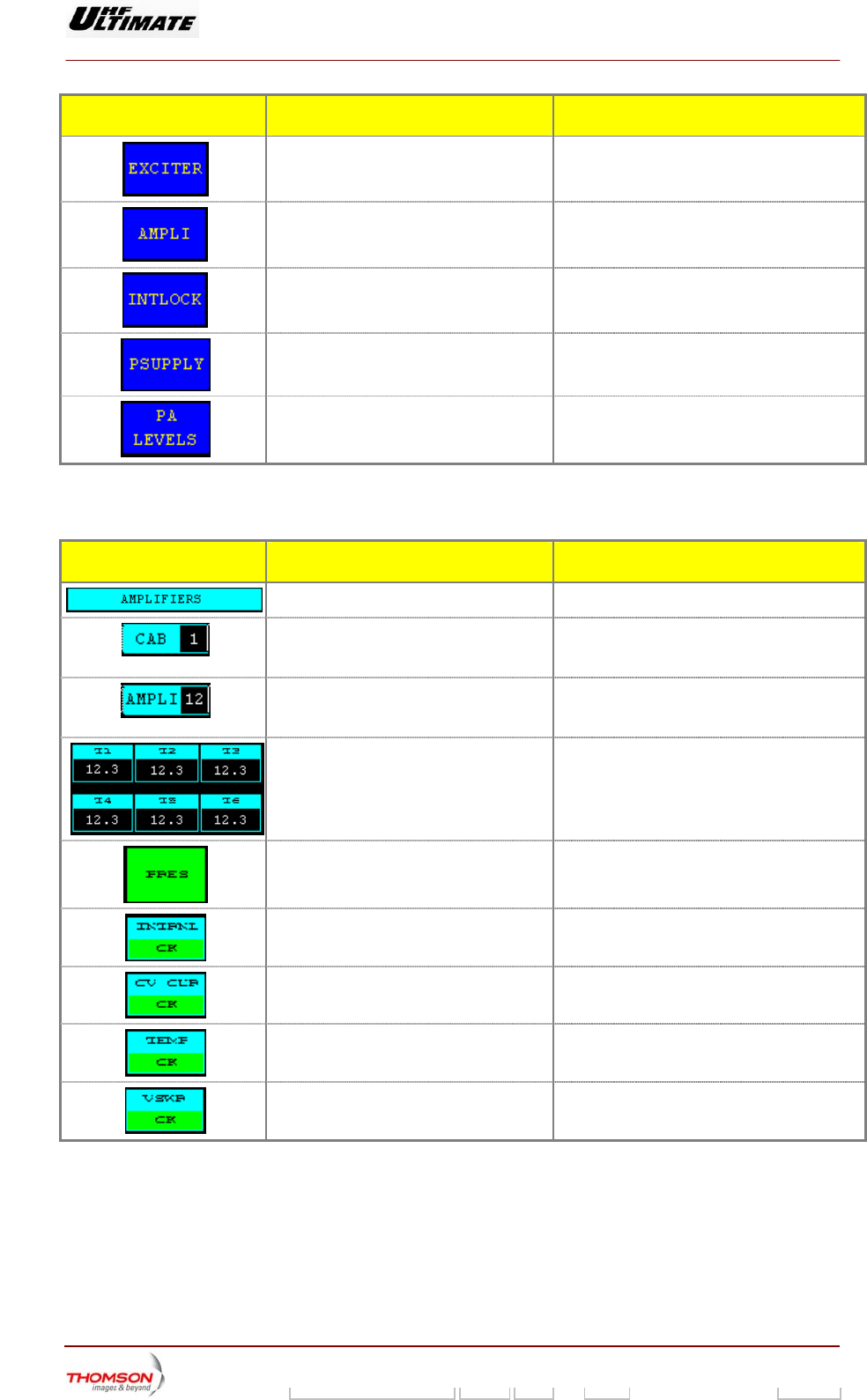
CONTROL KEYS FUNCTIONS DISPLAY/COMMENTS
Calls up the "EXCITER Level 1" window.
Calls up the "AMPLIFIERS" window.
Calls up the «INTERLOCK» window
Calls up the "POWER SUPPLY" window.
Calls up the "PA LEVELS" window.
* : Operating only when there is more than one cabinet.
** : Operating only when there is more than one amplifier.
MESSAGE FUNCTIONS DISPLAY/COMMENTS
Gives the window name.
Shows the number of the particular cabinet
to which the data displayed in this window
refer.
Shows the number of the particular
amplifier to which the data displayed in this
window refer.
Displays the analogue values of the
currents in the transistors T1 to T6.
Indicates whether the amplifier is present
or missing.
PRES / MISSING (1)
Indicates the status of the amplifier auto
diagnostic system.
INTRNL OK / INTRNL FAULT (1)
INTRNL: Internal
Indicates the status of the amplifier
Overdrive (RF current) protection system.
OV CUR OK / OV CUR FAULT (1)
Indicates the status of the amplifier
temperature protection system.
TEMP OK / TEMP FAULT (1)
Indicates the status of the amplifier SWR
protection system.
VSWR OK / VSWR FAULT (1)
(1) A fault-free status is displayed in normal video (on black background or green background in case
of colour tactile screen). A faulty status is displayed in reverse video (on white background or red
background in case of colour tactile screen). The transmitter can operate while the status of the
diagnostic systems of one or several RF amplifiers is "FAULT".
9932 V2
45321648.01 108 B E Checked 156 / 192
Numéro / Number Doc. Rev. Lan
g
u. 27/06/2006 Pa
g
e
Digital Liquid Cooled UHF
TV Equipment
Use of commands and description of indicators
Information contained is this document is confidential, is THOMSON property and cannot be disclosed in whatever form without prior written authorization of THOMSON.
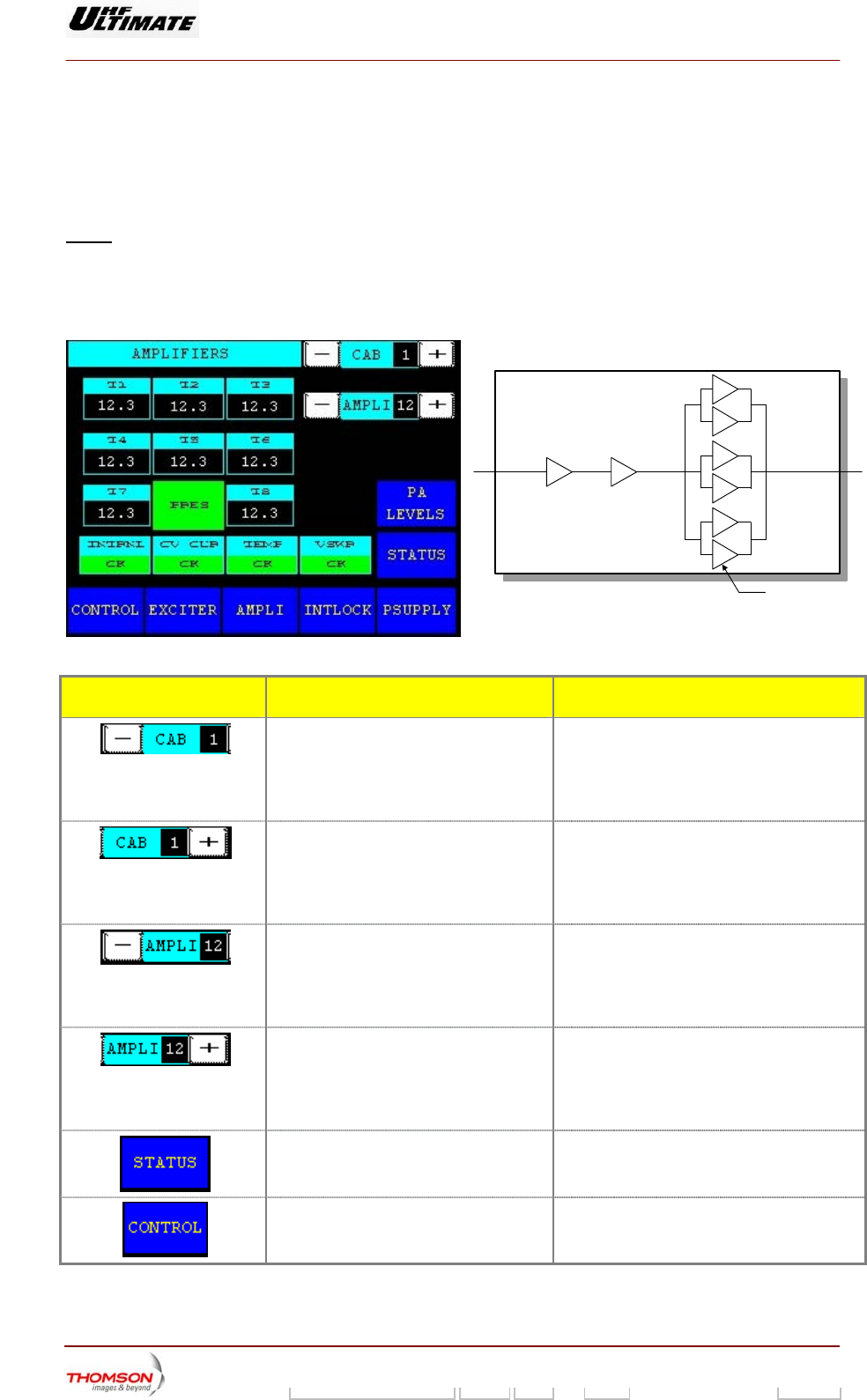
MILY ONLY) 2.1.48. "RF AMPLIFIERS" window, 8 current values (OPTIMUM FA
This window is called up by the "AMPLI" command in the other windows.
It displays the status of an RF amplifier.
Notes : An amplifier which is not included in the transmitter configuration can not be
accessed by the keys "± AMPLI".
A cabinet which is transmitter configuration can not be
accessed by the "± CAB" control keys.
not included in the
T8 T7
T1
T2
T3
T4
T5
T6
Transistor T6
99/123(f )
POWER
AMPLIFIER
CONTROL KEYS FUNCTIONS DISPLAY/COMMENTS
Decrements the cabinet number (*). The number resulting from the decrêmentation
is displayed in the message window between
the "+ CAB" and "- CAB" control keys.
Command is disabled while the PCL is locked
(disabled).
Increments the cabinet number (*). The number resulting from the incrementation
is displayed in the message window between
the "+ CAB" and "- CAB" control keys.
Command is disabled while the PCL is locked
(disabled).
Decrements t
particular cabin
The number resulting from the decrementation
is displayed in the message window between
the "+ AMPLI" and "- AMPLI" control keys.
Command i locked
(disabled).
he amplifier number in a
et (**).
s disabled while the PCL is
Increments the amplifier number in a
particular
The
cabinet (**).
umber resulting from the incrementation
is displayed in the message window between
AMPLI" and "- AMPLI" control keys.
mmand is disabled while the PCL is locked
(disabled).
n
the
Co
"+
Calls up the "TRANSMITTER STATUS"
window.
Calls up the "CONTROL Level 1" window.
9932 V2
45321648.01 108 B E Checked 157 / 192
Numéro / Number Doc. Rev. Lan
g
u. 27/06/2006 Pa
g
e
Digital Liquid Cooled UHF
TV Equipment
Use of commands and description of indicators
Information contained is this document is confidential, is THOMSON property and cannot be disclosed in whatever form without prior written authorization of THOMSON.
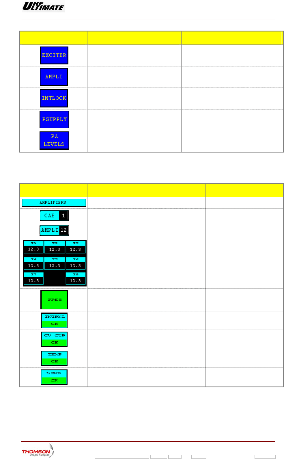
CONTROL KEYS FUNCTIONS DISPLAY/COMMENTS
Calls up the "EXCITER Level 1" window.
Calls up the "AMPLIFIERS" window.
Calls up the «INTERLOCK» window
Calls up the "POWER SUPPLY" window.
Calls up the "PA LEVELS" window.
* : Operating only when the
** : Operating only when th plifier.
re is more than one cabinet.
ere is more than one am
MESSAGE FUNCTIONS DISPLAY/COMMENTS
Gives the window name.
Shows the number of the particular cabinet to w
the data displayed in this window refer.
hich
Shows the number of the particular amplifier to w
the data displayed in this window refer.
hich
Displays the analogue values of the currents in the
transistors T1 to T8.
Indicates wheth
er the amplifier is present or missing. PRES / MISSING (1)
Indicates the status of the amplifier
system.
auto diagnostic INTRNL OK / INTRNL FAULT (1)
INTRNL: Internal
Indicates the status of the amplifier Overdrive (RF
current) protection system.
OV CUR OK / OV CUR FAULT (1)
Indicates the status of the amplifier temperature
protection system.
TEMP OK / TEMP FAULT (1)
Indicates the status of the amplifier SWR protection
system.
VSWR OK / VSWR FAULT (1)
(1) A fault-free status is displayed in normal video (on black background or green background in case
of colour tactile screen). A faulty status is displayed in reverse video (on white background or red
background in case of colour tactile screen). The transmitter can operate while the status of the
diagnostic systems of one or several RF amplifiers is "FAULT".
9932 V2
45321648.01 108 B E Checked 158 / 192
Numéro / Number Doc. Rev. Lan
g
u. 27/06/2006 Pa
g
e
Digital Liquid Cooled UHF
TV Equipment
Use of commands and description of indicators
Information contained is this document is confidential, is THOMSON property and cannot be disclosed in whatever form without prior written authorization of THOMSON.
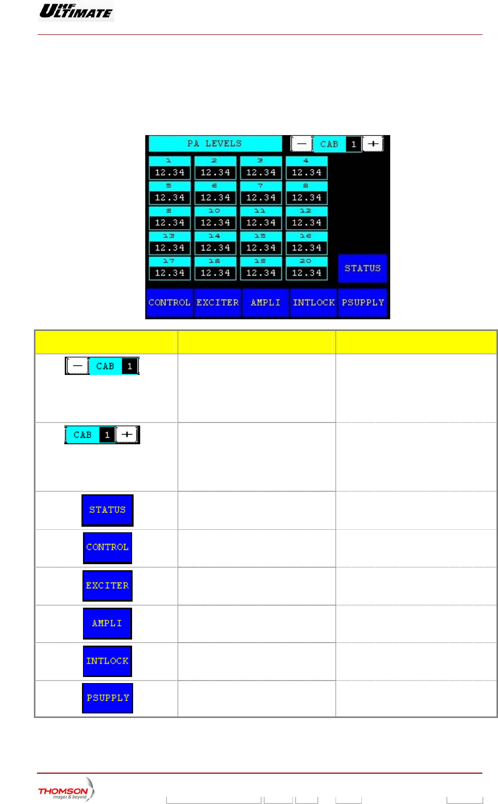
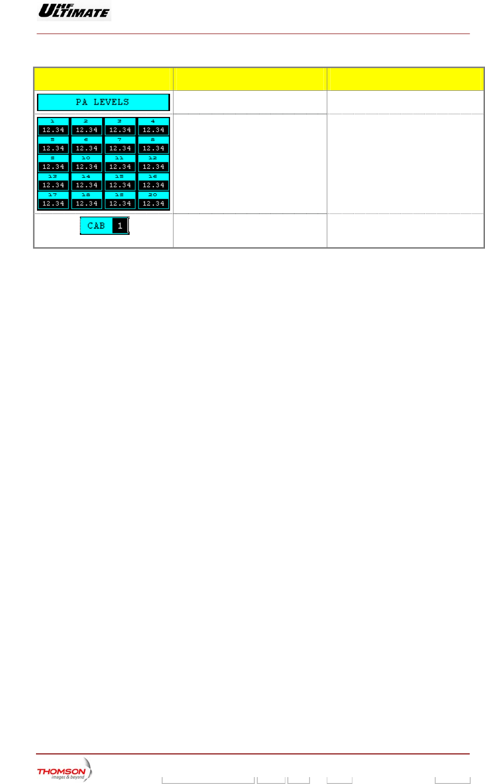
2.1.49. "PA LEVELS" window (OPTIMUM AND ULTIMATE FAMILIES ONLY)
It is called up by pressing t P
This window displays the AGC voltage values for power amplifiers in selected cabinet.
he "PA LEVELS" control key in the "AM LIFIER" window.
CONTROL KEYS FUNCTIONS DISPLAY/COMMENTS
(*)
Increments the cabinet number. The number resulting from the
incrementation is displayed in the
message window between the "+ CAB"
and "- CAB" control keys.
Command is disabled while the PCL is
locked (disabled).
(*)
Decrements the cabinet number. The number resulting from the
decrementation is displayed in the
message window between the "+ CAB"
and "- CAB" control keys.
Command is disabled while the PCL is
locked (disabled).
Calls up the "TRANSMITTER STATUS"
window.
Calls up the "CONTROL MAINT Level 2"
window.
Calls up the "EXCITER Level 1" window.
Calls up the "AMPLIFIERS" window.
Calls up the «INTERLOCK» window
Calls up the "POWER SUPPLY" window.
(*) : Operating only when there is more than one cabinet.
9932 V2
45321648.01 108 B E Checked 159 / 192
Numéro / Number Doc. Rev. Lan
g
u. 27/06/2006 Pa
g
e
Digital Liquid Cooled UHF
TV Equipment
Use of commands and description of indicators
Information contained is this document is confidential, is THOMSON property and cannot be disclosed in whatever form without prior written authorization of THOMSON.
MESSAGE FUNCTIONS DISPLAY/COMMENTS
Gives the window name.
Displays the AGC voltages for amplifiers
1 to 20 for the selected cabinet
Indicates the number of the particular
cabinet for which data (AGC voltages)
are displayed in the window.
9932 V2
45321648.01 108 B E Checked 160 / 192
Numéro / Number Doc. Rev. Lan
g
u. 27/06/2006 Pa
g
e
Digital Liquid Cooled UHF
TV Equipment
Use of commands and description of indicators
Information contained is this document is confidential, is THOMSON property and cannot be disclosed in whatever form without prior written authorization of THOMSON.
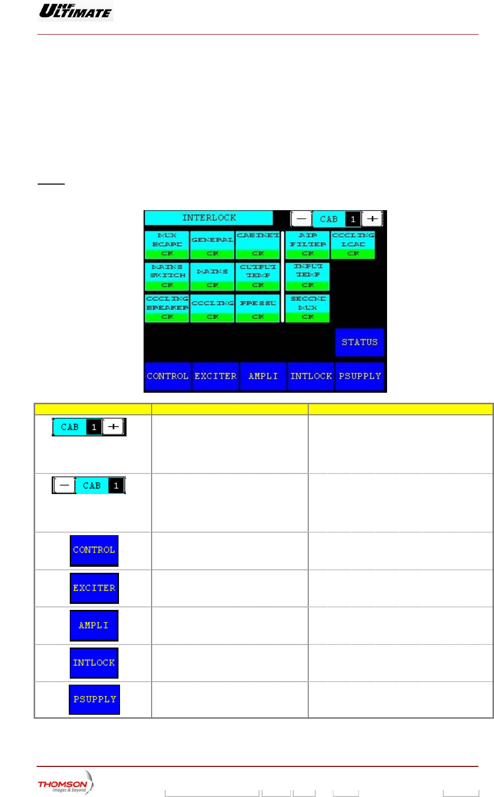
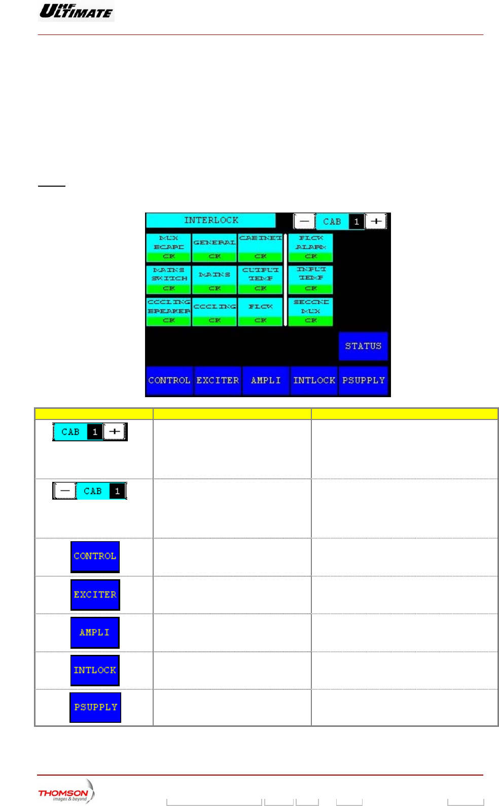
2.1.50. "AIR INTERLOCK" window (OPTIMUM AND ULTIMATE FAMILIES ONLY)
This window is called up by pressing the "INTLOCK" control keys in the other windows.
This window displays the status of the surveillance devices in the cabinet protection system. The data
signals from the sensors are arranged in the order of their physical positioning in the cabinet (from left
to right and from bottom to top). The data to the left of the vertical bar in the window trigger an
emergency shutdown when the associated fault occurs; those to the right of the bar leave the
transmitter in operation.
Note : A cabinet which is not included in the transmitter configuration can not be
accessed by the "± CAB" control keys.
CONTROL KEYS FUNCTIONS DISPLAY/COMMENTS
(*)
Inc mber resulting from the incrementation is
displayed in the message window between the
"+ CAB" and "- CAB" control keys.
Command is disabled while the PCL is locked
(disabled).
rements the cabinet number. The nu
(*)
Decrements the cabinet number. The number resulting from the decrementation is
display d in the message window between the
"+ CAB" and "- CAB" control keys.
Command is disabled while the PCL is locked
(disabled).
e
Calls up the "CONTROL Level 1"
window.
Calls up the "EXCITER Level 1" window.
Calls up the "AMPLIFIERS"
window.
Calls up the «INTERLOCK» window.
Calls up the "POWER SUPPLY" window.
9932 V2
45321648.01 108 B E Checked 161 / 192
Numéro / Number Doc. Rev. Lan
g
u. 27/06/2006 Pa
g
e
Digital Liquid Cooled UHF
TV Equipment
Use of commands and description of indicators
Information contained is this document is confidential, is THOMSON property and cannot be disclosed in whatever form without prior written authorization of THOMSON.
CONTROL KEYS FUNCTIONS DISPLAY/COMMENTS
Calls up the "TRANSMITTER STATUS"
window.
(*) : Operating only when there is more than one cabinet.
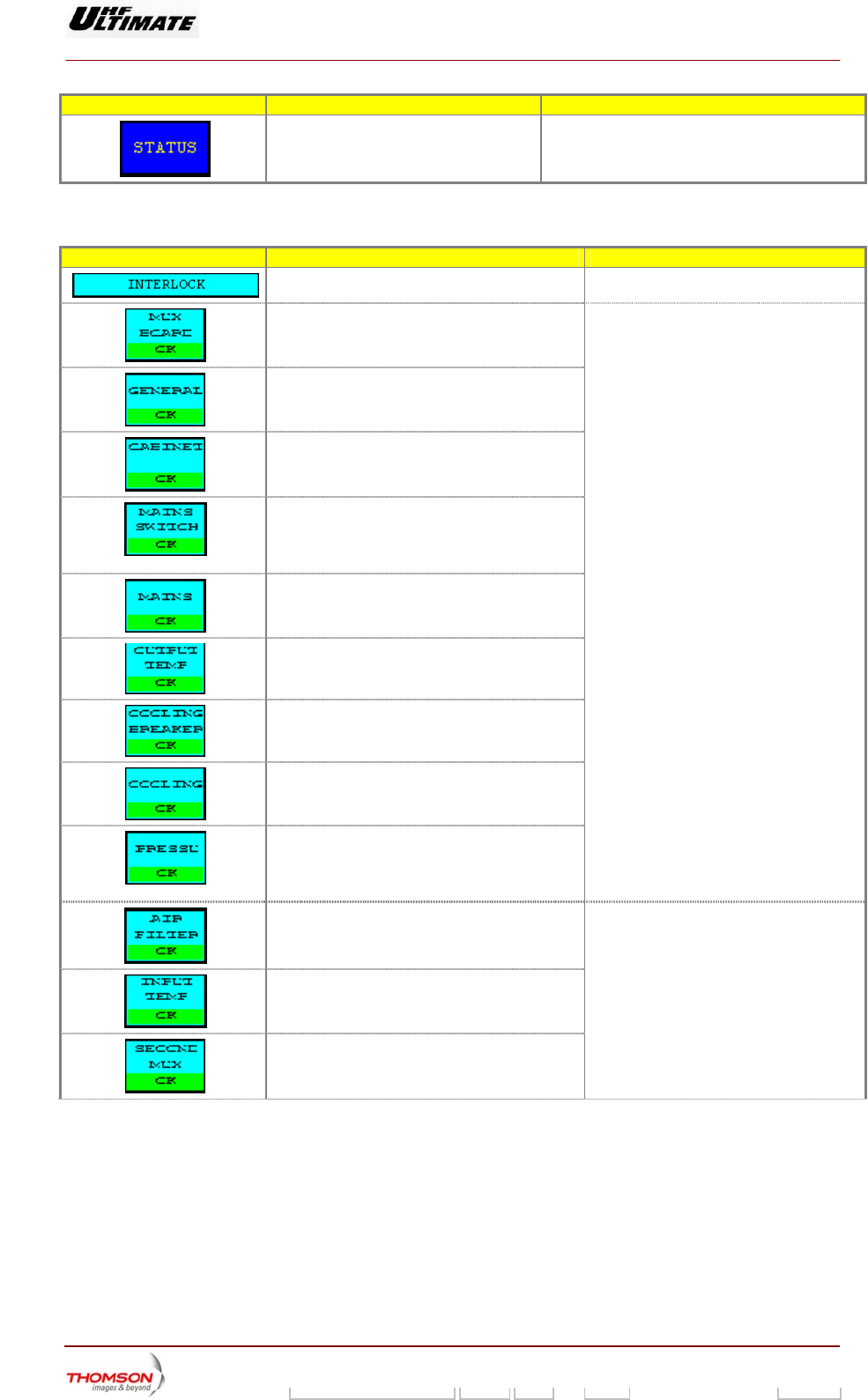
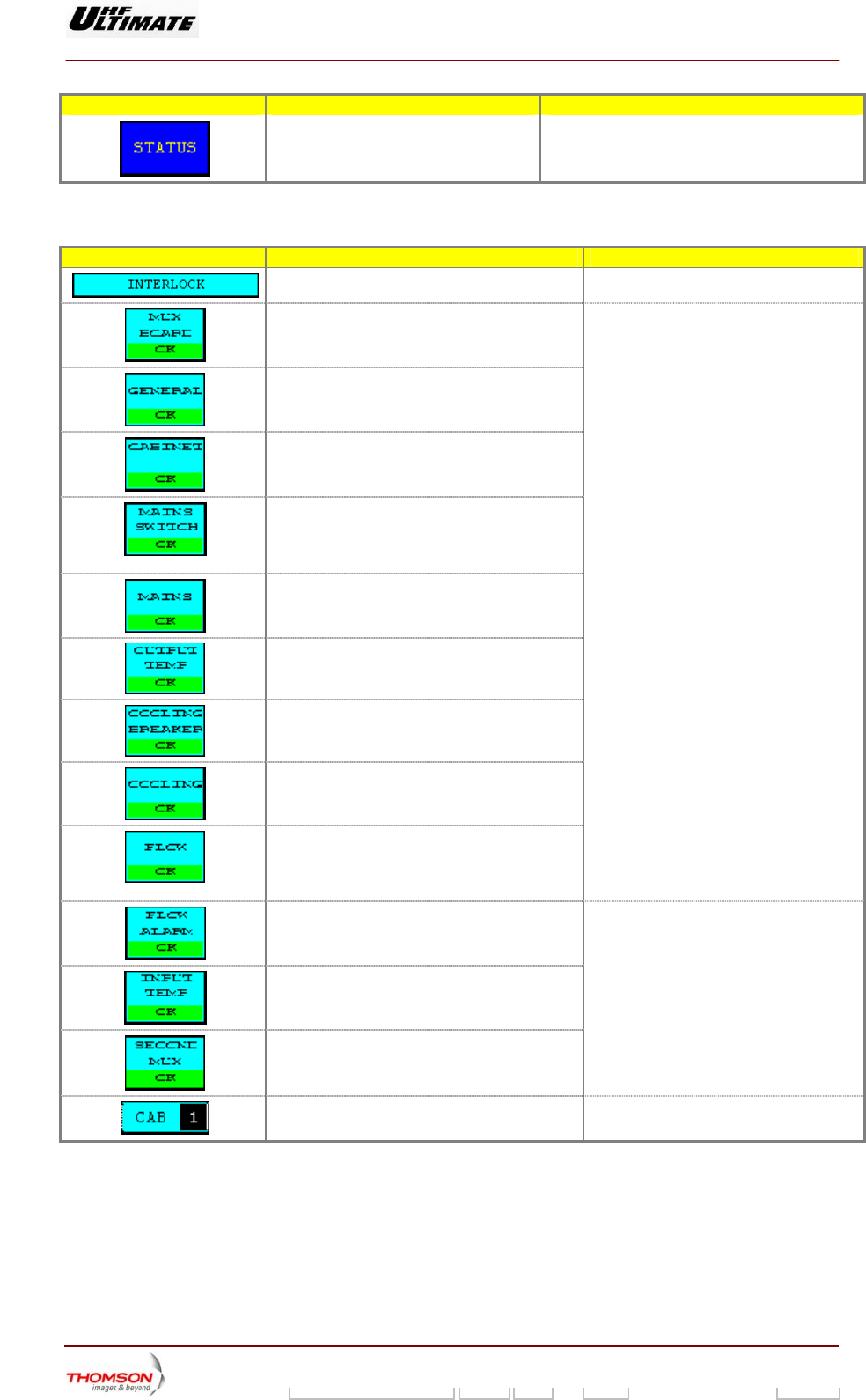
MESSAGE FUNCTIONS DISPLAY/COMMENTS
Gives the window name.
Indicates the status of the multiplex card. OK / FAULT
Indicates the status of the station protection
system.
A fault-free status is displayed in normal
video (on black background).
Indicates the status of the cabinet protection
system.
isolator (auxiliary
Indicates the status of the principal mains
contact).
A faulty status is displayed in reverse
video (on white background or red
background in case of colour tactile
screen ).
Indicates the status of the mains input (phase
order and phase
balance).
Indicates the status of the air outlet temperature
protection system.
which is detected by one of these
surveillance devices will cause a
nsmitter shutdown.
A fault
tra
Indicates the status of the cooling system po
wer
supply (presence of mains).
Indicates a cooling system fault (pump fault).
Indicates status of air pressure in the internal
cooling system of the transmitter cabinet and
also in the venti
lation system for the filtering
system.
Indicates the status of the air filter in the
external cooling system.
FAULT, OK
Indicates the status of the air inlet temperature
protection system.
d by one of these
ill not cause a
A fault which is detecte
surveillance devices w
transmitter shutdown.
Indicates the status of the other multiplex card.
9932 V2
45321648.01 108 B E Checked 162 / 192
Numéro / Number Doc. Rev. Lan
g
u. 27/06/2006 Pa
g
e
Digital Liquid Cooled UHF
TV Equipment
Use of commands and description of indicators
Information contained is this document is confidential, is THOMSON property and cannot be disclosed in whatever form without prior written authorization of THOMSON.
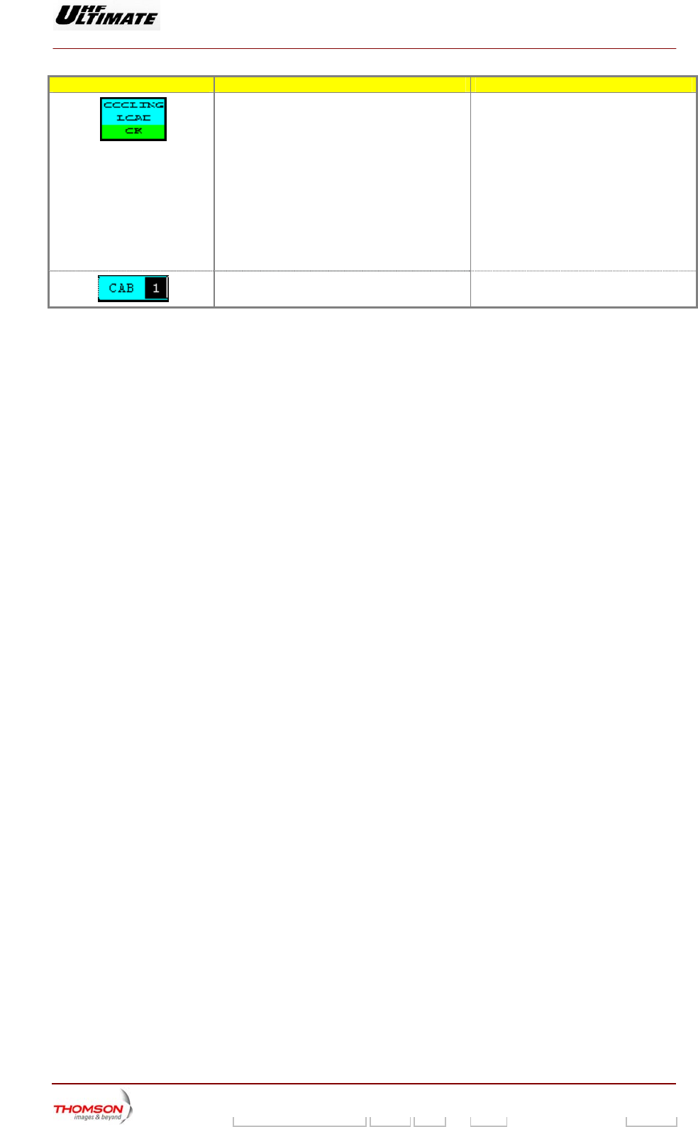
MESSAGE FUNCTIONS DISPLAY/COMMENTS
Indicates the status of the Net k Load cooling
system.
FAULT, OK
y this
se a
transmitter shutdown.
in "
ON PARAMETERS Level 1 "
indow must be on "FITTED" then this
safety is active
pposite occur (NOT FITTED),
The "COOLING LOAD" key in
wor
A fault which is detected b
surveillance device will not cau
The "COOLING LOAD" key status
INSTALLATI
w
Should the o
"INTERLOCK" window is not available.
Shows the number of t
he particular cabinet to
which the data displayed in this window refer.
9932 V2
45321648.01 108 B E Checked 163 / 192
Numéro / Number Doc. Rev. Lan
g
u. 27/06/2006 Pa
g
e
Digital Liquid Cooled UHF
TV Equipment
Use of commands and description of indicators
Information contained is this document is confidential, is THOMSON property and cannot be disclosed in whatever form without prior written authorization of THOMSON.
2.1.51. "LIQUIDE INTERLOCK" window (OPTIMUM AND ULTIMATE FAMILIES ONLY)
up by pressing the "INTLOCK" control keys in the other windows.
Th
sig
to right and ft of the vertical bar in the window trigger an
en the associated fault occurs; those to the right of the bar leave the
transmitter in
No
This window is called
is window displays the status of the surveillance devices in the cabinet protection system. The data
nals from the sensors are arranged in the order of their physical positioning in the cabinet (from left
from bottom to top). The data to the le
emergency shutdown wh
operation.
te : A cabinet which is not included in the transmitter configuration can not be
accessed by the "± CAB" control keys.
CONTROL KEYS FUNCTIONS DISPLAY/COMMENTS
(*)
The num
displaye
"+ CAB l keys.
Command is disabled while the PCL is locked
(disabled).
Increments the cabinet number. ber resulting from the incrementation is
d in the message window between the
" and "- CAB" contro
(*)
Decrements the cabinet number. The number resulting from the decrementation is
displaye
"+ CAB
Command is disabled while the PCL is locked
(disabled).
d in the message window between the
" and "- CAB" control keys.
Calls up the "CONTROL Level 1"
window.
Calls up the "EXCITER Level 1" window.
Calls up the "AMPLIFIERS" window.
Calls up the «INTERLOCK» window.
Calls up the "POWER SUPPLY" window.
9932 V2
45321648.01 108 B E Checked 164 / 192
Numéro / Number Doc. Rev. Lan
g
u. 27/06/2006 Pa
g
e
Digital Liquid Cooled UHF
TV Equipment
Use of commands and description of indicators
Information contained is this document is confidential, is THOMSON property and cannot be disclosed in whatever form without prior written authorization of THOMSON.
CONTROL KEYS FUNCTIONS DISPLAY/COMMENTS
Calls up the "TRANS
window.
MITTER STATUS"
(*) : Operating only wh is
en there more than one cabinet.
MESSAGE FUNCTIONS DISPLAY/COMMENTS
Gives the window name.
Indicates the status of the multiplex card. OK / FAULT
Indicates the status of the station protection
system.
A fault-free status is displayed in normal
video (on black background).
Indicates the status of the cabinet protection
system.
Indicates the status of the principal mains
isolator (auxiliary contact).
A faulty status is displayed in reverse
video (on white background or red
background in case of colour tactile
screen ).
Indicates the status of the mains input (phase
order and phase balance).
Indicates the status of the liquid outlet
temperature protection system.
A fault which is detected by one of these
surveillance devices will cause a
transmitter shutdown.
Indicates the status of the cooling system power
supply (presence of mains).
Indicates a cooling system fault (Motor fault).
Indicates status of the flow in the internal
cooling system of the transmitter cabinet and
also in the ventilation system for the filtering
system.
Indicates the status of the flow in the external
cooling system.
FAULT, OK
Indicates the status of the liquid inlet
temperature protection system.
A fault which is detected by one of these
surveillance devices will not cause a
transmitter shutdown.
Indicates the status of the other multiplex card.
Shows the number of the particular cabinet to
which the data displayed in this window refer.
9932 V2
45321648.01 108 B E Checked 165 / 192
Numéro / Number Doc. Rev. Lan
g
u. 27/06/2006 Pa
g
e
Digital Liquid Cooled UHF
TV Equipment
Use of commands and description of indicators
Information contained is this document is confidential, is THOMSON property and cannot be disclosed in whatever form without prior written authorization of THOMSON.
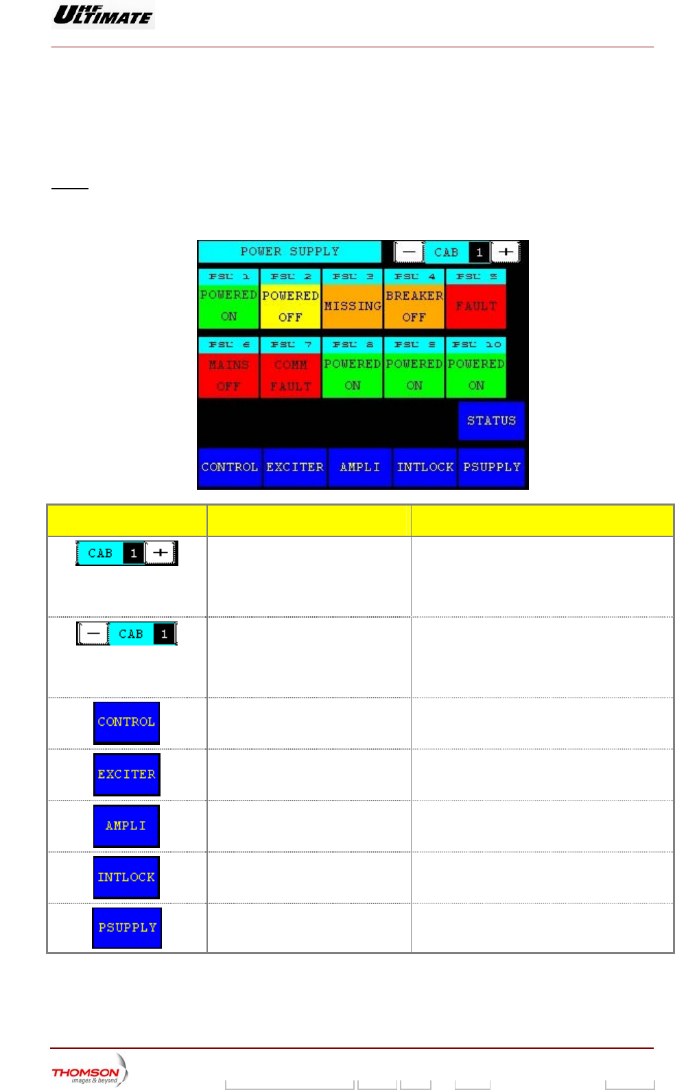
2.1.52. "POWER SUPPLY" window (OPTIMUM AND ULTIMATE FAMILIES ONLY)
This window is called up by pressing the "POWER SUPPLY" control keys in the other windows.
It displays the status of the power supplies in a particular cabinet.
Note : A power supply which is not included in the transmitter configuration will not appear. A
cabinet which is not included in the transmitter configuration can not be accessed by the
"± CAB" control keys.
CONTROL KEYS FUNCTIONS DISPLAY/COMMENTS
Increments the cabinet number (*). The number resulting from the incrementation is
displayed in the message window between the
"+ CAB" and "- CAB" control keys.
Command is disabled while the PCL is locked
(disabled).
Decrements the cabinet number (*). The number resulting from the decrementation is
displayed in the message window between the
"+ CAB" and "- CA" control keys.
Command is disabled while the PCL is locked
(disabled).
Calls up the "CONTROL Level 1"
window.
Calls up the "EXCITER Level 1"
window.
Calls up the "AMPLIFIERS" window.
Calls up the «INTERLOCK» window
Calls up the "POWER SUPPLY"
window.
9932 V2
45321648.01 108 B E Checked 166 / 192
Numéro / Number Doc. Rev. Lan
g
u. 27/06/2006 Pa
g
e
Digital Liquid Cooled UHF
TV Equipment
Use of commands and description of indicators
Information contained is this document is confidential, is THOMSON property and cannot be disclosed in whatever form without prior written authorization of THOMSON.
CONTROL KEYS FUNCTIONS DISPLAY/COMMENTS
Calls up the "TRANSMITTER
STATUS" window.
(*) : Operating only when there is more than one cabinet.
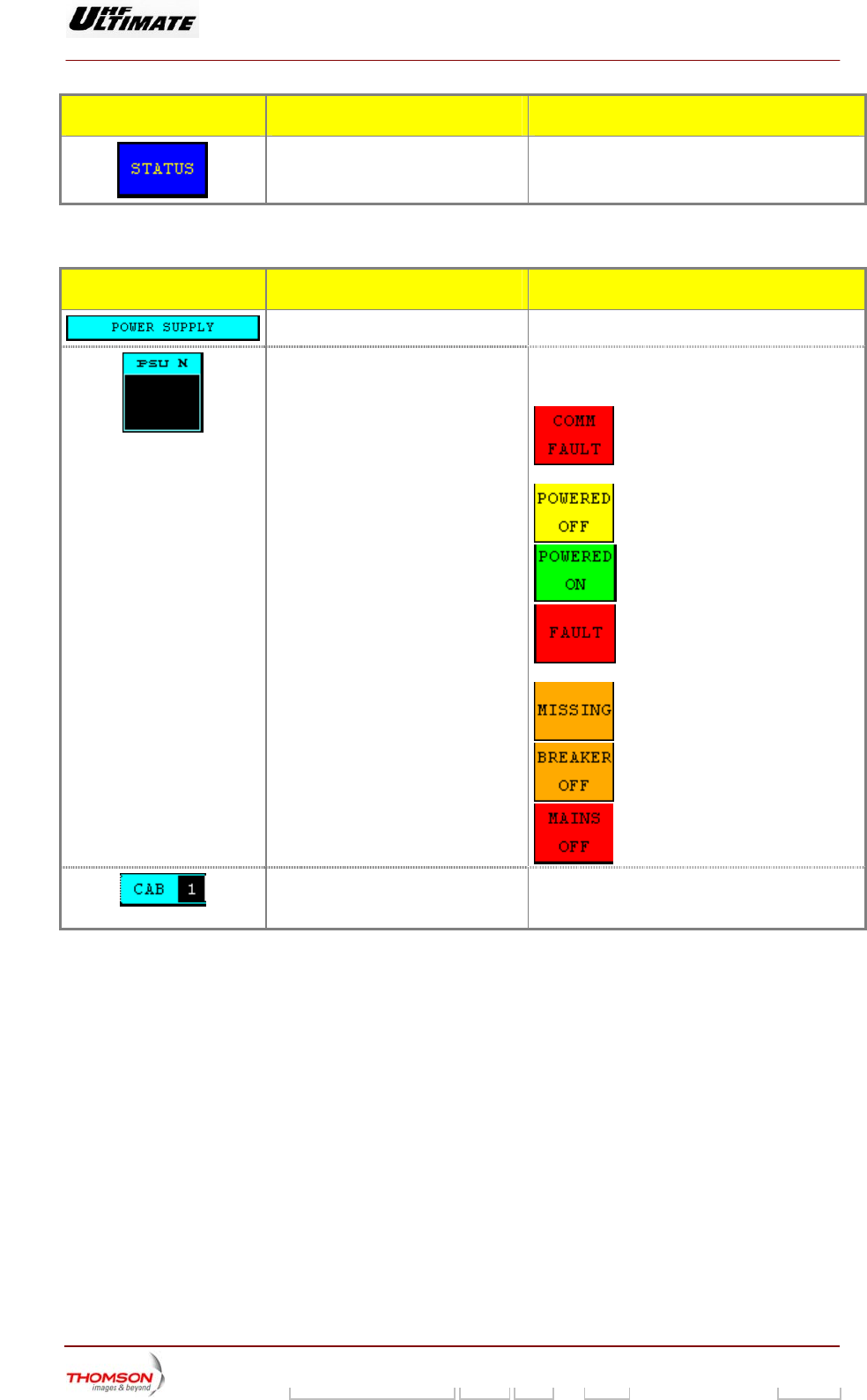
MESSAGE FUNCTIONS DISPLAY/COMMENTS
Gives the window name.
Identifies the number and status of the
power supply.
The number "n" indicates the
physical position of the power
supply in the cabinet (n = nth
position from the right when
looking from behind the
cabinet, i.e. in front of the
power supply units).
There are seven possible power supply
status conditions.
COMM FAULT, POWERED OFF, POWERED ON,
FAULT, MISSING, BREAKER OFF, MAINS
FAULT (1)
: Problem in the multiplex card
(internal power supply fault).
: PSU shut down without a fault.
: PSU operational without a fault.
: PSU faulty, independently of its
operational state (working or shut down).
: PSU missing.
: PSU isolator open.
: PSU mains fuse faulty.
Shows the number of the particular
cabinet to which the data displayed in
this window refer.
* : Operating only when there is more than one cabinet.
(1) : A fault-free status is displayed in normal video (on black background or green background in case
of colour tactile screen). A faulty status is displayed in reverse video (on white background or red
background in case of colour tactile screen).
9932 V2
45321648.01 108 B E Checked 167 / 192
Numéro / Number Doc. Rev. Lan
g
u. 27/06/2006 Pa
g
e
Digital Liquid Cooled UHF
TV Equipment
Use of commands and description of indicators
Information contained is this document is confidential, is THOMSON property and cannot be disclosed in whatever form without prior written authorization of THOMSON.
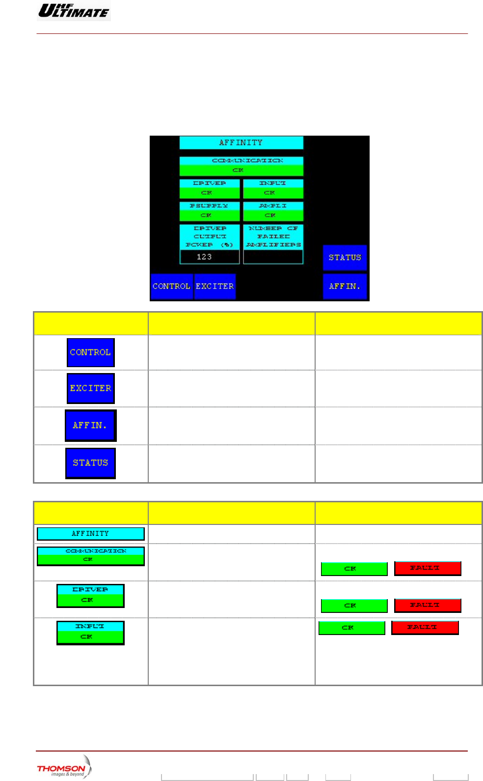
2.1.53. "AFFINITY" window (AFFINITY FAMILY ONLY)
This window is called up by the "AFFINITY" command in the other windows.
It displays the status of the Driver/RF Amplifier AFFINITY rack. This windows is only available with the
AFFINITY transmitter.
CONTROL KEYS FUNCTIONS DISPLAY/COMMENTS
Calls up the "CONTROL Level 1" window.
Calls up the "EXCITER Level 1" window.
Calls up the "AFFINITY" window.
Calls up the "TRANSMITTER STATUS"
window.
MESSAGE FUNCTIONS DISPLAY/COMMENTS
Gives the window name.
Indicates the status of the communication
between the CPU board and the MSI board
of Driver/Amplifier rack .
OK / FAULT
/
Indicates the status of the Driver section . OK / FAULT
/
Indicates the level status of the RF input
signal on the relevant driver section
according with the threshold value. The
MODAP Exciter must be “ON”.
The nominal input value is : + 6dBM
/
OK : RF input signal > + 1dBm
Fault : RF input signal < + 1dBm
The threshold value is + 1dbm
9932 V2
45321648.01 108 B E Checked 168 / 192
Numéro / Number Doc. Rev. Lan
g
u. 27/06/2006 Pa
g
e
Digital Liquid Cooled UHF
TV Equipment
Use of commands and description of indicators
Information contained is this document is confidential, is THOMSON property and cannot be disclosed in whatever form without prior written authorization of THOMSON.
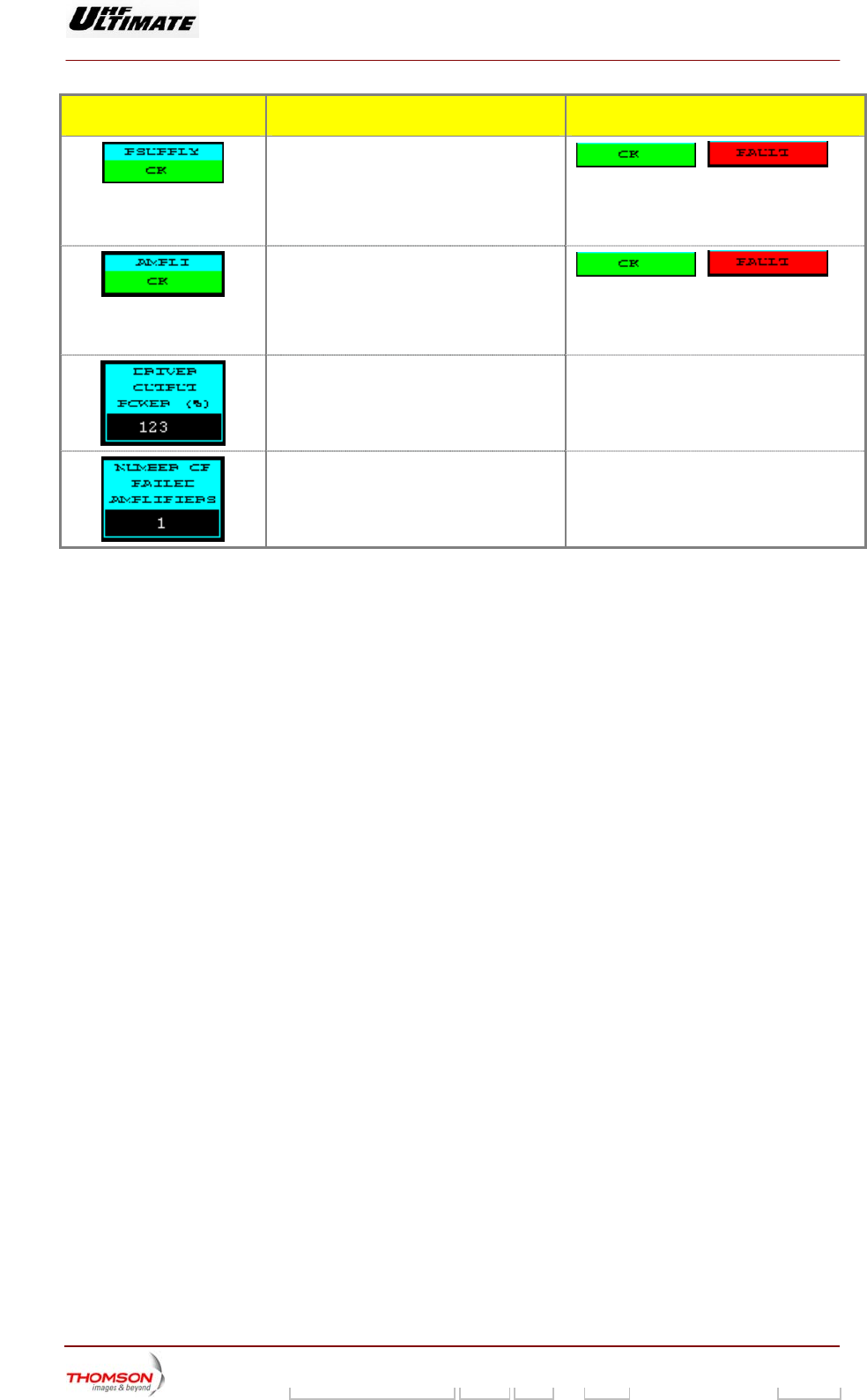
MESSAGE FUNCTIONS DISPLAY/COMMENTS
Indicates the status of the final power supply
unit .
/
OK : All final PSU are correct.
Fault: The mistake is coming from one of the
final PSU.
Indicates the status of the RF amplifier
Affinity rack /
OK : All RF amplifier segments are correct.
Fault : The mistake is coming from one of
the RF amplifier segment
Displays the transmitted RF output power
value of the driver
This value is expressed as a percentage of
the calibrated power value according with
your installation choice
Displays the failure amplifier number
including into RF amplifier Affinity rack
Values: 1 to 8
9932 V2
45321648.01 108 B E Checked 169 / 192
Numéro / Number Doc. Rev. Lan
g
u. 27/06/2006 Pa
g
e
Digital Liquid Cooled UHF
TV Equipment
Use of commands and description of indicators
Information contained is this document is confidential, is THOMSON property and cannot be disclosed in whatever form without prior written authorization of THOMSON.
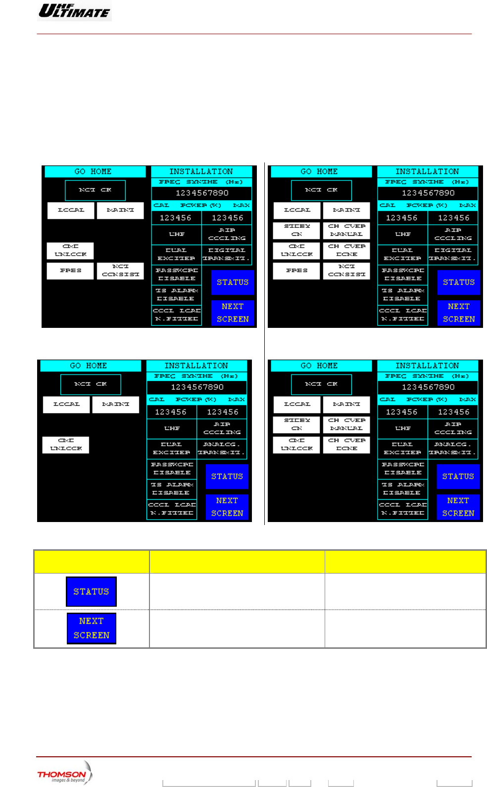
2.1.54. "GO HOME AND VIEW INSTALL. PARAMETERS" window
This window is called up by pressing on the "STATUS" message window in the "STATUS" window or
ATUS" message window in the "TRANSMITTER STATUS" window.
It provides information firstly in regard to the "GO HOME" status condition and secondly in regard to
the equipment installation parameters.
Digital Transmitter
on the "TRANSMITTER ST
Figure 34 : Single Drive configuration Figure 35 : Dual Drive configuration
Analogue Transmitter
CONTROL KEYS FUNCTIONS DISPLAY/COMMENTS
Calls up the "TRANSMI
window.
TTER STATUS"
Calls up the "VIEW TRANSMITTER
INTERFA ON PARAMETERS"
window.
CE INSTALLATI
9932 V2
45321648.01 108 B E Checked 170 / 192
Numéro / Number Doc. Rev. Lan
g
u. 27/06/2006 Pa
g
e
Digital Liquid Cooled UHF
TV Equipment
Use of commands and description of indicators
Information contained is this document is confidential, is THOMSON property and cannot be disclosed in whatever form without prior written authorization of THOMSON.
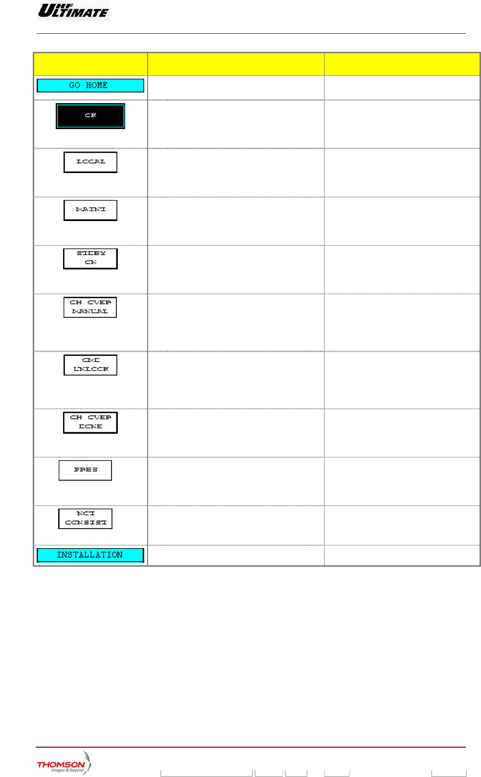
MESSAGE FUNCTIONS DISPLAY/COMMENTS
Displays the title of the columns on the left hand
side.
Indicates OK / NOT OK
itions
is not satisfied the "NOT OK" signal will
the "GO HOME" status.
As long one of the "GO HOME" cond
be given.
This mes
which GO
Operating mode is in local mode.
Level 1" window
provides for selecting the transmitter
operating mode (LOCAL / REMOTE).
sage window indicates a condition for
HOME is NOT OK.
LOCAL, invisible if not (1).
The "CONTROL
This message window indicates a condition for
which GO HOME is NOT OK.
Operating mode is in maintenance mode.
MAINT, invisible if not (1).
The "CONTROL Level 1" window
provides for selecting the transmitter
operating mode (MAINT / NORMAL).
This message window indicates a condition for
which GO HOME is NOT OK. (*)
Reserve exciter in operation.
STDBY ON, invisible if not.
The "CONTROL Level 1" window
provides for start-up of the reserve exciter
(STDBY ON / STDBY OFF).
This message window indicates a condition for
which GO HOME is NOT OK. (*)
Manual changeover mode.
CH OVER MANUAL, invisible if not.
The "EXCITER Level 1" window provides
for selecting the transmitter changeover
mode (CH OVER MAN / CH OVER
AUTO).
This message window indicates a condition for
which GO HOME is NOT OK.
CMD UNLOCK, invisible if not.
Local user interface not locked. locking the local user interface window; it
is imperative to finish in this condition, i.e.
The "STATUS" window provides for
the "Go Home" LED is extinguished.
which GO HOME is NOT OK
Automatic changeo
This message window indicates a condition for
. (*)
ver of the exciter has
CH OVER DONE, invisible if not.
The RESET button in the front of the PCL
provides for re-initialising the changeover
system (CH OVER NOT DONE).
already been carried out.
** wh
This message window indicates a condition for
ich GO HOME is NOT OK.
The input signal to the digital exciter unit is the
RBS sig
PRBS, invisible if not.
P nal.
**
This mes
which GO
The modu
sage window indicates a condition for
HOME is NOT OK.
NOT CONSIST., invisible if not.
lator status is inconsistent.
Title for right hand columns.
9932 V2
45321648.01 108 B E Checked 171 / 192
Numéro / Number Doc. Rev. Lan
g
u. 27/06/2006 Pa
g
e
Digital Liquid Cooled UHF
TV Equipment
Use of commands and description of indicators
Information contained is this document is confidential, is THOMSON property and cannot be disclosed in whatever form without prior written authorization of THOMSON.
MESSAGE FUNCTIONS DISPLAY/COMMENTS
The display of these parameters serves solely
as a summary of the installation configuration.
The configuration parameters are
accessible in the "INSTALLATION"
window.
* : Only Dual-Drive version
**: Only available in Digital Transmitter
(1) If the GOHOME condition is satisfied the associated signal will disappear.
9932 V2
45321648.01 108 B E Checked 172 / 192
Numéro / Number Doc. Rev. Lan
g
u. 27/06/2006 Pa
g
e
Digital Liquid Cooled UHF
TV Equipment
Use of commands and description of indicators
Information contained is this document is confidential, is THOMSON property and cannot be disclosed in whatever form without prior written authorization of THOMSON.
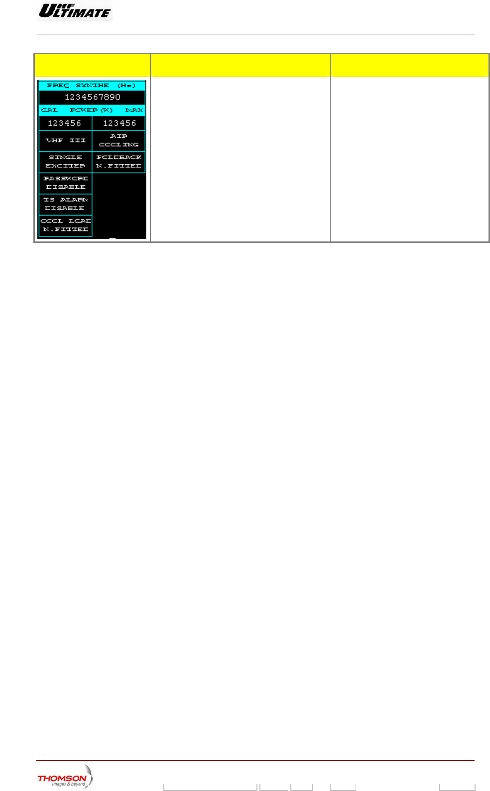
2.1.55. "VIEW TRANSMITTER INTERFACE INSTALLATION PARAMETERS" window
This window is called up by pressing on the "NEXT SCREEN" message window in the "GO HOME
AND VIEW INSTALLATION PARAMETERS" window.
CONTROL KEYS FUNCTIONS DISPLAY/COMMENTS
Calls up the "TRANSMITTER STATUS"
window.
Calls up the
"VIEW CABINET
CONFIGURATION " window.
MESSAGE FUNCTIONS DISPLAY/COMMENTS
This message window indicates the transmitter
ID number in N+1 or Passive Reserve
configurations.
The transmitter ID number is used for
remote control through an RS 232/485
connection.
This message window indicates the type of
JBUS protocol operation for remote control
JBUS ASCII
JBUS RTU
This message window indicates the type of
remote operation.
SERIAL RMT CTRL, PARALLEL RMT
CTRL, USER RMT CTRL
This message window indicates the language of
the Local Control Panel windows.
FRANCAIS, ENGLISH, ESPAGNOL
This message window indicates the type of
power unity.
DISPLAY IN dB/W, DISPLAY IN %
This message window indicates if the CPU
software is adapted to suit the safety interface
hardware.
COOL REDUND NOT FITTED. ;
COOL REDUND FITTED
9932 V2
45321648.01 108 B E Checked 173 / 192
Numéro / Number Doc. Rev. Lan
g
u. 27/06/2006 Pa
g
e
Digital Liquid Cooled UHF
TV Equipment
Use of commands and description of indicators
Information contained is this document is confidential, is THOMSON property and cannot be disclosed in whatever form without prior written authorization of THOMSON.
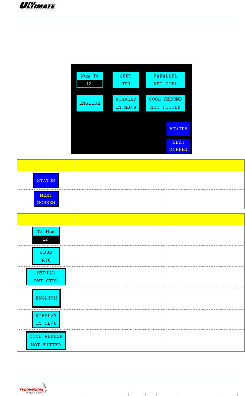
2.1.56. "VIEW CABINET CONFIGURATION INSTALLATION PARAMETERS" window
This window is called up by pressing on the "NEXT SCREEN" message window in the "VIEW
TRANSMITTER INTERFACE INSTALLATION PARAMETERS" window.
CONTROL KEYS FUNCTIONS DISPLAY/COMMENTS
Calls up the "TRANSMITTER STATUS"
window.
♦ In case of DIGITAL transmitter calls up the "
VIEW ADAPT INSTALLATION
PARAMETERS" window
♦ In case of ANALOGUE transmitter calls up
NSTALLATION
the " VIEW EXCITER I
PARAMETERS" window
MESSA GE FUNCTIONS DISPLAY/COMMENTS
Displays the title of the window
This message window indicates the type of the
cabinet.
This message window indicates the number of
F power amplifier including to this cabinet.
the R
This message window
indicates the number of
currents measured in operation by amplifier
unit.
6 or 8
9932 V2
45321648.01 108 B E Checked 174 / 192
Numéro / Number Doc. Rev. Lan
g
u. 27/06/2006 Pa
g
e
Digital Liquid Cooled UHF
TV Equipment
Use of commands and description of indicators
Information contained is this document is confidential, is THOMSON property and cannot be disclosed in whatever form without prior written authorization of THOMSON.
INSTALLATION PARAMETERS" window
message window in the " VIEW
ATION PARAMETERS " window.
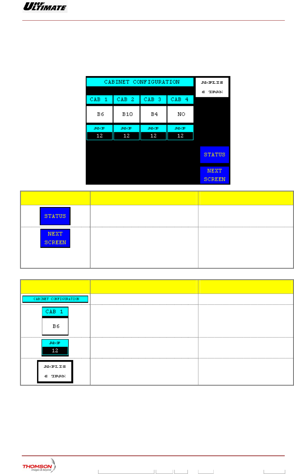
2.1.57. "VIEW ADAPT
This window is called up by pressing on the "NEXT SCREEN"
CABINET CONFIGURATION INSTALL
Figure 36 : MODAP Version Figure 37 : SIRIUS Version
CONTROL KEYS FUNCTIONS DISPLAY/COMMENTS
Calls up the "TRANSMITTER STATUS"
window.
Calls up the "VIEW ETHERNET
INSTALLATION PARAMETERS" window.
INDICATOR LAMPS AND
MESSAGE DISPLAYS
FUNCTIONS DISPLAY/COMMENTS
Displays which type of modulator processes
the input signal.
IFIQ BOARD / COFDM EXT /
8VSB BOARD /
8MHz COFDM BOARD/
7MHz COFDM BOARD /
6MHz COFDM BOARD /
FLO SIRIUS /
Indicates the status, of the DAP linearity
correction (ALE = Adaptive Linear Equaliser).
LIN. COR NOT FITTED /
LIN. COR ON LINE /
LIN. COR BYPASSED
Indicates the status of the DAP digital filter
correction.
DIGIT FILT NOT FITTED /
DIGIT FILT ON LINE /
DIGIT FILT BYPASSED
(2)
Indicates the bandwidth of the canal for DVB
signal (Internal DVB Modulator).
Indicates the status, ON LINE or BYPASS, of
the DAP non linearity correction (Look Up
Table).
N. LIN COR ON LINE /
N. LIN COR BYPASSED
9932 V2
45321648.01 108 B E Checked 175 / 192
Numéro / Number Doc. Rev. Lan
g
u. 27/06/2006 Pa
g
e
Digital Liquid Cooled UHF
TV Equipment
Use of commands and description of indicators
Information contained is this document is confidential, is THOMSON property and cannot be disclosed in whatever form without prior written authorization of THOMSON.
INDICATOR LAMPS AND
MESSAGE DISPLAYS
FUNCTIONS DISPLAY/COMMENTS
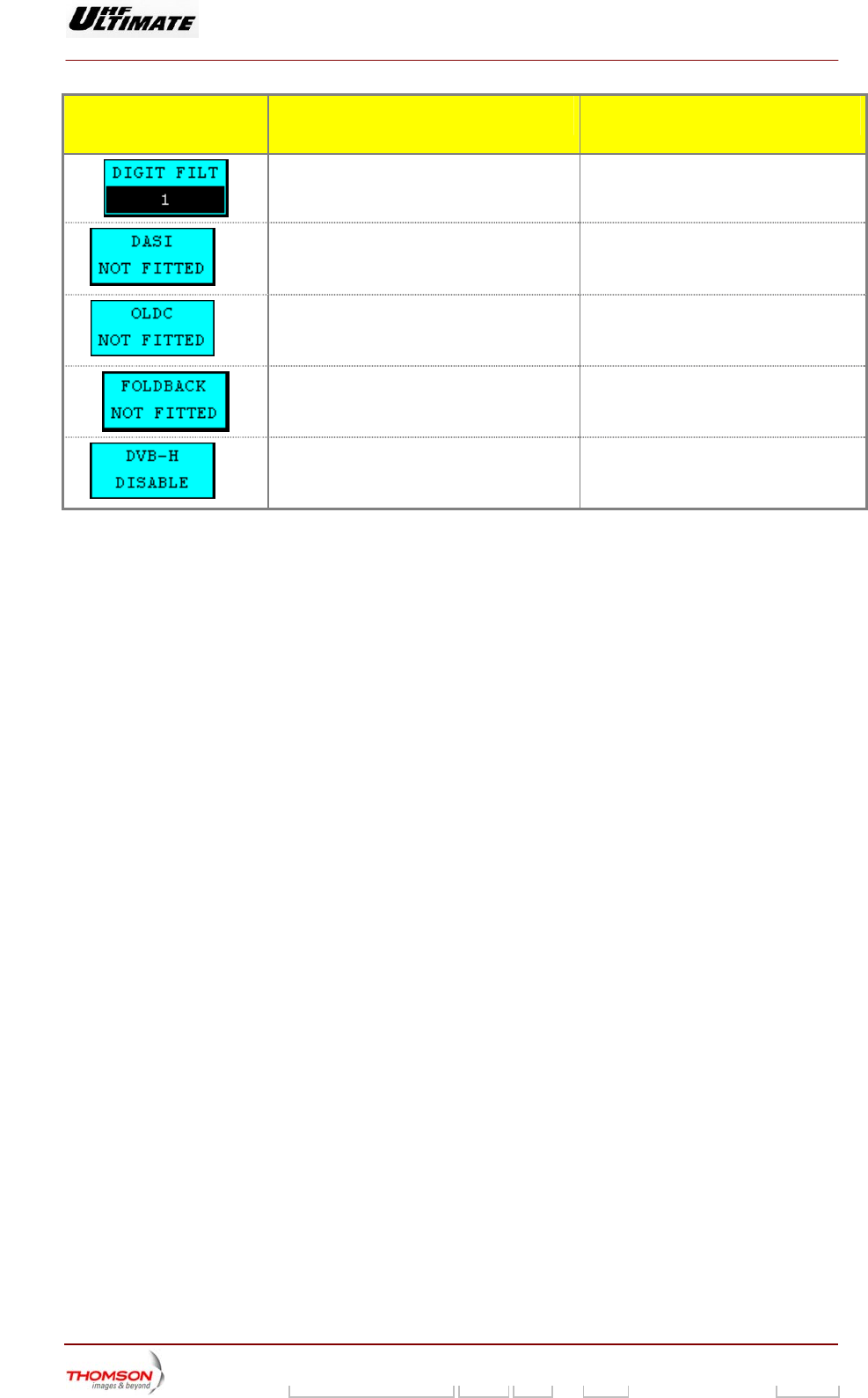
Displays th
(1 to 5).
e reference table of the digital filter
(1)
I input is present
P unit.
DASI FITTED / DASI NOT FITTED Displays whether a Double AS
or absent in the MODA
Displays whether an O
(1)
LDC unit is present or
absent in the MODAP unit.
OLDC FITTED / OLDC NOT FITTED
used is progressively.
Displays whether antenna VSWR regulation
(2)
accessible (available).
Displays whether the DVB-H parameters are Visible on COFDM SIRIUS modulator only
(1): MODAP version only.
vailable on MediaFLO modulator.
(2): Una
9932 V2
45321648.01 108 B E Checked 176 / 192
Numéro / Number Doc. Rev. Lan
g
u. 27/06/2006 Pa
g
e
Digital Liquid Cooled UHF
TV Equipment
Use of commands and description of indicators
Information contained is this document is confidential, is THOMSON property and cannot be disclosed in whatever form without prior written authorization of THOMSON.
ADAPT INSTALLATION P
♦
It prov
param
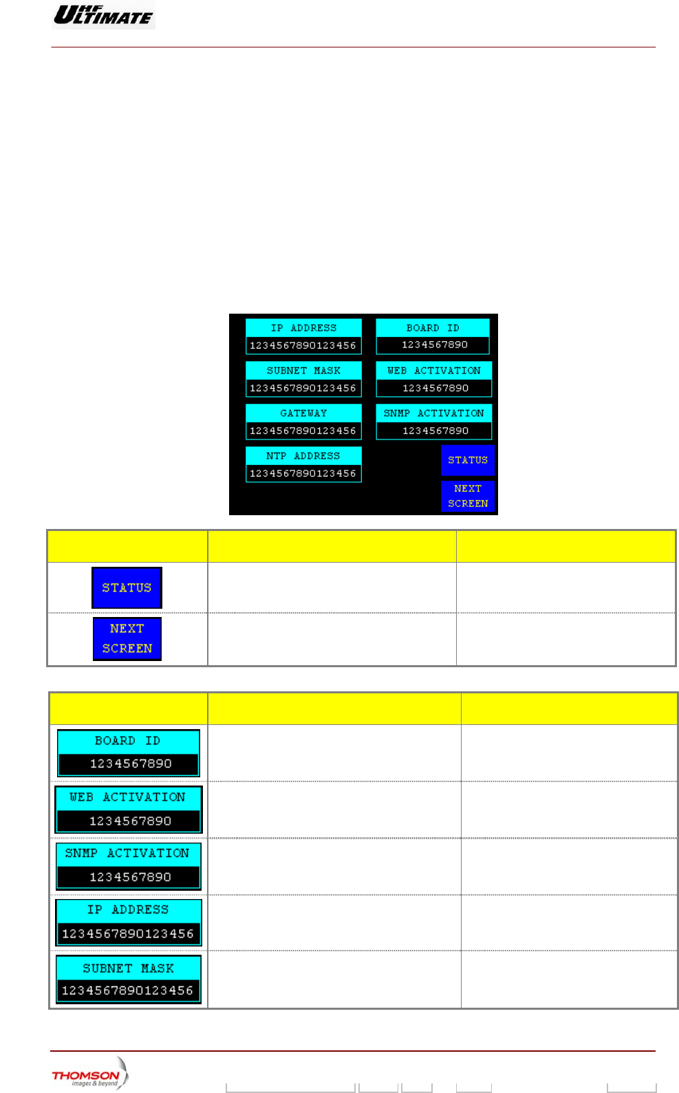
2.1.58. "VIEW ETHERNET INSTALLATION PARAMETERS" window
♦ Digital transmitter
This window is called up by pressing on the "SCREEN NEXT" message window in the "VIEW
ARAMETERS".
Analogue transmitter
This window is called up by pressing on the "SCREEN NEXT" message window in the "VIEW
EXCITER INSTALLATION PARAMETERS".
ides information on Ethernet network parameters for the transmitter, according to installation
eters. This window is only available with TH860 CPU Board.
CONTROL KEYS FUNCTIONS DISPLAY/COMMENTS
Calls up the "TRANSMITTER STATUS"
window.
Calls up the "GO HOME AND VIEW
INSTALLATION PARAMETERS"
window.
MESSAGE FUNCTIONS DISPLAY/COMMENTS
Displays the Identification number of the CPU
board.
Displays the WEB activation code value. Without option in operation the control
keys displays: “0”
Displays the SNMP activation code value. Without option in operation the control
keys displays: “0”
Displays the IP address of the transmitter. When the Ethernet network is not
operated the control keys must display:
“0.0.0.0”
Displays the sub-net mask value. When the Ethernet network is not
operated the control keys must display:
“0.0.0.0”
9932 V2
45321648.01 108 B E Checked 177 / 192
Numéro / Number Doc. Rev. Lan
g
u. 27/06/2006 Pa
g
e
Digital Liquid Cooled UHF
TV Equipment
Use of commands and description of indicators
Information contained is this document is confidential, is THOMSON property and cannot be disclosed in whatever form without prior written authorization of THOMSON.
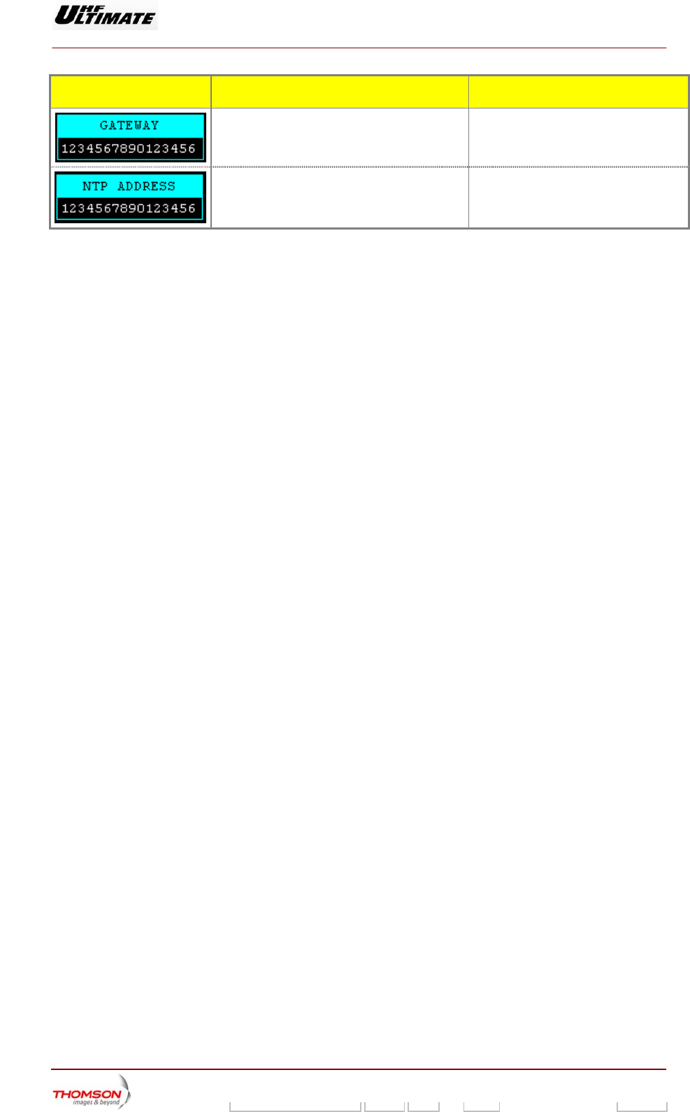
MESSAGE FUNCTIONS DISPLAY/COMMENTS
Displays the IP address of the Gateway When the Ethernet network is not
operated the control keys must display:
“0.0.0.0”
Displays the IP address of the Net work Time
Protocol (NTP) server
When the Ethernet network is not
operated the control keys must display:
“0.0.0.0”
9932 V2
45321648.01 108 B E Checked 178 / 192
Numéro / Number Doc. Rev. Lan
g
u. 27/06/2006 Pa
g
e
Digital Liquid Cooled UHF
TV Equipment
Use of commands and description of indicators
9932 V2
45321648.01 108 B E Checked 179 / 192
Numéro / Number Doc. Rev. Lan
g
u. 27/06/2006 Pa
g
e
Information contained is this document is confidential, is THOMSON property and cannot be disclosed in whatever form without prior written authorization of THOMSON.
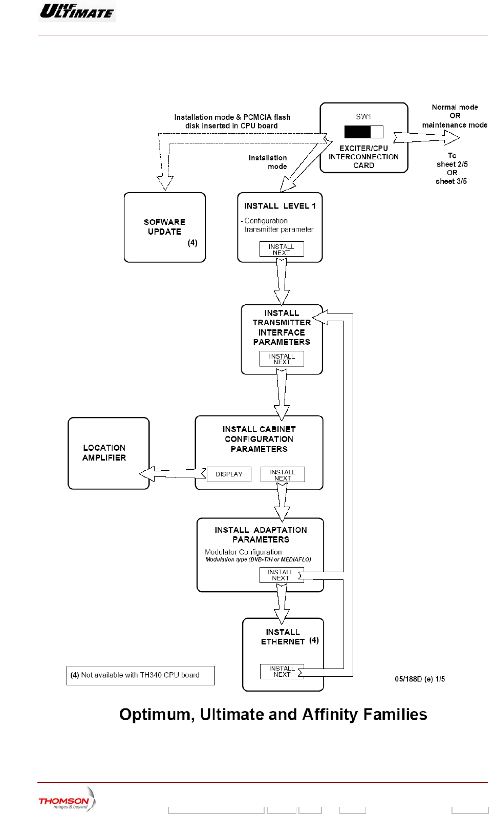
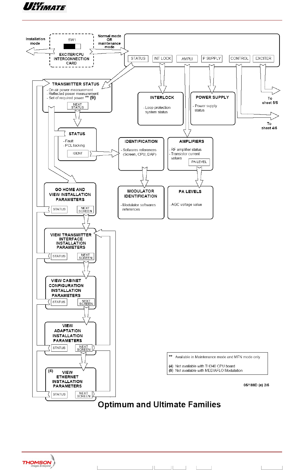
2.1.59. Navigating the PCL windows
Figure 38 : Navigation in tactile screen windows (1/5)
Digital Liquid Cooled UHF
TV Equipment
Use of commands and description of indicators
9932 V2
45321648.01 108 B E Checked 180 / 192
Numéro / Number Doc. Rev. Lan
g
u. 27/06/2006 Pa
g
e
Information contained is this document is confidential, is THOMSON property and cannot be disclosed in whatever form without prior written authorization of THOMSON.
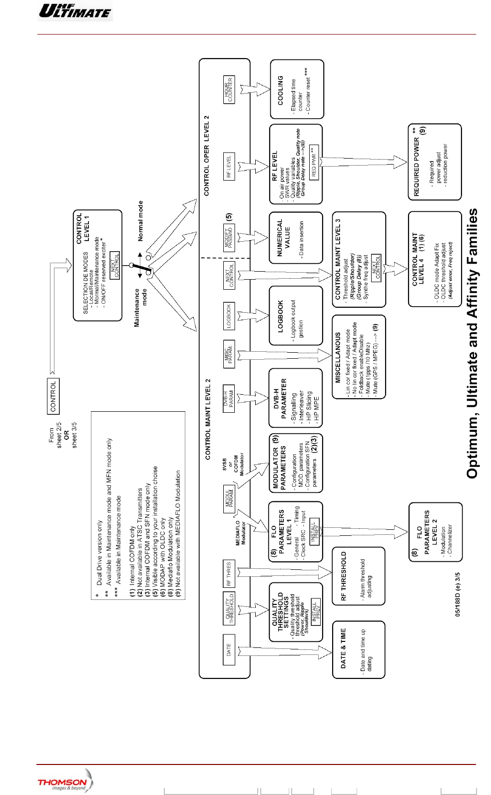
Figure 39 : Navigation in tactile screen windows (2/5)
Digital Liquid Cooled UHF
TV Equipment
Use of commands and description of indicators
9932 V2
45321648.01 108 B E Checked 181 / 192
Numéro / Number Doc. Rev. Lan
g
u. 27/06/2006 Pa
g
e
Information contained is this document is confidential, is THOMSON property and cannot be disclosed in whatever form without prior written authorization of THOMSON.
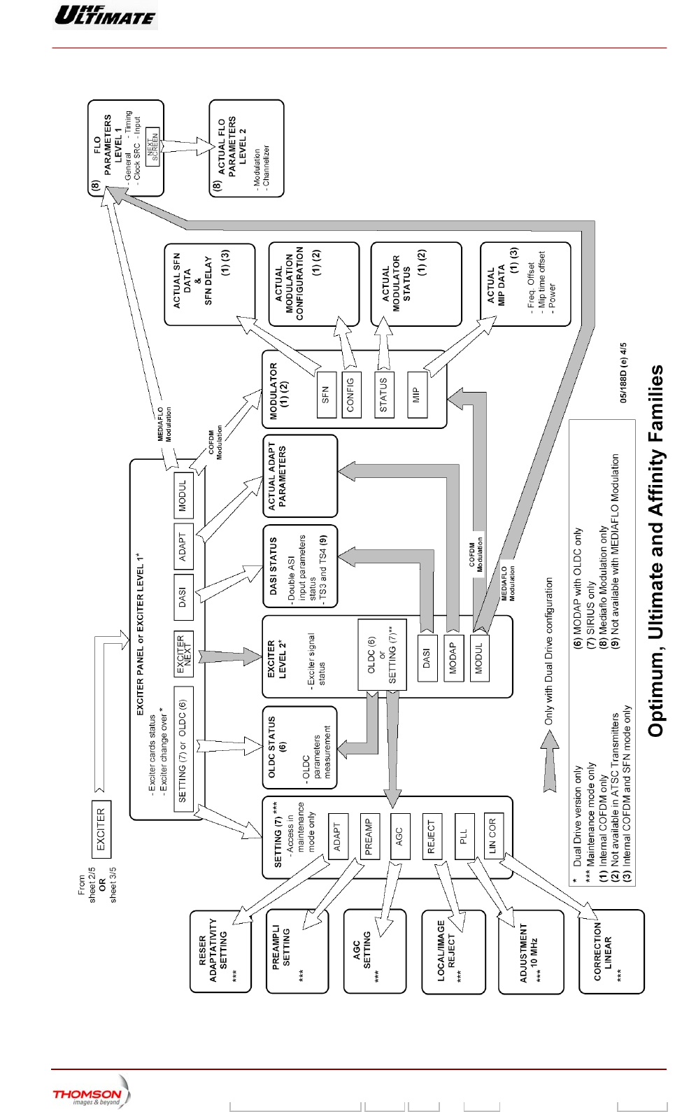
Figure 40 : Navigation in tactile screen windows (3/5)
Digital Liquid Cooled UHF
TV Equipment
Use of commands and description of indicators
9932 V2
45321648.01 108 B E Checked 182 / 192
Numéro / Number Doc. Rev. Lan
g
u. 27/06/2006 Pa
g
e
Information contained is this document is confidential, is THOMSON property and cannot be disclosed in whatever form without prior written authorization of THOMSON.
Figure 41 :: Navigation in tactile screen windows (4/5)
Digital Liquid Cooled UHF
TV Equipment
Use of commands and description of indicators
9932 V2
45321648.01 108 B E Checked 183 / 192
Numéro / Number Doc. Rev. Lan
g
u. 27/06/2006 Pa
g
e
Information contained is this document is confidential, is THOMSON property and cannot be disclosed in whatever form without prior written authorization of THOMSON.
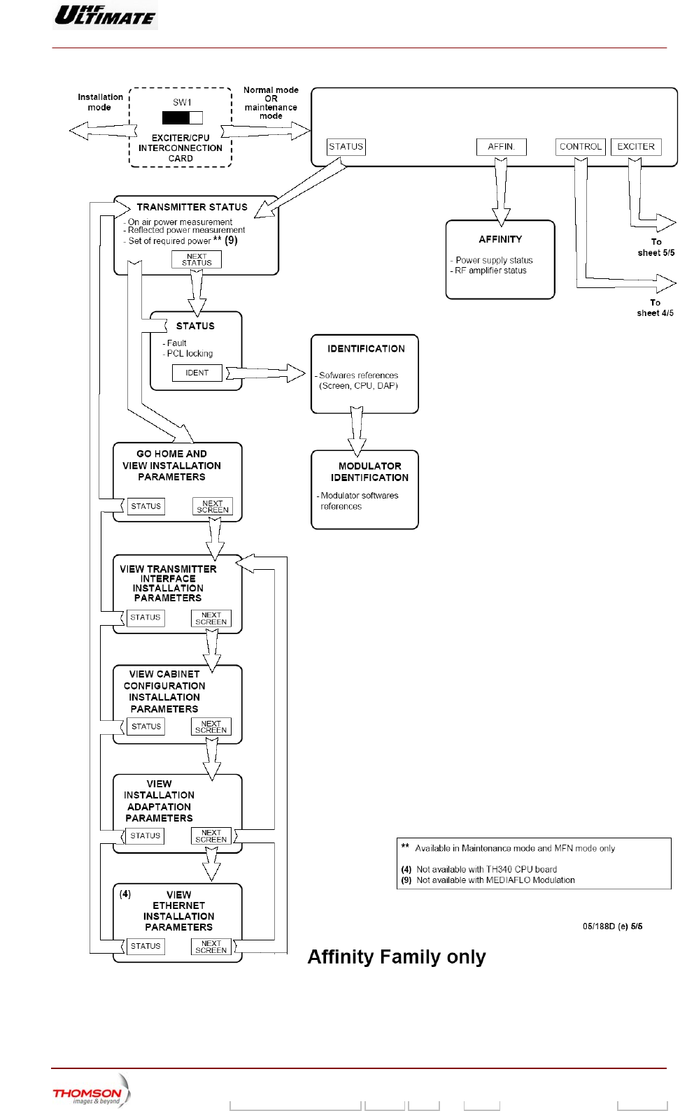
Figure 42 : Navigation in tactile screen windows (5/5)
Digital Liquid Cooled UHF
TV Equipment
Use of commands and description of indicators
9932 V2
45321648.01 108 B E Checked 184 / 192
Numéro / Number Doc. Rev. Lan
g
u. 27/06/2006 Pa
g
e
Information contained is this document is confidential, is THOMSON property and cannot be disclosed in whatever form without prior written authorization of THOMSON.
2.2. Exciter, SIRIUS
2.2.1. Front panel
A B F
CA1
E
D06/024(e-f)
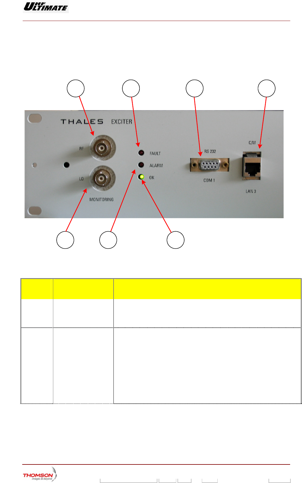
Figure 43 : Front panel (04/271(f-e))
The following appear on the SIRIUS module front panel:
DIAGRAM
REFERENCE
COMPONENT REMARKS
B Red fault LED Overall hardware fault
♦ Lit: indicates that one of the boards in the Sirius module is faulty
♦ Extinguished: normal operation
C Red ALARM LED MPEG or GPS signals at input (10 MHZ and 1 PPS)
♦ Extinguished: operational
♦ Lit: indicates that one of the input signals is absent.
In SFN mode, the inputs taken into account are:
♦ ASI 1
♦ ASI 2
♦ 10 Mhz
♦ 1 P.P.S.
Digital Liquid Cooled UHF
TV Equipment
Use of commands and description of indicators
9932 V2
45321648.01 108 B E Checked 185 / 192
Numéro / Number Doc. Rev. Lan
g
u. 27/06/2006 Pa
g
e
Information contained is this document is confidential, is THOMSON property and cannot be disclosed in whatever form without prior written authorization of THOMSON.
DIAGRAM
REFERENCE
COMPONENT REMARKS
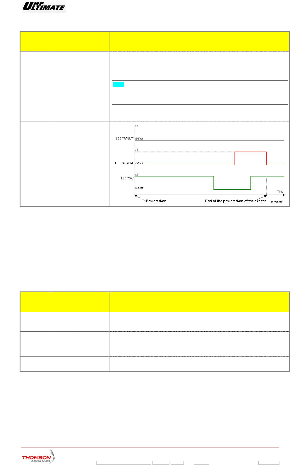
D Green OK LED This LED has two functions:
♦ Extinguished: software fault
♦ Lit: indicates that the microprocessor is operating satisfactorily (software)
Note: During the made the powered-on of exciter, the LED “OK” is lit during
approximately 15 seconds indicating the operated of power supply then, put out
(extinct) during approximately 7 seconds indicating the starting-up of the
microprocessor and to end lit. (refer to the diagram below).
2.2.1.1. Test Points
The RF output signal from the SIRIUS module can be monitored at connector A on the front of the
module.
The RF output signal from the synthesiser unit (LO) can be monitored at connector A1 on the front
panel of the SIRIUS rack.
2.2.1.2. Front panel interconnections
The following appear on the SIRIUS module front panel:
DIAGRAM
REFERENCE
COMPONENT REMARKS
E COM 1 Connector Reserved for TBM use: Serial link connection (RS232); this enables authorised
personnel to have access to the digital card micro program (Modulator). The user
must not connect anything to this connector.
F LAN Connector Reserved for TBM use: Ethernet link connection (RJ45) with digital card
(Modulator). This connection is limited to factory use and gives access to high level
functions and fault finding routines in the Sirius module (for use by a technician
using a terminal)
G PC card reader On the right hand side of the SIRIUS front panel there is a PC card reader which will
accept a memory card on which the exciter parameters can be stored (not available)
Digital Liquid Cooled UHF
TV Equipment
Use of commands and description of indicators
9932 V2
45321648.01 108 B E Checked 186 / 192
Numéro / Number Doc. Rev. Lan
g
u. 27/06/2006 Pa
g
e
Information contained is this document is confidential, is THOMSON property and cannot be disclosed in whatever form without prior written authorization of THOMSON.
2.3. Local control panel
The Local Control Panel (PCL) consists of two units:
♦ an LCD touch screen,
♦ a display circuit.
It is the principal user interface for the transmitter. It gives the
operator the facilities to display the various status conditions of the
transmitter and its main sub-units.
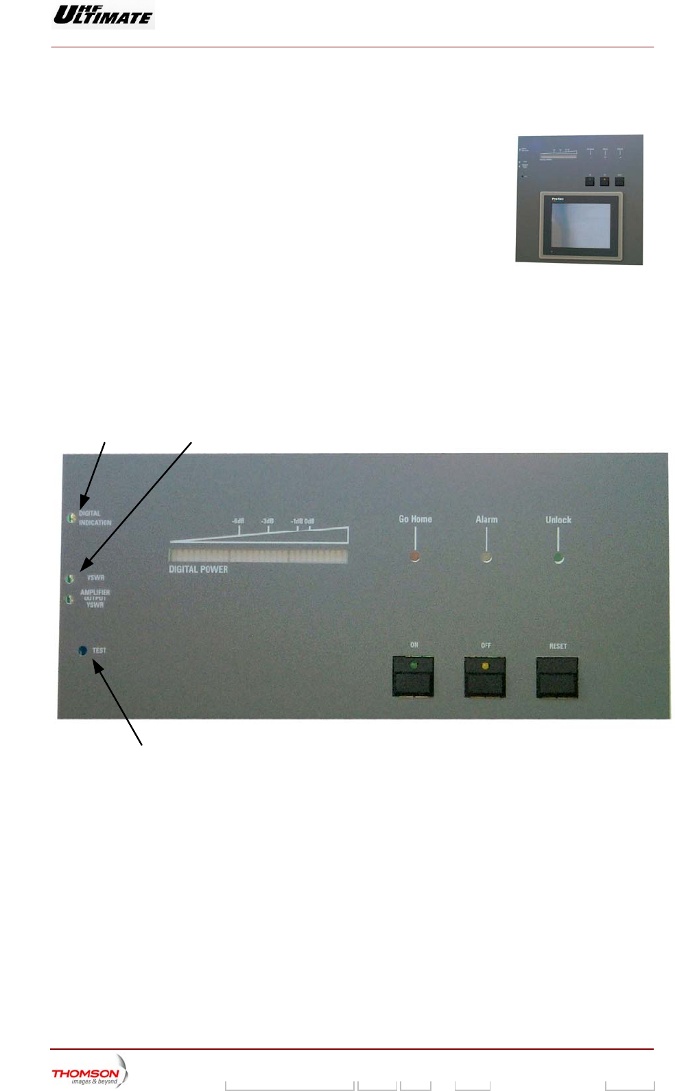
2.3.1. Indicator lamps and message displays
There are no status indicator lamps to indicate the status conditions of the display card. The indicator
lamps on the front of the PCL indicate the overall status of the transmitter.
2.3.2. Adjustment controls
R435
TEST
R475
The sensitivity controls on the front of the PCL are used to set the parameters which are displayed by
the bar graph on the PCL and in the "RF REFLECTED LEVEL" and "RF LEVEL" windows; these
adjustments set the input signals and are as follows :
♦ R435 “POWER INDICATION” : sensitivity control for output power indication,
♦ R475 “ANTENNA VSWR” : sensitivity control for antenna SWR indication.
The output power level is displayed on the bargraph.
Return SWR values are displayed on the "RF REFLECTED LEVEL" window.
2.3.3. Test points
Pressing on the "TEST" button on the front panel of the PCL with a pointed object will check that the
indicator lamps and bargraph LED’s are working properly.
Digital Liquid Cooled UHF
TV Equipment
Use of commands and description of indicators
9932 V2
45321648.01 108 B E Checked 187 / 192
Numéro / Number Doc. Rev. Lan
g
u. 27/06/2006 Pa
g
e
Information contained is this document is confidential, is THOMSON property and cannot be disclosed in whatever form without prior written authorization of THOMSON.
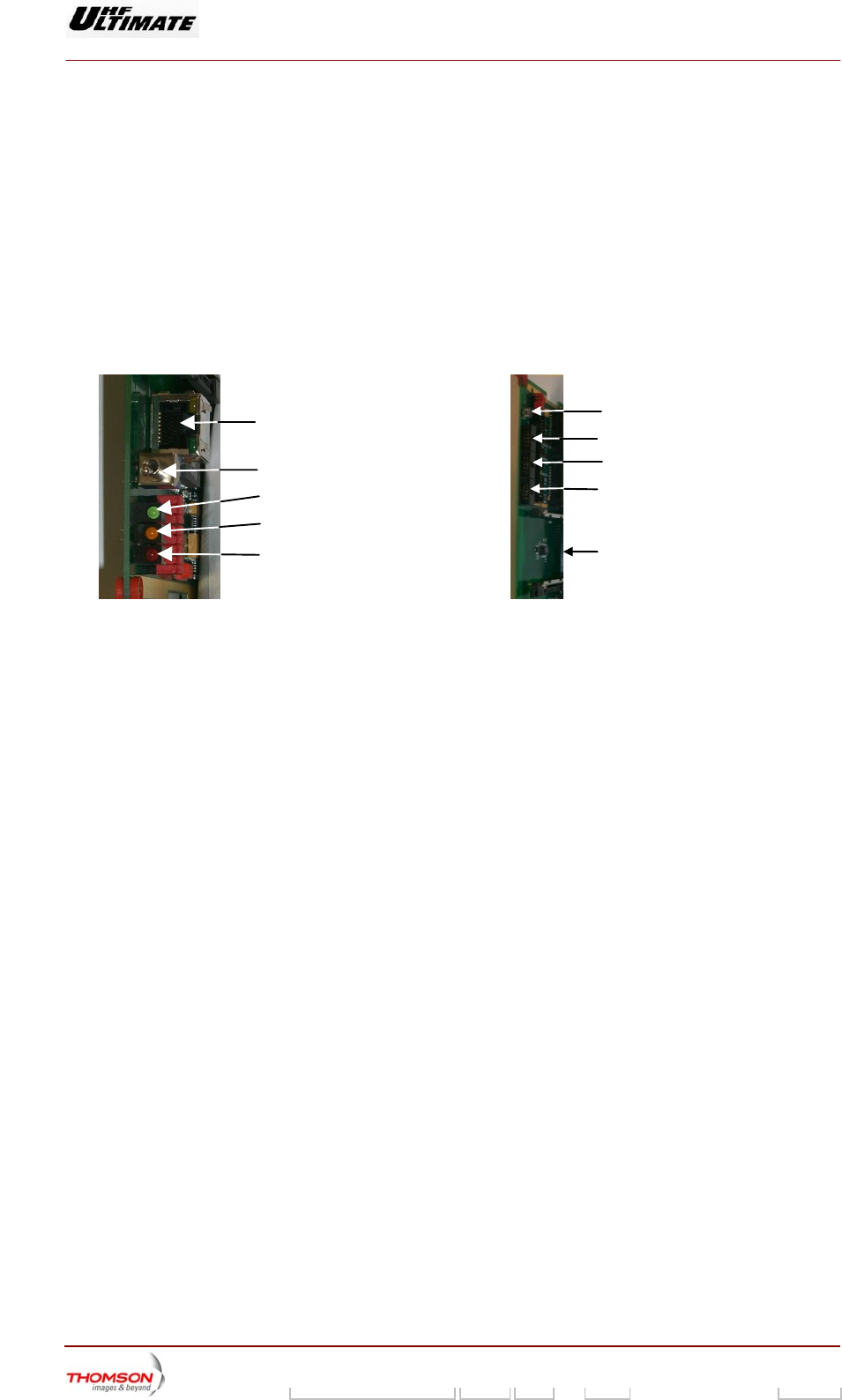
2.4. TH860 CPU Card
2.4.1. Indicator lamps and message displays
The Central Processing Unit card has the following on its front panel :
♦ a green indicator lamp : when this flashes the memory access is operating satisfactorily,
♦ an orange/yellow indicator lamp: when this is lit up the CPU card is powered,
♦ an red indicator lamp: when this is lit up CPU board is not operating properly (light up a short time
during CPU start up).
yellow LED
red LED
Green LED
switch not used
Ethernet connection
RJ45
P1
Location for PCMCIA card
P2
P3
CPU Reset
2.4.2. Controls
The switch on the CPU front panel is not used.
Digital Liquid Cooled UHF
TV Equipment
Use of commands and description of indicators
9932 V2
45321648.01 108 B E Checked 188 / 192
Numéro / Number Doc. Rev. Lan
g
u. 27/06/2006 Pa
g
e
Information contained is this document is confidential, is THOMSON property and cannot be disclosed in whatever form without prior written authorization of THOMSON.
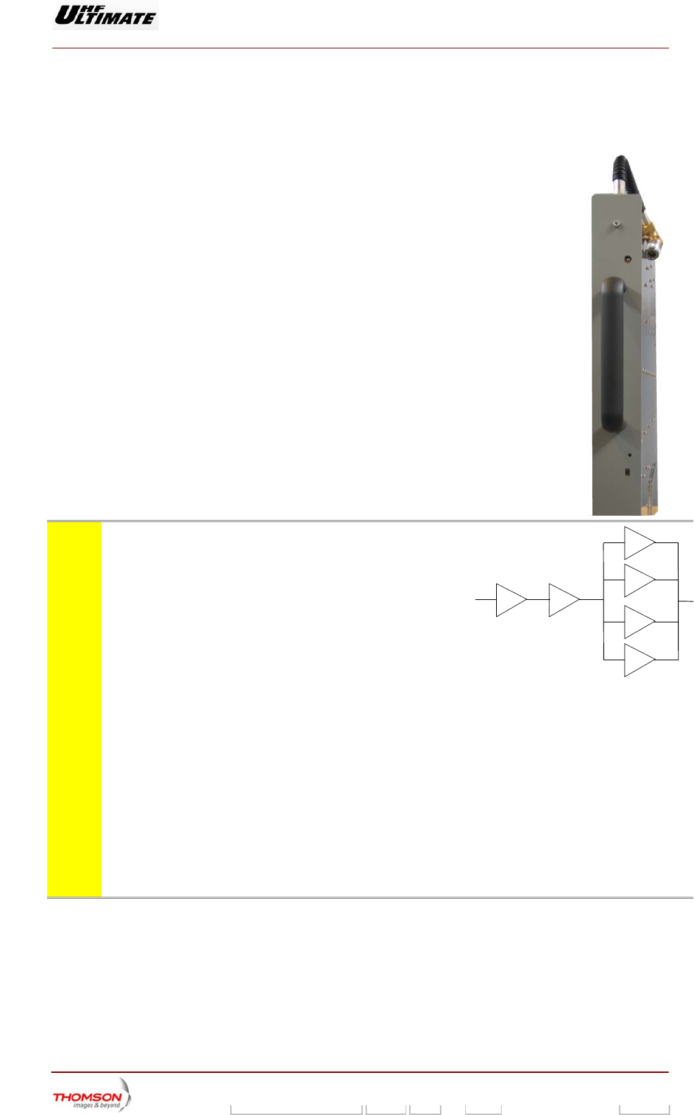
2.5. RF amplifier unit
2.5.1. Indicator lamps and message displays
♦ A LED indicator on the front panel of the amplifier card indicates the status
of the transmitter as follows :
• LED extinguished : voltage supply has failed or is ≤ 24V,
• green LED : amplifier voltage supply is present and it is working
satisfactorily,
• red LED :
- transistor failure as follows :
I < 2.4 A for a group of 4 power transistors with polarisation (P input >
-4dBm)
- overdrive (over current or power protection system activated and fault
stored : 45 A for 4 double transistors),
- P input > -4 to -3dBm and P output <250W
- SWR protection system activated and fault stored (≥ 2 ),
- thermal protection system activated and fault stored (air input
temperature ≥ 60°C),
• orange LED : internal power supply absent in the protection system card.
NOTE: The PCL «AMPLIFIERS» window displays the status
conditions of a power amplifier as follows :
• transistor current values:
- T1 : amplifier modules 1 and 2,
- T2 : amplifier modules 3 and 4,
- T3 : amplifier modules 5 and 6,
- T4 : amplifier modules 7 and 8,
- T5 : transistors in class AB drive amplifier,
- T6 : transistors in class A preamplifier,
• ON,
• general fault,
• SWR fault,
• overdrive fault,
• internal temperature fault,
• presence/absence.
T1
T2
T3
T4
T5T6

Digital Liquid Cooled UHF
TV Equipment
Use of commands and description of indicators
9932 V2
45321648.01 108 B E Checked 189 / 192
Numéro / Number Doc. Rev. Lan
g
u. 27/06/2006 Pa
g
e
Information contained is this document is confidential, is THOMSON property and cannot be disclosed in whatever form without prior written authorization of THOMSON.
2.5.2. Test points
Connector J1 on the front of the panel provides a test monitoring
feed of the amplifier RF output signal.
2.5.3. Adjustment controls
There is a potentiometer control (R164) on the front panel of each
RF amplifier module which is used to set the AGC voltage of each
power amplifier to the same value.
Digital Liquid Cooled UHF
TV Equipment
Use of commands and description of indicators
9932 V2
45321648.01 108 B E Checked 190 / 192
Numéro / Number Doc. Rev. Lan
g
u. 27/06/2006 Pa
g
e
Information contained is this document is confidential, is THOMSON property and cannot be disclosed in whatever form without prior written authorization of THOMSON.
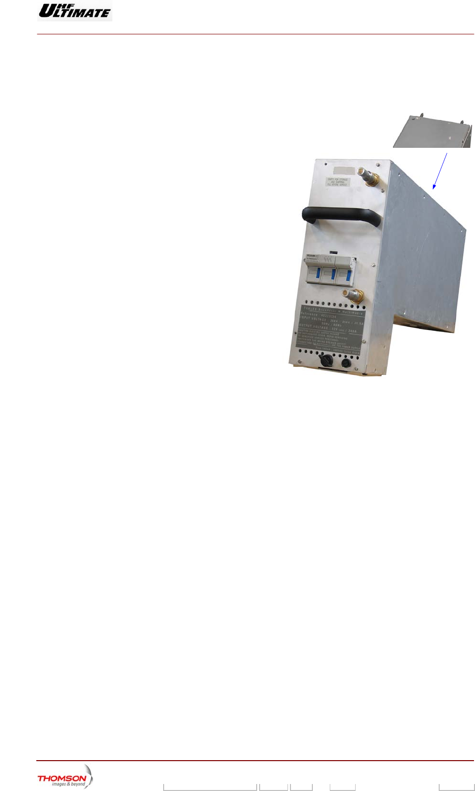
2.6. Power supply unit
2.6.1. Using the commands
The amplifier power supplies are fed via a switch
fuse isolator for protection of the power supply,
accessible to the operator on the front panel.
2.6.2. Indicator lamps and message
displays
A green LED on the upper panel indicates the
status of the power supply as follows :
♦ when lit up it indicates that there is an output
DC voltage and that the power supply is in
operation,
Green Led
output voltage
present
06/086(e)
♦ when extinguished it indicates that there is no output DC voltage and that the power supply is shut
down or faulty.
Note : The «POWER SUPPLY» window which can be displayed on the PCL displays the status
conditions for the power supplies in a bay as follows :
♦ POWERED OFF : power supply shut down but fault-free,
♦ POWERED ON : power supply in operation and fault-free,
♦ FAULT : mains input failure; this indication is independent of the power
supply operational status (on or off),
♦ MISSING : power supply absent,
♦ BREAKER OFF : fused isolator open circuited,
♦ MAINS FAULT : one of the mains fuses F2 to F4 has failed,
♦ UNKNOW : internal power supply fault in the multiplex card.
2.6.3. Test points
The amplifier power supply has no test points.
2.6.4. Adjustment controls
The amplifier power supply has no adjustment controls available to the operator.

Digital Liquid Cooled UHF
TV Equipment
Use of commands and description of indicators
9932 V2
45321648.01 108 B E Checked 191 / 192
Numéro / Number Doc. Rev. Lan
g
u. 27/06/2006 Pa
g
e
Information contained is this document is confidential, is THOMSON property and cannot be disclosed in whatever form without prior written authorization of THOMSON.
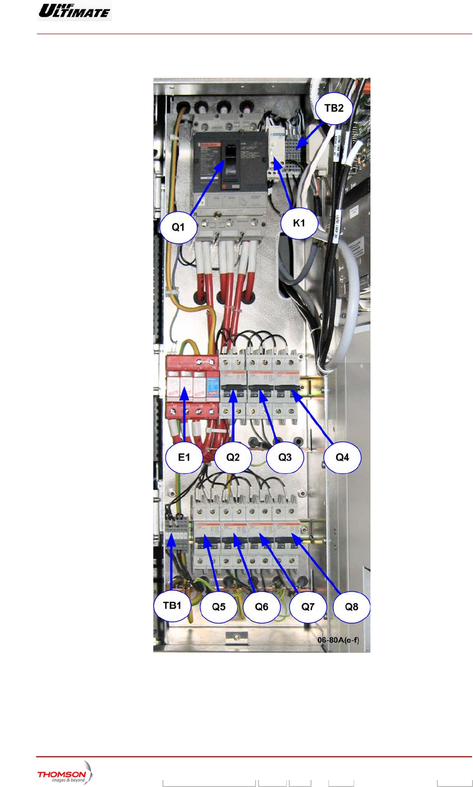
2.7. 860 Cabinet Mains distribution
The Mains Distribution Panel provide selective protection for the installation so that only the protective
device immediately ahead of the fault will be activated :
• Circuit breaker Q6 : protects the mains feeds of the very low voltage power supply for the
Control Processor Unit via the management rack,
• Circuit breaker Q7 : not used,
• Circuit breaker Q8 : protects the mains feeds of external exhaust fan EV3.
• Circuit breaker Q5 : protects the mains feeds of an uninterruptible power supply (UPS) - option,
This configuration, with an uninterruptible power supply (UPS) is an option. Without this
element, Q5 is not used and the mains come from “emergency mains input” (see “LV
distribution” drawing for TB1 terminal block configuration )
• Circuit breaker Q2 : protects the mains feeds of Sirius 1,
• Circuit breaker Q3 : protects the mains feeds of Sirius 2,
• Circuit breaker Q4 : protects the mains feeds of the very low voltage power supply for the
screen of the control panel via the management rack
2.7.1. Indicator lamps and message displays
♦ An orange indicator lamp on the mains monitoring relay K1 gives further information on the
incoming main supply as follows:
• Lit up : OK,
• Extinguished: absence or inversion of phases.
♦ E1 includes 4 surge arrestors “over voltage protection” ( 3 between Phases and Ground , the 4 th.
one between Neutral and Ground .When one surge arrestor is damaged, the light on the
corresponding arrestor is on : the plug-in module has to be replaced .
2.7.2. Test points and adjustment controls
The front panel of the Mains Distribution Panel does not have any test points or adjustment controls,
which can be used by the operator.
Digital Liquid Cooled UHF
TV Equipment
Use of commands and description of indicators
9932 V2
45321648.01 108 B E Checked 192 / 192
Numéro / Number Doc. Rev. Lan
g
u. 27/06/2006 Pa
g
e
Information contained is this document is confidential, is THOMSON property and cannot be disclosed in whatever form without prior written authorization of THOMSON.
Figure 44 : Localisation of the main items of the Energy plate