HAICOM Electronics HI-601VT GPS/GSM Tracking Device - Decoder Unit User Manual Manual 8
HAICOM Electronics Corp. GPS/GSM Tracking Device - Decoder Unit Manual 8
Contents
Manual 8
Feature
SIM interface
Audio interfaces
Audio features
Two serial interfaces:
ASC0,ASC1
SIM Application
Toolkit
Ringing tones
Real time clock
Timer function
Support of TTY/CTM
Firmware upgrade
Implementation
•Supported SIM card: 3V
•External SIM card reader has to be connected via
interface connector
Two analog audio interfaces, one digital audio
interface(DAI)
Speech code modes:
•Half Rate (ETS 06.20)
•Full Rate (ETS 06.10)
•Enhanced Full Rate (ETS 06.50 / 06.60 / 06.80)
•Adaptive Multi Rate (AMR)
Handsfree operation
•Echo cancellation
•Noise reduction
•2.65V level, bi-directional bus for AT commands and
data
•ASC0 - full- featured 8-wire serial interface. Supports
RTS0/CTS0 hardware handshake and software
XON/XOFF flow control. Multiplex ability according to
GSM 07.10 Multiplexer Protocol.
•ASC1 - 4-wire serial interface. Supports RTS1/CTS1
hardware handshake and software XON/XOFF flow
control.
•Baud rate: 300bps… 230kbps on ASC0 and ASC1
•Autobauding (on ASC0 only) detects 1200, 2400, 4800,
9600, 19200, 38400, 57600, 115200, 230400 bps
SIM Application Toolkit Supports SAT class3, GSM 11.14
Release 98, support of letter class ”c”
Offers a choice of 7 different ringing tones / melodies,
easily selectable with AT command
Implemented
Programmable via AT command
To benefit from TTY communication via GSM, CTM
equipment can be connected to one of the three audio
interfaces.
Firmware upgradable over serial interface and SIM
interface
27
27
HI-601VT

HI-601VT Decoder
How to Use:
A.Connect the inclusive phone jack/PSII to mini1394 Y cable
to the decoder: Mini1394 connector to the side of the
decoder, phone jack to the phone jack outlet)
B.As soon as turn on the power switch, the red LED light start
blinking once per second. The updated coordinates will be
sent out from “mini-1394 output” and “Bluetooth output”
each second.
PS. The data format is 4800, 8, N, 1 and computer will take the
RS232 data from COM 1, COM2 or other com port.
C.Start mapping software and activate the GPS signal
receiving. The most update location (or the last location) will
be shown on the mapping software.
D.The orange LED light (GPS in 3D fixed) followed by the red
light meaning the data is valid and is the real time location
coordinate. The status also means that the car or the person
should be in outdoor and the GPS receiver able to gets and
lock more than 4 satellites. If the yellow light not lighted
meaning the GPS data is not the real time coordinate (could
be the old location coordinate) The status also means that
the car or the person should be indoor and the GPS receiver
unable to gets and lock more than 4 satellites.
28
28
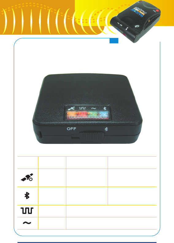
Decoder LED indicator
Symbol LED Color
Orange
Bluetooth
Red
Green
Stay on
GPS data valid
(3D fixed)
Bluetooth
Connected
Decoding (4 seconds interval)
Receiving data
Blinking
GPS data not valid
Bluetooth
no connected
29
29
HI-601VT