LINKSYS WT54GV40 802.11G Broadband Router with SpeedBooster/Switch User Manual Book
LINKSYS LLC 802.11G Broadband Router with SpeedBooster/Switch Book
LINKSYS >
Contents
- 1. Users Manual 1
- 2. Users Manual 2
- 3. Users Manual 3
- 4. Users Manual 4
- 5. Users Manual 5
- 6. Users Manual 6
- 7. Users Manual 7
- 8. Users Manual 8
- 9. Users Manual 9
- 10. Users Manual 10
- 11. Users Manual 11
- 12. Users Manual 12
- 13. Users Manual 13
- 14. Users Manual 14
- 15. Users Manual 15
- 16. Users Manual 16
- 17. Users Manual 17
- 18. Users Manual 18
Users Manual 2

4
Chapter 2: Planning Your Wireless Network
Network Topology
Wireless-G Broadband Router
Chapter 2: Planning Your Wireless Network
Network Topology
A wireless local area network (WLAN) is exactly like a regular local area network (LAN), except that each
computer in the WLAN uses a wireless device to connect to the network. Computers in a WLAN share the same
frequency channel and SSID, which is an identification name shared by the wireless devices belonging to the
same wireless network.
Ad-Hoc versus Infrastructure Mode
Unlike wired networks, wireless networks have two different modes in which they may be set up: infrastructure
and ad-hoc. An infrastructure configuration is a WLAN and wired LAN communicating to each other through an
access point. An ad-hoc configuration is wireless-equipped computers communicating directly with each other.
Choosing between these two modes depends on whether or not the wireless network needs to share data or
peripherals with a wired network or not.
If the computers on the wireless network need to be accessible by a wired network or need to share a peripheral,
such as a printer, with the wired network computers, the wireless network should be set up in Infrastructure
mode. The basis of Infrastructure mode centers around a wireless router or an access point, such as the
Wireless-G Broadband Router, which serves as the main point of communications in a wireless network. The
Router transmits data to PCs equipped with wireless network adapters, which can roam within a certain radial
range of the Router. You can arrange the Router and multiple access points to work in succession to extend the
roaming range, and you can set up your wireless network to communicate with your Ethernet hardware as well.
If the wireless network is relatively small and needs to share resources only with the other computers on the
wireless network, then the Ad-Hoc mode can be used. Ad-Hoc mode allows computers equipped with wireless
transmitters and receivers to communicate directly with each other, eliminating the need for a wireless router or
access point. The drawback of this mode is that in Ad-Hoc mode, wireless-equipped computers are not able to
communicate with computers on a wired network. And, of course, communication between the wireless-
equipped computers is limited by the distance and interference directly between them.
Network Layout
The Wireless-G Broadband Router has been specifically designed for use with both your 802.11b and 802.11g
products. Now, products using these standards can communicate with each other.
infrastructure: a wireless network that is bridged
to a wired network via an access point.
ssid (service set identifier): your wireless network’s name.
ad-hoc: a group of wireless devices
communicating directly to each other (peer-to-
peer) without the use of an access point.

5
Chapter 2: Planning Your Wireless Network
Network Layout
Wireless-G Broadband Router
The Wireless-G Broadband Router is compatible with all 802.11b and 802.11g adapters, such as the Notebook
Adapters (WPC54G, WPC11) for your laptop computers, PCI Adapter (WMP54G, WMP11) for your desktop PC, and
USB Adapter (WUSB54G, WUSB11) when you want to enjoy USB connectivity. The Broadband Router will also
communicate with the Wireless PrintServer (WPS54G) and Wireless Ethernet Bridges (WET54G, WET11).
When you wish to connect your wireless network with your wired network, you can use the Wireless-G
Broadband Router’s four LAN ports. To add more ports, any of the Wireless-G Broadband Router's LAN ports can
be connected to any of Linksys's switches (such as the SD205 or SD208).
With these, and many other, Linksys products, your networking options are limitless. Go to the Linksys website at
www.linksys.com for more information about products that work with the Wireless-G Broadband Router.
6
Chapter 3: Getting to Know the Wireless-G Broadband Router
The Back Panel
Wireless-G Broadband Router
Chapter 3: Getting to Know the Wireless-G Broadband Router
The Back Panel
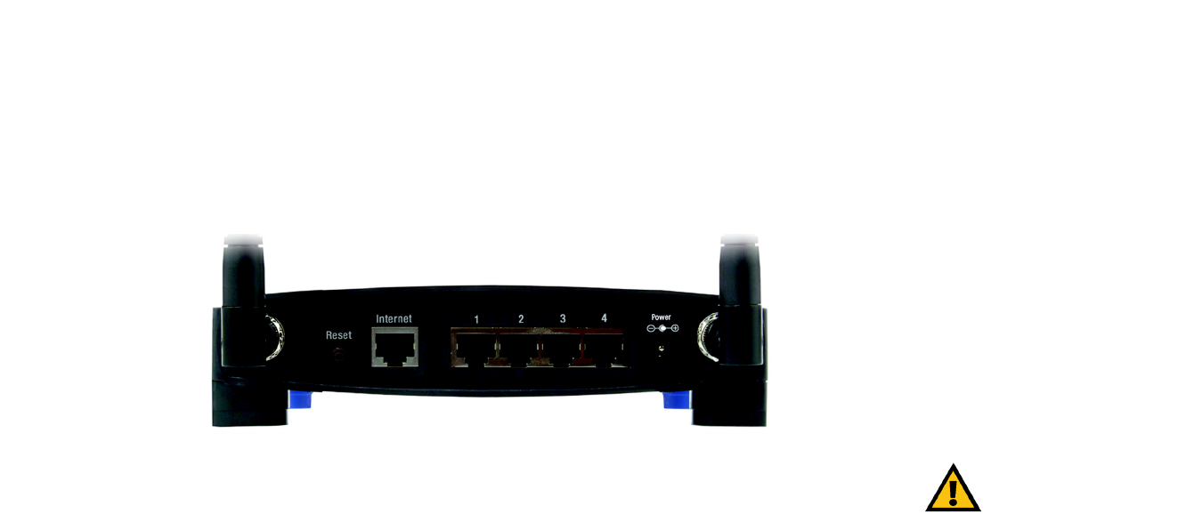
The Router's ports, where the cables are connected, are located on the back panel.
Reset Button There are two ways to reset the Router's factory defaults. Either press the Reset Button, for
approximately five seconds, or restore the defaults from the Administration tab - Factory
Defaults in the Router's Web-based Utility.
Internet The Internet port is where you will connect your broadband Internet connection.
1, 2, 3, 4 These ports (1, 2, 3, 4) connect the Router to your networked PCs and other Ethernet network
devices.
Power The Power port is where you will connect the power adapter.
IMPORTANT: Resetting the Router will erase
all of your settings (Internet connection,
wireless security, and other settings) and
replace them with the factory defaults. Do not
reset the Router if you want to retain these
settings.
Figure 3-1: The Router’s Back Panel
7
Chapter 3: Getting to Know the Wireless-G Broadband Router
The Front Panel
Wireless-G Broadband Router
The Front Panel
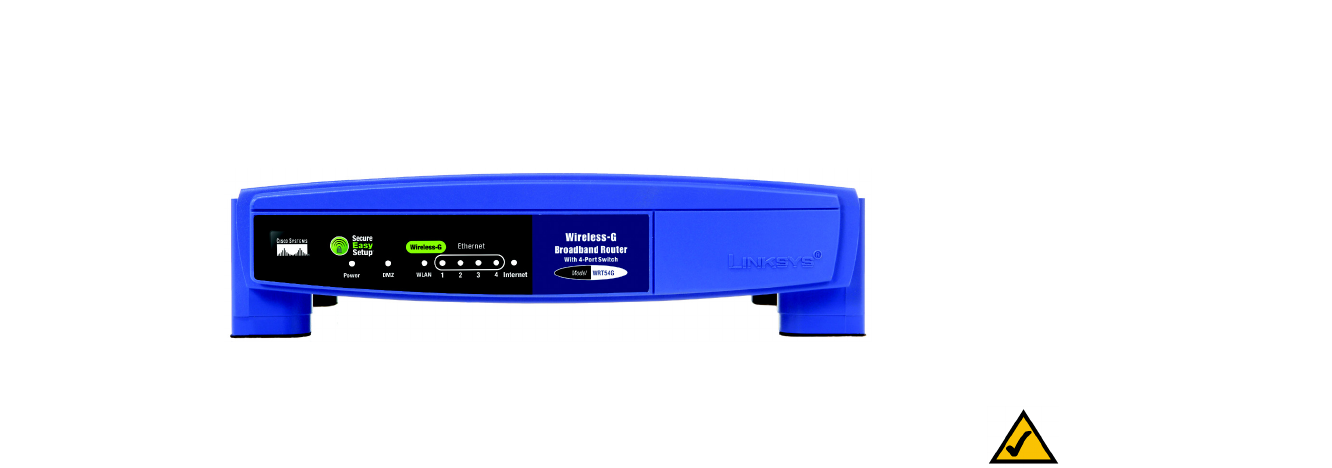
The Router’s SecureEasySetup button (the Cisco logo) and LEDs are located on the front panel.
(Cisco logo) Orange/White. The Cisco logo is the Router’s SecureEasySetup button. It lights up and will stay
orange when the Router is powered on. The color orange indicates that the Router is not using
the SecureEasySetup feature, while the color white indicates that the Router is using the
SecureEasySetup feature. When the Router enters SecureEasySetup mode, the Cisco logo will
turn white and start flashing. After the Router has generated the SSID and WPA-PSK (also
called WPA-Personal) key, the Cisco logo will stop flashing and stay white.
To clear the SSID and WPA-PSK key, press and hold down the Cisco logo for five seconds. The
Cisco logo will flash slowly as the Router resets itself. The Cisco logo will turn orange to
indicate a successful reset.
Power Green. The Power LED lights up and will stay on while the Router is powered on. When the
Router goes through its self-diagnostic mode during every boot-up, this LED will flash. When
the diagnostic is complete, the LED will be solidly lit.
DMZ Green. The DMZ LED indicates when the DMZ function is being used. This LED will remain lit
as long as DMZ is enabled.
WLAN Green. The WLAN LED lights up whenever there is a successful wireless connection. If the LED
is flashing, the Router is actively sending or receiving data over the network.
1, 2, 3, 4 Green. These numbered LEDs, corresponding with the numbered ports on the Router’s back
panel, serve two purposes. If the LED is continuously lit, the Router is successfully connected
to a device through that port. A flashing LED indicates network activity over that port.
Internet Green. The Internet LED lights up when there is a connection made through the Internet port.
Figure 3-2: The Router’s Front Panel
NOTE: SecureEasySetup is a feature that makes it
easy to set up your wireless network. If you have
SecureEasySetup devices, run the Router’s Setup
Wizard CD-ROM and follow the on-screen
instructions to use SecureEasySetup.
8
Chapter 4: Connecting the Wireless-G Broadband Router
Overview
Wireless-G Broadband Router
Chapter 4: Connecting the Wireless-G Broadband Router
Overview
This chapter includes two sets of instructions. If the Wireless-G Broadband Router will be the only router in your
network, follow the instructions in “Hardware Installation for Connection to Your Broadband Modem.” If you want
to install the Wireless-G Broadband Router behind another router in your network, then follow the instructions in
“Hardware Installation for Connection to Another Router.”
Hardware Installation for Connection to Your Broadband Modem
1. Power down your network devices.
2. Locate an optimum location for the Router. The best place for the Router is usually at the center of your
wireless network, with line of sight to all of your mobile stations.
3. Fix the direction of the antennas. Try to place the Router in a position that will best cover your wireless
network. Normally, the higher you place the antenna, the better the performance will be.
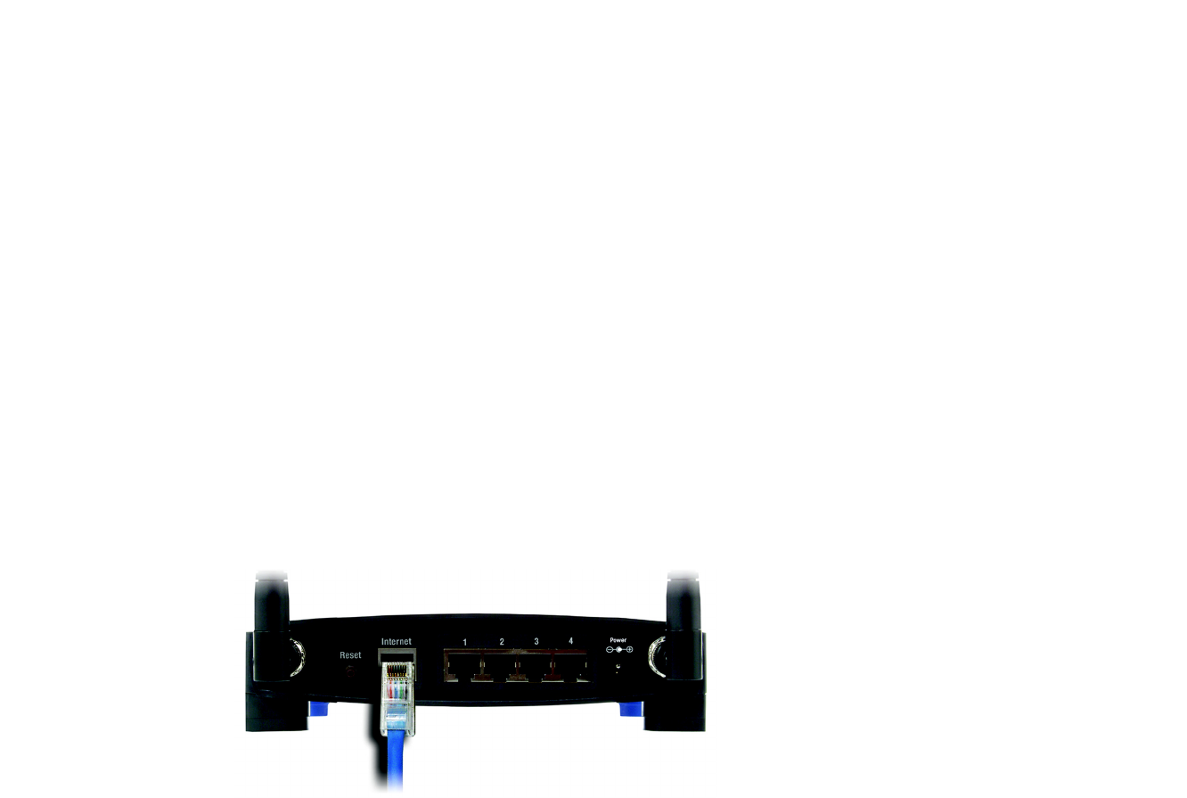
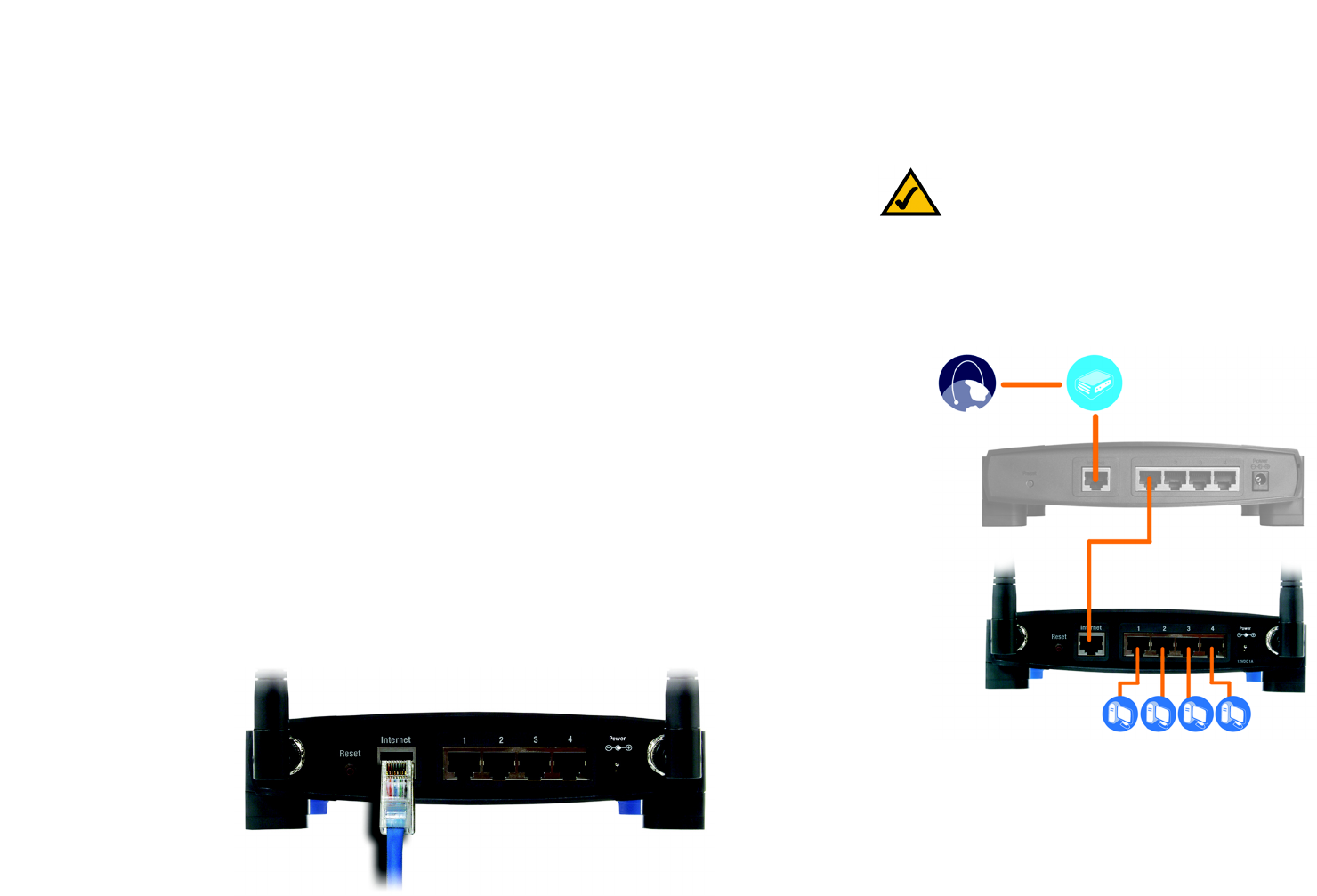
4. Connect a standard Ethernet network cable to the Router’s Internet port. Then, connect the other end of the
Ethernet cable to your cable or DSL broadband modem.
Figure 4-1: Connecting Your Internet Connection
9
Chapter 4: Connecting the Wireless-G Broadband Router
Hardware Installation for Connection to Your Broadband Modem
Wireless-G Broadband Router
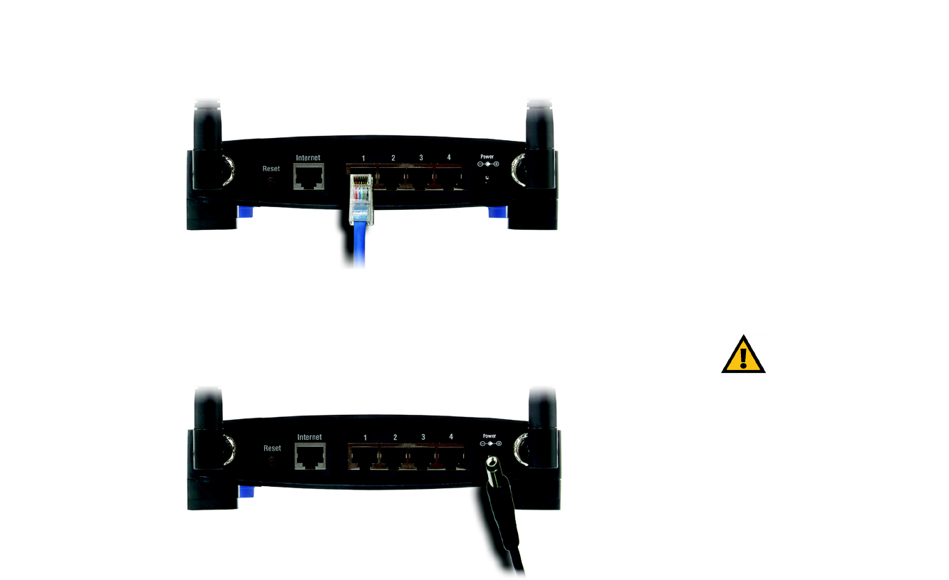
5. Connect your network PCs or Ethernet devices to the Router’s numbered ports using standard Ethernet
network cabling.
6. Connect the AC power adapter to the Router's Power port and the other end into an electrical outlet. Only use
the power adapter supplied with the Router. Use of a different adapter may result in product damage.
Now that the hardware installation is complete, proceed to “Chapter 5: Setting up the Wireless-G
Broadband Router,” for directions on how to configure the Router.
Figure 4-2: Connecting Your Network Devices
Figure 4-3: Connecting the Power
IMPORTANT: Make sure you use the power
adapter that is supplied with the Router. Use of a
different power adapter could damage the Router.
10
Chapter 4: Connecting the Wireless-G Broadband Router
Hardware Installation for Connection to Another Router
Wireless-G Broadband Router
Hardware Installation for Connection to Another Router
Before you install the Router, you must change the default IP address of the other router. This is mandatory
because both routers may be set to the same IP address by default. If you do not change the other router’s default
IP address, then you may not be able to set up the Router.
First, make sure the Router is NOT connected to your network. Then follow these instructions:
1. To access the other router’s Web-based Utility, launch Internet Explorer or Netscape Navigator, and enter the
other router’s default IP address, 192.168.1.1, in the Address field. Then press Enter.
2. A password request page will appear. Leave the User Name field blank. In the Password field, enter the
password you have set (the default password is admin). Then click the OK button.
3. The first screen that appears will display the Setup tab. In the Network Setup section, there is a setting called
Local IP Address, which is set to 192.168.1.1. Change this to 192.168.2.1.
4. Click the Save Settings button to save your change, and then exit the Web-based Utility.
5. Power down your network devices. Now you will begin the hardware installation of Router.
6. Locate an optimum location for the Router. The best place for the Router is usually at the center of your
wireless network, with line of sight to all of your mobile stations.
7. Fix the direction of the antennas. Try to place the Router in a position that will best cover your wireless
network. Normally, the higher you place the antenna, the better the performance will be.
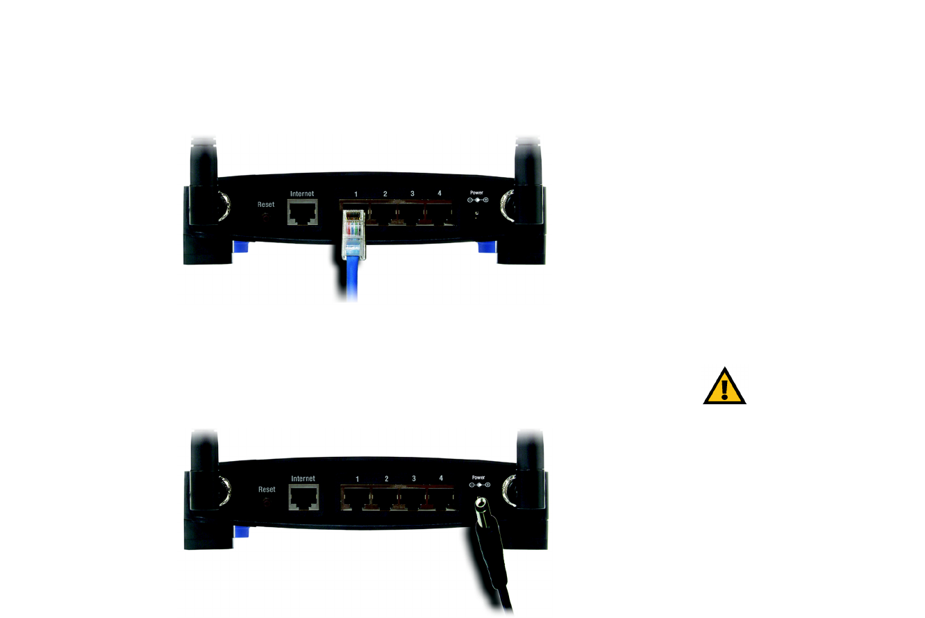
8. Connect a standard Ethernet network cable to the Router’s Internet port. Then, connect the other end of the
Ethernet cable to one of the numbered Ethernet ports on your other router.
Figure 4-4: Diagram for Connection to Another Router
NOTE: Steps 1-4 are instructions for a typical
Linksys router; however, if you are using a non-
Linksys router, refer to the other router’s
documentation for instructions on how to change its
local IP address to 192.168.2.1.
Internet Broadband
Modem
Router
Wireless-G
Broadband
Router
Figure 4-5: Connecting Another Router
Multiple PCs
11
Chapter 4: Connecting the Wireless-G Broadband Router
Hardware Installation for Connection to Another Router
Wireless-G Broadband Router
9. Decide which network computers or Ethernet devices you want to connect to the Router.
Disconnect the selected computers or devices from the other router, and then connect them to the Router’s
numbered ports using standard Ethernet network cabling.
10. Connect the AC power adapter to the Router's Power port and the other end into an electrical outlet. Only use
the power adapter supplied with the Router. Use of a different adapter may result in product damage.
Now that the hardware installation is complete, proceed to “Chapter 5: Setting up the Wireless-G
Broadband Router,” for directions on how to configure the Router.
IMPORTANT: Make sure you use the power
adapter that is supplied with the Router. Use of a
different power adapter could damage the Router.
Figure 4-6: Connecting Your Network Devices
Figure 4-7: Connecting the Power

12
Chapter 5: Setting up the Wireless-G Broadband Router
Overview
Wireless-G Broadband Router
Chapter 5: Setting up the Wireless-G Broadband Router
Overview
The Wireless-G Broadband Router Setup Wizard will guide you through the installation procedure. It will go
through the instructions for configuring the Router’s network and wireless settings.
Using the Setup Wizard
1. Insert the Setup Wizard CD-ROM into your CD-ROM drive. The Setup Wizard should run automatically, and
the Welcome screen should appear. If it does not, click the Start button and choose Run. In the field that
appears, enter D:\setup.exe (if “D” is the letter of your CD-ROM drive).
2. The Setup Wizard will automatically detect the language setting of your PC. On the initial Welcome screen,
click the Next button if you want to proceed with the Setup Wizard using the current language. If you want to
use a different language, select the appropriate language, and then click the Next button.
3. On the following Welcome screen, click the Click Here to Start button if this is the first time you are running
the Setup Wizard. These are your other choices:
Wireless Setup - If you have a computer displaying the SecureEasySetup logo, then click Wireless Setup
and proceed to the section at the end of this chapter, “Using SecureEasySetup to Configure Your Notebook.”
Norton Internet Security - Click the Norton Internet Security button to install the Norton Internet Security
software program.
User Guide - Click the User Guide button to open the PDF file of this User Guide.
Exit - Click the Exit button to exit the Setup Wizard.
Figure 5-1: Setup Wizard’s Welcome - Language
Selection Screen
Figure 5-2: Setup Wizard’s Welcome - Start
Wizard Screen
NOTE: SecureEasySetup uses WPA-Personal encryption. If your current wireless devices do not
support WPA-Personal security, then you cannot use SecureEasySetup on your network. You will
need to manually configure your network security using the encryption supported by your
existing devices.

13
Chapter 5: Setting up the Wireless-G Broadband Router
Using the Setup Wizard
Wireless-G Broadband Router
4. After reading the License Agreement, click the Next button if you accept, or click the Cancel button to end
the installation.
5. The Setup Wizard will ask you to disconnect your broadband modem from your PC. After you have done so,
click the Next button.
Figure 5-3: Setup Wizard’s License Agreement Screen
Figure 5-4: Setup Wizard’s Disconnect the Modem from
the PC Screen