TOSHIBA TEC Singapore S-0601 Dot Printer User Manual 10
TOSHIBA TEC Singapore Pte Ltd Dot Printer Users Manual 10
Contents
- 1. Users Manual 1
- 2. Users Manual 2
- 3. Users Manual 3
- 4. Users Manual 4
- 5. Users Manual 5
- 6. Users Manual 6
- 7. Users Manual 7
- 8. Users Manual 8
- 9. Users Manual 9
- 10. Users Manual 10
- 11. Users Manual 11
- 12. Users Manual 12
- 13. Users Manual 13
- 14. Users Manual 14
- 15. Users Manual 15
- 16. Users Manual 16
- 17. Users Manual 17
- 18. Users Manual 18
Users Manual 10
4
Using Special Mode
Your Mobile Printer has two operation modes:
– The Normal mode is used for daily operations like paper handling and printing as
explained in Chapter 2, “Paper Handling," and Chapter 3, “Printing.”
– The Special mode is used to change the printer settings.
The following table summarizes the purpose of each function.
Special Mode Functions
Function
Purpose
Setup Mode
Change the Printer setting
Print Configuration Print the Printer Configuration
To check your settings by printing a list of all the
printer’s currently selected values.
Printing Test Run the printing test
Hex Dump Mode Hex-dump allows you to determine whether the
computer is sending the correct commands to the
printer
Printing Alignment
Adjustment
Perform adjustment Bi-directional alignment
Top Adjustment Change the top-of-form fine adjustment
Setting of The First Dot
Position on The Left Side
Change the left margin fine adjustment
Menu-Access Restricts access to Set-Up functions from the control
panel
Setting Setup Mode to
Default Value (Standard)
Resets factory settings in MACRO and INSTALL for
standard
Setting Setup Mode to
Default Value (6820)
Resets factory settings in MACRO and INSTALL for
6820
Using Set-Up Mode
4-2
Entering Special Mode
To enter Special mode:
1. Make sure that the tractors are loaded with continuous feedpaper and that the
paper select lever is set forward.
2. Turn the printer off.
3. Turn the printer back on while pressing each buttons.
Function Load/FF
Park Alt Ready/
Clear
Setup Mode •
Print Configuration •
Printing Test •
Hex Dump Mode • •
Printing Alignment Adjustment • •
Top Adjustment •
Setting of The First Dot Position on
The Left Side
• • •
Menu-Access • • •
Setting Setup Mode to Default Value
(Standard)
• •
Setting Setup Mode to Default Value
(6820)
• •

Using Set-Up Mode
4-3
Set-Up Mode Function
The Set-Up mode allows you:
– To define a user environment, Macro, which is a printer operating environment for
your application software. The printer operating environment includes the
emulation, font, horizontal and vertical pitches, page length and margins, line mode,
and printing direction. It also includes emulation dependent options like the
character set.
– To define general installation parameters related to the integration in your
environment (e.g., menu language, tear-off control, auto-load control, and
interface).
– To recall all the factory settings (including the user environment and installation
parameters,).
– To define what kind of settings modifications are allowed to avoid accidentally
changing of Set-Up values.
How Set-Up Works
The Set-Up mode consists of Set-Up functions which correspond to the printer settings
described in the previous page. Each function generally has many options which correspond
to the print features to be changed. Each option includes many parameters values to be
selected. All the Set-Up functions, options, and values are printed in a logical sequence on
the paper when you enter the Set-Up mode, including the usage of buttons. You can
perform all the Set-Up operations by using buttons on the control panel in the following order:
– Navigating through the option menu structure.
– Selecting a new value for an option.
– Saving your new printer configuration (permanently or temporarily).
Note: You may want to use the flowchart at the end of this chapter for quick
reference. The flowchart lists all printer Set-Up functions, options,
and values.
Using Set-Up Mode
4-4
<FUNCTIONS>
MACRO
Entering the Set-Up Mode
To enter the Set-Up mode:
1. Make sure that the tractors are loaded with continuous feedpaper and that the
paper select lever is set forward.
2. Turn the printer off.
3. Turn the printer back on while pressing the READY button.
Set-Up Mode
Initial printout in the Set-Up Mode
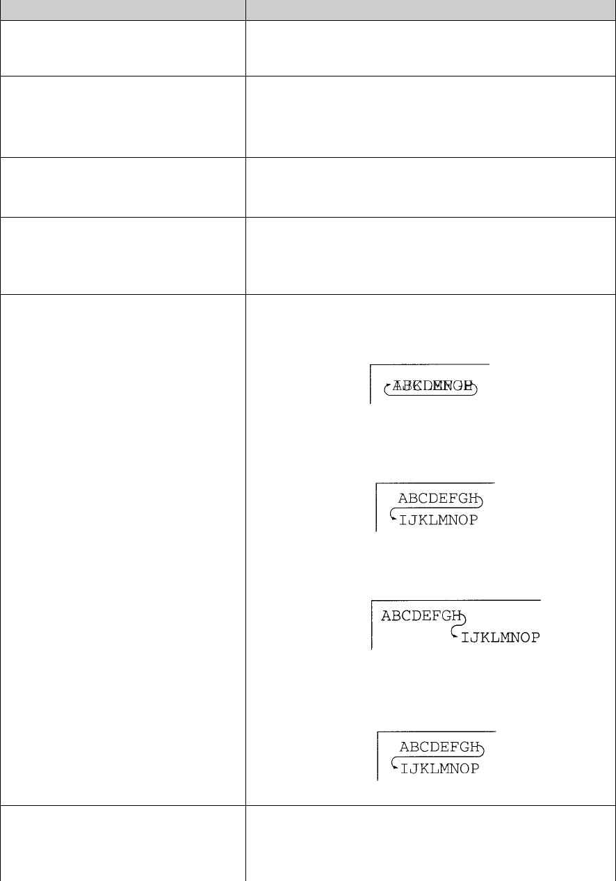
The initial printout contains a header, help menu 1, and <Function> menu 2. The header
tells you that the printer is in the Set-Up mode. The help menu provides a quick summary of
how to use buttons in the Set-Up mode.
The <FUNCTIONS> menu 2 is started from MACRO.
Buttons Set-Up Action
NEXT Move cursor Down to the next Function or Value
PREVIOUS Move cursor Up to the next Function or Value
ALT
-NEXT Select the Option or Value and Move cursor Right
ALT
-PREVIOUS Select the Option or Value and Move cursor Left
SETUP/EXIT Select the Option or value and Move to SAVE&EXIT
2
1
Using Set-Up Mode
4-5
Overview of the Set-Up Mode
Your Mobile Printer has five functions menu in setup mode.
When you press the NEXT KEY or PREVIOUS KEY, the following next or previous
<FUNCTIONS> menu is printed:
<FUNCTIONS>
MACRO
INSTALL
SAFE PANEL
RCALL-FACT
SAVE&EXIT
The following table summarizes the purpose of each function.
MACRO
Assigns print features to MACRO
INSTALL
Changes the Set-Up menu language, computer interface,
and paper feed control options
SAFE PANEL
REDY, PARK and LOAD require the ALT key to be used
as a two key operation for these functions
RCALL-FACT
Resets factory settings in MACRO and INSTALL
SAVE&EXIT
Exits the Set-Up mode and saves any changes made in
the Set-Up mode
Using Set-Up Mode
4-6
To select a function from the <FUNCTIONS> menu:
1. Repeatedly press the NEXT button or the PREVIOUS button to position the function
you require.
2. Press the ALT-NEXT button or the ALT-PREVIOUS button to select the function.
The printer prints the first option. The MACRO INSTALL and SAFE PANEL
functions contain options that have selectable values. The other functions have
neither options nor values. Repeatedly press the NEXT button or the PREVIOUS
button to position the option you require.
The first four Macro options are shown below.
<FUNCTIONS>
MACRO
<EMULATION>
<EMUL SERIAL>
<EMUL USB>
<EMUL WIRELESS>
3. Press the ALT-NEXT button or the ALT-PREVIOUS button to select the option.
The printer prints the first value. Repeatedly press the NEXT button or the
PREVIOUS button to position the value you require.
The EMUL WIRELESS values are shown below.
<FUNCTIONS>
MACRO
<EMULATION>
<EMUL SERIAL>
<EMUL USB>
<EMUL WIRELESS>
EPSON-EP2
IBM2390+
The current option and its values are reprinted when the ALT-PREVIOUS button is
released.
Using Set-Up Mode
4-7
Options with Pre-determined Values
For some options, you can choose among a limited set of pre-determined values. To select
such a value:
1. Repeatedly press the NEXT button or the PREVIOUS button to position the value
you require.
2. Press the ALT-PREVIOUS button to select the value. The printer prints the current
option.
3. After selecting the desired values, press the SETUP/EXIT button to reprint the
<FUNCTIONS> SAVE&EXIT.
Example: Changing the Vertical Pitch
To become familiar with the Set-Up mode, try the following example. This example
shows how to change the vertical pitch in Macro from 6 lines per inch to 8 lines per
inch.
1. Enter the Set-Up mode.
Turn the printer off and back on while pressing the READY button.
2. Select the Macro function.
Wait for the printer to stop printing and press the ALT-NEXT button to select the
Macro function and print the <EMULATION> option.
3. Print the menu of the vertical pitch option.
Since you only want to change the vertical pitch, press the NEXT button repeatedly
until the <VERT PITCH> option is printed. Press the ALT-NEXT button to select the
<VERT PITCH> option and print its values.
4. Change the vertical pitch from 6 to 8 lines per inch.
Press the NEXT button once to position the 8 LPI. Press the ALT-PREVIOUS
button to select 8 LPI. The option < VERT PITCH > is printed.
5. Exit the Macro function.
Since you do not want to make any other changes in MACRO, press the
SETUP/EXIT button. The <FUNCTIONS> SAVE&EXIT is reprinted.
6. Exit the Set-Up mode, saving the new vertical pitch.
Press the SETUP/EXIT button or the ALT-NEXT button or the ALT-PREVIOUS
button to save 8 lines per inch as the new power-on default in Macro , and then exit
Macro.
Press the SETUP/EXIT button again then the printer exits the Set-Up mode and
returns to the Ready state. These settings remain in effect until the next time they
are changed.
Using Set-Up Mode
4-8
Options with Undetermined Values
For some options, you can choose among a continuous range of many values. These
options are identified as follows
– <XXX-No of INCH>, which means the unit of the range is the Inch.
– <XXX-No of COLM>, which means the unit of the range is the Column.
– <XXX-No of LINE>, which means the unit of the range is the Line.
Example: Changing the Left Margin
This example shows how to change the left margin in Macro from column 1 to column 20.
1. Enter the Set-Up mode.
Turn the printer off and back on while pressing the READY button.
2. Select the Macro function.
Wait for the printer to stop printing. Then press the ALT-NEXT button to select the
Macro function options.
3. Print the menu of the left margin option.
Since you only want to change the left margin, press the NEXT button or the
PREVIOUS button until the <LEFT MARGN> option is printed. Press the ALT-
NEXT button to select the < LEFT MARGN > option and print its values.
4. Change the left margin from column 1 to column 20.
Press and hold the NEXT button nineteen times. When the button is released, the
new value is printed next to the current value. If the new value is not 20 COL,
repeat this operation. If it is 20 COL, press the ALT-NEXT button to select 20 COL.
20 COL is underlined, and the next option value is printed.
5. Exit the Macro function.
Since you do not want to make any other changes in MACRO, press the
SETUP/EXIT button. The <FUNCTIONS> SAVE&EXIT menu is then reprinted.
6. Exit the Set-Up mode, saving the new left margin.
Press the SETUP/EXIT button or the ALT-NEXT button or the ALT-PREVIOUS
button to save 20 columns as the new power-on default in Macro and exit Macro.
Press the SETUP/EXIT button again then the printer exits the Set-Up mode and
returns to the Ready state. These settings remain in effect until the next time they
are changed.
The chart on the next page summarizes how to select options such as emulation and font
and how to use the functions that do not have options.
Using Set-Up Mode
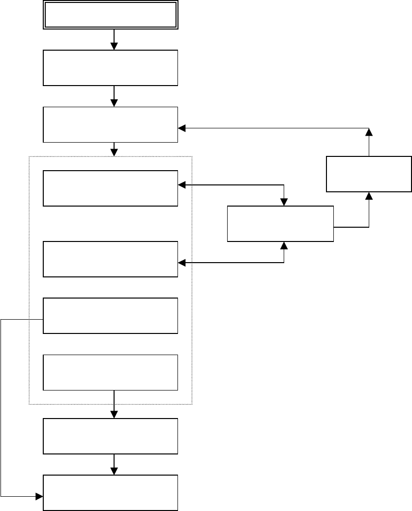
4-9
One of the following functions is selected
Enter Set-Up mode:
Turn power on with READY pressed
Printer prints help menu and
<FUNCTIONS> menu
Select values
RECALL FACTORY DEFAULTS
MACRO and INSTALL
SAFE PANEL
Press SAVE&EXIT, ALT-NEXT,
or
ALT-PREVIOUS
Printer saves changes and exits
Set-Up mode.
Press READY OR
ALT-PREVIOUS
Select functions
SAVE&EXIT
Using Set-Up Mode
4-10
Points to Remember
• We recommend that you use continuous forms paper for printing in the Set-Up
mode because the output will exceed a single page. To load paper, use the
FF/Load button.
• Whenever you enter the Set-Up mode, short help menus are printed at the top of
the page. Use the help menus for quick reference while in the Set-Up mode.
• When printing the option for each function, you can move either forward or
backward in the option list. To move forward (print the next option), press the NEXT
button. To move backward (print the previous option), press the PREVIOUS button.
• While in the <FUNCTIONS> menu or when selecting a function that contains
options and selectable values, press the SETUP/EXIT button to reprint the
<FUNCTIONS> menu SAVE&EXIT.
Macro Options and Values
•
Overprinted values are the factory settings.
• Some settings are overridden by commands from the computer.
• Options that differ by emulation are described at the end of the table.
MACRO Options Description
<EMULATION> Select the same emulation as that selected by your
software. See step 6, “Connecting the Printer to Your
Host System,” in the Installation Guide for information on
selecting an emulation.
EPSON-EP2 Epson printers using the EP2 emulation
IBM 2390+ IBM 2390+ printers
6820 6820 mode (Standard model doesn’t support this
functions)
PORT DEPEND The printer selects emulation according to the active
interface (such as serial, USB). See the next options.
<EMUL SERIAL> Select an emulation for the Serial interface. This is invalid
and skipped when PORT DEPEND is not selected for the
<EMULATION> option.
EPSON EP2 EP2 (factory setting)
IBM 2390+ IBM Proprinter 2390+ printers
6820 Not valid in Standard model
<EMUL USB> Select an emulation for USB interface. This is invalid and
skipped when PORT DEPEND is not selected for the
<EMULATION> option.
EPSON EP2 EP2 (factory setting)
IBM 2390+ IBM Proprinter 2390+ printers
6820 Not valid in Standard model
Using Set-Up Mode
4-11
MACRO Options Description
<EMUL WIRELESS> Select an emulation for the Wireless interface. This is
invalid and skipped when PORT DEPEND is not selected
for the <EMULATION> option.
EPSON EP2 EP2 (factory setting)
IBM 2390+ IBM Proprinter 2390+ printers
6820 Not valid in Standard model
<EMUL BLUETOOTH> Select an emulation for the Bluetooth interface. This is
invalid and skipped when PORT DEPEND is not selected
for the <EMULATION> option.
EPSON EP2 EP2 (factory setting)
IBM 2390+ IBM Proprinter 2390+ printers
6820 Not valid in Standard model
<FONT> Select a font to be active when the power is turned on.
For fixed-spaced fonts, be sure to change the horizontal
pitch as well.
DRAFT Draft font (lower resolution than letter quality, 3 times the
speed of letter quality)
COURIER
Courier font
ROMAN
ROMAN font
SANS SERIF
Sans Serif font
SCRIPT
Script font
BOLD
Bold font
GOTHIC
Gothic font
PRESTIGE
Prestige font
ORATOR
ORATOR font
OCR-A
OCR A font
OCR-B
OCR B font
<HORIZONTAL PITCH> ## CPI
10,12, 15, 17, 20 or 24
(characters per horizontal inch)
<VERTICAL PITCH> ## LPI
1,2, 3, 4, 5, 6, 7, 8, or 12
(lines per vertical inch)
## LPCM
1, 2, or 4
(lines per centimeter
)
<FORM LENGH> Specify the length of the page in inches or by the number
of lines per page.
## INCHES 3, 3.5, 4, 5.5, 6, 7, 8, 8.5, 11 (Letter size), 11 2/3 (A4
size), 12, 14, or 15
No of LINE 1 to 126 (66)
Number of lines per page
<LEFT MARGN> Specify the left margin by the number of the left column
(see “Print Area Definition” in Chapter 2, “Paper
Handling.”)
No of COLM 1 to 256
Number of the left column
<TOP OF FORM>
Specify the top of form in 1/60 inches. See “Print Area
Using Set-Up Mode
4-12
MACRO Options Description
Definition” in Chapter 2, “Paper Handling.”
## /60 IN
0 to 99
Number of 1/60 inches
<IGNORE FF>
Specify whether to ignore a form feed when the
current position is at the top of a form.
NO
YES
Always perform a commanded form feed.
Ignore the form feed when at the top of a form.
<TOP MRGIN>
Specify the number of the top line. See “Print Area
Definition” in Chapter 2, “Paper Handling.”
## LINES
1 to 126 (66)
<BOTTOM MRG>
Specify the number of the bottom line. See “Print Area
Definition” in Chapter 2, “Paper Handling.”
## LINES
1 to 256 (66)
Number of the bottom line
<LINE MODE>
Specify the effect of CR (Carriage Return) and LF
(Line Feed) codes.
CR=CR
CR=LF+CR
LF=LF
LF=LF+CR
CR=CR:
No line feed is added to a carriage return
CR=LF+CR
: A line feed is added to each carriage
return.
LF=LF:
No carriage return is added to a line feed.
LF=LF+CR:
A carriage return is added to each line
feed.
<PRINT DIR>
UNIDIR
Unidirectional printing. Unidirectional printing is used
for printing that needs precise vertical alignment.
Unidirectional printing is slower than bi-directional
Using Set-Up Mode
4-13
MACRO Options Description
printing.
BIDIR
Bi-directional printing. The printer prints in either
direction while seeking the next print direction for a
shorter print time. The unidirectional command is
ignored.
SOFT CONTROL
(Software Control)
The print direction follows a command from the
computer. If no command is sent, print direction is bi-
directional.
=IBM&EPSON=========
The following are the Set-Up options for the IBM and
EPSON emulation only.
<CODE PAGE>
Selects the character set. Character sets can be used
according to the selected emulation.
Code Page
437, 850, 860, 863, 865, 851, 852, 853, 855, 857, 866,
869, USSR GOST, 864, 437G, 920, 858, 923
=IBM DEFLTS=========
The following are the Set-Up options for the IBM
Proprinter 2390+ emulation only.
<IBM SET 1/2>
Specify a character set of the IBM Proprinter 2390+.
IBM SET 1
IBM character set 1
IBM SET 2
IBM character set 2
<IBM DBL HIGH>
Specify whether the character height is doubled. If
specified, change the vertical pitch also.
NO
Standard character height
YES
Double character height
<IBM AGM>
Specify whether the Alternate Graphics Mode (AGM)
is used; in other words, is the printer compatible with
the IBM Graphics printers?
NO
The base of line spacing is 1/72 inch or 1/216 inch.
YES
The base of line spacing is 1/60 inch or 1/180 inch.
=EPSON DFLTS=========
The following are the Set-Up options for the Epson
EP2 emulation only.
<E-CHR SET>
Select a national character set.
USA
American English
FRANCE
French
GERMANY
German
UK
British English
DENMARK1
Danish 1
SWEDEN
Swedish
ITALY
Italian
SPAIN1
Spanish 1
JAPAN
Japanese
NORWAY
Norwegian
DENMARK2
Danish 2
SPAIN2
Spanish 2

Using Set-Up Mode
4-14
MACRO Options Description
LATIN AM
Latin American
< 6820 SEQ >
Select Parser control
NO
Disable 6820 control sequences
YES
Enable 6820 control sequences
< 6820 PROT >
Select Protocol mode
NO
Disable the 6820 protocol
YES
Enable the 6820 protocol

Using Set-Up Mode
4-15
INSTALL Options and Values
• Overprinted values are the factory settings.
INSTALL Options Values Description
<LANGUAGE>
Specify a language to be used to print the Set-
Up menu functions and options.
ENGLISH English
DEUTSCH German
ESPANOL Spanish
FRANCAIS French
ITALIANO Italian
<TEAR>
Specify the (auto) start timing of tear off
feeding.
AUTO 1 SEC 1 second after data stops from the computer
AUTO 2 SEC 2 seconds after data stops from the computer
AUTO 3 SEC 3 seconds after data stops from the computer
AUTO 4 SEC 4 seconds after data stops from the computer
AUTO 5 SEC 5 seconds after data stops from the computer
MANUAL Feed the paper for tear-off when the READY
button is pressed changing to pause mode.
NO TEAR Tear off feeding is inhibited under any
conditions.
<S-SHEET LD>
Specify the (auto) start timing of single sheet
loading.
AUTO 1 SEC 1 second after a single sheet is set on the
platen
AUTO 2 SEC 2 seconds after a single sheet is set on the
platen
AUTO 3 SEC 3 seconds after a single sheet is set on the
platen
AUTO 4 SEC 4 seconds after a single sheet is set on the
platen
AUTO 5 SEC 5 seconds after a single sheet is set on the
platen
MANUAL Load a single sheet when the FF/Load button
is pressed.
<BUFFER>
Assign buffer memory as the input buffer.
2 KBYTE 2K bytes
8 KBYTE 8K bytes
16 KBYTE 16K bytes
32 KBYTE 32K bytes
64 KBYTE 64K bytes

Using Set-Up Mode
4-16
INSTALL Options Values Description
Note:
The larger the input buffer selected, the
smaller the download buffer becomes. Even
with 64K bytes of input buffer, a minimal
download buffer is provided. If you need a
larger capacity for downloading fonts,
reduce the input buffer.
<I/F TYPE>
Select the type of interface to the computer.
AUTO Both interfaces are ready for communication.
The printer communicates with the interface
from which it first receives data. The interface
is active until the input buffer becomes empty.
SERIAL RS-232 Serial interface
USB USB interface
WIRELESS Wireless interface
BLUETOOTH Bluetooth interface
<BAUD RATE>
The baud rate is in bps (bits per second).
Select the same baud rate as that used by your
computer or modem.
4800 BPS 4800 Bits Per Second
9600 BPS 9600 Bits Per Second
19200 BPS 19200 Bits Per Second
38400 BPS 38400 Bits Per Second
<PARITY>
Parity setting
Select the same word parity setting that is used
by your computer or modem.
NONE None causes transmission in both directions
without parity bit
ODD The bytes are checked to ensure they have
odd parity.
EVEN The bytes are checked to ensure they have
even parity.
<DATA BIT>
Word Length setting
Select the same word length setting that is
used by your computer or modem.
8 BIT 8 Data bits per data byte
7 BIT 7 Data bits per data byte
<STOP BIT>
Word Length setting
Select the same word length setting that is
used by your computer or modem.
1 BIT 1 Stop bit per data byte
2 BIT 2 Stop bits per data byte
<BUFFER CTL> The ready/busy control method.
DTR Hardware control via the DTR lead.
XON/XOFF Data control using DC1 and DC3 control
Using Set-Up Mode
4-17
INSTALL Options Values Description
characters.
6820 PROT For 6820 emulation
<DISC FAULT> Disconnect on a fault condition
NO Do not disconnect.
DROP DTR DTR will change to inactive state.
PULSE DTR DTR will pulse to inactive and then back to the
normal active state.
<PWRDNTIME> Sets time for idle power down action
0 Disables idle power down timeout
1-96 Hours to turn off power
Safe Panel
• If the value of safe panel is “YES”, READY, PARK and LOAD require the ALT key
to be used as a two key operation for these functions in Normal Operation Mode of
printer.
• If the value of safe panel is “NO”, READY, PARK and LOAD key are operated as
Normal Operation Mode, ALT key is not required.
Recalling Factory Settings
Factory settings are those settings pre-selected at the factory. To recall (reset) the
factory settings, select the RCALL-FACT function and press the ALT-NEXT button
or the ALT-PREVIOUS button.
Options under the MACRO, INSTALL, and ADJUST functions are all initialized to the
factory settings.
Exiting and Saving
This section describes how to exit the Set-Up mode while saving any changes you
have made.
To exit the Set-Up mode with the settings saved, first select the SAVE&EXIT function
and then press the ALT-NEXT button or the ALT-PREVIOUS button.
Any settings changed while in the Set-Up mode are saved as the new power-on
defaults for the printer. The new defaults remain active until you change them
again.
Using Set-Up Mode
4-18
Using the Diagnostic Functions
Print Configuration Function
This function prints a list of all the printer’s currently selected values. This function is useful
for checking the printer settings when you first enter the Set-Up mode or just before you exit.
1. To enter the Printer Configuration mode:
1) Make sure that the tractors are loaded with continuous feedpaper and that the
paper select lever is set forward.
2) Turn the printer off.
3) Turn the printer back on while pressing the ALT button.
2. The printer starts to print a list of the currently selected values. The pre-selected
factory settings are shown on the opposite page.
3. To exit the Printer Configuration mode:
After the printer finishes printing the list of values, press the SETUP/EXIT button
Using Set-Up Mode
4-19
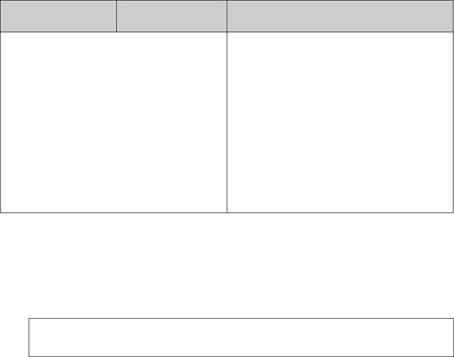
Printout of Factory Settings Using the PRINT Function
3ULQWHU&RQILJXUDWLRQ
xxxxxxxxx
F/W Version V1.00
IPL Version V1.03
CG Version V1.01
INSTALL
Options Value
----------------------------
LANGUAGE ENGLISH
TEAR AUTO 1
SEC
S-SHEET LD AUTO 1
SEC
BUFFER 64
KBYTE
I/F TYPE AUTO
BAUD RATE 9600 BPS
PARITY
NONE
DATA BIT 8 BIT
STOP BIT 1
BUFFER CTL DTR
DISC FAULT NO
PWRDWNHRS 16
HOUR(S)
SAFE PANEL
Options Value
----------------------------
SAFE PANEL NO
MENU-ACCES
Options Value
----------------------------
MENU
-
ACCES
ALL FUNC
MACRO
Options Value
----------------------------
EMULATION EPSON-EP2
EMUL SERIAL EPSON-EP2
EMUL USB EPSON-EP2
EMUL WIRELESS EPSON-EP2
EMUL BLUETOOTH EPSON-EP2
FONT DRAFT
HORZ PITCH 10 CPI
VERT PITCH 6 LPI
FORM LENGTH 11
INCHES
LEFT MARGN 1 COL
TOP OF FORM 0 /60 IN
IGNORE FF YES
TOP MARGIN 1 LINES
BOTTOM MARGIN 66 LINES
CR CODE CR=CR
LF CODE LF=LF+CR
PRINT DIR SOFT CONTRL
<IBM&EPSON>
CODE PAGE CP 437
<IBM DEFLTS>
I-SET 1/2 IBM SET 1
I-DBL HIGH NO
IBM AGM NO
<EPSON DEFLTS>
E-CHR SET USA
1 2 3 4 5 6 7 8 9 0 1 2 3 4 5 6 7 8 9 0 1 2 3 4
Using Set-Up Mode
4-20
Printing Test Function
The printing test function prints test pages independently of your computer to check printing
operations and quality. It does not check the interface between the computer and the printer.
The printing test prints all of the characters available in the ASCII character set.
1. To enter the Printing Test mode:
1) Make sure that the tractors are loaded with continuous feedpaper and that the
paper select lever is set forward.
2) Turn the printer off.
3) Turn the printer back on while pressing the “LOAD/FF” button.
Note: Do not press any buttons alone or in combination except for pressing the
LOAD button alone when turning the printer on, to avoid initiating
unexpected tests not permitted for the user.
2. The printer starts to print rolling ASCII data as shown below.
3. To exit the Printer Configuration mode:
Printing Test mode is continues until power OFF.
_!"#$%&'()*+,-./0123456789:;<=>?@ABCDEFGHIJKLMNOPQRSTUVWXYZ[
!"#$%&'()*+,-./0123456789:;<=>?@ABCDEFGHIJKLMNOPQRSTUVWXYZ[\
"#$%&'()*+,-./0123456789:;<=>?@ABCDEFGHIJKLMNOPQRSTUVWXYZ[\]
#$%&'()*+,-./0123456789:;<=>?@ABCDEFGHIJKLMNOPQRSTUVWXYZ[\]^
$%&'()*+,-./0123456789:;<=>?@ABCDEFGHIJKLMNOPQRSTUVWXYZ[\]^_
%&'()*+,-./0123456789:;<=>?@ABCDEFGHIJKLMNOPQRSTUVWXYZ[\]^_`
&'()*+,-./0123456789:;<=>?@ABCDEFGHIJKLMNOPQRSTUVWXYZ[\]^_`a
'()*+,-./0123456789:;<=>?@ABCDEFGHIJKLMNOPQRSTUVWXYZ[\]^_`ab
()*+,-./0123456789:;<=>?@ABCDEFGHIJKLMNOPQRSTUVWXYZ[\]^_`abc
)*+,-./0123456789:;<=>?@ABCDEFGHIJKLMNOPQRSTUVWXYZ[\]^_`abcd
.
.
.
.
.
.
.
.
.
_!"#$%&'()*+,-./0123456789:;<=>?@ABCDEFGHIJKLMNOPQRSTUVWXYZ[
!"#$%&'()*+,-./0123456789:;<=>?@ABCDEFGHIJKLMNOPQRSTUVWXYZ[\
"#$%&'()*+,-./0123456789:;<=>?@ABCDEFGHIJKLMNOPQRSTUVWXYZ[\]
#$%&'()*+,-./0123456789:;<=>?@ABCDEFGHIJKLMNOPQRSTUVWXYZ[\]^
$%&'()*+,-./0123456789:;<=>?@ABCDEFGHIJKLMNOPQRSTUVWXYZ[\]^_
%&'()*+,-./0123456789:;<=>?@ABCDEFGHIJKLMNOPQRSTUVWXYZ[\]^_`
&'()*+,-./0123456789:;<=>?@ABCDEFGHIJKLMNOPQRSTUVWXYZ[\]^_`a
'()*+,
-
./0123456789:;<=>?@ABCDEFGHIJKLMNOPQRSTUVWXYZ[
\
]^_`ab
Using Set-Up Mode
4-21
Hex Dump Mode
The Hex Dump mode prints data and commands in hexadecimal characters and
abbreviated control codes. The ASCII characters are used for printing. No characters are
printed for hexadecimal codes 80 to FF. The Hex Dump mode is useful for checking whether
your computer is sending the correct commands to the printer and whether the printer is
executing the commands correctly. It is also useful for debugging software programs.
1. To enter the Printing Test mode:
1) Make sure that the tractors are loaded with continuous feedpaper and that the
paper select lever is set forward.
2) Turn the printer off.
3) Turn the printer back on while pressing the “READY/CLEAR” + “ALT” buttons.
Note: Do not press any buttons alone or in combination except for pressing the
READY and ALT buttons alone when turning the printer on, to avoid
initiating unexpected tests not permitted for the user.
2. Print the Hex Dump.
1) To start Hex Dump printing, send your file or program to the printer. The printer
goes online and prints the Hex Dump.
2) Press the READY button to pause and resume printing in Hex Dump mode. To
resume Hex Dump printing, press the READY button again.
3) To print another Hex Dump, send another file to the printer.
3. Exit the Hex Dump mode
Turn the printer off to exit the Hex Dump mode.
4. Sample of Hex Dump printing format
0000 00 01 02 03 04 05 . . . . 0C 0D 0E 0F
................
0010 10 11 12 13 14 15 . . . . 1C 1D 1E 1F
................
0020 20 21 22 23 24 25 . . . . 2C 2D 2E 2F
!"#$%&'()*+,-./
0030 30 31 32 33 34 35 . . . . 3C 3D 3E 3F
0123456789:;<=>?
0040 40 41 42 43 44 45 . . . . 4C 4D 4E 4F
@ABCDEFGHIJKLMNO
0050 50 51 52 53 54 55 . . . . 5C 5D 5E 5F
PQRSTUVWXYZ[\]^_
Address Hex data ASCII
Using Set-Up Mode
4-22
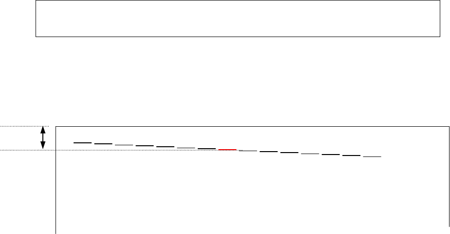
Printing Alignment Adjustment
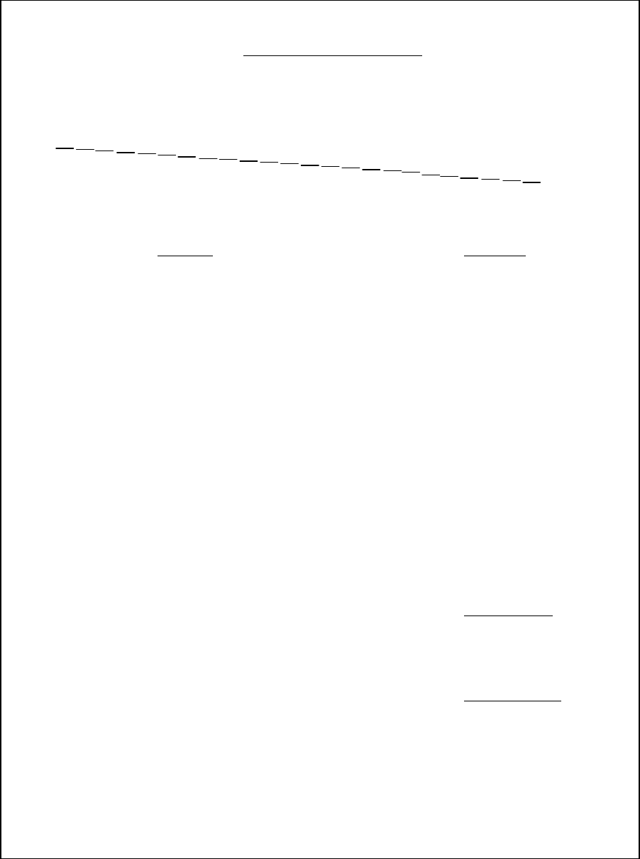
This function performs adjustment Bi-directional alignment.
In bidirectional printing, characters are printed from left to right tend to misalign with
characters printed from right to left as shown below:
The vertical alignment function corrects the vertical character displacement that
sometimes occurs with bidirectional printing and results in a poor appearance especially in
printing tables. This function is defined as one of the power-on initiated test functions. If you
notice misaligned printing, start this function to check and correct the vertical print alignment.
1. To enter the Printing Alignment Adjustment Function:
1) Make sure that the tractors are loaded with continuous feedpaper and that the
paper select lever is set forward.
2) Turn the printer off.
3) Turn the printer back on while pressing the “READY/CLEAR” + “LOAD/FF” buttons.
Note: Do not press any buttons alone or in combination except for pressing the
READY and LOAD buttons alone when turning the printer on, to avoid
initiating unexpected tests not permitted for the user.
2. Adjust the vertical print alignment at High Speed.
After Paper is loaded, the format of adjustment for Bi-directional Alignment of High
Speed is printed and the paper will automatically advance for viewing after the printing
is complete. The message of ”Bi-Dir Align Adjust1 = xx” is printed.
Align Adjust 1 = 08
Using Set-Up Mode
4-23
An adjustment value is chosen by NEXT and PREVIOUS Key. The adjustment
range is "01-15", and the center value is "08". By pressing SETUP/EXIT Key, the
adjustment value for High Speed is determined and the adjustment value for High
Speed is saved.
3. Adjust the vertical print alignment at Low Speed.
Adjustment Bi-directional Alignment for Low Speed is performed immediately, after
the adjustment value for High Speed is saved.
After Paper is loaded, the format of adjustment for Bi-directional Alignment of Low
Speed is printed and the paper will automatically advance for viewing after the printing
is complete. The message of ”Bi-Dir Align Adjust 2 = xx” is printed.
An adjustment value is chosen by NEXT and PREVIOUS Keys. The adjustment
range is "01-15", and the center value is "08". By pressing SETUP/EXIT Key, the
adjustment value for High Speed is determined and the adjustment value for Low
Speed is saved.
4. Printing new settings of alignment and Exit the vertical alignment function.
Press the SETUP/EXIT button to save the new vertical alignment settings. The new
adjustment values of Bi-directional Alignment are printed after both High Speed and
Low Speed are saved; the paper is automatically advanced for viewing after the
printing is completed, then exit the vertical alignment function.
Align Adjust 2 = 08
Align Adjust 1 = xx
Align Adjust 2 = xx

Using Set-Up Mode
4-24
Note: To exit the vertical alignment function without saving changes, turn the printer
off.
Using Set-Up Mode
4-25
Top Adjustment Function
Print positions often change gradually when you use the printer over long periods
of time. The ADJUST function allows you to adjust these positions by fine-tuning the
Top-of-Form origin.
1. To enter Top Adjustment Function:
1) Make sure that the tractors are loaded with continuous feedpaper and that the
paper select lever is set forward.
2) Turn the printer off.
3) Turn the printer back on while pressing the “PARK” buttons.
Note: Do not press any buttons alone or in combination except for pressing the
PARK button alone when turning the printer on, to avoid initiating
unexpected tests not permitted for the user.
2. To set Top Adjustment value:
1) The format of adjustment Loading Position is printed as below, 15 patterns of
adjustment Loading Position are printed.
2) The format of Loading Position is printed and the paper is automatically advanced
for viewing after the printing is complete. The message of ”Loading Position Pos =
xx” is printed.
3) Press NEXT and PREVIOUS Key to choose the new top position. The adjustment
range is "01-15", and the center value is "08".
It is possible to adjust different values for Tractor and Manual
3. Printing new value
By pressing SETUP/EXIT Key, the adjustment value for Loading Position is
determined and the adjustment value for Loading Position is saved.
10/60inch
01 02 03 04 05 06 07 08 09 10 11 12 13
14 15
Loading Position ዙ xx

Using Set-Up Mode
4-26
The new adjustment values of Loading Position is printed. The paper is
automatically advanced for viewing after the printing is complete. After ejecting a
paper, the message” Loading Position = xx” is printed.
4. Exit the Top Adjustment mode
Turn the printer off to exit the Top Adjustment mode.
Loading Position ዙ xx
…
…
Loading Position
ዙ
yy
Note) ”yy” is New adjustment value
Using Set-Up Mode
4-27
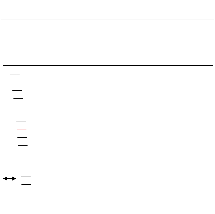
Setting of The First Dot Position on The Left Side Function
Print positions often change gradually when you use the printer over long periods
of time. This ADJUST function allows you to adjust these positions by fine-tuning the
Left Margin origin.
1. To enter Adjustment Function:
1) Make sure that the tractors are loaded with continuous feedpaper and that the
paper select lever is set forward.
2) Turn the printer off.
3) Turn the printer back on while pressing the “READY/CLEAR” + “ALT” +
“LOAD/FF ” buttons.
Note: Do not press any buttons alone or in combination except for pressing the
“READY/CLEAR” + “ALT” + “LOAD/FF” buttons alone when turning the
printer on, to avoid initiating unexpected tests not permitted for the user.
2. To set Adjustment value:
1) The format of adjustment of setting of the first dot Position on the left side is printed
as below, 15 patterns of adjustment Position are printed.
1st Print Position ዙ xx
+
++
+
+
+ +
+
+
+ +
+
+
+ +
+
+
+ +
+
+
+ +
+
+
+ +
+
+
+ +
+
+
++
+
+
++
+
+
+ +
+
+
+ +
+
+
+ +
+
+
+ +
+
, Q F K
, Q F K, Q F K
, Q F K
+
+ +
+

Using Set-Up Mode
4-28
2) After the format of setting of the first dot Position on the left side is printed, the
paper is automatically advanced for viewing after the printing is complete. The
message of ”1
st
Print Position Pos = xx” is printed.
3) Press NEXT and PREVIOUS Key to choose the new first dot position on the left
side. The adjustment range is "01-15", and the center value is "08".
It is possible to adjust different values for Tractor and Manual
3. Printing new value
By pressing SETUP/EXIT Key, the adjustment value for the first dot position on the
left side is determined and the adjustment value is saved.
The new adjustment value of the first dot position on the left side is printed. The
paper is automatically advanced for viewing after the printing is complete. After
ejecting a paper, the message” 1
st
Print Position = xx” is printed.
4. Exit the setting of the first dot position on the left side mode
Turn the printer off to exit this mode.
1
st
Print Position ዙ xx
…
…
1
st
Print Position ዙ yy
Note) ”yy” is New adjustment value
Using Set-Up Mode
4-29
Changing Menu Access Options
You can restrict the access to the Set-Up functions to avoid accidentally changing the Set-Up
options.
MENU ACCESS Option and Values
•
Overprinted values are the factory settings.
MENU ACCESS
Options
Values Description
<MENU-ACCES>
Specify the type of access to the Set-Up functions
from the control panel or from the <FUNCTIONS>
menu.
ALL FUNC
All functions are accessible.
MACRO ONLY
Only MACRO functions are accessible from the
<FUNCTIONS> menu.
NO ACCESS
Set-Up mode is inaccessible.
SAFE PANEL
READY, PARK and LOAD require the ALT key to
be used as a two key operation for these
functions.
Note:
You can return to the All Functions
Accessible mode by turning the printer on
while pressing the ALT, PARK and LOAD
buttons at the same time. The printer enters
the Set-Up mode with this operation.
1. To enter Menu Access mode:
1) Make sure that the tractors are loaded with continuous feedpaper and that the
paper select lever is set forward.
2) Turn the printer off.
3) Turn the printer back on while pressing the “LOAD/FF” + “PARK” + “ALT” buttons.
Note: Do not press any buttons alone or in combination except for pressing the
LOAD, PARK and ALT buttons alone when turning the printer on, to avoid
initiating unexpected tests not permitted for the user.
2. To change Menu Access Option and values
1)
Press the NEXT( LOAD/FF) button to move to next option;
2)
Press the PREVIOUS( PARK) button to move to previous option;
3)
Press the ALT-NEXT buttons to select the Option or value and move down;
4)
Press the ALT-PREVIOUS buttons to select the Option or value and move up;
5)
Press SETUP/EXIT key to save the value and move to SAVE&EXIT menu;
Using Set-Up Mode
4-30
3. Exit the Menu Access mode
Turn the printer off to exit the Menu Access mode.

Using Set-Up Mode
4-31
Setting Setup Mode to Default Value (Standard)
This function can initialize the printer to Standard default.
1. To enter setting setup mode to default value(standard):
1) Turn the printer off.
2) Turn the printer back on while pressing the “PARK” + “READY/CLEAR” buttons.
Note: Do not press any buttons alone or in combination except for pressing the
PARK and READY/CLEAR buttons alone when turning the printer on, to
avoid initiating unexpected tests not permitted for the user.
2. Exit the setting setup mode to default value(standard):
After the setting completes, the printer will automatically restart in the power-up state.
Setting Setup Mode to Default Value (6820 Mode)
This function can initialize the printer to 6820 mode default.
1. To enter setting setup mode to default value(6820 mode):
1) Turn the printer off.
2) Turn the printer back on while pressing the “PARK” + “ALT” buttons.
Note: Do not press any buttons alone or in combination except for pressing the
PARK and ALT buttons alone when turning the printer on, to avoid initiating
unexpected tests not permitted for the user.
2. Exit the setting setup mode to default value(6820 mode):
After the setting completes, the printer will automatically restart in the power-up state.

Using Set-Up Mode
4-32
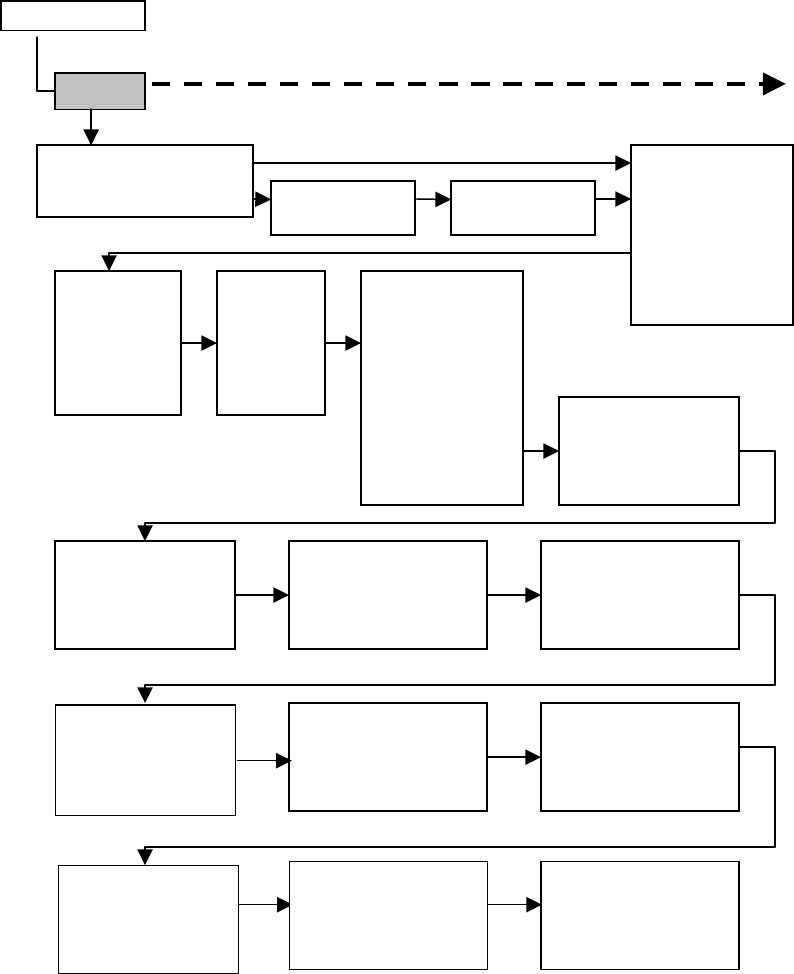
Set-Up Mode Quick Reference
The following flowchart shows how the Set-Up mode is organized.
Note: Asterisks (*) indicate factory settings.
Using Set-Up Mode
4-33
SET-UP MODE
MACRO
EMULATION EPSON EP2 *
IBM PPX24
RESERVED
PORT DEPEND EMUL SERL
EPSON EP2 *
IBM PPX24
EMUL PARL
EPSON EP2 *
IBM PPX24
FONT
DRAFT *
HSDRAFT
HI-IMPACT
PICA
COURIER
PRESTIGE
COMPRESSED
BOLDFACE
TIMELESS
NINBUS-SAN
OCR A
HORIZ PITCH
10 CPI *
12 CPI
13.2 CPI
15 CPI
16.5 CPI
17 CPI
18 CPI
20 CPI
VERT PITCH
2 LPI
3 LPI
4 LPI
6 LPI *
8 LPI
1 LPCM
2 LPCM
4 LPCM
FORM LENGTH
3 INCHES
3.5 INCHES
4 INCHES
5.5 INCHES
6 INCHES
7 INCHES
8 INCHES
8.5 INCHES
11 INCHES *
11 2/3 INCH
12 INCHES
14 INCHES
15 INCHES
No of LINE
LEFT MARGN-No of COLM
1 COL *
2 COL
.
.
255 COL
256 COL
TOP OF FRM-No of INCH
0 /60 IN *
1 /60 IN
.
.
99/60 IN
TOP MRGN -No of LINE
1 LINES *
.
.
256 LINES
LINE MODE
LF=LFCR=CR *
LF=LF+CR
CR=LF+CR
LFCR=LF+CR
PAPER SRC
TRACTOR *
MANUAL
RESVD 1
RESVD 2
RESVD 1/2
IGNORE FF
NO
YES
EPSON DFLT==========
<E-CHR SET>
<6820 SEQ>
<6820 PROT>
BOTTOM MRG-No of LINE
1 LINES
.
66 LINES
*
.
256 LINE
S
PRINT DIR
UNIDIR
BIDIR
SOFT CNTRL *
IBM DEFLTS===========
<I-SET ½>
<I-DBL HIGT>
<IBMAGM>
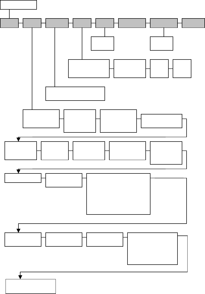
Using Set-Up Mode
4-34
SET-UP MODE
PRINT ADJUST TESTS RCALL-FACT MENU-ACCES SAVE&EXIT
PRINT-T
HEX-DUMP
SERIAL-T
PARALLEL-T
ALL FUNC *
MACRO ONLY
NO ACCESS
SAFE PANEL
S-SHEET LD: AUTO 1 SEC *
AUTO 2 SEC
AUTO 3 SEC
AUTO 4 SEC
AUTO 5 SEC
MANUAL
RSVD1 MNUAL ADJ: -10/60 IN
:
0 /60 IN *
:
10/60 IN
FANFOLD ADJ: -10/60 IN
:
0 /60 IN *
:
10/60 IN
INSTALL
RSVD2
ERROR BEEP: ONE *
CONTINUOUS
OFF
TEAR: AUTO 1 SEC *
AUTO 2 SEC
AUTO 3 SEC
AUTO 4 SEC
AUTO 5 SEC
MANUAL
NO TEAR
LANGUAGE: ENGLISH *
DEUTSCH
ESPANOL
FRANCAIS
ITALIANO
BUFFER: 2 KBYTE
8 KBYTE
16 KBYTE
32 KBYTE
64 KBYTE *
BIT&PARITY: 7 EVEN
7 ODD
7 SPACE
7 MARK
8 EVEN
8 ODD
8 NONE *
AUTO SW : 2 SEC *
4 SEC
:
18 SEC
20 SEC
BAUD RATE: 600 BPS
1200 BPS
2400 BPS
4800 BPS
9600 BPS *
19200 BPS
I/F TYPE: PARALLEL
SERIAL
AUTO *
I-SET 1 / 2: IBM SET 1 *
IBM SET 2
(IBM DEFLTS)
DEFLT SET: CP 210 CP DHN ELOT928
CP 220 TURKEY LTN POLISH
CP 437 * ECMA 94 LITHUANY 1
CP 850 ISO LATIN 1 LITHUANY 2
CP 851 ISO LATIN 2 MIK
CP 852 HUNGARY MACEDONIAN
CP 857 SLOVENY
CP 858 ISO LATIN9
CP 860 POLAND
CP 862 MAZOWIA
CP 863 KAMENIC
CP 865 CYRILLIC
CP 866 ELOT927
(IBM & EPSON)
DISC FAULT: NO *
DROP DTR
PULSE DTR
BUFFER CTL: DTR
XON/XOFF *
I-DBL HIGT: NO *
YES
(IBM DEFLTS)
IBM AGM: NO *
YES
(IBM DEFLTS)
E-CHR SET: USA * JAPAN
FRANCE NORWAY
GERMANY DENMARK
UK SPAIN 2
DENMARK 1 LATIN AM
SWEDEN KOREA
ITALY LEGAL
SPAIN 1
(EPSON DFLT)
NETWORK
NETW ORK: IP --- LSB to MSB
NETMASK --- LSB to MSB
GATEW AY --- LSB to MSB
PWRDNHRS: 0 Disable
1-96 Enable/Set