TOSHIBA TEC Singapore S-0601 Dot Printer User Manual Ch D Interface Rev 0 b
TOSHIBA TEC Singapore Pte Ltd Dot Printer Ch D Interface Rev 0 b
Contents
- 1. Users Manual 1
- 2. Users Manual 2
- 3. Users Manual 3
- 4. Users Manual 4
- 5. Users Manual 5
- 6. Users Manual 6
- 7. Users Manual 7
- 8. Users Manual 8
- 9. Users Manual 9
- 10. Users Manual 10
- 11. Users Manual 11
- 12. Users Manual 12
- 13. Users Manual 13
- 14. Users Manual 14
- 15. Users Manual 15
- 16. Users Manual 16
- 17. Users Manual 17
- 18. Users Manual 18
Users Manual 16
D
Interface Information
This printer can communicate with a computer through a serial interface,
a usb interface, a Blue Tooth wireless interface, an IEEE 802.11B wireless interface.
Interfaces may vary from unit to unit depending on which configuration is purchased.
.
This appendix provides information you may need for wiring your own interface cables or for
programming computer-to-printer communications. Most users do not need the information in
this appendix. This information is most useful to people who specify how to configure and
install these printers. To simply connect your printer to your computer, follow “Connecting the
Printer to Your Host System,” in the Installation Guide.
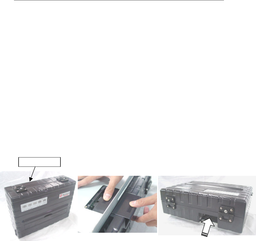
Removing the Connectivity Cover
To connect the printer through an IEEE 802.11B wireless interface , you must first remove
the connectivity cover on the bottom side of the printer.
1. Locate connectivity cover on the bottom side of the printer.
2. Push the top of the connectivity cover slightly inward.
3. Pull the connectivity cover slightly downward and out.
4. Connect the desired Wireless LAN module
Connectivity Cover
Connectivity Cover

Interface Information
D-2
Serial Interface
Use the cable that comes with the printer or equivalent. If you prepare a cable separately,
the cable connector at the printer side should be an equivalent that conforms to EIA
standards.
The following table shows the pin assignments that are used.
Pin No. Signal Name Description
2 TXD
(Transmit Data)
This line is for transmission of data from Printer to PC. The
characteristics of the data transmitted are specified by the
function menu. The only data that will be transmitted are
XON (x’11’) and XOFF (x’13’) signals. CTS must be high for
transmission to take place.
3 RXD
(Receive Data)
This line is for receiving data from PC. The serial
interface will not accept any data unless DSR is on.
4 RTS
(Request to Send)
This line will be set high and will remain high after the serial
interface finishes its Reset.
6
DTR
(Data Terminal
Ready)
This line will be set high after the serial interface finishes its
Reset sequence. However if Ready/busy handshake
protocol is selected, this line is used to indicate to PC
whether or not Printer is ready to receive any more data.
7
DSR
(Data Set Ready)
DSR is used as another method of providing data integrity.
Data will not be accepted unless DSR is high.
8 CTS
(Clear to Send)
This line will be monitored only if the XON/XOFF protocol is
selected because CTS must be high in order for the serial
interface to transmit data
Interface Information
D-3
Serial Options
The serial options for the computer and the printer must match. Use the printer control
panel, the computer operating system, or your software to change options specified as
“selectable.”
Transmission Asynchronous, full duplex
Mode:
Speed: 4800, 9600, 19200 or 38400 baud (selectable)
Data bits: 7 or 8 bits (selectable)
Parity bit: Even, odd, or none (selectable)
Start bit: 1 bit
Stop bit: 1 or 2 bits (selectable)
Buffer control: XON/XOFF (DC1/DC3) or DTR (Data Terminal Ready)
(selectable)
Buffer size: 2K, 8K, 16K, 32K, or 64K bytes (selectable)

Interface Information
D-4
Buffer Control
Buffer control is a communication emulation used by the computer terminal and the
printer to secure data transmission between the two devices. The buffer control
ensures that the computer does not send information to the printer faster than the
information can be processed in the printer. By telling the computer when the printer
can receive data, the buffer control prevents the printer’s buffer from overflowing.
This printer offers a choice of two different buffer controls for connection to a variety of
computers: XON/XOFF and DTR. If you computer documentation does not
recommend a particular buffer control, try DTR. The following table describes the
buffer control.
NOTE: XON/XOFF is the default setting from the factory.
Buffer Control Description
XON/XOFF (DC1/DC3) When the printer is ready to receive data, it sends the XON
(DC1) code (hex 11). When fewer than 255 bytes of space
remain in the buffer (or when the printer is taken offline), the
printer sends the XOFF (DC3) code (hex 13). (When the input
buffer is configured for 256 bytes, the buffer limit is reduced
from 255 bytes to 63 bytes.) The computer must stop
transmitting data within 255 (63) characters of receiving the
XOFF code, or information may be lost. If the paper runs out,
the printer sends an NAK code (hex 15).
DTR DTR is a hardware buffer control; that is, the Ready Out signal
on the interface cable. (DTR) is used to control the flow of
data rather than the transmission of a character code. When
the printer is ready to receive data, DTR is high. When fewer
than 255 (63) bytes of space remain in the buffer (or when the
printer is taken offline), DTR is low. The computer must stop
transmitting data within 255 (63) characters of DTR being low,
or information may be lost.

Interface Information
D-5
USB Interface (Universal Serial Bus)
Features
Full compliance with the Universal Serial Bus Specification Revision 2.0.
USB Function Controller with two FIFO-based Endpoints:
One bidirectional Control Endpoint 0 (8 bytes)
One receive Endpoint 1 (1*64 byts)
The signaling bit rate is 12 Mb/s (Full speed).
USB (Universal Serial Bus) Interface Pin Assignment
Pin No. Signal
1 VBus
2 -Data(D-)
3 +Data(D+)
4 GND
Connecter type
Printer side Type B Receptacle
Cable side Tape B Plug
Bluetooth Wireless Interface
Comunication System Bluetooth Standard Version 1.2 conformity
Output Power Bluetooth Power Class 2
Frequency ISM band 2.4 GHz
Communication Range Line-of –sight distance : Approximately 10m
This may vary depending on conditions including
Obstacles between devices, signal quality, magnetic
fields, static electricity, electromagnetic interference,
software, operation system, reception sensitivity, and
antenna performance
.
Interface Information
D-6
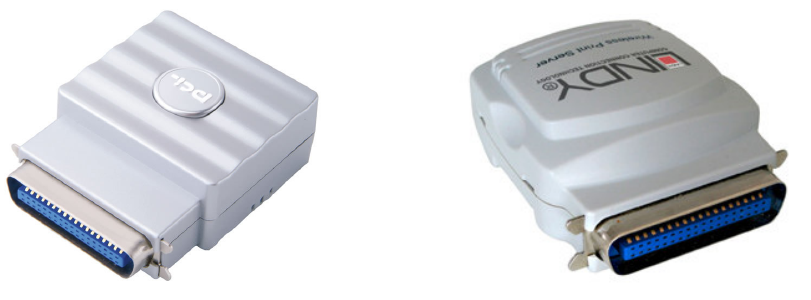
IEEE 802.11B Wireless Interface (Option)
This interface is supplied as an adaptor that plugs into the 36-pin Amphenol type connector
of the printer.
3.3V/2A power supply is prepared in MIP480 printer. If, when an external power supply is
needed for the module, this power supply can be used.
Standards Conformance
Wireless standard IEEE802.11b
Data Transfer Rate
1M/2M/5M/11Mbps auto-detection
Frequency Range
ISM band 2.4GHz
Communication Range
Line-of-sight max. distance :
Approximately 100m (indoors)
This may vary depending on conditions including
Obstacles between devices, signal quality, magnetic
fields, static electricity, electromagnetic interference,
software, operation system, reception sensitivity, and
antenna performance.
Recommended module
Planex Communications Inc LINDY Computer Connection Technology
Mini-PWF Print Server - 802.11b WLAN (1 Parallel)