Thomson Broadcast and Multimedia ULT-1K10K2 UHF Digital transmitter, for use with MediaFlo User Manual PREIMPAP
Thomson Broadcast & Multimedia, Inc. UHF Digital transmitter, for use with MediaFlo PREIMPAP
Contents
User Manual part 1

Di
5K2 DD, MEDIAFLO S
M
Operation and User Manual
gital Liquid Cooled UHF TV
Equipment
IRIUS
12089
45321648.01 108 B E
Numéro / Number Doc. Rev. Lan
g
u.
:
33
(
1
)
3
4.
90
.
3
2.
55
Checked
: hotline
@
thale
s
-bm.com 27/06/2006 9932 V2

Information contained is this document is confidential, is THOMSON property and cannot be disclosed in whatever form without prior written authorization of THOMSON.
Table of content
1. Exploitation .......................................................................................................6
1.1. Navigating the PCLwindows ......................................................................... 6
1.2. Where to find operational parameters........................................................ 11
1.2.1. Transmitter configuration parameters........................................................ 11
1.2.2. Transmitter operational parameters .......................................................... 12
1.2.3. Adjustable parameters............................................................................... 12
1.2.4. Measurements ........................................................................................... 13
1.2.5. Status conditions of main transmitter elements......................................... 14
1.3. Procedure for changing configuration parameters................................... 15
1.4. Procedure for inserting Ethernet network parameters ............................. 19
1.5. Procedure to activate "SNMP" or "WEB" agent ....................................... 21
1.6. Procedures for adjusting or changing operational parameters............... 23
1.6.1. Procedure to call the maintenance mode .................................................. 23
1.6.2. Procedure for adjusting the calibrated transmitter power.......................... 23
1.6.3. Procedure for adjusting the required transmitter power ............................ 24
1.6.4. Procedure for changing the modulator input ............................................. 25
1.6.5. Procedure for changing the configuration of the Adaptation parameters
(ALE and LUT)........................................................................................... 26
1.6.6. Procedure for changing the configuration parameters of the OLDC card .26
1.6.7. Procedure for changing the frequency of the RF synthesiser ................... 27
1.6.8. Procedure for changing ripple and shoulder threshold settings in
maintenance mode .................................................................................... 27
1.6.9. Procedure for changing the threshold settings of the OLDC card............. 28
1.6.10. Procedure for changing RF digital power threshold settings for triggering
alarm and fault signals............................................................................... 28
1.6.11. Procedures for changing quality thresholds .............................................. 29
1.6.12. Procedure for setting the time and the date .............................................. 29
1.7. Procedure for changing the PCL password............................................... 30
1.8. Procedures for changing a status condition or transmitter operating
mode .............................................................................................................. 31
1.8.1. Procedure for lock to unlock the PCL ........................................................ 31
1.8.2. Selection of transmitter operation mode.................................................... 32
1.8.3. Manuel change over of exciter .................................................................. 32
9932 V2
45321648.01 108 B E Checked ii
Numéro / Number Doc. Rev. Lan
g
u. 27/06/2006 Pa
g
e

Information contained is this document is confidential, is THOMSON property and cannot be disclosed in whatever form without prior written authorization of THOMSON.
1.8.4. Selection of exciter changeover mode ...................................................... 33
1.8.5. Selection of user interface ......................................................................... 33
1.9. Procedure for switching on and off ............................................................ 34
1.9.1. Switching on-air and switching off-air ........................................................ 34
1.9.2. Switching the reserve exciter on and off.................................................... 34
1.10. Procedure for adjusting PCL screen contrast ........................................... 35
1.11. Procedure for transmitter reset................................................................... 36
1.12. Procedure for using maintenance information.......................................... 37
1.12.1. Display of faults and status conditions ...................................................... 37
1.12.2. Access to logbook...................................................................................... 39
2. Use of commands and description of indicators .........................................40
2.1. Use and description of control panel screens........................................... 40
2.1.1. Outline........................................................................................................ 40
2.1.2. Installation windows................................................................................... 42
2.1.3. Warning windows....................................................................................... 53
2.1.4. "TRANSMITTER STATUS" window .......................................................... 57
2.1.5. "STATUS" window ..................................................................................... 61
2.1.6. "IDENTIFICATION" window....................................................................... 63
2.1.7. "MODULATOR IDENTIFICATION, Type I" window .................................. 65
2.1.8. "MODULATOR IDENTIFICATION, type II" window................................... 67
2.1.9. "CONTROL Level 1" window..................................................................... 69
2.1.10. "CONTROL MAINT Level 2" window for Maintenance mode.................... 72
2.1.11. "CONTROL MAINT Level 3" window for Maintenance mode.................... 74
2.1.12. "CONTROL MAINT Level 4" window for Maintenance mode (MODAP
version ONLY) ........................................................................................... 76
2.1.13. "CONTROL OPER Level 2" window for Normal Mode.............................. 78
2.1.14. "NUMERICAL VALUE" window ................................................................. 80
2.1.15. "RF LEVEL" window .................................................................................. 82
2.1.16. "REQUIRED POWER" window.................................................................. 85
2.1.17. "HOUR COUNTER" window...................................................................... 87
2.1.18. DATE & TIME" window.............................................................................. 89
2.1.19. "RF THRESHOLD" window ....................................................................... 91
2.1.20. "QUALITY THRESHOLD SETTINGS" window ......................................... 93
2.1.21. "COFDM or 8VSB PARAMETERS" window.............................................. 95
2.1.22. "FLO 1 PARAMETERS" window ............................................................... 98
2.1.23. "FLO 2 PARAMETERS" window ............................................................. 100
9932 V2
45321648.01 108 B E Checked iii
Numéro / Number Doc. Rev. Lan
g
u. 27/06/2006 Pa
g
e

Information contained is this document is confidential, is THOMSON property and cannot be disclosed in whatever form without prior written authorization of THOMSON.
2.1.24. "MISCELLANEOUS" window................................................................... 102
2.1.25. "LOGBOOK" window ............................................................................... 105
2.1.26. "EXCITER Level 1" window, or "EXCITER PANEL" window, MODAP
version ONLY .......................................................................................... 107
2.1.27. "EXCITER Level 2" window, MODAP version ONLY .............................. 111
2.1.28. "EXCITER Level 1" window, or "EXCITER PANEL" window, SIRIUS
version ONLY .......................................................................................... 113
2.1.29. "EXCITER Level 2" window, SIRIUS version ONLY ............................... 116
2.1.30. "FLO 1 MODULATOR" window .............................................................. 119
2.1.31. "FLO 2 MODULATOR" window .............................................................. 122
2.1.32. "COFDM MODULATOR" window............................................................ 124
2.1.33. "ADAPT PARAMETERS" window ........................................................... 126
2.1.34. "DASI STATUS" window.......................................................................... 129
2.1.35. "OLDC STATUS" window, MODAP version ONLY ................................. 132
2.1.36. "SETTINGS" window, SIRIUS version ONLY.......................................... 134
2.1.37. "RESERVE ADAPTATIVITY SETTINGS" window, SIRIUS version ONLY
136
2.1.38. "PREAMPLI SETTING" window, SIRIUS version ONLY......................... 138
2.1.39. "AGC SETTING" window, SIRIUS version ONLY ................................... 140
2.1.40. "LOCAL/IMAGE REJECT" window, SIRIUS version ONLY .................... 142
2.1.41. "10 MHz ADJUSTEMENT" window, SIRIUS version ONLY ................... 144
2.1.42. "LINEAR CORRECTION CALIBRATION" window, SIRIUS version ONLY
146
2.1.43. "SFN DELAY" window ............................................................................. 148
2.1.44. "MODULATOR CONFIG" window ........................................................... 150
2.1.45. "MODULATOR STATUS" window........................................................... 152
2.1.46. "MODULATOR - MIP" window................................................................. 154
2.1.47. "RF AMPLIFIERS" window, 6 current values (OPTIMUN / ULTIMATE
FAMILY) 155
2.1.48. "RF AMPLIFIERS" window, 8 current values (OPTIMUM FAMILY ONLY)
157
2.1.49. "PA LEVELS" window (OPTIMUM AND ULTIMATE FAMILIES ONLY) . 159
2.1.50. "AIR INTERLOCK" window (OPTIMUM AND ULTIMATE FAMILIES ONLY)
161
2.1.51. "LIQUIDE INTERLOCK" window (OPTIMUM AND ULTIMATE FAMILIES
ONLY) 164
2.1.52. "POWER SUPPLY" window (OPTIMUM AND ULTIMATE FAMILIES
ONLY) 166
2.1.53. "AFFINITY" window (AFFINITY FAMILY ONLY)..................................... 168
2.1.54. "GO HOME AND VIEW INSTALL. PARAMETERS" window .................. 170
2.1.55. "VIEW TRANSMITTER INTERFACE INSTALLATION PARAMETERS"
window 173
9932 V2
45321648.01 108 B E Checked iv
Numéro / Number Doc. Rev. Lan
g
u. 27/06/2006 Pa
g
e

Information contained is this document is confidential, is THOMSON property and cannot be disclosed in whatever form without prior written authorization of THOMSON.
2.1.56. "VIEW CABINET CONFIGURATION INSTALLATION PARAMETERS"
window 174
2.1.57. "VIEW ADAPT INSTALLATION PARAMETERS" window ...................... 175
2.1.58. "VIEW ETHERNET INSTALLATION PARAMETERS" window............... 177
2.1.59. Navigating the PCL windows................................................................... 179
2.2. Exciter, SIRIUS............................................................................................ 184
2.2.1. Front panel............................................................................................... 184
2.3. Local control panel..................................................................................... 186
2.3.1. Indicator lamps and message displays.................................................... 186
2.3.2. Adjustment controls ................................................................................. 186
2.3.3. Test points ............................................................................................... 186
2.4. TH860 CPU Card ......................................................................................... 187
2.4.1. Indicator lamps and message displays.................................................... 187
2.4.2. Controls.................................................................................................... 187
2.5. RF amplifier unit ......................................................................................... 188
2.5.1. Indicator lamps and message displays.................................................... 188
2.5.2. Test points ............................................................................................... 189
2.5.3. Adjustment controls ................................................................................. 189
2.6. Power supply unit....................................................................................... 190
2.6.1. Using the commands............................................................................... 190
2.6.2. Indicator lamps and message displays.................................................... 190
2.6.3. Test points ............................................................................................... 190
2.6.4. Adjustment controls ................................................................................. 190
2.7. 860 Cabinet Mains distribution ................................................................. 191
2.7.1. Indicator lamps and message displays.................................................... 191
2.7.2. Test points and adjustment controls........................................................ 191
9932 V2
45321648.01 108 B E Checked v
Numéro / Number Doc. Rev. Lan
g
u. 27/06/2006 Pa
g
e
Digital Liquid Cooled UHF
TV Equipment
Exploitation
Information contained is this document is confidential, is THOMSON property and cannot be disclosed in whatever form without prior written authorization of THOMSON.
1. Exploitation
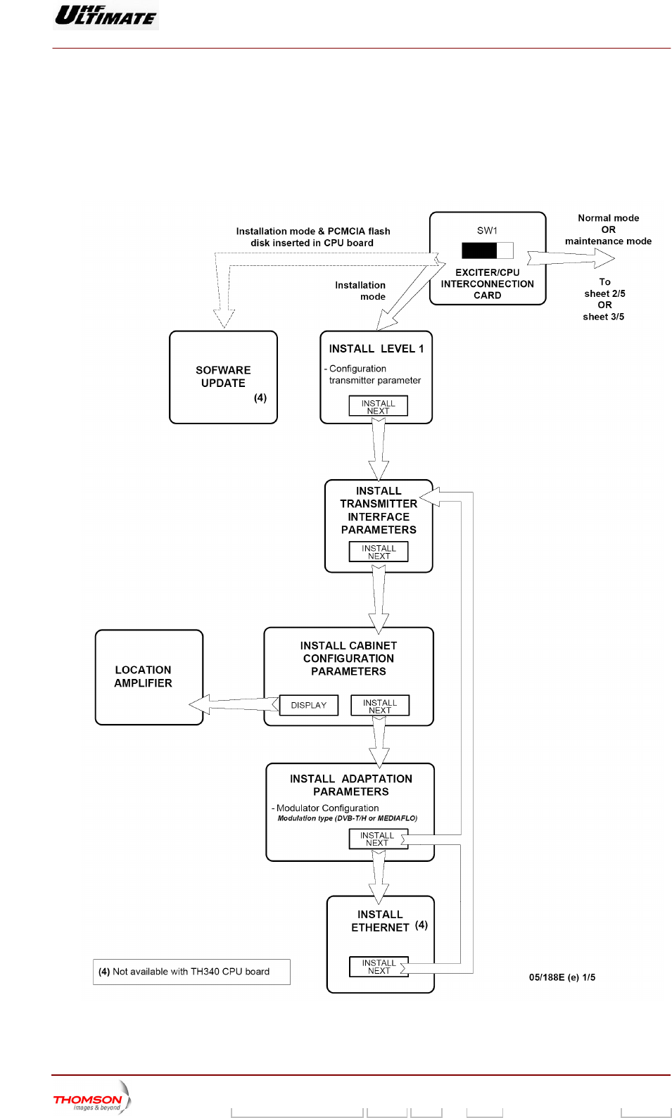
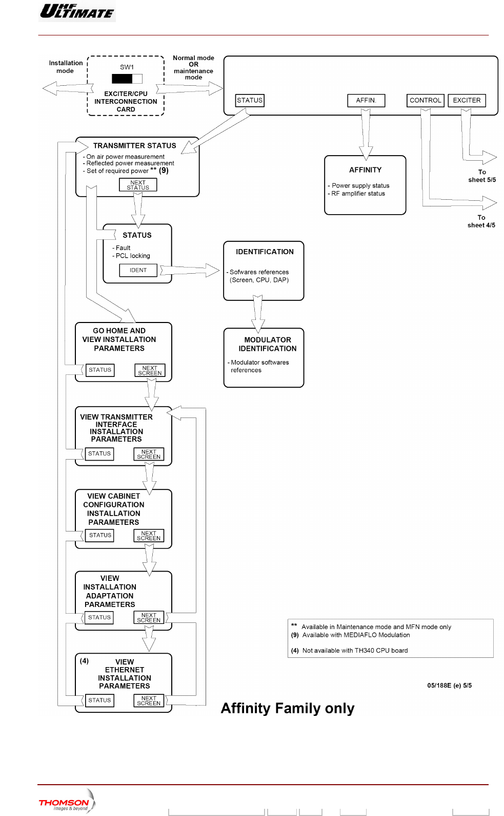
1.1. Navigating the PCLwindows
Figure 1 : Navigation in tactile screen windows (1/5)
9932 V2
45321648.01 108 B E Checked 6 / 192
Numéro / Number Doc. Rev. Lan
g
u. 27/06/2006 Pa
g
e
Digital Liquid Cooled UHF
TV Equipment
Exploitation
Information contained is this document is confidential, is THOMSON property and cannot be disclosed in whatever form without prior written authorization of THOMSON.
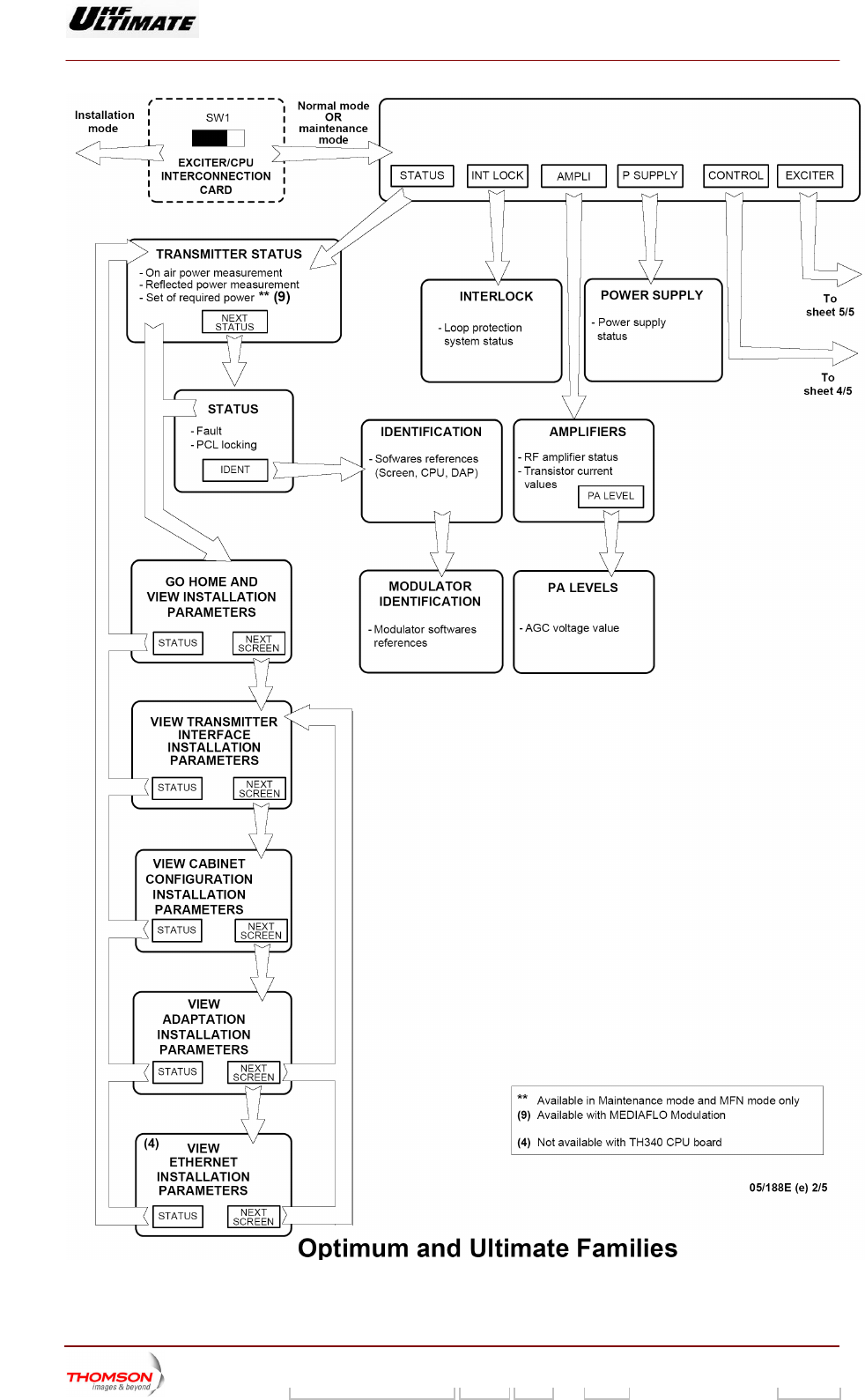
Figure 2 : Navigation in tactile screen windows (2/5)
9932 V2
45321648.01 108 B E Checked 7 / 192
Numéro / Number Doc. Rev. Lan
g
u. 27/06/2006 Pa
g
e
Digital Liquid Cooled UHF
TV Equipment
Exploitation
Information contained is this document is confidential, is THOMSON property and cannot be disclosed in whatever form without prior written authorization of THOMSON.
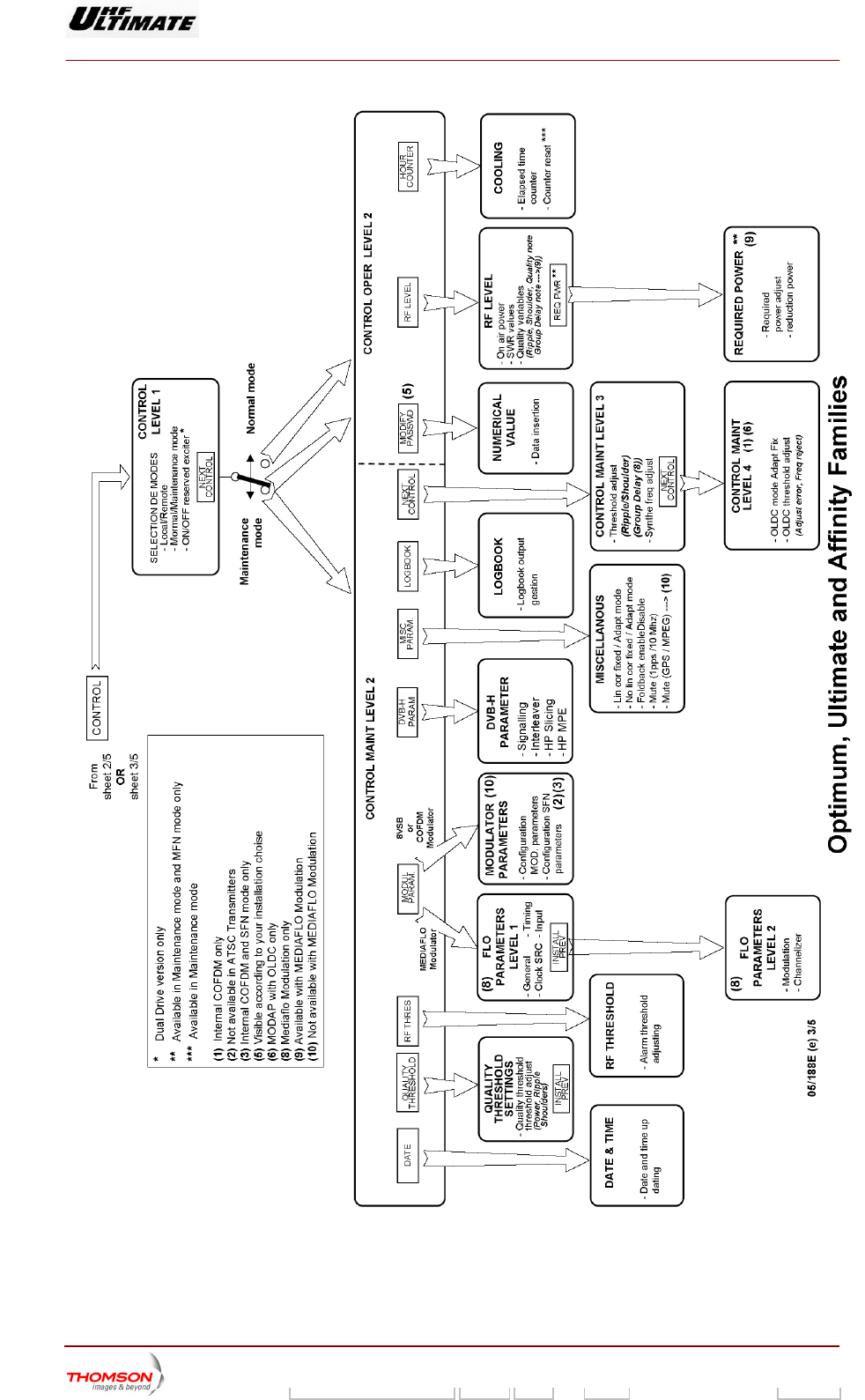
Figure 3 : Navigation in tactile screen windows (3/5)
9932 V2
45321648.01 108 B E Checked 8 / 192
Numéro / Number Doc. Rev. Lan
g
u. 27/06/2006 Pa
g
e
Digital Liquid Cooled UHF
TV Equipment
Exploitation
Information contained is this document is confidential, is THOMSON property and cannot be disclosed in whatever form without prior written authorization of THOMSON.
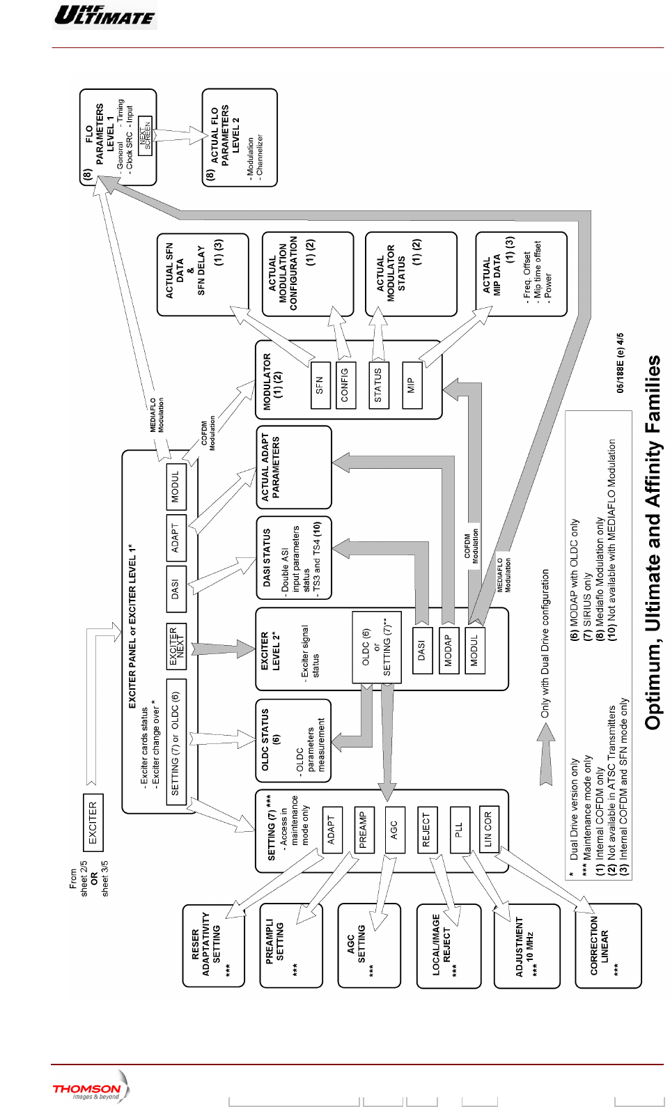
Figure 4 :: Navigation in tactile screen windows (4/5)
9932 V2
45321648.01 108 B E Checked 9 / 192
Numéro / Number Doc. Rev. Lan
g
u. 27/06/2006 Pa
g
e
Digital Liquid Cooled UHF
TV Equipment
Exploitation
Information contained is this document is confidential, is THOMSON property and cannot be disclosed in whatever form without prior written authorization of THOMSON.
F in tactile scigure 5 : Navigation reen windows (5/5)
9932 V2
45321648.01 108 B E Checked 10 / 192
Numéro / Number Doc. Rev. Lan
g
u. 27/06/2006 Pa
g
e
Digital Liquid Cooled UHF
TV Equipment
Exploitation
Information contained is this document is confidential, is THOMSON property and cannot be disclosed in whatever form without prior written authorization of THOMSON.
1.2. Where to find operational parameters
titles of the various PCL windows in wh h the various operational
para rator can be found. The commands for accessing these windows are
ven in other paragraph.
onfiguration parameters
The following tables give the
meters available to the ope
ic
gi
1.2.1. Transmitter c
PARAMETERS PCL WINDOWS
RF synthesiser frequency "INSTALLAT l 1" window
"GO HOME AND VIEW INSTALLATION
PARAMETERS" window
"CONTROL MAINT Level 3" window
ION PARAMETERS Leve
Frequency range (VHF/UHF)
Maximum power
Calibrated power
Cooling e of the transmitter typ
Transmitter type (S uble Drive, Passive
Reserve, Active Reser
imple Drive, Do
ve, N+1)
Modulation type of the transmitter (Analog /Digital)
Language selected
Type of display used (dB or %)
"INSTALLATION PARAMETERS Level 1" window
"GO HOME AND VIEW INSTALLATION
PARAMETERS" window
Type of remote operation (via serial link or hard wired)
Type of protocol operation for remote control (JBUS or
ASCII)
Transmitter Identification number with RS232 / RS 485
"TRANSMITT TALLATION
P w
"VIEW TRAN TALLATION
PARAMETERS " window
ER INTERFACE INS
ARAMETERS" windo
SMITTER INTERFACE INS
Type of bay used,
Current measurement number by amplifier unit
Amplifier number detected by cabinet
"CABINET CONFIGURATION PARAMETERS" window
"VIEW CABINET CONFIGU ION RATION INSTALLAT
PARAMETERS" window
Amplifier location in each cabinet "LOCAT ndow ION AMPLIFIER " wi
OLDC parameters (1)
DASI parameters (1)
ADAPT parameters
Type of modulator (COFDM / 8VSB)
"ADAPT INSTALLATION PARAMETERS" window
"VIEW ADA RS " window PT INSTALLATION PARAMETE
Web activation code
SNMP activation code
"ETHERNET INSTALLATION PARAMETERS" window
"VIEW ETHERNET METERS " INSTALLATION PARA
window
Network administrator configuration (IP address, sub-
net mask number)
Quality thresholds used for
parameters power, shoulder and
the notation of the
ripple
"QUALITY THRESHOLD SETTINGS" window
ATSC parameters***
COFDM parameters**
SFN data**
"COFDM or 8VSB PARAMETERS" window
Mediaflo modulator parameters ****
(General / Timing / Data SRC / Clock / Input)
(Modulation / channalizer)
"FLO 1 PARAMETERS" window and
"FLO 2 PARAMETERS" window
9932 V2
45321648.01 108 B E Checked 11 / 192
Numéro / Number Doc. Rev. Lan
g
u. 27/06/2006 Pa
g
e
Digital Liquid Cooled UHF
TV Equipment
Exploitation
Information contained is this document is confidential, is THOMSON property and cannot be disclosed in whatever form without prior written authorization of THOMSON.
PARAMETERS PCL WINDOWS
Mediaflo modulator parameters ****
Current ADAPT parameters "ADAPT PARAMETERS" window
COFDM current parameters** "MODULATOR CONFIGURATION" window
MediaFLO current parameters**** "FLO 1 MODULATOR" window and
"FLO 2 MODULATOR" window
SFN current delays** "SFN DELAYS" window
** Parameters used in DVB-T Transmitters only.
.
ransmitters only.
s
*** Parameters used in ATSC Transmitters only
**** Parameters used in Mediaflo T
(1) MODAP version only
1.2.2. Transmitter operational parameter
PARAMETERS PCL WINDOWS
Current operating mode (maintenance mode or normal "TRANSMITTER STATUS" window
"CONTROL" window
mode) "STATUS" window
PCL control – unlocked or locked
"Unlock" indicator lamp
"STATUS" window
Correction and transmitter operating mode (Fixed or
RBS or Mute)
"MISCELLANEOUS" window
adaptative / Mute or Not Mute / P
Last three faults to appear "STATUS" window
Selected User interface "CONTROL MAINT Level 1" window
Selected exciter *
Selected mode for exciter changeover *
Status of automatic exciter changeover * (Done, Not
done, impossible)
"TRANSMITTER STATUS" window
"EXCITER Level 1" window
Selected mode for the reflected (reserve) power control "TRANSMI TTER STATUS" window
Selected mode f r control gain of the transmitter (2) "AGC SEo TTING" window
"G tatus "GO HOME AND VIEW INSTALL TERS"
"Go Home" indicator lamp
O HOME" s ATION PARAME
window
Actual transmitter on-air time since going into service "HOUR COUNTER" window
*: Only in Double Drive Version
(2): SIRIUS version only
1.2.3. Adjustable parameters
PARAMETERS PCL WINDOWS
Amount of power reduction "REQUIRED POWER" window
Calibrated power "INSTALLATION indow PARAMETERS Level 1" w
High level Power alarm threshold «RF THRESHOLD» window
9932 V2
45321648.01 108 B E Checked 12 / 192
Numéro / Number Doc. Rev. Lan
g
u. 27/06/2006 Pa
g
e
Digital Liquid Cooled UHF
TV Equipment
Exploitation
Information contained is this document is confidential, is THOMSON property and cannot be disclosed in whatever form without prior written authorization of THOMSON.
PARAMETERS PCL WINDOWS
Low level Power alarm threshold
Fault power threshold
Ripple threshold for EXCITER correction
Shoulder threshold for EXCITER correction
Group Delay threshold for EXCITER correction (3)
"CONTROL MAINT Level 3" window
MGC gain value (2)
Limitor gain value (2)
"AGC SETTING" window
Adaptativity setting of the reserve exciter (2) "RESERVE ADAPTATIVITY SETTINGS" window
Calibrates of the linear correction feedback for exciter (2) "LINEAR CORRECTION CALIBRATION" window
Fault RF threshold fo r (2) "PREAMP S" window r RF preamplifie LIFIER SETTING
Cancel the level of the l
lateral band (2)
ocal frequency and of the unwanted GE REJECT" window "LOCAL/IMA
Adjust the value of the PLL 10Mhz frequency (2). STEMENT" window "10 MHz ADJU
Thresholds beyond which the OLDC performs a correction ROL MAINT Level 4" window
(1)
"CONT
Quality thresholds used for the notation of the parameters
power, shoulder and ripple
TTINGS" window "QUALITY THRESHOLD SE
Input signal type of the modulator
Clock type of the EXCITER
“COFDM or 8VSB PARAMETERS” window or
AMETERS“ window “FLO 1 PAR
PID number values (3)
Timing Values (3)
Modulation parameters values (3)
Channelizer parameters values (3)
ARAMETERS“ window and
TERS“ window
“FLO 1 P
“FLO 2 PARAME
(1) MODAP version only
(2) SIRIUS version only
(3) MediaFLO SIRIUS version only
1.2.4. Measureme ts n
PARAMETERS PCL WINDOWS
RF power
Reflected power
"TRANSMITTER STATUS" window
RF power
Reflected power
Antenna SWR
Shoulder level
Ripple level
Goup Delay level (3)
Transmitter gain
Overall quality assessment of the transmitter
"RF LEVEL" window
Reference AGC value (2)
Current AGC value (2)
"AGC SETTING" window
AGC voltages for power amplifiers “PA LEVELS” window
9932 V2
45321648.01 108 B E Checked 13 / 192
Numéro / Number Doc. Rev. Lan
g
u. 27/06/2006 Pa
g
e
Digital Liquid Cooled UHF
TV Equipment
Exploitation
Information contained is this document is confidential, is THOMSON property and cannot be disclosed in whatever form without prior written authorization of THOMSON.
PARAMETERS PCL WINDOWS
RF transistor currents in the power amplifiers "AMPLIFIERS" window
Central frequency rejection level (1) "OLDC PARAMETERS" window
I/Q amplitude error level (1) "OLDC PARAMETERS" window
(1) MODAP version only
(2) SIRIUS version only
(3) MediaF ly
1.2.5. Status conditions of main transmitter elements
LO SIRIUS version on
PARAMETERS PCL WINDOWS
Status of exciter cards "EXCITER PANEL" window
or
"EXCITER Level 2" window *
Status of reserve exciter (on or off) * "CONTROL" window
Status of exciter signals "EXCITER PANEL" window
"EXCITER Level 1" window *
or
Power amplifier status parameters "AMPLIFIERS" window
Sta "POWER SUPPLY" window tus of amplifier power supplies
Status of protection system surveillance devices "INTERLOCK" window
Status of the COFDM modulator** "MODULATOR STATUS" window
or
"MODULATOR CONFIGURATION" window
Status of the 8VSB modulator*** "MODULATOR CONFIGURATION" window
Status of the MediaFLO configuration for the modulator "MODULATOR FLO 1" window and "MODULATOR FLO 2"
window
Status of the ADAPT exciter "ADAPT PARAMETERS" window
Status of the DASI card “DASI STATUS” window
Status of the OLDC card (1) "OLDC STATUS" window
Status of the current gain control mode (2) "AGC SETTING" window
* : Only in Double Drive Version.
** : Parameters used in DVB-T Transmitters only.
(2) SIRIUS version only
(3) MediaFLO SIRIUS version only
*** : Parameters used in ATSC Transmitters only.
(1) MODAP version only
9932 V2
45321648.01 108 B E Checked 14 / 192
Numéro / Number Doc. Rev. Lan
g
u. 27/06/2006 Pa
g
e

Digital Liquid Cooled UHF
TV Equipment
Exploitation
Information contained is this document is confidential, is THOMSON property and cannot be disclosed in whatever form without prior written authorization of THOMSON.
1.3. Procedure for changing configuration parameters
The configuration parame ined in the "INSTALLATION PARAMETERS
Le and "TR e
PC mode.
Th parameters be
PARAMETERS" window of the
ters of the transmitter can be def
ANSMITTER INTERFACE INST L
of the ADAPT exciter can
PCL.
vel 1" window
L in installation
e configuration
A LATION PARAMETERS" window of th
defined in the "ADAPT INSTALLATION
Nota :
♦ MODAP Version
To set up a new parameter configuration of the modulator, the three corrections (ALE, LUT and OLDC) should be
the
only
set to FIXED mode. The control keys can be defined
" windows.
in the "MISCELLANEOUS" windows and "CONTROL
MAINT Level 4
♦ SIRIUS Ve
To set up a he two corrections (ALE, and LUT) should be set to
the FIXED
rsion only
new parameter configuration of the modulator,
mode
t
. The control keys can be defined in the "MI CELLANEOUS" windows. S
The configuration pa n be defined in the "ETHERNET INSTALLATION
PARAMETERS" win
DVB-T Transmitter c
♦ The configuration be defined in the "COFDM PARAMETTERS "
window of the PC
♦ The configuratio
of the PCL in maint ODE.
DVB-T/H Transmitter confi
♦ The configuration parameters of the COFDM can be
window and "DVB-H PARAMETTERS " window of the PC .
ediaFLO Transmit
♦ The configuration ERS"
window and " FLO CL in maintenance MODE.
The is confi
♦ "INSTALLATION A 1",
♦R
♦ "A TAL
♦ INSTA
♦ "COFDM and SFN PARAMETERS" (if internal modu t
windows or "FLO dows of the PCL.
rameters of the ETHERNET ca
dow of the PCL.
onfiguration only:
parameters of the COFDM can
L in maintenance MODE.
n parameters of the SFN can be defin
enance M
ed in the "COFDM PARAMETERS" window
guration only:
defined in the "COFDM PARAMETTERS "
L in maintenance MODE
M ter configuration only:
parameters of the MediaFLO can b
2 PARAMETTERS " window of the P
e defined in the "FLO 1 PARAMETT
transmitter gured in the:
P RAMETERS Level
"TRANSMITTE INTERFACE INSTALLATION PARAMETERS",
DAPT INS
"ETHERNET
LATION PARAMETERS",
LLATION PARAMETERS",
la or) windows or "8VSB PARAMETERS"
PARAMETERS" win
9932 V2
45321648.01 108 B E Checked 15 / 192
Numéro / Number Doc. Rev. Lan
g
u. 27/06/2006 Pa
g
e

Digital Liquid Cooled UHF
TV Equipment
Exploitation
Information contained is this document is confidential, is THOMSON property and cannot be disclosed in whatever form without prior written authorization of THOMSON.
The transmitter configuration can be defined via the tactile screen of PCL
ACTIONS RESULT
To call up the
"INSTALLATION
PARAMETERS
Level 1" window
a) Set switch SW1, situated in
the exciter/CPU
in
♦ The transmitter is switched to installation mode.
terconnection card on the
side of the sub-units behind
the CPU card, such that the
dot is visible.
♦ The "INSTALLATION PARAMETERS Level 1"
window appears on the PCL and displays the
current transmitter configuration parameters.
♦ Press reset button in front of CPU board.
Changing a
parameter:
♦ Press on the control keys corresponding
to the parameter to be changed and then
press repeatedly until the required
configuration appears.
♦ The names of the available configurations for the
parameter in question will appear one after the
other on the control keys.
Special case of changing the external
synthesiser frequency:
PORTANIM T :
fre
RF r, RF combiner,
new frequency.
Before validating a new synthesiser
quency, make sure that the settings of all
filters (ex. output RF filte
...) are consistent with the
♦ Press on the "FREQ SYNTHE (Hz)" key,
♦
s:
Enter the frequency value on the window
keyboard,
♦ Press "ENTER" to validate the entry.
Note
♦ The "NUMERICAL VALUE" window appears.
♦
The "INSTALLATION PARAMETERS Level 1"
window appears.
♦ The new frequency value is displayed in the
"FREQ SYNTHE (Hz)" key.
The value is displayed under the window title.
♦
To cancel an entry press the "CANCEL" key.
The f y must also be entered on the
thum . Alternatively, the thumb
wheels must be set to "0", except for the last
♦ The "INSTALLATION PARAMETERS Level 1"
window appears.
♦ The frequency value remains unchanged.
requenc
b wheels
one (LSB), which must be set to "1".
Validation of the new ♦ Check that the data displayed in the
window are correct,
♦ Press the "VALID" key.
♦
configuration
The transmitter stores the new configuration
parameters.
Cancelling the new
configuration
♦ Leave the installation mode without
touching the "VALID" key.
Leaving the
installation mode rconnection card, such
the
CPU board.
♦ et the CPU board
The system is initialised with the new status
♦ ER STATUS" window
♦ Set switch SW1, situated in the
exciter/CPU inte
that the dot is not visible and reset
Res
♦
and operational parameters.
The "TRANSMITT
appears and indicates that the system is in
normal operating mode.
The configuration parameters of the ADAPT exciter can be in the "ADAPT INSTALLATION
PARAMETERS" window of the PCL.
defined
ACTIONS RESULT
To call up the
"ADAPT
INSTALLATION
PARAMETERS"
window of the PCL
♦ Press "SCREEN NEXT" in the "INSTALL
CABINET CONFIGURATION
PARAMETERS " window.
♦ The "ADAPT INSTALLATION PARAMETERS"
window appears on the PCL and displays the
current DAP configuration parameters.
Changing a
parameter
♦ Press on the control keys corresponding
to the parameter to be changed and then
♦ The names of the available configurations for the
parameter in question will appear one after the
9932 V2
45321648.01 108 B E Checked 16 / 192
Numéro / Number Doc. Rev. Lan
g
u. 27/06/2006 Pa
g
e

Digital Liquid Cooled UHF
TV Equipment
Exploitation
Information contained is this document is confidential, is THOMSON property and cannot be disclosed in whatever form without prior written authorization of THOMSON.
ACTIONS RESULT
press repeatedly until the required
configuration appears.
other on the control keys.
Calls up the
"INSTALLATION
PARAMETERS
Level 1" for validation
♦ Pr ssively on "INSTALL NEXT"
in the "INSTALLATION PARAMETERS"
♦ The "INSTALLAT 1"
window appears on the PCL.
ess succe
windows.
ION PARAMETERS Level
L a neaving the install tio mode: When the PCL displays th
llows :
e "INSTALLATION PARAMETERS Level 1"
window, proceed as fo
ACTIONS RESULT
Leaving the
installation mode
♦ Press the valid key in the
"INSTALLATION PARAMETERS Level 1"
♦ h SW1, situated in the
♦ Reset the CPU board
arameters.
perational parameters.
window
Set switc
exciter/CPU interconnection card, such
that the dot is not visible.
♦ The transmitter stores the new configuration
p
♦ The system is initialised with the new status and
o
♦ The "STATUS" window appears and indicates
that the system is in normal operating mode.
The following operating quality threshold parameters of the ADAPT exciter can be defined in the
“QUALITY THRESHOLD SETTINGS” window of the PCL :
♦ ripple threshold,
♦ shoulder threshold,
♦. power threshold
A CTIONS RESULT
To call up the
of the PCL
♦ Press "QUALITY THRESHOLD" in the ♦ The “QUALITY THRESHOLD SETTINGS”
“QUALITY
THRESHOLD
SETTINGS” window
"CONTROL MAINT Level 2" window. window appears on the PCL and displays
the current threshold value.
To change a
rameter valupa e
♦
Note
♦ Press on the control keys of the
parameter to be changed,
Enter the required value on the window
keyboard,
♦ Press "ENTER" to validate the entry.
:
♦ The "CONTROL MAINT Level 2" window
appears.
♦ The new value is displayed on the parameter
control keys.
♦ The "NUMERICAL VALUE" window appears.
The value is displayed under the window title. ♦
To cancel an entry press the "CANCEL" key. ♦ The "CONTROL MAINT Level 2" window
appears.
♦ The value remains unchanged.
9932 V2
45321648.01 108 B E Checked 17 / 192
Numéro / Number Doc. Rev. Lan
g
u. 27/06/2006 Pa
g
e

Digital Liquid Cooled UHF
TV Equipment
Exploitation
Information contained is this document is confidential, is THOMSON property and cannot be disclosed in whatever form without prior written authorization of THOMSON.
The configuration parameters of the COFDM and SFN can be defined in the "COFDM
PARAMETERS" window of the PCL in maintenance mode.
These parameters are used in DVB-T Transmitters only.
ACTIONS RESULT
To call up the
"COFDM
♦ Press "MO
MAINT Level 2"
PARAMETERS"
window of the PCL
DUL" in the "CONTROL
window.
♦ The "COFDM PARAMETERS" window
appears on the PCL and displays the
current COFDM configuration parameters.
Changing a COFDM ♦ Press on the co
parameter
ntrol keys corresponding
to the parameter to be changed and then
press repeatedly until the required
configuration appears.
♦ Press the valid key for validation the new
♦ The names of the available configurations
for the parameter in question will appear
one after the other on the control keys.
entry
Changing a SFN
parameter
♦
ue on the window
keyboard
♦
♦ The value is displayed under the window title.
Press on the control key corresponding to
the parameter to be changed
♦ Enter the required val
Press "ENTER" to validate the entry. ♦
keys.
♦ The "NUMERICAL VALUE" window appears.
The "COFDM PARAMETERS" window appears.
The value is displayed on the parameter control
T
and "F ARAMET CL in maintenance mode.
he configuration p
LO2 P
arameters of the MediaFLO can be de
ERS" window of the P
fined in the "FLO1 PARAMETERS" window
These parameters are used in MediaFLO Transmitters only.
ACTIONS RESULT
To call up the "FLO1
PARAMETERS"
window of the PCL
UL" in the "CONTROL ♦ ARAMETERS" window appears on
the PCL and displays the current MediaFLO
configuration parameters (GENERAL / DATA
SRC / Clock / TIMING / INPUT).
♦ Press "MOD
MAINT Level 2" window.
The "FLO1 P
To call up the "FLO2
PARAMETERS"
window of the PCL
♦ ♦ The "FLO2 PARAMETERS" window appears on
the PCL and displays the current MediaFLO
configuration parameters. (MODULATION /
CHANNELIZER)
Press "NEXT SCREEN" in the "FLO1
PARAMETERS" window.
Changing a FLO
parameter
tedly until the required
configuration appears. other on the control keys.
♦ Press on the control keys corresponding
to the parameter to be changed and then
press repea
♦ Press the valid key for validation the new
entry
♦ The names of the available configurations
for the parameter in question will appear
one after the
9932 V2
45321648.01 108 B E Checked 18 / 192
Numéro / Number Doc. Rev. Lan
g
u. 27/06/2006 Pa
g
e

Digital Liquid Cooled UHF
TV Equipment
Exploitation
Information contained is this document is confidential, is THOMSON property and cannot be disclosed in whatever form without prior written authorization of THOMSON.
1.4. Procedure for inserting Ethernet network parameters
The following parameters of the Ethernet network can be inserted in the “ETHERNET INSTALLATION
PARAMETERS” window L :
♦ IP f the a
♦ Sub-net mask numb
♦ IP address of the a
of the PC
address o tr nsmitter,
er,
g teway.
ACTIONS RESULT
To call up the
"INSTALLATION
PARAMETERS
Level 1" window
♦ Set switch SW1, situated in the
exciter/CPU interconnection card on the
side of the sub-units behind the CPU
card, such that the dot is visible.
♦ Reset the CPU Board
♦ The transmitter is switched to installation mode.
♦ The "INSTALLATION PARAMETERS Level 1"
window appears on the PCL and displays the
current transmitter configuration parameters.
To call up the
"ETHERNET
INSTALLATION
PARAMETERS"
window of the PCL
♦ Press "INSTALL NEXT" in the
"TRANSMITTER INTERFACE
INSTALLATION PARAMETERS",
"CABINET CONFIGURATION
PARAMETERS" and "INSTALLATION
ADAPT PARAMETERS" window.
♦ The "ETHERNET INSTALLATION
PARAMETERS" window appears on the PCL and
displays the current configuration parameters.
To insert a parameter
value
♦ Press on the control keys of the
parameter to be inserted,
♦ Enter the required value on the window
keyboard,
♦ Press "ENTER" to validate the entry
IMPORTANT :
• The network parameter must be
furnished by your network
administrator.
• Setting bad parameter disturbs the
network.
♦ The "NUMERICAL VALUE" window appears.
♦ The value is displayed under the window title.
♦ The "INSTALLATION PARAMETERS" window
appears. The value is displayed on the parameter
control keys.
Note:
♦ To cancel and entry press the "CANCEL"
key.
♦ The "INSTALLATION PARAMETERS"
window appears. The value remains
unchanged.
Calls up the
"INSTALLATION
PARAMETERS
Level 1" for validation
♦ Press "INSTALL NEXT" in the
"ETHERNET INSTALLATION
PARAMETERS" window.
♦ The "INSTALLATION PARAMETERS Level 1"
window appears on the PCL.
9932 V2
45321648.01 108 B E Checked 19 / 192
Numéro / Number Doc. Rev. Lan
g
u. 27/06/2006 Pa
g
e

Digital Liquid Cooled UHF
TV Equipment
Exploitation
Information contained is this document is confidential, is THOMSON property and cannot be disclosed in whatever form without prior written authorization of THOMSON.
Leaving the installation mode: When the PCL displays the "INSTALLATION PARAMETERS Level 1"
window, proceed as follows :
ACTIONS RESULT
Leaving the
installation mode
♦ Press the valid key in the
"INSTALLATION P
♦ The transmitter stores the new configuration
ARAMETERS Level 1"
window
♦ Set switch SW1, situated in the
exciter/CPU interconnection card, such
that the dot is not visible.
parameters.
♦ The system is initialised with the new status and
operational parameters.
♦ The "STATUS" w pears and indicates
♦ Reset the CPU board
indow ap
that the system is in normal operating mode.
9932 V2
45321648.01 108 B E Checked 20 / 192
Numéro / Number Doc. Rev. Lan
g
u. 27/06/2006 Pa
g
e

Digital Liquid Cooled UHF
TV Equipment
Exploitation
Information contained is this document is confidential, is THOMSON property and cannot be disclosed in whatever form without prior written authorization of THOMSON.
1.5. Procedure to activate "SNMP" or "WEB" agent
Each option is associated with an activation code. Each code is single and associated with one CPU
board. The identification r of the CPU board is given on the “ET INSTALLATION
PARAMETERS” win o
W (
numbe HERNET
d w. With this number you can get the
ask for THALES).
activation code of the SNMP agent and/or
EB agent option
ACTIONS RESULT
To call up the
"INSTALLATION
PARAMETERS
Level 1" window
situated in the
ction card on the
side of the sub-units behind the CPU
card, such that the dot is visible.
♦ Reset the CPU board
♦ e.
♦ The "INSTALLATION PARAMETERS Level 1"
window appears on the PCL and displays the
current transmitter configuration parameters.
♦ Set switch SW1,
exciter/CPU interconne
The transmitter is switched to installation mod
To call up the
"ETHERNET
INSTALLATION
PARAMETERS"
window of the PCL
♦ Press "INSTALL NEXT" in the
"TRANSMITTER INTERFACE
INSTALLATION PARAMETERS",
"CABINET CONFIGURATION
PARAMETERS" and "INSTALLATION
ADAPT PARAMETERS" window.
♦ The "ETHERNET INSTALLATION
PARAMETERS" window appears on the
PCL and displays the current configuration
parameters.
Set the Ethernet
network parameters
♦ IP address of the transmitter,
♦ Sub-net mask number,
♦ IP address of the gateway.
♦ Refer to procedure § “Procedure for
inserting Ethernet network parameters”
IMPORTANT :
• The NetWare parameters must be
furnished by your network
administrator.
• Setting bad parameter disturbs the
network.
To insert the
activation code
♦ Press on the control keys of the code to
be inserted,
♦ Enter the required value on the window
keyboard,
♦ Press "ENTER" to validate the entry.
IMPORTANT :
• Enter a bad code leads the control
keys display to cone back to “0”.
♦ The "NUMERICAL VALUE" window appears.
♦ The value is displayed under the window title.
♦ The "INSTALLATION PARAMETERS" window
appears.
♦ The value is displayed on the control keys.
♦ The "INSTALLATION PARAMETERS" window
appears.
Note:
To cancel and entry press the "CANCEL"
key.
♦ The value remains unchanged
Calls up the
"INSTALLATION
PARAMETERS
Level 1" for validation
♦ Press "INSTALL NEXT" in the
"ETHERNET INSTALLATION
PARAMETERS" window.
♦ The "INSTALLATION PARAMETERS Level 1"
window appears on the PCL.
9932 V2
45321648.01 108 B E Checked 21 / 192
Numéro / Number Doc. Rev. Lan
g
u. 27/06/2006 Pa
g
e

Digital Liquid Cooled UHF
TV Equipment
Exploitation
Information contained is this document is confidential, is THOMSON property and cannot be disclosed in whatever form without prior written authorization of THOMSON.
Leaving the installation mode: When the PCL displays the "INSTALLATION PARAMETERS Level 1"
window, proceed as follows :
ACTIONS RESULT
Leaving the
installation mode
♦ Press the valid key in the
"INSTALLATION PARAMETERS Level 1"
windo
♦ The transmitter stores the new configuration
parameters.
w
xciter/CPU interconnection card, such
visible.
♦ Reset the CPU board
♦ The system is initialised with the new status and
♦ The "STATUS" window appears and indicates
that the system is in normal operating mode.
♦ Set switch SW1, situated in the
e
that the dot is not
operational parameters.
9932 V2
45321648.01 108 B E Checked 22 / 192
Numéro / Number Doc. Rev. Lan
g
u. 27/06/2006 Pa
g
e

Digital Liquid Cooled UHF
TV Equipment
Exploitation
Information contained is this document is confidential, is THOMSON property and cannot be disclosed in whatever form without prior written authorization of THOMSON.
1.6.
1.6.1. Procedure to call the maintenance mode
Adjustments or change ly intenance mode and
when the PCL is unlocked.
s locked (disabled), unlock it (refer to procedure for unlocking the PCL, § procedure
ck or unlock the PCL.
Procedures for adjusting or changing operational parameters
s to operational parameters can on
be carried out in ma
If the PCL screen i
lo
ACTIONS RESULT
To call up the
"CONTROL" window
♦ Press the "CONTROL" key. ♦ The PCL "CONTROL
appears.
of the PCL:
Level 1" window
If the transmitter is in
normal mode, switch
to maintenance mode
♦ Press on the «MODE» key in the PCL
"C Level 1" window.
♦ The "NORMAL" message window above the
«MODE» key is replaced by a flashing "MAINT
MODE" message window.
♦ ystem is now in maintenance mode.
ONTROL
♦ Press the "VALID" key.
♦ The "MAINT" message window stops flashing and
remains lit.
The s
To call up the
"CONTROL MAINT
Level 2" window
♦ NTROL LEVEL 2" in the
"CONTROL Level 1" window.
♦ ROL MAINT Level 2" window
Press "CO The "CONT
appears.
1.6.2. Procedure for adjusting the calibrated transmitter power
Adjustments or changes to ca power can only be carried out in installation mode.
The calibrated trans the “ INSTALLATION PARAMETERS Level 1” window of
the PCL. The RF
according to RF feedba
librated transmitter
mitter can be inserted in
probes of the transmitter are adjuste
ck input value.
d depending on required power value and
ACTIONS CONSEQUENCES
To call up the
"INSTALLATION
PARAMETERS
Level 1" window
♦
interconnection card on the
side of the sub-units behind the CPU
♦
♦ hed to installation mode.
1"
Set switch SW1, situated in the
exciter/CPU
card, such that the dot is visible,
Reset CPU board.
The transmitter is switc
♦ The "INSTALLATION PARAMETERS Level
window appears on the PCL and displays the
current transmitter configuration parameters.
Select the required
power value
♦ In the "INSTALLATION PARAMETERS
LEVEL 1" window, press on the "CAL
PWR" key.
To insert a parameter
value
♦ Enter the calibrated value on the window
keyboard,
♦ Press "ENTER" to validate the entry.
Note:
♦ The value is displayed under the window title.
♦ The "INSTALLATION PARAMETERS" window
appears.
♦ The "NUMERICAL VALUE" window appears.
To cancel an entry press on the "EXIT" key. ♦ The "INSTALLATION PARAMETERS Level 1"
window reappears.
♦ The calibrated power value remains unchanged
9932 V2
45321648.01 108 B E Checked 23 / 192
Numéro / Number Doc. Rev. Lan
g
u. 27/06/2006 Pa
g
e

Digital Liquid Cooled UHF
TV Equipment
Exploitation
Information contained is this document is confidential, is THOMSON property and cannot be disclosed in whatever form without prior written authorization of THOMSON.
ACTIONS CONSEQUENCES
Leaving the
installation mode
♦ Press the valid key in the
"INSTALLATION PARAMETERS Level 1"
window,
♦ The transmitter stores the new configuration
parameters.
♦ Set switch SW1, situated in the
exciter/CPU interconnection card, such
that the dot is not visible,
♦ The system is initialised with the new status and
operational parameters.
♦ Reset the CPU board.
♦ The "STATUS" window appears and indicates
that the system is in normal operating mode.
1.6.3. Pro
Having alre d n maintenance mode and also having unlocked the PCL and
called up the
cedure for adjusting the required transmitter power
a y configured the system i
"TRANSMITTER STATUS" window, carry out the following operations :
ACTIONS RESULT
Select the required ♦ In NSMITTER STATUS" ♦ The "REQUIRED indow appears.
power value
the "TRA
window, press on the "REQUIR POWER"
key ♦
POWER" w
The current value is displayed under the window
title.
1 - To insert the
required p er value
♦ Enter the required value on the window
♦
P
ow keyboard,
Press "ENTER" to validate the entry.
IM ORTANT :
Range of variation:
0.25 *Cal Pwr < REQ Pwr < 1.12 Cal
Pwr and
REQ Pwr < MAX Pwr
ncelling the selection: Ca
nder the
The system activates the new power reduction
value.
♦ The new current value is displayed u
window title
♦
QUIRED ♦
♦ res the new power reduction
♦ Press “CANCEL” key in the "RE
POWER" window.
The "TRANSMITTER STATUS" or "RF LEVEL”
window appears.
The system igno
value.
2 - Select the
reduction value:
♦ In the "POWER REQUIRED" window,
y successively
uction value is
displayed
♦ values of power reduction appear
the
♦ m activates the new power reduction
value.
required power press on the "x dB" ke
until the required power red
♦ Press the "ENTER" key for Validation of
selection:
Cancelling the selection:
The available
successively on the key. he key flashes until
selection is validated.
♦ The "x DB" key stops flashing and remains lit.
The syste
♦ ♦ The "TRANSMITTER STATUS" or "RF LEVEL”
window appears.
♦ The system ignores the new power reduction
value.
Press “CANCEL” key in the "REQUIRED
POWER" window.
9932 V2
45321648.01 108 B E Checked 24 / 192
Numéro / Number Doc. Rev. Lan
g
u. 27/06/2006 Pa
g
e

Digital Liquid Cooled UHF
TV Equipment
Exploitation
Information contained is this document is confidential, is THOMSON property and cannot be disclosed in whatever form without prior written authorization of THOMSON.
1.6.4. for changing the modulator input
eady configured the system in local control, maintenance mode, and also having unlocked
d called up the “COFDM PARAMETERS” window.
Procedure
This procedure describes how to change the input signal type of the modulator unit and the clock type
of ADAPT exciter in DVB-T Transmitter only.
Having alr
the PCL an
Note :
♦ MODAP Version only
To set up a new parameter configuration of the modulator, the three corrections (ALE,
LUT and OLDC) should be set to the FIXED mode. The control keys can be defined in
the "MISCELLANEOUS" window and "CONTROL MAINT Level 4" window.
♦ SIRIUS Version only
To set up a rameter configuration of the modulator, the ections (ALE, and new pa two corr
LUT) should be set to the FIXED mode.
LANEOUS" window.
The control keys can be defined in the
EL"MISC
ACTIONS RESULT
Set the corrections of
A
♦ ing the
s of the ADAPT
In FIXE position, the correction parameters are not
AL
DAPT exciter to
FIXE MODE :
Refer to procedure for chang
configuration parameter
exciter.
continuously adjusted.
E and LUT corrections are FIXE MODE.
♦ Refer to procedure for changing the
configuration parameters of the OLDC
card (Available in MODAP version only).
♦ OLDC correction is in FIXE MODE.
Select the required
parameters input
♦ In the “COFDM PARAMETERS” window,
press on the “DATA XXXX” key
♦ The available values of input parameters
successively on the key.
successively until the required input
signal type is displayed.
♦ In the “COFDM PARAMETERS” window,
press on the “CLOCK XX” key
♦ The key flashes until the selection is validated.
successively until the required clock type
is displayed.
appear
Validation of selection ♦ Press the “VALID” key. ♦ The “DATA” o
and remains lit.
r “LOCK” keys stops flashing
♦ The system activates the new input
parameter
Cancelling the
selection
♦ Press the “CANCEL” key. ♦ The system ignores the new input parameter.
Set the corrections of
ADAPT exciter to
ADAPTIVE MODE
♦ Refer to changing the configuration
parameters of the ADAPT exciter.
♦ ALE and LUT corrections are ADAPT
MODE.
♦ Refer to for changing the configuration
parameters of the OLDC card (Available
in MODAP version only)..
♦ OLDC correction is in ADAPT MODE.
9932 V2
45321648.01 108 B E Checked 25 / 192
Numéro / Number Doc. Rev. Lan
g
u. 27/06/2006 Pa
g
e
Digital Liquid Cooled UHF
TV Equipment
Exploitation
Information contained is this document is confidential, is THOMSON property and cannot be disclosed in whatever form without prior written authorization of THOMSON.
1.6.5. Procedure for changing the configuration of the Adaptation parameters (ALE
S card (SIRIUS
ersion).
Summary
and LUT)
This procedure provides for changing the type of linearity "ALE" and non linearity "LUT" signal
correction (fixed or adaptive) performed by the DAP card (MODAP version) or T
v
In fixed position, the corre meters are not continuously adjusted.
Hav g unlocked
the PCL and called up ELLANEOUS" window (refer to procedures which are necessary prior
to adjusting or changin
ction para
ing already configured the system in local control, main
the "MISC
tenance modes, and also havin
g an operational parameter), carry out the following operations :
ACTIONS RESULT
To change the type
of correction
(or
"FIXED MODE") in the
"MISCELLANEOUS" window.
♦ The control keys flashes and displays the new
selection in reverse video.
♦ Press "N. LIN COR ADAPTIVE MODE"
(or "FIXED MODE") in the
“MISCELLANEOUS” window.
♦ Press " LIN COR ADAPTIVE MODE" ♦ The control keys flashes and displays the new
selection in reverse video.
Validation of
selection
♦ Press the "VALID" key. ♦ The control keys label stops flashing and display
the new selection picked up the system in no
s
rmal
video.
1.6.6. Procedure for changing the configuration parameters of the OLDC card
Note : T edure is achieve in COFDM MODAP version only his proc
This procedure provides for changing the type of signal correction (fixed or adaptive) performed by the
OLDC card.
Remember
In fixed position, the correction parameters are not continuously adjusted.
Having already configured the system in local control, maintenance modes, and also having unlocked
e PCL and called up the "CONTROL MAINTENANCE Level 4" window (refer to procedures which
cessary prior to adjusting or changing an operational parameter), carry out the following
operations :
th
are ne
ACTIONS RESULT
To change the type of ♦ ELECT MODE" in the
♦ The message window above the control
correction
Press "S
"CONTROL MAINT Level 4" window keys flashes while displaying the newly
selected operating mode (OLDC ADAPT or
OLDC FIXE).
Val on
ly
selected operating mode.
idation of selecti ♦ Press the "VALID" key. ♦ The message window above the "SELECT
dMODE" control keys stops flashing an
remains lit while displaying the new
Cancelling the
selection
♦ Press the "CANCEL" key. ♦ The message window above the "SELECT
MODE" control keys stops flashing and
remains lit while displaying the operating
mode which had been previously selected.
9932 V2
45321648.01 108 B E Checked 26 / 192
Numéro / Number Doc. Rev. Lan
g
u. 27/06/2006 Pa
g
e

Digital Liquid Cooled UHF
TV Equipment
Exploitation
Information contained is this document is confidential, is THOMSON property and cannot be disclosed in whatever form without prior written authorization of THOMSON.
1.6.7. Procedure for changing the frequency of the RF synthesiser
Having a so having unlocked the PCL and lready configured the system in maintenance mode and al
called up the "CONTROL MAINT Level 3" window (refer to procedures which are necessary prior to
adjusting or changing an operational parameter), carry out the following operations :
ACTIONS CONSEQUENCES
To change the
frequency
♦ In the "CONTROL MAINT Level 3" The "NUMERICAL VALUE" appears.
window, press on the "FREQ SYNTHE
(Hz)" key.
♦ Enter the f ncy value on the window
k
Be synthesiser
F
...) are consistent with the new frequency.
♦ The value is displayed under the window title.
reque
eyboard.
IMPORTANT :
fore validating a new
frequency, make sure that the settings of all
R filters (ex. output RF filter, RF combiner,
Validation of selection ♦ Press "ENTER" to validate the entry.
The "CONTROL MAINT Level 3" window reappears.
The new frequency value is displayed in the "FREQ
SYNTHE (Hz)" key.
Cancelling the
selection
♦ Press the "CANCEL" key.
♦ The frequency value remains unchanged.
♦ The "CONTROL MAINT" window reappears.
1.6.8. ripple and shoulder threshold settings in maintenance
oulder thresholds beyond which the ADAPT
rocedures which
re necessary prior to adjusting or changing an operational parameter), carry out the following
perations :
Procedure for changing
mode
This procedure describes how to change the ripple and sh
exciter performs a correction.
Having already configured the system in local control, maintenance modes, and also having unlocked
the PCL and called up the "CONTROL MAINTENANCE Level 3" window (refer to p
a
o
ACTIONS RESULT
Changing thr ♦ Press on the message window of the
♦ on the window
The "NUMERICAL VALUE" window appears. esholds
threshold to be changed.
Enter the required value
keyboard.
The value is displayed under the window title.
Validation of selection ♦ o validate the entry. Th TROL MAINT Level 3" window reappears.
Press "ENTER" t e "CON
The new threshold value is displayed on the
corresponding key.
Cancelling the ♦ Press the "CANCEL" key. Th evel 3" window reappears.
.
selection
e "CONTROL MAINT L
♦ The threshold value remains unchanged
9932 V2
45321648.01 108 B E Checked 27 / 192
Numéro / Number Doc. Rev. Lan
g
u. 27/06/2006 Pa
g
e

Digital Liquid Cooled UHF
TV Equipment
Exploitation
Information contained is this document is confidential, is THOMSON property and cannot be disclosed in whatever form without prior written authorization of THOMSON.
1.6.9. Procedure for changing the threshold settings of the OLDC card
Note : This procedure is achieve in COFDM MODAP version only
This procedure describes how to change the central frequency rejection threshold and the I/Q
amplitude error threshold beyond which the OLDC card performs a correction.
Having already configured the system in local control, maintenance modes, and also having unlocked
the PCL and called up the "CONTROL MAINTENANCE Level 4" window (refer to procedures which
cessary prior to adjusting or changing an operational parameter), carry out the followinare ne g
operations :
ACTIONS RESULT
Changing thresholds ♦ Press on the message window of the The "NUMERICAL VALUE"
threshold to be changed.
♦ Enter the required value on the window
window appears.
The value is displayed under the window title.
keyboard.
Vali on ♦ date the entry. h
The new threshold value is displayed on the
dation of selecti Press "ENTER" to vali T e "CONTROL MAINT Level 4" window reappears.
corresponding key.
Cancelling the
selection
♦ y. he "CONTROL MAINT Level 4" window reappears.
Press the "CANCEL" ke T
♦ The threshold value remains unchanged.
1.6.10. Procedure for changing RF digital power r
alarm and fault signals
This p scribes how to change digital power thre ings for triggering alarm and fault
signals on the PCL (three-colour "Alarm" indicator lamp).
aving already configured the system in maintenance mode and also having unlocked the PCL and
called up the "CONTROL MAINT Level 2" window (refer to procedures which are necessary prior to
perations :
th eshold settings for triggering
rocedure de shold sett
H
adjusting or changing an operational parameter), carry out the following o
ACTIONS RESULT
To call up the «RF ♦ In the "CONTROL MAINT Level 2"
♦ The «RF THRESHOLD»
THRESHOLD»
window of the PCL
wi w, press on the "RFTHRES" key.
window appears.
ndo
Changing thresholds ♦ Press on the message window of the
threshold to be changed.
♦ Enter the required value on the window ♦ r the window
keyboard.
♦ The "NUMERICAL VALUE" window appears.
The value is displayed unde
title.
Validation of séle ♦ ♦
♦
ding key.
ction Press "ENTER" to validate the entry. The «RF THRESHOLD» window reappears.
The new threshold value is displayed on the
correspon
Cancelling the
selection
♦ Press the "CANCEL" key. ♦ The «RF THRESHOLD» window reappears.
♦ The threshold value remains unchanged.
9932 V2
45321648.01 108 B E Checked 28 / 192
Numéro / Number Doc. Rev. Lan
g
u. 27/06/2006 Pa
g
e

Digital Liquid Cooled UHF
TV Equipment
Exploitation
Information contained is this document is confidential, is THOMSON property and cannot be disclosed in whatever form without prior written authorization of THOMSON.
1.6.11. Procedures for changing quality thresholds
(in dB) from a set point before the
♦ The set point (Shoulder, Ripple) is the parameter threshold beyond which the ADAPT exciter
performs a correctio points can be defined in the "CONTR window.
The power set p
operator in the "INS "
Having already configu mode and also having unlocked the PCL and
c N
adju in a
The quality threshold is the maximum permissible deviation
occurrence of a major fault (overall quality assessment of 13/20), which produces a transmitter
changeover in an N+1 or Passive Reserve system. In SD or DD systems, no changeover is
performed.
n. The set OL MAINT Level 3"
♦oint is the calibrated RF power of the
TALLATION PARAMETERS Level 1
red the system in maintenance
transmitter, it is fixed and is available to the
window.
alled up the "CO
sting or chang
TROL MAINT Level 2" window (refer
g n operational parameter), carry out the following o
to procedures which are necessary prior to
perations :
ACTIONS RESULT
To call up the
"QUALITY
THRESHOLD
SETTINGS" window
♦ In the "CONTROL MAINT Level 2"
window, press on the "QUALITY
THRESHOLDS" key.
♦ The "QUALITY THRESHOLD SETTINGS"
window appears on the PCL and displays the
current quality thresholds.
Changing quality
thresholds
♦ message window of the
♦ required value on the window
w title.
Press on the
threshold to be changed.
Enter the
keyboard.
The "NUMERICAL VALUE" window appears.
♦ The value is displayed under the windo
Validation of selection ♦ ER" to validate the entry. ♦ ALITY THRESHOLD SETTINGS"
♦
Press "ENT The "QU
window reappears.
The new threshold value is displayed on the
corresponding key.
Cancelling the
selection
h
rea
♦ Press the "CANCEL" key. T e "QUALITY THRESHOLD SETTINGS" window
ppears.
♦ The threshold value remains unchanged.
1.6.12. Procedure for setting the time and the date
Having already configured the system in maintenance mode
called up the "CONTROL MAINT Level 2" window (refer to s which are necessary prior to
adjusting or changing an operational parameter), carry out the
and also having unlocked the PCL and
procedure
following operations:
ACTIONS RESULT
To call up the "DATE
& TIME" window of
the PCL
♦ Press on the "DATE" key in the
"CONTROL MAINT Level 2" window.
♦ e time
s are frozen to the time instant
e w was called up.
The "DATE & TIME" window appears; th
and date value
wh n the windo
Changing the time
and date values
the time and date values using the The changed parameter values appear in the
control keys ("+"
♦ Set
incrementation and decrementation keys
("+" and "-").
♦
corresponding message windows. The number
resulting from the increment or decrement is
being displayed between the two
and "-") .
Validation of selection ♦ Press "VALID" to validate the entry. ♦ The new values appear under the title of window
"DATE & TIME".
Cancelling the
selaction
♦ press on the "EXIT" key. ♦ The "CONTROL MAINT Level 2" window
reappears.
♦ The time and date settings have not been
changed. If the "VALID" key of the "DATE &
TIME" window was not selected.
9932 V2
45321648.01 108 B E Checked 29 / 192
Numéro / Number Doc. Rev. Lan
g
u. 27/06/2006 Pa
g
e

Digital Liquid Cooled UHF
TV Equipment
Exploitation
Information contained is this document is confidential, is THOMSON property and cannot be disclosed in whatever form without prior written authorization of THOMSON.
1.7. Procedure for changing the PCL password
For this procedure the system can be either in maintenance mode or normal mode. With the PCL
or "CONTROL OPER Level 2" window already enabled and the "CONTROL MAINT Level 2" window
called up, carry out the following operations :
ACTIONS CONSEQUENCES
♦ Press on the "MODIFY PASSWORD"
message window in the "CONTROL
MAINT Level 2" window or in the
♦ The "NUMERICAL VALUE" window appears
showing the "ENTER NEW PASSWORD" prompt.
"CONTROL OPER Level 2" window.
♦ ord on the
window keyboard.
Enter the current passw ♦ Asterisks are displayed in order to hide the
password.
♦ Press "ENTER" to validate the entry.
♦
SWORD" is displayed in the
♦ If the password is correct: the "ENTER NEW
PASSWORD" prompt is displayed.
If the password is incorrect: the message
"INVALID PAS
window; try again.
Insertion of current
password
Note:
he "CANCEL"
♦ The "CONTROL MAINT Level 2" or "CONTROL
OPER Level 2" window appears.
♦ The password has not been changed.
♦ To cancel an entry press t
key.
♦ Enter the new password on the window
keyboard.
♦ Press "ENTER" to validate the entry.
on the
♦ te the entry.
♦ Asterisks are dis order to hide the
password
the
password.
♦ If the second password entry is correct:
PER Level 2" window
♦ password is incorrect: the message
el 2" window or
2" window
• The password has not been changed.
• Try again.
♦ Enter the new password again
window keyboard.
Press "ENTER" to valida
played in
♦ The user is prompted to confirm the new
password: "CONFIRM NEW PASSWORD" is
displayed in the window.
♦ Asterisks are displayed in order to hide
• The "CONTROL MAINT Level 2" window or
the "CONTROL O
reappears.
• The password has been changed.
If the
"INVALID PASSWORD" is displayed in the
window :
• The "CONTROL MAINT Lev
the "CONTROL OPER Level
reappears.
Insertion of new
password
Note:
♦ To cancel an entry press the "CANCEL"
key.
♦ The "CONTROL MAINT Level 2" or "CONTROL
OPER Level 2" window appears.
♦ The password has not been changed.
9932 V2
45321648.01 108 B E Checked 30 / 192
Numéro / Number Doc. Rev. Lan
g
u. 27/06/2006 Pa
g
e

Digital Liquid Cooled UHF
TV Equipment
Exploitation
Information contained is this document is confidential, is THOMSON property and cannot be disclosed in whatever form without prior written authorization of THOMSON.
1.8. Procedures for changing a status condition or transmitter operating mode
1.8.1. Procedure for lock to unlock the PCL
1.8.1.1. CL Procedure for lock the P
ACTION RESULT
With th
unlocked
nlock" indicator lamp lights up.
♦ Message "LOCK PCL" displayed in the "STATUS"
window.
♦ In the "STATUS" the message "LOCK
PCL" displayed in normal video is replaced by the
♦
e PCL ♦ Press on "LOCK PCL" key in the
"STATUS" window.
♦ The PCL "U
window:
message "PCL LOCKED" displayed in reverse
video.
The PCL "Unlock" indicator lamp is extinguished.
1.8.1.2. u Proced re for unlock the PCL
ACTION RESULT
With the PCL locked
♦
♦ The PCL "Unlock" indicator lamp is extinguished.
"PCL LOCKED" message is displayed in the
"STATUS" window in reverse video.
♦ Enter the user password: ♦ The "NUMERICAL VALUE" window appears
♦ Press on "PASSWORD" control keys in
the "STATUS" window.
♦ Enter the password on the window
.
Asterisks are displayed under the window title in
order to hide the password.
♦ The "STATUS" window appears: the message
♦ The PCL "Unlock" indicator lamp lights up. If not
the inserted password is not valid.
keyboard
"PCL LOCKED" in reverse video is replaced by
the message "LOCK PCL" displayed in normal
video.
Note:
♦ To cancel an entry press the "CANCEL"
♦ The "STATUS" window appears.
♦ The PCL screen is still lo
key.
cked.
9932 V2
45321648.01 108 B E Checked 31 / 192
Numéro / Number Doc. Rev. Lan
g
u. 27/06/2006 Pa
g
e

Digital Liquid Cooled UHF
TV Equipment
Exploitation
Information contained is this document is confidential, is THOMSON property and cannot be disclosed in whatever form without prior written authorization of THOMSON.
1.8.2. Selection of transmitter operation mode
ating mode (maintenance mode or normal modeSelecting the transmitter oper ) is carried out in the
possible if the PCL is unlocked (see § Procedure to Unlock the PCL).
PCL "CONTROL Level 1" window.
This operation is only
Note: In normal mode all transmitter functions are operational. No settings or parameters can be
adjusted by the operator.
ocessing facilities are not operational,
In maintenance mode :
♦ The fault pr
♦ The operator can adjust some settings and parameters.
ACTIONS RESULT
Selection
m
(NORMAL/M rating mode which can be either the
l mode.
of operating
ode
AINT)
♦ Press the «MODE» control keys in the
"CONTROL Level 1" window.
♦ The message window above the control
keys flashes indicating the newly selected
ope
maintenance mode or norma
Validation of sele ♦ The message window above the "MODE"
control keys stops flashing and remains lit
while displaying the newly selected
operating mode.
ction ♦ Press the "VALID" key.
Cancelling the
selection
♦ Press the "CANCEL" key. ♦ The message window above the "MODE"
control keys stops flashing and remains lit
while displaying the operating mode which
had been previously selected.
1.8.3.
Only i Drive Version
The procedure for manual changeover of exciter is only po e PCL is unlocked, and if the
system is in local control mode. It consists of changing the exciter already selected.
l 1" window.
Manuel change over of exciter
n Double
ssible if th
It can be carried out in the "EXCITER Leve
ACTION RESULT
Changing the
selected exciter
♦ Press on "EXCITER" control keys in the
"EXCITER Level 1" window.
♦ The «EXC A (or B)» message window flashes
while displaying the reserve exciter.
Validation of selection ♦ Press the "VALID" key. ♦ The «EXC A (or B)» message window stops
flashing and remains lit while displaying the newly
selected exciter.
Cancelling the ♦ Press the "CANCEL" key. ♦ The «EXC A (or B)» message window stops
selection flashing and remains lit while displaying the
previously selected exciter.
Exciter changeover override
Switches SW4 and SW5 on the exciter/CPU interconnection
(SW 5) t available or m
card provide for switching exciter A
4) or B (SW o air if the CPU card is un issing.
9932 V2
45321648.01 108 B E Checked 32 / 192
Numéro / Number Doc. Rev. Lan
g
u. 27/06/2006 Pa
g
e

Digital Liquid Cooled UHF
TV Equipment
Exploitation
Information contained is this document is confidential, is THOMSON property and cannot be disclosed in whatever form without prior written authorization of THOMSON.
1.8.4. Selection of exciter changeover mode
Only in Double Drive Version
ec ssible if the PCL is unlocked, i.e. enabled (see
sing the "EXCITER Level 1" window independently of the transmitter operating mode
The sel tion of the exciter changeover mode is only po
relevant procedure).
It is carried out u
(normal mode or maintenance mode).
Note: The changeover switch between the two exciters can take place automatical
manual control.
ly or under
♦ In the autom geoveratic chan mode the facilities for an automati between the two
ers lt appears
led; in this mode it is p initiate th
In the automatic changeover mode the identity of
is not the case with manual changeover.
♦ In the manual changeover mode
c switch
excit
enab
(A → B or B → A) if a fau
ossible to
on the selected exciter channel have been
e changeover switch manually.
the selected exciter is not changed; this
the switch ca a result of a command
a u r user inte
The manual changeover switch changes the id t
n only take place as
from se interface (PCL or remote rface)
en ity of the selected exciter.
ACTIONS RESULT
♦ Press on "CH OVER" control keys in the
"EXCITER Level 1" window.
♦ The «MAN (or AUTO)» message window
flashes while displaying the newly selected
Selection of
changeover mode
changeover mode (manual or automatic).
Validation of selection ♦ Press the "VALID" key. ♦ The «MAN (or AUTO)» message window
stops flashing and remains lit while
displaying the newly selected changeover
mode.
Cancelling the ♦ Press the
selection stops flashing and remains lit while
displaying the changeover mode previously
"CANCEL" key. ♦ The «MAN (or AUTO)» message window
selected.
1.8.5. Selection of user interface
The selection of a local (PCL) or remote user interface can only be carried out at the PCL.
For this selection it is not necessary to enable the PCL.
It is carried out using th L Level 1" window independently of the transmitter operating
mode mode
e "CONTRO
(normal or maintenance mode).
ACTION RESULT
Selection of user
interface
♦ Press on "CTRL" control keys in the
"CONTROL
♦ The message window above the "CTRL" control
keys flashes and displays the newly selected user
interface (remote or local).
Validation of selection ♦ Press the "VALID" key. ♦ The message window above the "CTRL" control
keys stops flashing and remains lit while
displaying the newly selected user interface.
Cancelling the
selection
♦ Press the "CANCEL" key. ♦ The message window above the "CTRL" control
keys stops flashing and remains lit while
displaying the previously selected user interface.
9932 V2
45321648.01 108 B E Checked 33 / 192
Numéro / Number Doc. Rev. Lan
g
u. 27/06/2006 Pa
g
e

Digital Liquid Cooled UHF
TV Equipment
Exploitation
Information contained is this document is confidential, is THOMSON property and cannot be disclosed in whatever form without prior written authorization of THOMSON.
1.9. Procedure for switching on and off
1.9.1. Switching on-air and switching off-air
Switching on (TX on) means switching the transmitter to air when mains has already been switched to
Switching off (TX off) means taking the transmitter off-air while keeping the mains switched on.
On-air and off-air sw L.
the transmitter.
itching are carried out by using the "ON" and "OFF" keys of the PC
ACTION RESULT
Switching the
transmitter on
♦ Press on the PCL "ON" key. ♦ The PCL "On" indicator lamp lights up to indicate
that the transmitter is on-air.
♦ The amplifier power supplies and cooling system
are switched on.
♦ The system is on-air.
Switching the
transmitter off
♦ Press on the PCL "OFF" key. ♦ The PCL "Off" indicator lamp lights up to indicate
that the transmitter is off-air.
♦ The amplifier power supplies and cooling system
are switched off.
♦ The system is off-air.
On/off override
The SW2 and SW3 switches on the exciter/CPU interconnection card and RSCOM software can be
used to switch the transmitter off (SW3) or on (SW2) if the CPU card is missing or faulty.
1.9.2. Switching the reserve exciter on and off
Only in Double Drive Version
Switching the reserve exciter on and off is only possible if the PCL is unlocked, i.e. enabled (see
relevant procedure).
It is carried out using the "CONTROL Level 1" window independently of the transmitter operating
mode (normal mode or maintenance mode).
Note : While the reserve exciter is on, automatic changeover of the exciters is impossible.
ACTION RESULT
Selection ♦ Press the "STDBY" control keys in the
"CONTROL Level 1" window.
♦ The message window above the control
keys flashes while displaying the function
(on or off) to be carried out.
Validation of selection ♦ Press the "VALID" key. ♦ The message window above the "STDBY"
control keys stops flashing and remains lit
while displaying the status (on or off) of the
reserve exciter.
Cancelling the
selection
♦ Press the "CANCEL" key. ♦ The message window above the "STDBY"
control keys stops flashing and remains lit
while displaying the status (on or off) of the
reserve exciter.
9932 V2
45321648.01 108 B E Checked 34 / 192
Numéro / Number Doc. Rev. Lan
g
u. 27/06/2006 Pa
g
e

Digital Liquid Cooled UHF
TV Equipment
Exploitation
Information contained is this document is confidential, is THOMSON property and cannot be disclosed in whatever form without prior written authorization of THOMSON.
1.10. Procedure for adjusting PCL screen contrast
ACTION RESULT
♦ Press on the upper left and right corners
of the screen.
♦ A range of contrast values appears in the bottom
of the screen.
♦ Press on the tab which corresponds to
the required contrast.
♦ The screen contrast changes.
Adjusting the contrast
♦ Press in the centre of the screen. ♦ The range of contrast values disappears.
9932 V2
45321648.01 108 B E Checked 35 / 192
Numéro / Number Doc. Rev. Lan
g
u. 27/06/2006 Pa
g
e

Digital Liquid Cooled UHF
TV Equipment
Exploitation
Information contained is this document is confidential, is THOMSON property and cannot be disclosed in whatever form without prior written authorization of THOMSON.
1.11. Procedure for transmitter reset
ACTIONS CONSEQUENCES
Transmitter re-
initialisation
♦ Press on the PCL "RESET" key. ♦ Faults will be erased and their consequences will
be cancelled.
♦ Any power reduction carried out will be cancelled.
♦ Operator selections car will be
cancelled.
tomatic
been carried out.
ried out on the PCL
♦ Return to selected exciter if an au
changeover has
9932 V2
45321648.01 108 B E Checked 36 / 192
Numéro / Number Doc. Rev. Lan
g
u. 27/06/2006 Pa
g
e

Digital Liquid Cooled UHF
TV Equipment
Exploitation
Information contained is this document is confidential, is THOMSON property and cannot be disclosed in whatever form without prior written authorization of THOMSON.
1.12. Procedure for using maintenance information
1.12.1. Display of faults and status conditions
1.12.1.1. Display of last three faults to appear
ACTION RESULT
Call up "STATUS" window of the PCL. ♦ ♦ Last three faults to appear are displayed.
Note:
her faults can be examined usingOt the log book.
1.12.1.2. Displaying power amplifier status conditions
ACTION RESULT
♦ Call up "AMPLIFIERS" window of the
PCL.
Selecting an amplifier ♦ Select the bay which contains the
amplifier using the "± CAB" keys *.
♦ The number of the selected bay is displayed on
the key.
♦
y status is displayed
in reverse video (on white background).
♦ Select the amplifier using the "± AMPLI"
keys.
♦ The number of the selected amplifier is displayed
on the key.
Message windows show the status conditions of
the amplifier selected. A fault
Display the status
conditions of the
♦ The amplifie
other amplifiers by
changing
r using the "± AMPLI" keys.
♦ If necessary the bay using the "± CAB"
ke
♦ Message windo s show the status
conditions of the er.
ys *. w
new amplifi
* Only high-power tran .
12.1.3. Display
smitters with more than one cabinet
1. ing amplifier power supply status conditions
ACTION RESULT
♦ Call up the «POWER SUPPLY» window
of the PCL.
If necessary the status conditions of the
powe in another cabinet can be
displa electing the other bay using
♦ splays the status conditions of the
amplifier power supplies in the cabinet shown in
the "± CAB" message window. A faulty status is
displayed in reverse video (on white background).
♦ A cabinet which has not been configured cannot
be accessed using s.
The window di
r supplies
yed by s
the "± CAB" keys *.
the ± key
* Only high-power transmitters with more than one cabinet.
9932 V2
45321648.01 108 B E Checked 37 / 192
Numéro / Number Doc. Rev. Lan
g
u. 27/06/2006 Pa
g
e

Digital Liquid Cooled UHF
TV Equipment
Exploitation
Information contained is this document is confidential, is THOMSON property and cannot be disclosed in whatever form without prior written authorization of THOMSON.
1.12.1.4. Displaying protection system status conditions
ACTION RESULT
♦ Call up th
PCL.
e "INTLOCK" window of the
necessary, the status conditions for the
rotection system in another bay can be
displayed by selecting the other cabinet
using the "± CAB" keys *.
♦ This window has the facilities to display the status
conditions of the protection system in the cabinet
whose number appears on the "± CAB" display.
The data from the sensors are arranged in the
the window trigger an emergency shutdown when
the associated fault occurs; those to the right of
the bar leave the transmitter in operation. A faulty
status is displayed in reverse video (on white
background).
order in which they physically appear in the actual
cabinet. The data to the left of the vertical bar in
If
p
♦ A cabinet which has not been configured cannot
be accessed using the ± keys.
* Only high-power transmitters with more than one cabinet.
1.1 ay
Single Version
2.1.5. Displ
Drive
ing exciter card status conditions
ACTION RESULT
♦ w of ♦ r status Call up the "EXCITER PANEL" windo
the PCL.
This window displays the excite
conditions. The message window for a fault is
displayed in reverse video (on a white
background).
Only in Double Drive Version
ACTION RESULT
♦ Call up the "EXCITER Level 1" window of
the PCL.
This window provides the status conditions of the
exciter cards. The message window for a faulty card
is displayed in reverse video (on white background).
♦ Press "EXCITER (2)" in the "EXCITER
Level 1" window.
♦ The "EXCITER Level 2" window appears.
♦ This window shows the status conditions for
signals processed by the exciters. A faulty status
is displayed in reverse video (on white
background).
1.12.1.6. Check on signal quality
ACTION RESULT
♦ To call up the "RF LEVEL" window ♦ The "RF LEVEL" window is displayed.
♦ Press "RF LEVEL" in the "CONTROL
MAINT Level 2" window.
♦ This window displays the quality variables of the
RF feedback signal (ripple level, shoulder level,
gain and quality assessment), the power and the
SWR of the output RF signal of the transmitter.
9932 V2
45321648.01 108 B E Checked 38 / 192
Numéro / Number Doc. Rev. Lan
g
u. 27/06/2006 Pa
g
e