Yaesu Musen 30593X3D MOBILE MARINE TRANSCEIVER User Manual GX6000 Owner s Manual
Yaesu Musen Co., Ltd. MOBILE MARINE TRANSCEIVER GX6000 Owner s Manual
Contents
OM User Manual 10
Page 124 GX6000
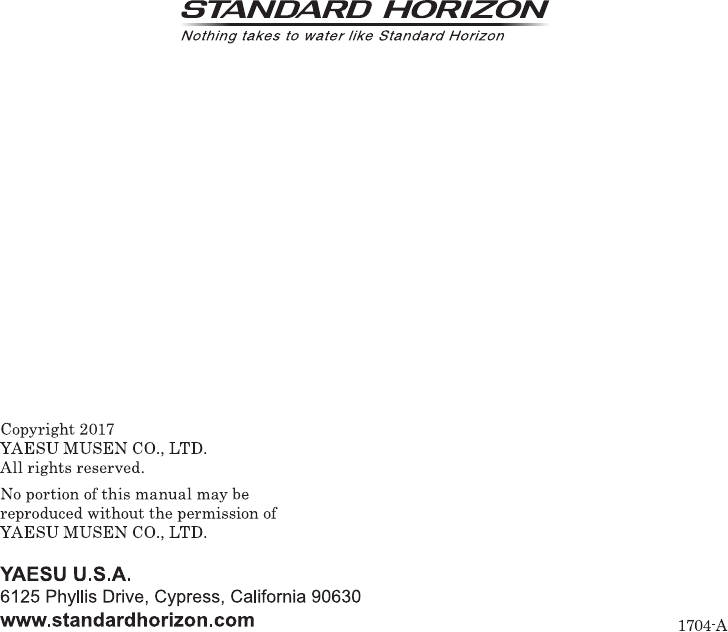
18.9 NMEA 0183 IN/OUT
18.9.1 Data Speed
This menu is used to setup the NMEA 0183 baud rate of the GPS input (Blue
and Green wires) and DSC output (Gray and Brown wires). The default setting
is 4800 bps.
When 38400 bps is selected the AIS sentences (VDM) and DSC sentences
(DSC & DSE) both are output on the Gray and Brown wires after a DSC distress,
position request or AIS transmission is received.
1. [] “SETUP” “GPS SETUP” “NMEA 0183 IN/OUT”
2. Rotate the DIAL/ENT knob to select “DATA SPEED”,
then press the [SELECT] soft key.
3. Rotate the DIAL/ENT knob to select the desired speed
from “4800bps” and “38400bps”.
4. Press the [ENTER] soft key to save the new setting.
5. Press the CLEAR key to return to radio operation.
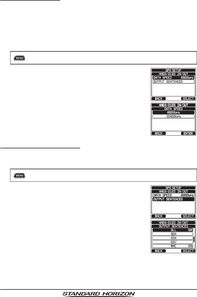
18.9.2 Output Sentences
This selection is used to setup the NMEA output sentences of the GX6000.
By default, all the NMEA sentences are turned “ON”.
1. [] “SETUP” “GPS SETUP” “NMEA 0183 IN/OUT”
2. Rotate the DIAL/ENT knob to select “OUTPUT
SENTENCES”, then press the [SELECT] soft key.
3. Rotate the DIAL/ENT knob to select the desired
sentence type, then press the [SELECT] soft key.
Page 125
GX6000
4. Rotate the DIAL/ENT knob to select “ON” or “OFF”.
5. Press the [ENTER] soft key to save the new setting.
6. Repeat steps 3 through 5 to set the other sentences.
7. Press the CLEAR key to return to radio operation.
NOTE
• Data output will be performed based on the data acquisition order of
priority congured from “ORDER OF PRIORITY”. Refer to section “18.1
ORDER OF PRIORITY” for details.
• While “UNIT POWER” of “OPTION GPS UNIT” is set to OFF, NMEA
sentences will not be output. (OPTION GPS reception data will be
output as is.)
• The output interval of each NMEA sentence depends on the output
timing on the input device. However, sentences which include POS
data will be output at intervals of two seconds or less.
• When all sentences are set to be output, depending on the baud rate,
not all sentences can be output at intervals of one second or less. GSA
and GSV sentences will be output at intervals of around ve seconds.
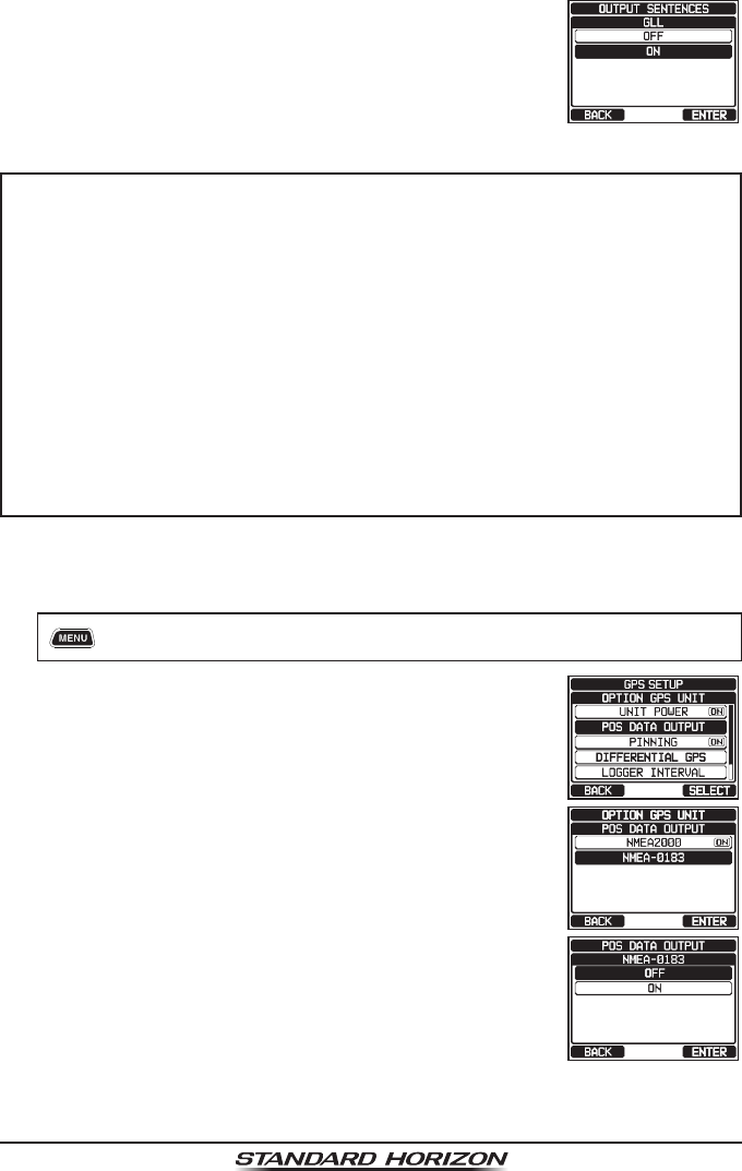
18.10 Position Data Output
Select the connection device to be used when outputting position data.
1. [] “SETUP” “GPS SETUP” “OPTION GPS UNIT”
2. Rotate the DIAL/ENT knob to select “POS DATA
OUTPUT”, then press the [SELECT] soft key.
3. Rotate the DIAL/ENT knob to select “NMEA 2000” or
“NMEA 0183”, then press the [SELECT] soft key.
4. Rotate the DIAL/ENT knob to select “OFF” or “ON”.
5. Press the [ENTER] soft key to store the new setting.
6. Press the CLEAR key to return to radio operation.
Page 126 GX6000
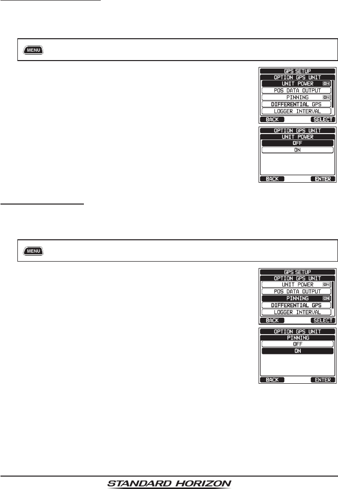
18.11 OPTION GPS UNIT
Change the optional GPS Antenna (SCU-31) setting.
18.11.1 Unit Power
When you use the SCU-31, set this selection to “ON”. The default setting is
“OFF”.
1. [] “SETUP” “GPS SETUP” “OPTION GPS UNIT”
2. Rotate the DIAL/ENT knob to select “UNIT POWER”,
then press the [SELECT] soft key.
3. Rotate the DIAL/ENT knob to select “OFF” or “ON”.
4. Press the [ENTER] soft key to store the new setting.
5. Press the CLEAR key to return to radio operation.
18.11.2 Pinning
This selection is used to enable or disable position updates when the vessel
is not underway. The default setting is “ON”.
1. [] “SETUP” “GPS SETUP” “OPTION GPS UNIT”
2. Rotate the DIAL/ENT knob to select “PINNING”, then
press the [SELECT] soft key.
3. Rotate the DIAL/ENT knob to select “OFF” or “ON”.
ON: When pinning is turned on, the GX6000 will not
update its position unless the ship’s speed over
approximately 0.4 knot.
OFF: When the vessel is underway or stopped, the
GX6000 continuously updates its position. This
improves accuracy of the position x.
4. Press the [ENTER] soft key to save the new setting.
5. Press the CLEAR key to return to radio operation.
Page 127
GX6000
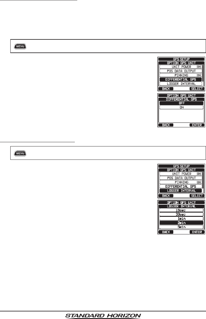
18.11.3 Differential GPS
This selection enables or disables differential GPS function by SBAS (Satellite
Based Augmentation System) such as WAAS, EGNOS and MSAS. In some
areas (Australia for example), the GPS reception can have problems on enabling
the SBAS. The default setting is “OFF”.
1. [] “SETUP” “GPS SETUP” “OPTION GPS UNIT”
2. Rotate the DIAL/ENT knob to select “DIFFERENTIAL
GPS”, then press the [SELECT] soft key.
3. Rotate the DIAL/ENT knob to select “OFF” or “ON”.
4. Press the [ENTER] soft key to store the new setting.
5. Press the CLEAR key to return to radio operation.
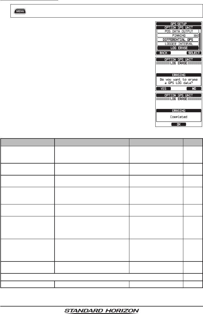
18.11.4 Logger Interval
1. [] “SETUP” “GPS SETUP” “OPTION GPS UNIT”
2. Rotate the DIAL/ENT knob to select “LOGGER
INTERVAL”, then press the [SELECT] soft key.
3. Rotate the DIAL/ENT knob to select the desired time
and press the [ENTER] soft key.
Note: Log time for each logger interval setting
15 sec: Aprox. 25 hours
30 sec: Aprox. 50 hours
1 min: Aprox. 100 hours
2 min: Aprox. 200 hours
5 min: Aprox. 500 hours
4. Press the CLEAR key to return to radio operation.
Page 128 GX6000
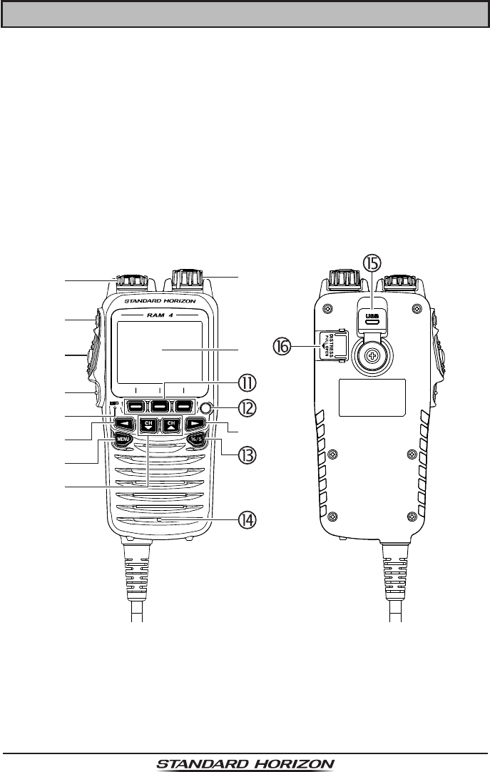
18.11.5 Log Erase
1. [] “SETUP” “GPS SETUP” “OPTION GPS UNIT”
2. Rotate the DIAL/ENT knob to select “LOG ERASE”,
then press the [SELECT] soft key.
3. Press the [YES] soft key. (To cancel, press the [NO]
soft key.)
4. Press the [OK] soft key.
5. Press the CLEAR key to return to radio operation.
18.12 SUMMARY OF THE GPS SETUP
Item Description Default Value Page
ORDER OF PRIORITY Sets the order of priority of the
connection devices when obtaining
position information
NMEA-0183 122
COMPASS DIRECTION Selects the compass direction to
be displayed
COURSE-UP 122
LOCATION FORMAT Selects the coordinate system to
be displayed
ddd°mm.mmmm 122
TIME OFFSET Sets the offset time from the UTC
(available only when “LOCAL” is
selected in the item “TIME AREA”)
00:00 123
TIME AREA Selects the time location to be
displayed, from UTC or local
UTC 123
TIME FORMAT Selects the time format to be
displayed, 12-hour or 24-hour
(fixed to “24H” when “UTC” is
selected in the item “TIME AREA”)
24hour 123
UNITS OF MEASURE Selects the unit if measure when
displaying speed, distance, and
altitude
SPEED: kts (knots)
DISTANCE:
nm (nautical mile)
ALTITUDE: ft (feet)
123
MAGNETIC VARIATION Enables/disables the magnetic
variation function
OFF 123
NMEA 0183 IN/OUT
DATA SPEED Sets the NMEA 0183 data speed 4800bps 124

Page 129
GX6000
Item Description Default Value Page
OUTPUT SENTENCES
Enables/disables NMEA sentences GLL: ON
GGA: ON
GSA: ON
GSV: ON
RMC: ON
DSC/DSE: ON
124
POS DATA OUTPUT Selects the connection device
when outputting position data
NMEA 2000: OFF
NMEA-0183: OFF
125
OPTION GPS UNIT
UNIT POWER Enables/disables the OPTION
GPS UNIT
OFF 126
PINNING Turns on or off GPS position
updates for vessel not underway
OFF 126
DIFFERENTIAL GPS Turns on or off of use of SBAS ON 127
LOGGER INTERVAL Selects the interval time of logging 2 min 127
LOG ERASE Erases the log data −128
Page 130 GX6000
19 SSM-70H (RAM4) REMOTE MIC OPERATION
When a remote microphone is connected to the GX6000, all VHF, DSC, setup
menus, AIS, Navigation, GM (Group Monitor) functions and PA/Fog modes can
be remotely operated. The SSM-70H’s operation is same as GX6000 except
the receiver audio volume setting and squelch level setting. The reason for the
same operation is to make the operation of the radio and SSM-70H mic easy. For
specic operation of the SSM-70H mic review sections in the radio manual. The
SSM-70H is supplied with 23 feet (7 m) of routing cable and can be extended
up to 70 feet (21 m) using three 23 feet (7 m) extension cables model CT-100.
The Intercom feature can be used between the SSM-70H and the GX6000. In
addition, speaker wires are supplied at the panel mount of the routing cable for
external speakers to be connected in noisy environments.
19.1 REMOTE MIC CONTROLS
Power/VOL knob
Press and hold this knob to turn the transceiver and the remote mic on or off.
Rotate this knob to adjust the internal speaker volume.

Page 131
GX6000
DIAL/ENT knob
While the normal screen is displayed, rotate the DIAL/ENT knob to select
your desired channel. While the MENU screen is displayed, rotate the knob
to select your desired menu item.
Secondary uSe
Press this knob to enter a selection in the MENU.
SQL key (Squelch control)
Press this key to activate the squelch adjusting mode. Press the CH▲ or
CH▼ key to adjust the squelch threshold level.
PTT (Push-To-Talk) switch
Push this switch to enable the transmitter.
CLEAR/ key
Press this key to cancel a menu selection. Press and hold this key to acti-
vate the key lock function. Press and hold this key again to deactivate the
key lock function.
Microphone
The internal microphone transmits your voice reducing background noise
using Clear Voice Noise Reduction Technology.
Note: Position your mouth about 1/2” (1.5 cm) away from the microphone
hole and speak in a normal voice.
◄/► key
Press these keys to switch the function of soft keys
Secondary uSe
While the MENU screen is displayed, press the key to slide the on-screen
menu to the right/left side.
MENU key
Press this key to access the MENU.
CH▼/CH▲ key
These keys are used to change the operating channel.
Press the key momentarily, the channel increases/decreases one step.
Holding the key, the channel increases/decreases continuously.
Secondary uSe
While the MENU screen is displayed, press the key to slide the on-screen
menu upward/downward.
When in the PA or Fog mode, press the key to change the channel.
Display
Full dot matrix display, 222 by 162 pixels.
Soft keys
These three programmable keys can be customized through the setup
menu mode. When pressing one of these keys briey, the key functions
will appear at the bottom of the display. Refer to section “19.2 RAM4 SOFT
KEY ASSIGNMENT” for details.
Strobe Light
When the [STROBE] soft key is pressed, the internationally-recognized
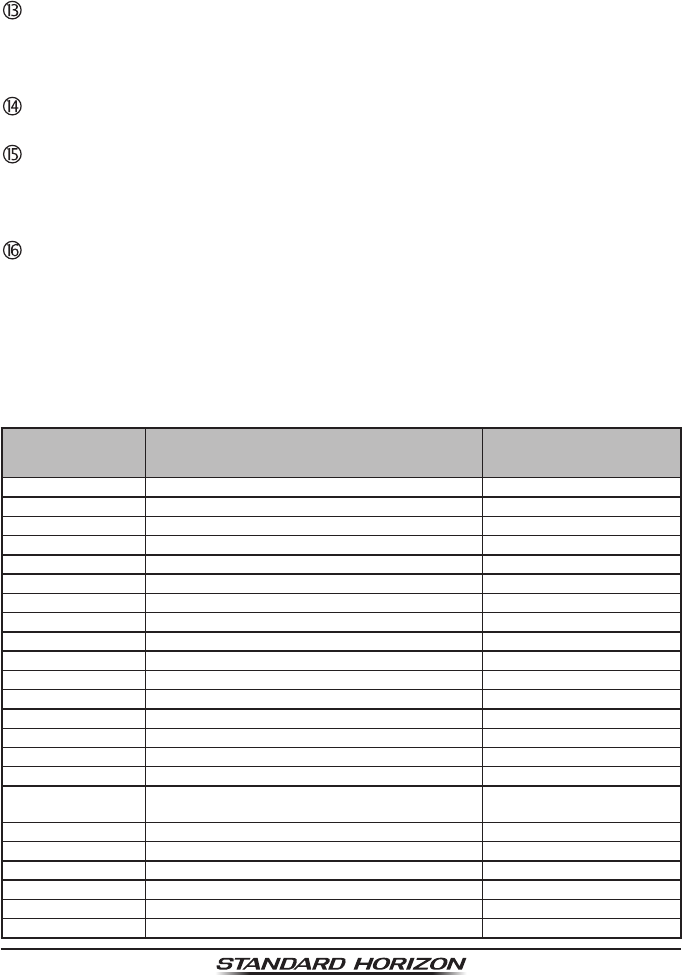
Page 132 GX6000
Morse Code “S.O.S” message will light and ash repeatedly.
From MENU → SETUP → CONFIGURATION → STROBE LED, you can
select one option from “CONTINUOUS”, “SOS”, “BLINK 1”, “BLINK 2” and
“BLINK 3”.
16/S key
Pressing this key immediately recalls channel 16 from any channel location.
Holding down this key recalls the SUB channel (The default setting is channel
9). Pressing this key again reverts to the previous selected working channel.
Speaker
The internal speaker is located here.
DATA jack
Use the micro USB type B jack for SSM-70H (RAM4) rmware updates.
Note: When the DATA jack is securely covered with rubber cap, the SSM-
70H meets the waterproong performance.
DISTRESS key
This key is used to send a DSC distress call. Refer to section “10 DIGITAL
SELECTIVE CALLING (DSC)”.
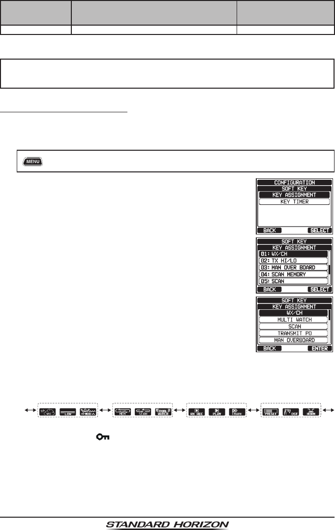
19.2 RAM4 SOFT KEY ASSIGNMENT
From this menu, you can assign desired functions to each RAM4 soft key from numbers
01 to 12. You can also set how long the soft key icon will be displayed after the corre-
sponding soft key is pressed. The keys maybe setup to control the following functions:
DISPLAY FUNCTION
SOFT KEY NUMBERS
ASSIGNED AS DEFAULT
(See the next page.)
NONE − −
TX HI/LO Selects transmit power. 02
WX/CH Switches channels between weather and marine. 01
SCAN Turns on or off scanning function. 05
DUAL WATCH Starts and stops dual watch scan. 06
MARK POSITION Marks the current position for a “Waypoint”. 09
SCAN MEMORY Add or remove channels from memory channel scan. 04
PRESET Programs or deletes the preset memory channel. 10
MAN OVER BOARD Marks the position where a person falls overboard. 03
NOISE CANCEL Enables the noise canceling settings display.
CH NAME Edit channel names.
STROBE Turns on or off the strobe light LED.
SCRAMBLER Congures the secret communication settings.
COMPASS Enables the “Compass” display.
WAYPOINT Enables the “Waypoint” or “Route” navigation display.
FOG HORN Select FOG HORN mode.
INTERCOM Activates intercom between radio and RAM4 mic
(optional RAM4 required).
GPS LOGGER Starts and stops logging position data.
AIS DISPLAY Shows the “AIS” display.
HORN BUTTON Activates the Fog Horn function. 12
PUBLIC ADDRESS Activates the PA function.
RX RECORD Records received voices. 07
RX SENSE Toggles between LOCAL and DISTANCE. 11
Page 133
GX6000
DISPLAY FUNCTION
SOFT KEY NUMBERS
ASSIGNED AS DEFAULT
(See the next page.)
PLAY Plays recorded voices. 08
NOTE
You can assign functions to soft keys on each of the transceiver and
the optional SSM-70H (RAM4) remote mic.
19.2.1 Key Assignment
Congure all settings on the SSM-70H (RAM4) remote mic for which you want
to assign functions to soft keys.
1. [] “SETUP” “CONFIGURATION” “SOFT KEY”
2. Rotate the DIAL/ENT knob to select “KEY ASSIGN-
MENT”, then press the [SELECT] soft key.
3. Rotate the DIAL/ENT knob to select the key number
to be programmed, and press the [SELECT] soft key.
4. Rotate the DIAL/ENT knob to select a new function to
be assigned, and press the [ENTER] soft key. Avail-
able functions are listed below. By selecting “NONE”
the soft key assignment is removed.
5. Repeat steps 3 and 4 to program other soft keys. Up
to 24 functions can be assigned.
The VHF radio's functions can be assigned to the maximum of 12 soft keys.
Pressing the ►/◄ key each time shows three different soft keys.
01 04 10
02 05 11
03 06 12
07 08 09
(The illustration above is the default setting.)
6. Press the CLEAR/ key to return to radio operation.
Page 134 GX6000
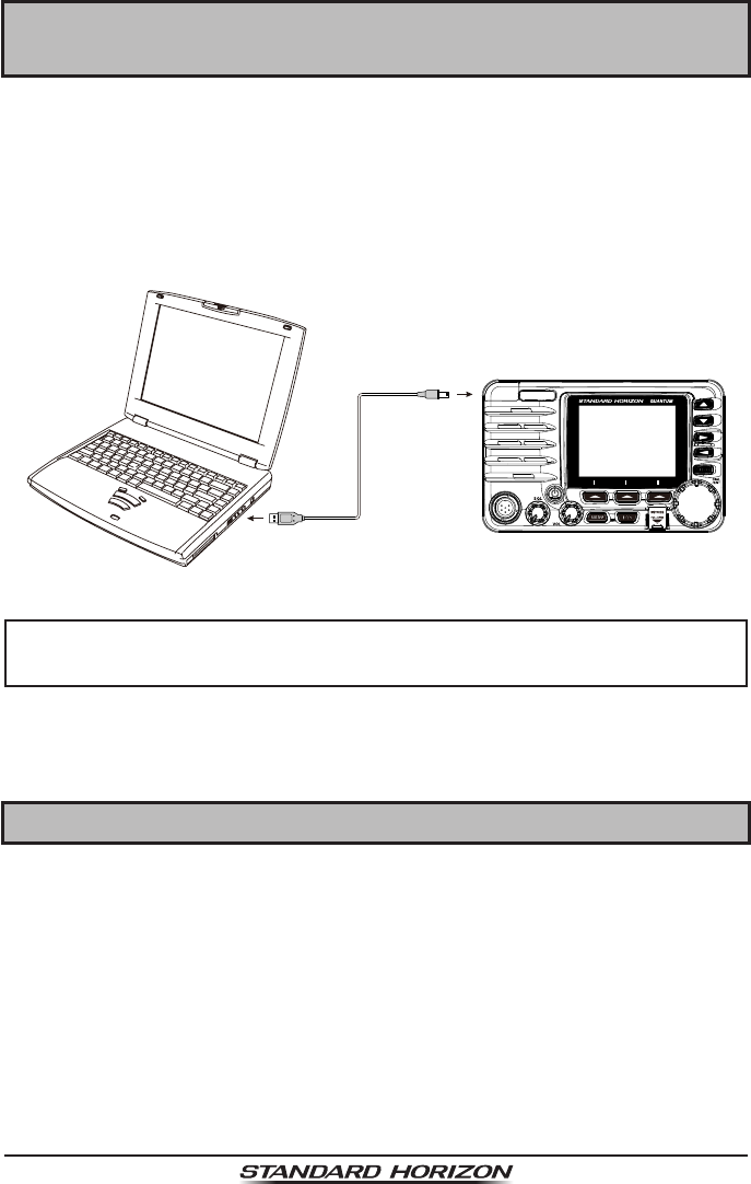
20 CONNECTING A USB DATA TERMINAL TO
THE PC
The GX6000 settings can be programmed using the USB terminal and PC
Programming Software. You can also download the log data from the radio
by using the PC Programming Software which may be downloaded from the
Standard Horizon website. The PC Programming Software is compatible with
Windows®.
To connect a PC, use the supplied USB cable through the DATA jack of the
GX6000.
DATA jack
supplied USB cable
CAUTION
The DATA jack is NOT designed to be waterproof when the cover is
opened. Connect the radio and PC in a dry location.
If you have further questions, please feel free to contact Product Support at:
Phone: (800) 767-2450
Email: marinetech@yaesu.com
21 MAINTENANCE
The inherent quality of the solid-state components used in this transceiver will
provide many years of continuous use. Taking the following precautions will
prevent damage to the transceiver.
• Never key the microphone unless an antenna or suitable dummy load is
connected to the transceiver.
• Ensure that the supply voltage to the transceiver does not exceed 16 VDC
or fall below 11 VDC.
• Use only STANDARD HORIZON approved accessories and replacement parts.
In the unlikely event of serious problems, please contact your Dealer or our
repair facility. Address and phone numbers for this facility, as well as warranty
information, are contained in section “23 WARRANTY”.

Page 135
GX6000
21.1 REPLACEMENT PARTS
Occasionally an owner needs a replacement mounting bracket or knob.
These can be ordered from our Parts Department by emailing
yaesuparts@yaesu.com or calling:
Marine Division of YAESU U.S.A.
6125 Phyllis Drive, Cypress, California 90630
Telephone (714) 827-7600
Commonly requested parts, and their part numbers are listed below.
• Power Cord: T9027407
• VOL and SQL Knob: RA6057800
• DIAL/ENT Knob: RA6057700
• Mounting Bracket: RA6060600
• Mounting Bracket Knob: RA0978600
• Microphone Hanger: RA0458800
• RAM4 Mic Routing Cable Assembly: S8101512
• USB Cable: T9101648
21.2 FACTORY SERVICE
In the unlikely event that the radio fails to perform or needs servicing, please
contact the following:
Standard Horizon
Attention Marine Repair Department
6125 Phyllis Drive, Cypress, California 90630, U.S.A.
Telephone (800) 366-4566
For repairs in Canada
Westcom Marine
488 East 62nd Avenue Vancouver BC V5X2G1
Telephone (604) 327-6280
An “RA” (Return Authorization) number is not necessary to send a product in
for service. Include a brief note describing the problem along with your name,
return address, phone number, and proof of purchase.

Page 136 GX6000
21.3 TROUBLESHOOTING CHART
SYMPTOM PROBABLE CAUSE REMEDY
Transceiver fails to
power up.
No DC voltage to the
transceiver, or blown fuse.
a. Check the 12VDC battery connections
and the fuse.
b. The key needs to be pressed and held
to turn the radio on.
Transceiver
blows fuse when
connected to
power supply.
Reversed power wires. Check the power cable for DC
voltage, or replace the fuse (7A).
Make sure the red wire is connected to the
positive (+) battery post, and the black wire
is connected to the negative (–) battery post.
If the fuse still blows, contact your Dealer.
Popping or whin-
ing noise from
the speaker while
engine runs.
Engine noise. Re-route the DC power cables away from
the engine. Add noise suppressor on power
cable. Change to resistive spark plug wires
and/or add an alternator whine lter.
Sound is not emit-
ted from the inter-
nal or external
speaker.
Accessory cable. Check the connections of the acces-
sory cable. External speaker cable (WHITE/
SHIELD) shorted together.
Sound is not emit-
ted from the PA
speaker.
Accessory cable. Check the connections of the accessory
cable. PA speaker cable (RED/SHIELD)
shorted together.
Receiving station
reports low trans-
mit power, even
with transceiver
set to HI power.
Antenna. Have the antenna checked or test the trans-
ceiver with another antenna. If the problem
persists, contact your Dealer for servicing.
“HI BATTERY” or
“LO BATTERY”
message appears
when the power is
turned on.
The power supply voltage
is too high or too low.
Conrm that the connected power supply
voltage is between 11 volts and 16.5 volts
DC.
Your position is not
displayed.
SCU-31 cable. Check the SCU-31 cable connection.
Accessory cable. Check the accessory cable connection.
Some GPS use the battery ground for NMEA
connection.
Setting of the GPS chart
plotter.
Check the output signal format of the GPS
navigation receiver. This radio requires
NMEA 0183 and NMEA 2000 format with
GLL, RMB, or RMC sentence as an output
signal. If the GPS has a baud rate setting
make sure to select 4800 and parity to
NONE.

Page 137
GX6000
22 CHANNEL ASSIGNMENTS
Tables on the following columns list the VHF Marine Channel assignments for
U.S.A. and International use. Below are listed some data about the charts.
1. VTS. Where indicated, these channels are part of the U.S. Coast Guard’s
Vessel Trafc System.
2. Alpha channel numbers, that is, channel numbers followed by the letter A
(such as Channel 07A) are simplex channels on the U.S.A. or Canadian
channel assignments whose counterparts in the International assignments
are duplex channels. International channels do not use “alpha” numbers. If
you call the Coast Guard on Channel 16, they will sometimes ask you to “go
to channel 22 Alpha”. This is a channel assigned to U.S.A, and Canadian
Coast Guards for handling distress and other calls. If your radio is set for
International operation you will go to Channel 22 instead of 22A, and will
not be able to communicate with the Coast Guard. To use Channel 22A,
your radio must be set for USA or Canada operation, usually by a U/I/C
(USA/International/Canada) control or combination of controls. Channel
22 (without an “A”) is an International duplex channel for port operations.
Some radios indicate an “A” adjacent to the alpha channels on the display;
on others “alpha” is not indicated but the proper channel is selected based
on the U/I/C setting.
3. Bridge-to-Bridge channels (for example, Channel 13) are for use by bridge
operators on inter-coastal waterways and rivers. It is also used by marine
vessels in the vicinity of these bridges for navigation and for communicating
with the bridge operators. Note that a limit of 1 Watt is specied for these
channels.
4. The S/D column on the chart indicates either S (simplex) or D (duplex).
Simplex means transmitting and receiving on the same frequency. Only
one party at a time can talk, unlike a telephone. Be sure to say “over” and
release your microphone push-to-talk switch at the end of each transmis-
sion. Duplex operation involves the use of one frequency for transmitting
and a separate frequency for receiving. On channels specied as duplex on
the charts, correct mode of operation is established automatically by your
radio when you select a channel; you cannot change the mode. And you
still must release the push-to-talk switch after each transmission in order
to listen to the radio.
5. Channels normally used by recreational boaters are those that include the
term “non-commercial” in the Channel Use column of the chart. Some
of these are shared with other users and some are used only in certain
geographic regions.

Page 138 GX6000
6. Marine vessels equipped with VHF radios are required to monitor Channel
16.
7. 156.050 MHz and 156.175 MHz are available for port operations and
commercial communications purposes when used only within the U.S. Coast
Guard designated Vessel Trafc Services (VTS) area of New Orleans, on
the lower Mississippi River from the various pass entrances in the Gulf of
Mexico to Devil’s Swamp Light at River Mile 242.4 above head of passes
near Baton Rouge.
8. 156.250 MHz is available for port operations communications use only
within the U.S. Coast Guard designated VTS radio protection areas of New
Orleans and Houston described in Sec. 80.383. 156.250 MHz is available
for intership port operations communications used only within the area of
Los Angeles and Long Beach harbors, within a 25- nautical mile radius of
Point Fermin, California.
9. 156.550 MHz, 156.600 MHz and 156.700 MHz are available in the U.S.
Coast Guard designated port areas only for VTS communications and
in the Great Lakes available primarily for communications relating to the
movement of ships in sectors designated by the St. Lawrence Seaway
Development Corporation or the U.S. Coast Guard. The use of these
frequencies outside VTS and ship movement sector protected areas is
permitted provided they cause no interference to VTS and ship movement
communications in their respective designated sectors.
10. Use of 156.875 MHz is limited to communications with pilots regarding the
movement and docking of ships. Normal output power must not exceed 1
watt. 5: 156.375 MHz and 156.650 MHz are available primarily for intership
navigational communications. These frequencies are available between
coast and ship on a secondary basis when used on or in the vicinity of locks
or drawbridges. Normal output power must not exceed 1 watt. Maximum
output power must not exceed 10 watts for coast stations or 25 watts for
ship stations.
11. On the Great Lakes, in addition to bridge-to-bridge communications, 156.650
MHz is available for vessel control purposes in established vessel trafc
systems. 156.650 MHz is not available for use in the Mississippi River
from South Pass Lighted Whistle Buoy “2” and Southwest Pass entrance
Mid-channel Lighted Whistle Buoy to mile 242.4 above Head of Passes
near Baton Rouge. Additionally, it is not available for use in the Mississippi
River-Gulf Outlet, the Mississippi River-Gulf Outlet Canal, and the Inner
Harbor Navigational Canal, except to aid the transition from these areas.
12. Use of 156.375 MHz is available for navigational communications only in
the Mississippi River from South Pass Lighted Whistle Buoy “2” and South-

Page 139
GX6000
west Pass entrance Mid channel Lighted Whistle Buoy to mile 242.4 above
head of Passes near Baton Rouge, and in addition over the full length of
the Mississippi River-Gulf Outlet Canal from entrance to its junction with the
Inner Harbor Navigation Canal, and over the full length of the Inner Harbor
Navigation Canal from its junction with the Mississippi River to its entry to
Lake Pontchartrain at the New Seabrook vehicular bridge.
13. Within 120 km (75 miles) of the United States/Canada border, in the area of
the Puget Sound and the Strait of Juan de Fuca and its approaches, 157.425
MHz is half of the duplex pair designated as Channel 88. In this area, Chan-
nel 88 is available to ship stations for communications with public coast
stations only. More than 120 km (75 miles) from the United States/Canada
border in the area of the Puget Sound and the Strait of Juan de Fuca, its
approaches, the Great Lakes, and the St. Lawrence Seaway, 157.425
MHz is available for intership and commercial communications. Outside
Puget Sound area and its approaches and the Great Lakes, 157.425 MHz
is also available for communications between commercial shing vessels
and associated aircraft while engaged in commercial shing activities.
14. When the frequency 156.850 MHz is authorized, it may be used addition-
ally for search and rescue training exercises conducted by state or local
governments.
15. The frequency 156.850 MHz is additionally available to coast stations on
the Great Lakes for transmission of scheduled Coded Marine Weather Fore-
casts (MAFOR), Great Lakes Weather Broadcast (LAWEB) and scheduled
Notices to Mariners or Bulletins. F3C and J3C emissions are permitted.
Coast Stations on the Great Lakes must cease weather broadcasts which
cause interference to stations operating on 156.800 MHz until the interfer-
ence problem is resolved.
16. The frequency 157.100 MHz is authorized for search and rescue training
exercises by state or local government in conjunction with U.S. Coast Guard
stations. Prior U.S. Coast Guard approval is required. Use must cease
immediately on U.S. Coast Guard request.
17. The duplex pair for channel 20 (157.000/161.600 MHz) may be used for
ship to coast station communications.
18. Available for assignment to coast stations, the use of which is in accord
with an agreed program, for the broadcast of information to ship stations
concerning the environment.
Page 140 GX6000
VHF MARINE CHANNEL CHART
CH U C I S/D TX RX CHANNEL USE
01 X X D 156.050 160.650 Public Correspondence (Marine Operator)
01A X S 156.050 Port Operation and Commercial.
VTS in selected areas
02 X X D 156.100 160.700 Public Correspondence (Marine Operator)
03 X X D 156.150 160.750 Public Correspondence (Marine Operator)
03A X S 156.150 U.S. Government Only, Coast Guard
04 X D 156.200 160.800 Public Correspondence (Marine Operator),
Port operation, ship movement
04A X S 156.200 Pacic coast: Coast Guard, East Coast:
Commercial shing
05 X D 156.250 160.850 Public Correspondence (Marine Operator),
Port operation, ship movement
05A X X S 156.250 Port operation. VTS in Seattle
06 X X X S 156.300 Inter-ship Safety
07 X D 156.350 160.950 Public Correspondence (Marine Operator),
Port operation, ship movement
07A X X S 156.350 Commercial
08 X X X S 156.400 Commercial (Inter-ship only)
09 X X X S 156.450 Boater Calling channel, Commercial &
Non-commercial (Recreational)
10 X X X S 156.500 Commercial
11 X X X S 156.550 Commercial. VTS in selected areas.
12 X X X S 156.600 Port operation. VTS in selected areas.
13 X X X S 156.650 Inter-ship Navigation Safety (Bridge-to-
bridge)
14 X X X S 156.700 Port operation. VTS in selected areas.
15 X S - - - 156.750 Environmental (Receive only)
15 X X S 156.750 Commercial, non-commercial, ship
movement (1 W)
16 X X X S 156.800 International Distress, Safety and Calling
17 X X X S 156.850 State Controlled (1 W)
18 X D 156.900 161.500 Port operation, ship movement
18A X X S 156.900 Commercial
19 X D 156.950 161.550 Port operation, ship movement
1019 X S 156.950
2019 X S 161.550
19A X S 156.950 US: Commercial
19A X S 156.950 Coast Guard
20 X X X D 157.000 161.600 Canadian Coast Guard Only,
International: port operations and shipment
1020 X S 157.000
2020 X S 161.600
20A X S 157.000 Port operation
21 X D 157.050 161.650 Port operation, ship movement
21A X X S 157.050 U.S. Government Only, Canadian Coast
Guard
21B X - - - 161.650 CMB Service
22 X D 157.100 161.700 Port operation, ship movement
22A X X S 157.100
US and Canadian Coast Guard Liaison
and Maritime Safety Information
Broadcasts announced on channel 16
23 X X D 157.150 161.750 Public Correspondence (Marine Operator)
23A X S 157.150 U.S. Government Only

Page 141
GX6000
VHF MARINE CHANNEL CHART
CH U C I S/D TX RX CHANNEL USE
23B X - - - 161.750 CMB Service
24 X X X D 157.200 161.800 Public Correspondence (Marine Operator)
25 X X X D 157.250 161.850 Public Correspondence (Marine Operator)
25B X - - - 161.850 CMB Service
26 X X X D 157.300 161.900 Public Correspondence (Marine Operator)
27 X X X D 157.350 161.950 Public Correspondence (Marine Operator)
28 X X X D 157.400 162.000 Public Correspondence (Marine Operator)
28B X - - - 162.000 CMB Service
60 X X D 156.025 160.625 Public Correspondence (Marine Operator)
61 X D 156.075 160.675 Public Correspondence (Marine Operator),
Port operation, ship movement
61A X X S 156.075 Public Coast: Coast Guard;
East Coast: commercial shing only
62 X D 156.125 160.725 Public Correspondence (Marine Operator),
Port operation, ship movement
62A X S 156.125 Public Coast: Coast Guard;
East Coast: commercial shing only
63 X D 156.175 160.775 Public Correspondence (Marine Operator),
Port operation, ship movement
63A X X S 156.175 Port Operation and Commercial.
VTS in selected areas.
64 X X D 156.225 160.825 Public Correspondence (Marine Operator),
Port operation, ship movement
64A X X S 156.225
Public Correspondence (Marine
Operator),
Port operation, ship movement
65 X D 156.275 160.875 Public Correspondence (Marine Operator),
Port operation, ship movement
65A X X S 156.275 Port Operations
66 X D 156.325 160.925 Public Correspondence (Marine Operator),
Port operation, ship movement
66A X X S 156.325 Port Operations
67 X X X S 156.375
US: Commercial. Used for Bridge-
to-bridge communications in lower
Mississippi River. Inter-ship only.
Canada: Commercial shing, S&R
68 X X X S 156.425 Non-commercial (Recreational)
69 X X X S 156.475
US: Non-commercial (Recreational),
Canada: Commercial shing only,
International: Inter-ship, Port operations
and Ship movement
70 X X X S - - - 156.525 Digital selective calling (voice
communications not allowed)
71 X X X S 156.575
US, Canada: Non-commercial
(Recreational),
International: Port operations and Ship
movement
72 X X X S 156.625 Non-commercial (Inter-ship only)
73 X X X S 156.675
US: Port Operations,
Canada: Commercial shing only,
International: Inter-ship, Port operations
and Ship movement
Page 142 GX6000
VHF MARINE CHANNEL CHART
CH U C I S/D TX RX CHANNEL USE
74 X X X S 156.725
US: Port Operations,
Canada: Commercial shing only,
International: Inter-ship, Port operations
and Ship movement
75 X X X S 156.775 Port Operations (Inter-ship only) (1W)
76 X X X S 156.825 Port Operations (Inter-ship only) (1W)
77 X X S 156.875 Port Operations (Inter-ship only) (1W)
77 X S 156.875 Port Operations (Inter-ship only)
78 X D 156.925 161.525 Public Correspondence (Marine Operator),
Port operation, ship-movement
1078 X S 156.925
2078 X S 161.525
78A X X S 156.925 Non-commercial (Recreational)
79 X D 156.975 161.575 Port operation and Ship movement
1079 X S 156.975
2079 X S 161.575
79A X X S 156.975 Commercial
80 X D 157.025 161.625 Port operation, ship movement
80A X X S 157.025 Commercial
81 X D 157.075 161.675 Port operation, ship movement
81A X S 157.075 U.S. Government Only -
Environmental protection operations.
81A X S 157.075 Canadian Coast Guard Only
82 X D 157.125 161.725 Public Correspondence (Marine Operator),
Port operation, ship movement
82A X X S 157.125 U.S. Government Only,
Canadian Coast Guard Only
83 X D 157.175 161.775 Public Correspondence (Marine Operator)
83A X X S 157.175 U.S. Government Only,
Canadian Coast Guard Only
83B X - - - 161.775 CMB Service
84 X X X D 157.225 161.825 Public Correspondence (Marine Operator)
85 X X X D 157.275 161.875 Public Correspondence (Marine Operator)
86 X X X D 157.325 161.925 Public Correspondence (Marine Operator)
87 X X S 157.375 Port operation, ship movement
87A X S 157.375 Public Correspondence (Marine Operator)
88 X X S 157.425 Port operation, ship movement
88A X S 157.425 Commercial, Inter-ship Only
WX01 X X X D - - - 162.550 Weather (receive only)
WX02 X X X D - - - 162.400 Weather (receive only)
WX03 X X X D - - - 162.475 Weather (receive only)
WX04 X X X D - - - 162.425 Weather (receive only)
WX05 X X X D - - - 162.450 Weather (receive only)
WX06 X X X D - - - 162.500 Weather (receive only)
WX07 X X X D - - - 162.525 Weather (receive only)
WX08 X X X D - - - 161.650 Weather (receive only)
WX09 X X X D - - - 161.775 Weather (receive only)
WX10 X X X D - - - 163.275 Weather (receive only)
NOTE: Simplex channels, 03A, 21A, 23A, 61A, 64A, 81A, 82A and 83A CANNOT be lawfully
used by the general public in U.S.A. waters.

Page 143
GX6000
23 WARRANTY
Marine Products Limited Warranty
PLEASE NOTE
The following “Limited Warranty” is for valid for products that have been
purchased in the United States and Canada. For limited Warranty details
outside the United States, contact the dealer in your country.
STANDARD HORIZON (a division of YAESU U.S.A.) warrants, to the original
purchaser only, each new Marine Communications Product (“Product”) manu-
factured and/or supplied by STANDARD HORIZON against defects in materials
and workmanship under normal use and service for a period of time from the
date of purchase as follows:
Fixed Mount and Portable Transceivers
1 year - if purchased before 01/01/91
3 years - if purchased between 01/01/91 and 01/01/94
3 years Waterproof - if purchased after 01/01/94
Loud hailers
1 year - if purchased before 01/01/91
3 years - if purchased after 01/01/91
Associated Chargers
1 year - if purchased before 01/01/91
3 years - if purchased after 01/01/91
Associated Batteries - 1 year. Note: Batteries will be deemed deective only
if storage capacity drops below 80% of rated capacity or if leakage develops.
Associated Accessories - 1 year. Includes: Microphones/Handsets, External
Speakers, Antennas, Carrying Accessories, Power Supplies, and Signaling
Boards.
To receive warranty service, the purchaser must deliver the Product, transporta-
tion and insurance prepaid, to STANDARD HORIZON, Attention Marine repairs
6125 Phyllis Drive, Cypress, California 90630, U.S.A. Include proof of purchase
indicating model. serial number, and date of purchase. STANDARD HORIZON
will return the Product to the purchaser freight prepaid. Products purchased
prior to January 1, 1991 will bear the STANDARD HORIZON warranty terms
in effect prior to that date.
In the event of a defect, malfunction or failure of the Product during the warranty
period, STANDARD HORIZON’s liability for any breach of contract or any
breach of express or implied warranties in connection with the sale of Products
shall be limited solely to repair or replacement, at its option, of the Product or

Page 144 GX6000
part(s) therein which, upon examination by STANDARD HORIZON, appear to
be defective or not up to factory specications. STANDARD HORIZON may, at
its option, repair or replace parts or subassemblies with new or reconditioned
parts and subassemblies. Parts thus repaired or replaced are warranted for
the balance of the original applicable warranty.
STANDARD HORIZON will not warrant installation, maintenance or service of
the Products. In all instances, STANDARD HORIZON’s liability for damages
shall not exceed the purchase price of the defective Product.
This warranty only extends to Products sold within the 50 States of the United
States of America and the District of Columbia.
STANDARD HORIZON will pay all labor to repair the product and replace-
ment parts charges incurred in providing the warranty service except where
purchaser abuse or other qualifying exceptions exist. The purchaser must pay
any transportation expenses incurred in returning the Product to STANDARD
HORIZON for service.
This limited warranty does not extend to any Product which has been subjected
to misuse, neglect, accident, incorrect wiring by anyone other than STANDARD
HORIZON, improper installation, or subjected to use in violation of instructions
furnished by STANDARD HORIZON, nor does this warranty extend to Products
on which the serial number has been removed, defaced, or changed. STAN-
DARD HORIZON cannot be responsible in any way for ancillary equipment not
furnished by STANDARD HORIZON which is attached to or used in connection
with STANDARD HORIZON’s Products, or for the operation of the Product with
any ancillary equipment, and all such equipment is expressly excluded from
this warranty. STANDARD HORIZON disclaims liability for range, coverage, or
operation of the Product and ancillary equipment as a whole under this warranty.
STANDARD HORIZON reserves the right to make changes or improvements
in Products, during subsequent production, without incurring the obligation to
install such changes or improvements on previously manufactured Products.
The implied warranties which the law imposes on the sale of this Product are
expressly LIMITED, in duration, to the time period specied above. STANDARD
HORIZON shall not be liable under any circumstances for consequential damag-
es resulting from the use and operation of this Product, or from the breach of this
LIMITED WARRANTY, any implied warranties, or any contract with STANDARD
HORIZON. IN CONNECTION WITH THE SALE OF ITS PRODUCTS, STAN-
DARD HORIZON MAKES NO WARRANTIES, EXPRESS OR IMPLIED AS TO
THE MERCHANTABILITY OR FITNESS FOR A PARTICULAR PURPOSE OR
OTHERWISE, EXCEPT AS EXPRESSLY SET FORTH HEREIN.

Page 145
GX6000
Some states do not allow the exclusion or limitation of incidental or consequen-
tial damages, or limitation on how long an implied warranty lasts, so the above
limitations or exclusions may not apply. This warranty gives specic legal rights,
and there may be other rights which may vary from state to state.
ONLY PRODUCTS SOLD ON OR AFTER JANUARY 1, 1991 ARE COVERED
UNDER THE TERMS OF THIS LIMITED WARRANTY.
ON-LINE WARRANTY REGISTRATION
THANK YOU for buying STANDARD HORIZON (a division of YAESU
U.S.A.) products! We are condent your new radio will serve your
needs for many years!
Please visit www.standardhorizon.com to register your Marine
VHF. It should be noted that visiting the website from time to time may
be benecial to you, as new products are released they will appear
on the STANDARD HORIZON website. Also a statement regarding
product support should be added to the manual.
Product Support Inquiries
If you have any questions or comments regarding the use of the radio,
you can visit the STANDARD HORIZON website to send an E-Mail
or contact the Product Support team at (714) 827-7600 ext 6300 M-F
8:00-5:00 PST.
In addition to the warranty, STANDARD HORIZON includes a lifetime
“at rate” and “customer loyalty” programs to provide service after the
warranty period has expired. If you wish to obtain the at rate price
for out-of-warranty repair, you must include the information on the
Owner’s Record with the unit when you return it to your Dealer or to
STANDARD HORIZON.
Lifetime Flat Rate Service Program: For the original Owner only, for
the lifetime of the unit, STANDARD HORIZON will repair the unit to
original specications.
Note: The at rate amount is payable by the Owner only if STANDARD
HORIZON or the STANDARD HORIZON Dealer determines that a
repair is needed. After the repair, a 90-day warranty will be in effect
from the date of return of the unit to the Owner.
This service program is not available for equipment which has failed as
a result of neglect, accident, breakage, misuse, improper installation
or modication, or water damage (depending on the product).

Page 146 GX6000
24 SPECIFICATIONS
Performance specications are nominal, unless otherwise indicated, and are
subject to change without notice. Measured in accordance with TIA/EIA-603.
24.1 GENERAL
Channels ..............................................................All USA, International and Canadian
Normal Input Voltage ..................................................................................... 13.8 V DC
Operating Voltage Range ........................................................................ 11 V to 16.5 V
Current Drain
Standby ...........................................................................................................0.55 A
Receiver (at Maximum AF Output) ...................................................................0.9 A
Transmit ................................................................................... 5.0 A (Hi), 1.0 A (Lo)
DSC Transmitted Call Log ..........................................................................................24
DSC Distress Call Log ................................................................................................27
DSC Received Call Log ..............................................................................................64
Individual Call Directory ..............................................................................................80
Group Call Directory ...................................................................................................32
Waypoint Directory ...................................................................................................100
Display Type ............................................................................... 2.8” x 2” (70 x 51 mm)
Full Dot Matrix (222 x 162 pixels)
Dimensions (WxHxD) ................................ 6.9” x 4.3” x 6.8” (175.5 x 110 x 173.3 mm)
Flush-Mount Dimensions (WxHxD) ............ 6.2” x 3.7” x 6.2” (157.4 x 93.4 x 158 mm)
Weight ................................................................................................. 3.7 lbs (1.66 kg)
24.2 TRANSMITTER
Frequency Range ................................................ 156.025 MHz to 157.425 MHz (USA)
156.025 MHz to 161.600 MHz (INTERNATIONAL)
RF Output Power .............................................................................25 W (Hi), 1 W (Lo)
Conducted Spurious Emissions.......................... Less than −80 dBc (Hi), −66 dBc (Lo)
Audio Response .........................................................within +1/−3dB of a 6 dB/Octave
pre-emphasis characteristic at 300 to 3000 Hz
Audio Distortion .......................................................................................Less than 5 %
Modulation ...................................................16K0G3E (for Voice), 16K0G2B (for DSC)
Frequency Stability .........................................................±0.0003 % (−20 °C to +60 °C)
FM Hum and Noise............................................................................................... 50 dB
24.3 RECEIVER (for Voice and DSC)
Frequency Range ...........................................................156.050 MHz to 163.275 MHz
Sensitivity
20 dB Quieting ............................................................................................. 0.35 µV
12 dB SINAD ............................................................................................... 0.30 µV
Squelch Sensitivity (Threshold) ................................................................... 0.13 µV
Modulation Acceptance Bandwidth.................................................................. ±7.5 kHz
Selectivity (Typical)
Spurious and Image Rejection ...............................80 dB for Voice (75 dB for DSC)
Intermodulation and Rejection ...............................80 dB for Voice (75 dB for DSC)
Audio Output................................................ 10 W (at 8 ohms external speaker output)
Audio Response ......................................................... within +1/–3dB of a 6 dB/Octave
de-emphasis characteristic at 300 to 3000 Hz

Page 147
GX6000
Frequency Stability .........................................................±0.0003 % (–20 °C to +60 °C)
Channel Spacing ................................................................................................ 25 kHz
DSC Format ..........................................................................................ITU-R M.493-13
Attenuator (Local) ....................................................................................Approx. 10 dB
24.4 RECEIVER (for AIS)
Frequency..................................................161.975 MHz (CH A), 162.025 MHz (CH B)
Sensitivity ............................................................................... 0.5 µV (at 12 dB SINAD)
Selectivity(Typical)
Spurious and Image Rejection ........................................................................ 70 dB
Intermodulation and Rejection ........................................................................ 70 dB
24.5 NMEA INPUT/OUTPUT
4800 Baud selected:
NMEA 0183 Input (4800 baud) ...........................GGA, GLL, GNS, RMC, GSA, & GSV
NMEA 0183 Output (4800 baud) .....................................DSC, DSE, GGA, GLL, GNS,
RMC, GSA & GSV
NMEA 0183-HS AIS Output (38400 baud) ............................................................ VDM
38400 Baud selected:
NMEA 0183-HS Input (38400 baud) ...................GGA, GLL, GNS, RMC, GSA, & GSV
NMEA 0183-HS Output (38400 baud) .............................DSC, DSE, GGA, GLL, GNS,
RMC, GSA, GSV VDM
NMEA 0183-HS AIS Output (38400 baud) ............................................................ VDM
24.6 SCU-31 EXTERNAL GPS ANTENNA (Optional)
Receiver Channels .................................................................................... 66 Channels
Sensitivity ......................................................................................Less than –147 dBm
Time to First Fix ..............................................................1 minute typical (@Cold Start)
5 seconds typical (@ Hot Start)
Geodetic Datum................................................................................................ WGS84
Page 148 GX6000
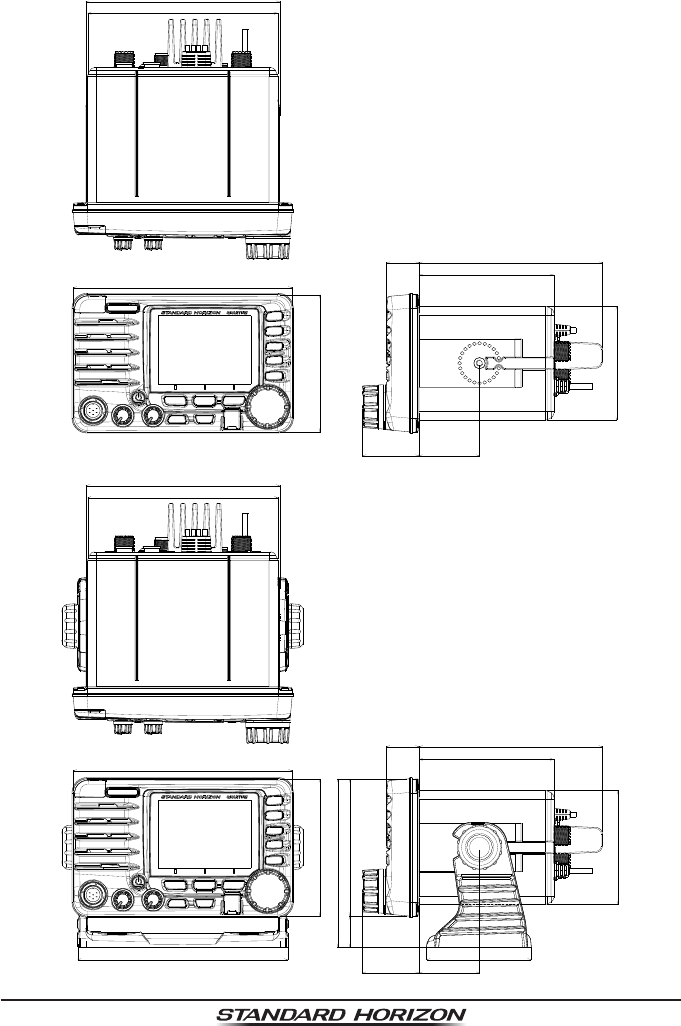
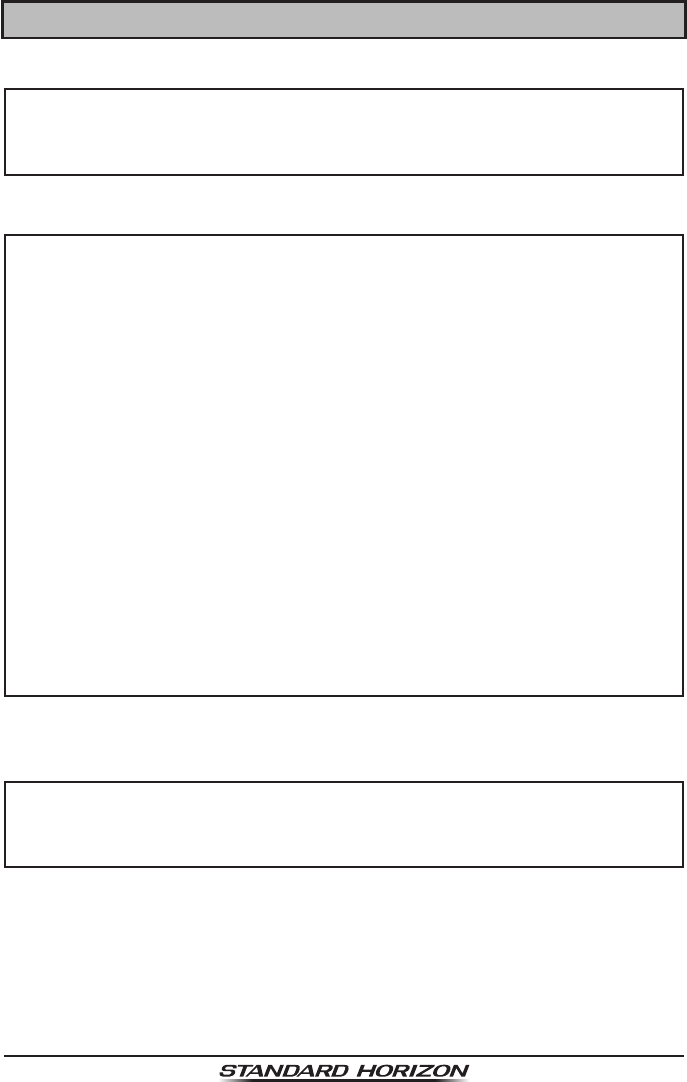
24.7 DIMENSIONS
6.1" (155.4 mm)
6" (152.4 mm)
6.9" (175.5 mm)
6.6" (168.4 mm)
4.3" (110 mm)
4.3" (110 mm)
5.3" (135 mm)
1" (25 mm)
3.6" (91.4 mm)
1" (26.3 mm)5.8" (147 mm)
4.3W" (108 mm)
3.3" (84 mm)
1.9" (48.5 mm)
1.8" (45.4 mm)
6.2" (155.4 mm)
6" (152.4 mm)
6.9" (175.5 mm)
4.33" (110 mm)
3.6" (91.4 mm)
1" (26.3 mm)5.7" (147 mm)
4.3" (108 mm)
1.9" (48.5 mm)
1.8" (45.4 mm)

Page 149
GX6000
25 FCC RADIO LICENSE INFORMATION
Standard Horizon radios comply with the Federal Communication Commission
(FCC) requirements that regulate the Maritime Radio Service.
25.1 STATION LICENSE
An FCC ship station license is no longer required for any vessel traveling in
U.S. waters (except Hawaii) which is under 20 meters in length. However, any
vessel required to carry a marine radio on an international voyage, carrying
a HF single side band radiotelephone or marine satellite terminal is required
to have a ship station license. FCC license forms, including applications for
ship (605) and land station licenses can be downloaded via the Internet at
https://www.fcc.gov/fcc-form-605. To obtain a form from the FCC, call (888)
225-5322.
25.2 RADIO CALL SIGN
Currently the FCC does not require recreational boaters to have a Ship Radio
Station License. The USCG recommends the boats registration number and
the state to be used when calling another vessel.
25.3 CANADIAN SHIP STATION LICENSING
You may need a license when traveling in Canada. If you do need a license
contact their nearest eld ofce or regional ofce or write:
Industry Canada
Radio Regulatory Branch
Attn: DOSP
300 Slater Street
Ottawa, Ontario
Canada, KIA 0C8
25.4 FCC / INDUSTRY CANADA INFORMATION
The following data pertaining to the transceiver is necessary to ll out the
license application.
Type Acceptance ..........................................................................FCC Part 80
Output Power.................................................1 Watt (low) and 25 Watts (high)
Emission ..........................................................................16K0G3E, 16K0G2B
Frequency Range ......................................................156.025 to 163.275 MHz
FCC Type Number .................................................................... K6630593X3D
Industry Canada Type Approval ............................................ 511B-30593X3D
Page 150 GX6000
26 FCC NOTICE
NOTICE
Unauthorized changes or modications to this equipment may void
compliance with FCC Rules. Any change or modication must be
approved in writing by STANDARD HORIZON.
NOTICE
This equipment has been tested and found to comply with the limits for
a Class B digital device, pursuant to Part 15 of the FCC Rules. These
limits are designed to provide reasonable protection against harmful
interference in a residential installation. This equipment generates,
uses and can radiate radio frequency energy and, if not installed and
used in accordance with the instructions, may cause harmful interfer-
ence to radio communications. However, there is no guarantee that
interference will not occur in a particular installation. If this equipment
does cause harmful interference to radio or television reception, which
can be determined by turning the equipment off and on, the user is
encouraged to try to correct the interference by one or more of the
following measures:
z Reorient or relocate the receiving antenna.
z Increase the separation between the equipment and receiver.
z Connect the equipment into an outlet on a circuit different from that
to which the receiver is connected.
z Consult the dealer or an experienced radio/TV technician for help.
WARNING
It is a violation of the rules of the Federal Communications Commission
to input an MMSI that has not been properly assigned to the end user,
or to otherwise input any inaccurate data in this device.

Page 151
GX6000

Page 152 GX6000
THIS DEVICE COMPLIES WITH PART 15 OF THE FCC RULES. OPERATION IS
SUBJECT TO THE FOLLOWING TWO CONDITIONS: (1) THIS DEVICE MAY NOT
CAUSE HARMFUL INTERFERENCE, AND (2) THIS DEVICE MUST ACCEPT ANY
INTERFERENCE RECEIVED, INCLUDING INTERFERENCE THAT MAY CAUSE
UNDESIRED OPERATION.
Changes or modications to this device not expressly approved by YAESU U.S.A.
could void the User’s authorization to operate this device.
This device complies with Industry Canada license-exempt RSS standard(s).
Operation is subject to the following two conditions: (1) this device may not cause
interference, and (2) this device must accept any interference, including interference
that may cause undesired operation of the device.
Le présent appareil est conforme aux CNR d’Industrie Canada applicables aux
appareils radio exempts de licence. L’exploitation est autorisée aux deux conditions
suivantes : (1) l’appareil ne doit pas produire de brouillage, et (2) l’utilisateur de
l’appareil doit accepter tout brouillage radioélectrique subi, même si le brouillage
est susceptible d’en compromettre le fonctionnement.
Under Industry Canada regulations, this radio transmitter may only operate using
an antenna of a type and maximum (or lesser) gain approved for the transmitter by
Industry Canada. To reduce potential radio interference to other users, the antenna
type and its gain should be so chosen that the equivalent isotropically radiated power
(e.i.r.p.) is not more than that necessary for successful communication.
Conformément à la réglementation d’Industrie Canada, le présent émetteur radio
peut fonctionner avec une antenne d’un type et d’un gain maximal (ou inférieur)
approuvé pour l’émetteur par Industrie Canada. Dans le but de réduire les risques
de brouillage radioélectrique à l’intention des autres utilisateurs, il faut choisir le
type d’antenne et son gain de sorte que la puissance isotrope rayonnée quivalente
(p.i.r.e.) ne dépassepas l’intensité nécessaire à l’établissement d’une communication
satisfaisante.
This radio transmitter (identify the device by certication number, or model number
if Category II) has been approved by Industry Canada to operate with the antenna
types listed below with the maximum permissible gain and required antenna
impedance for each antenna type indicated. Antenna types not included in this list,
having a gain greater than the maximum gain indicated for that type, are strictly
prohibited for use with this device.
Le présent émetteur radio (identier le dispositif par son numéro de certication ou
son numéro de modèle s’il fait partie du matériel de catégorie I) a été approuvé par
Industrie Canada pour fonctionner avec les types d’antenne énumérés ci-dessous
et ayant un gain admissible maximal et l’impédance requise pour chaque type
d’antenne. Les types d’antenne non inclus dans cette liste, ou dont le gain est
supérieur au gain maximal indiqué, sont strictement interdits pour l’exploitation de
l’émetteur. l’établissement d’une communication satisfaisante.
CAN ICES-3 (B) / NMB-3 (B)
Page 153
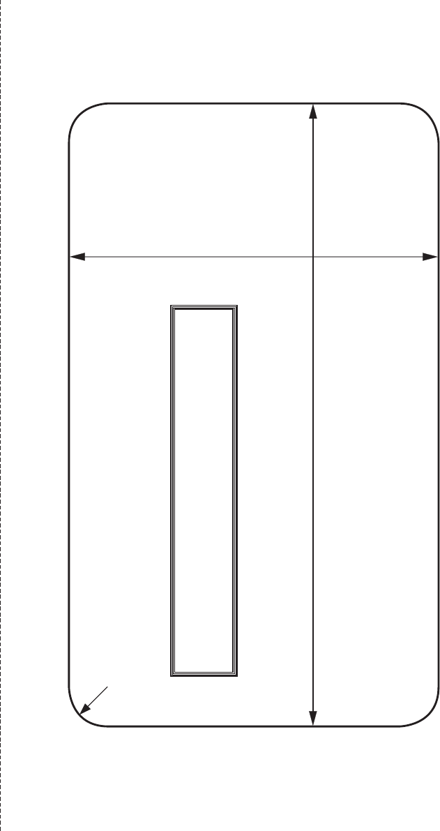
TEMPLATE for the GX6000
Use this template to mark the location where the
rectangular hole for the ush mount is to be cut.
R10
158 mm
94 mm
cut here