Yaesu Musen 30593X3D MOBILE MARINE TRANSCEIVER User Manual GX6000 Owner s Manual
Yaesu Musen Co., Ltd. MOBILE MARINE TRANSCEIVER GX6000 Owner s Manual
Contents
OM User Manual 1
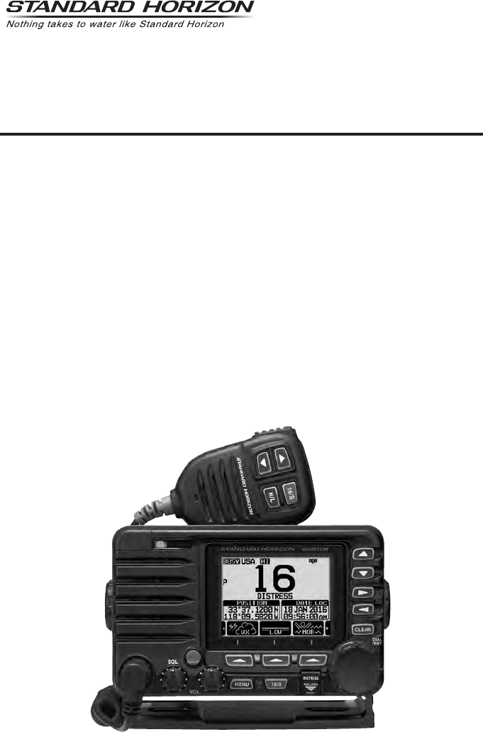
QUANTUM AIS GX6000
25 Watt VHF/FM
Marine Transceiver
Owner’s Manual
zCapable of connecting two optional wired RAM4 or one wired RAM4 and up to four Wireless
RAM4W remote access microphones using SCU-31 wireless access point
zIntegrated NMEA 2000 interface supporting all PGNs for Navigation, GPS, AIS and DSC functions
zIntegrated Dual Channel AIS (Automatic Identication System) receiver
zGPS Compass, Waypoint and GPS status pages
zDual Zone 25W PA / Loud Hailer with preprogrammed horn, siren, fog signals and listen back
zSubmersible IPX8 (5 feet or 1.5 meters for 30 minutes)
zIntegrated 32 Code Voice Scrambler and 4 Code Voice Scrambler
zAIS / AIS SART target display: MMSI, Call Sign, Ship Name, BRG, DST, SOG and COG
zFront panel microphone can be connected to rear panel and extended 20 feet using MEK-4
mic extension kit
zProgrammable CPA or TCPA collision avoidance alarms
zAdvanced 80 dB commercial Grade Receiver with Local / Distance Attenuator
zIntercom feature allows you to communicate between the radio, RAM4 and Wireless RAM4W
microphones
zIntegrated Voice Recorder to play back up to two minutes of RX receive audio

TABLE OF CONTENTS
Quick Reference Guide ...................................... 2
1 GENERAL INFORMATION ............................ 3
2 PACKING LIST ............................................... 4
3 OPTIONAL ACCESSORIES .......................... 4
4 ONLINE WARRANTY REGISTRATION
(in USA or Canada only) ............................... 4
5 GETTING STARTED ...................................... 5
5.1 PROHIBITED COMMUNICATIONS ............................. 5
5.2 ABOUT VHF RADIO .................................................... 5
5.3 SELECTING AN ANTENNA ......................................... 5
5.4 COAXIAL CABLE ......................................................... 6
5.5 DISTRESS AND HAILING (CHANNEL 16) .................. 6
5.6 CALLING ANOTHER VESSEL (CHANNEL 16 OR 9) ... 7
5.7 MAKING TELEPHONE CALLS .................................... 8
5.8 BRIDGE CHANNELS 13 AND 67 ................................ 8
5.9 AUTOMATED RADIO CHECK SERVICE .................... 8
5.10 WHAT IS THE RANGE FOR AIS RECEIVERS? .......... 9
5.11 Accuracy of COG* ........................................................ 9
6 CONTROLS AND INDICATORS .................. 10
6.1 FRONT PANEL .......................................................... 10
6.2 MICROPHONE .......................................................... 12
6.3 REAR PANEL ............................................................. 14
7 INSTALLATION ............................................ 16
7.1 SAFETY / WARNING INFORMATION ....................... 16
7.2 LOCATION ................................................................. 16
7.3 MOUNTING THE RADIO ........................................... 16
7.4 ELECTRICAL CONNECTIONS .................................. 18
7.5 CONNECTION OF EXTERNAL DEVICES
TO THE RADIO ... 19
7.6 INITIAL SETUP REQUIRED WHEN TURNING
ON THE POWER FOR THE FIRST TIME ... 26
7.7 CHECKING GPS SIGNAL (GPS STATUS DISPLAY) .... 28
7.8 GPS CONFIGURATION ............................................. 29
8 BASIC OPERATION ..................................... 32
8.1 TURNING ON AND OFF THE TRANSCEIVER ......... 32
8.2 RECEPTION .............................................................. 32
8.3 TRANSMISSION ........................................................ 32
8.4 BASIC OPERATION OF THE MENU MODE ............. 33
8.5 TRANSMIT TIME-OUT TIMER (TOT) ........................ 34
8.6 SIMPLEX/DUPLEX CHANNEL USE .......................... 34
8.7 USA, INTERNATIONAL, AND CANADA MODE ........ 35
8.8 NOAA WEATHER CHANNELS .................................. 35
8.9 MULTI WATCH (TO PRIORITY CHANNEL) .............. 37
8.10 SCANNING ................................................................ 38
8.11 PRESET CHANNELS: INSTANT ACCESS ................ 40
8.12 MOB OPERATION ..................................................... 41
8.13 PA/FOG OPERATION ................................................ 42
8.14 INTERCOM OPERATION .......................................... 45
8.15 VOICE SCRAMBLER ................................................. 45
8.16 DEMO MODE ............................................................. 46
9 GPS OPERATION ........................................ 47
9.1 DISPLAYING POSITION INFORMATION .................. 47
9.2 CHECKING GPS STATUS ......................................... 47
9.3 GPS LOGGER OPERATION ..................................... 48
10 DIGITAL SELECTIVE CALLING (DSC) ....... 49
10.1 GENERAL .................................................................. 49
10.2 DSC DISTRESS ALERT ............................................ 50
10.3 ALL SHIPS CALL ....................................................... 54
10.4 INDIVIDUAL CALL ..................................................... 56
10.5 GROUP CALL ............................................................ 62
10.6 POSITION REQUEST ................................................ 67
10.7 POSITION REPORT .................................................. 71
10.8 POLLING CALL .......................................................... 75
10.9 AUTO POSITION POLLING ...................................... 77
10.10 DSC TEST .................................................................. 79
10.11 DSC LOG OPERATION ............................................. 81
10.12 DSC LOOP BACK OPERATION ................................ 83
11 NAVIGATION ................................................ 84
11.1 WAYPOINT OPERATION ........................................... 84
11.2 ROUTING OPERATION ............................................. 88
12 GM OPERATION .......................................... 92
12.1 SETTING UP GM OPERATION ................................. 92
12.2 STARTING GM OPERATION ..................................... 94
13
AUTOMATIC IDENTIFICATION SYSTEM (AIS)
... 96
13.1 GENERAL .................................................................. 96
13.2 AIS OPERATION ....................................................... 97
13.3 AIS SETUP .............................................................. 100
14 NMEA 2000 SETUP ................................... 102
14.1 SELECT DEVICE ..................................................... 102
14.2 DEVICE NUMBER ................................................... 102
14.3 SYSTEM NUMBER .................................................. 103
14.4 SUMMARY OF THE NMEA 2000 SETUP ................ 103
14.5 COMPATIBLE NMEA 2000 PGN LIST ..................... 103
15 CONFIGURATION SETUP ......................... 105
15.1 DISPLAY MODE ....................................................... 105
15.2 DIMMER ADJUSTMENT .......................................... 105
15.3 DISPLAY CONTRAST .............................................. 105
15.4 KEY BEEP ................................................................ 106
15.5 FOG ALERT TONE FREQUENCY ........................... 106
15.6 LISTEN BACK .......................................................... 106
15.7 STATION NAME ....................................................... 107
15.8 SOFT KEYS ............................................................. 108
15.9 RESET ..................................................................... 110
15.10 SUMMARY OF THE CONFIGURATION SETUP ..... 110
16 CHANNEL FUNCTION SETUP .................. 111
16.1 CHANNEL GROUP .................................................. 111
16.2 WEATHER ALERT ................................................... 111
16.3 SCAN MEMORY ...................................................... 111
16.4 SCAN TYPE ............................................................. 111
16.5 SCAN RESUME ....................................................... 111

TABLE OF CONTENTS
16.6 MULTI WATCH ......................................................... 112
16.7 PRIORITY CHANNEL .............................................. 112
16.8 SUB CHANNEL ........................................................ 112
16.9 CHANNEL NAME ..................................................... 112
16.10 NOISE CANCELLATION .......................................... 113
16.11 AUDIO FILTER OPERATION ................................... 114
16.12 RX RECORDER ....................................................... 114
16.13 SCRAMBLER SETUP .............................................. 116
16.14 SUMMARY OF THE CANNEL FUNCTION SETUP .... 117
17 DSC SETUP ............................................... 118
17.1 INDIVIDUAL DIRECTORY ....................................... 118
17.2 INDIVIDUAL REPLY ................................................. 118
17.3 INDIVIDUAL ACKNOWLEDGMENT ........................ 118
17.4 INDIVIDUAL RINGER .............................................. 118
17.5 GROUP DIRECTORY .............................................. 118
17.6 POSITION REPLY .................................................... 119
17.7 AUTO POSITION POLLING .................................... 119
17.8 AUTO POSITION INTERVAL ................................... 119
17.9 AUTO CHANNEL CHANGE ..................................... 119
17.10 NO ACTION TIMER ................................................. 120
17.11 WAIT TIME FOR POSITION FIX .............................. 120
17.12 DSC BEEP ............................................................... 120
17.13 SUMMARY OF THE DSC SETUP MENU ................ 120
18 GPS SETUP ............................................... 122
18.1 ORDER OF PRIORITY ............................................ 122
18.2 COMPASS DIRECTION ........................................... 122
18.3 LOCATION FORMAT ............................................... 122
18.4 TIME OFFSET ......................................................... 123
18.5 TIME AREA .............................................................. 123
18.6 TIME FORMAT ......................................................... 123
18.7 UNITS OF MEASURE .............................................. 123
18.8 MAGNETIC VARIATION .......................................... 123
18.9 NMEA 0183 IN/OUT ................................................. 124
18.10 Position Data Output ................................................ 125
18.11 OPTION GPS UNIT ................................................. 126
18.12 SUMMARY OF THE GPS SETUP ........................... 128
19
SSM-70H (RAM4) REMOTE MIC OPERATION
... 130
19.1 REMOTE MIC CONTROLS ..................................... 130
19.2 RAM4 SOFT KEY ASSIGNMENT ............................ 132
20 CONNECTING A USB DATA TERMINAL
TO THE PC ... 134
21 MAINTENANCE ......................................... 134
21.1 REPLACEMENT PARTS .......................................... 135
21.2 FACTORY SERVICE ................................................ 135
21.3 TROUBLESHOOTING CHART ................................ 136
22 CHANNEL ASSIGNMENTS ....................... 137
23 WARRANTY ............................................... 143
24 SPECIFICATIONS ...................................... 146
24.1 GENERAL ................................................................ 146
24.2 TRANSMITTER ........................................................ 146
24.3 RECEIVER (for Voice and DSC) .............................. 146
24.4 RECEIVER (for AIS) ................................................. 147
24.5 NMEA INPUT/OUTPUT ............................................ 147
24.6 SCU-31 EXTERNAL GPS ANTENNA (Optional) ..... 147
24.7 DIMENSIONS .......................................................... 148
25 FCC RADIO LICENSE INFORMATION ..... 149
25.1 STATION LICENSE .................................................. 149
25.2 RADIO CALL SIGN .................................................. 149
25.3 CANADIAN SHIP STATION LICENSING ................. 149
25.4 FCC / INDUSTRY CANADA INFORMATION ........... 149
26 FCC NOTICE .............................................. 150
TEMPLATE for the GX6000 ..............................153
Page 2 GX6000
Quick RefeRence Guide
The GX6000 is equipped with the E2O (Easy-To-Operate) menu system. Basic
operation may be accomplished by following the procedure below:
Press and hold the key to turn on or off the radio.
The MODE/STATUS indicator indicates the status of the transceiver.
Rotate the SQL knob clockwise to squelch or counterclockwise to
un-squelch the radio.
Rotate the VOL knob to adjust the speaker audio volume.
Press the MENU key to access MENU.
Press the 16/S key on the radio or the microphone to select channel 16.
Press and hold the 16/S key on the radio or the microphone to select sub
channel. Press again to revert to the last selected channel.
Activates a DSC distress call. Lift the red cover, press the DISTRESS once,
then press and hold until the radio alarms.
These three programmable soft keys can be customized through the setup
menu to quickly access advanced functions of the radio. Press the ►/◄
key to switch the function of these keys, display the key functions at the
bottom of the display.
Press the ▲/▼ key (or press the microphone’s ▲/▼ keys) to select the
operating channel. While the MENU screen is displayed, press the key to
slide the on-screen menu upward/downward.
Press the ►/◄ key to switch the function menu. While the MENU screen is
displayed, press the key to slide the on-screen menu to the right/left side.
Press the CLEAR key to cancel a function or menu selection.
While the normal screen is displayed, rotate the DIAL/ENT knob to select
your desired channel. While the MENU screen is displayed, rotate the knob
to select your desired menu item.
To transmit: place your mouth about 1/2 inch away from Mic hole and speak
in a normal voice level while pressing the PTT switch.
Press the H/L key to toggle the transmit power between High (25W) and
Low (1W).

Page 3
GX6000
1 GENERAL INFORMATION
The STANDARD HORIZON GX6000 Marine VHF/FM Marine transceiver is
designed to be used in USA, International, and Canadian Marine bands. The
GX6000 can be operated from 11 to 16 VDC and has a switchable RF output
power of 1 watt or 25 watts.
The GX6000 integrates a dual channel AIS (Automatic Identication System)
receiver to display class A and B AIS vessel information (MMSI, Call Sign, Ship
Name, BRG, DST, SOG and COG) directly on the LCD display. The GX6000
has a separate AIS antenna connection to ensure that your will be able to
receive AIS signals while transmitting VHF communications. The GX6000 is
also capable of entering and saving up to 250 waypoints, which may be selected
and navigated to by using a unique navigation compass display. The GX6000
allows you to contact an AIS ship directly using DSC, show your vessels position
in relation to AIS targets and alert you when an AIS ship may be approaching
too close to your location via the Closest Point of Approach (CPA) Alarm or
Time to Closest Point of Approach (TCPA) Alarm.
The GX6000 is capable of DSC (Digital Selective Calling) ITU-R M.493 Class
D operation. Class D operation allows continuous receiving of Digital Selective
Calling functions on channel 70 even if the radio is receiving a call. The GX6000
operates on all currently-allocated marine channels which are switchable for
use with USA, International, or Canadian regulations. Emergency channel 16
can be immediately selected from any channel by pressing the red 16/S key.
NOAA weather channel can also be accessed immediately by pressing the
[WX] soft key.
Other features of the GX6000 includes: Noise canceling function for transmit
and receive audio, NMEA 2000 compatibility, high expandability, integrated
voice recorder to play back up to two minutes of RX receive audio, speaker
microphone, dual zone 25 W PA/Loud hailer with preprogrammed fog signals
and listen back, capable of being connected to two optional wired RAM4 or
one wired RAM4 and four Wireless RAM4W*1 remote access microphones,
allowing full control of all VHF, DSC and hailer functions remotely including
an intercom feature allowing you to communicate between the radio, RAM4
and Wireless RAM4W microphones, scanning, priority scanning, submersible
speaker microphone, high and low voltage warning, and GPS repeatability. (*1
requires SCU-30 Wireless Access Port)

Page 4 GX6000
2 PACKING LIST
When the package containing the transceiver is rst opened, please check it
for the following contents:
Transceiver GX6000
Speaker Microphone
DC Power Cord
Mounting Bracket and Hardware
Owner’s Manual
DSC Warning Sticker
USB Cable (Type USB “A” plug to Type USB micro “B” plug) T9101606
3 OPTIONAL ACCESSORIES
Flush-Mount Bracket ....................................................................... MMB-84
Remote-Access Microphone (RAM4 Mic) ....................................... SSM-70H
RAM4W Wireless Remote Access Microphone ............................... SSM-71H
Wireless Access Point ..................................................................... SCU-30
23 Feet Extension Cable for SSM-70H (RAM4) Microphone .......... CT-100
20 Feet Microphone Extension Kit (for connection to rear panel) ... MEK-4
External Loud Speaker .................................................................... MLS-300
5” Round 30 Watt Hail/PA Horn ....................................................... 220SW
5” × 8” Rectangular 40 Watt Hail/PA Horn ....................................... 240SW
External GPS Antenna with 49 Feet of Cable .................................. SCU-31
4 ONLINE WARRANTY REGISTRATION
(in USA or Canada only)
Please visit www.standardhorizon.com to register the GX6000 Marine VHF. It
should be noted that visiting the website from time to time may be benecial
to you, as new products are released they will appear on the STANDARD
HORIZON website.
PRODUCT SUPPORT INQUIRIES
If you have any questions or comments regarding the use of the GX6000, you
can visit the STANDARD HORIZON website to send an E-Mail or contact the
Product Support team at (800) 767-2450 M-F 8:00-5:00 PST.

Page 5
GX6000
5 GETTING STARTED
5.1 PROHIBITED COMMUNICATIONS
The FCC prohibits the following communications:
• False distress or emergency messages:
• Messages to “any boat” except in emergencies and radio tests;
• Messages to or from a vessel on land;
• Transmission while on land;
• Obscene, indecent, or profane language (potential ne of $10,000).
5.2 ABOUT VHF RADIO
The radio frequencies used in the VHF marine band lie between 156 and 158
MHz with some shore stations available between 161 and 163 MHz. The marine
VHF band provides communications over distances that are essentially “line of
sight” (VHF signals do not travel well through objects such as buildings, hills or
trees). Actual transmission range depends much more on antenna type, gain
and height than on the power output of the transmitter. On a xed mount 25
W radio transmission expected distances can be greater than 15 miles, for a
portable 5 W radio transmission the expected distance can be greater than 5
miles in “line of sight”.
5.3 SELECTING AN ANTENNA
Marine antennas are made to radiate signals equally in all horizontal directions,
but not straight up. The objective of a marine antenna is to enhance the signal
toward the horizon. The degree to which this is accomplished is called the
antenna’s gain. It is measured in decibels (dB) and is one of the major factors
in choosing an antenna. In terms of effective radiated power (ERP), antennas
are rated on the basis of how much gain they have over a theoretical antenna
with zero gain. A 3-foot, 3 dB gain antenna represents twice as much gain over
the imaginary antenna.
Typically, a 3-foot 3 dB gain stainless steel whip is used on a sailboat mast.
The longer 8-foot 6 dB berglass whip is primarily used on power boats that
require the additional gain.
3dB 6dB 9dB
Page 6 GX6000
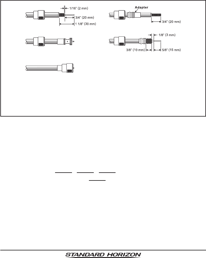
5.4 COAXIAL CABLE
VHF antennas are connected to the transceiver by means of a coaxial cable
– a shielded transmission line. Coaxial cable is specied by its diameter and
construction.
For runs less than 20 feet, RG-58/U, about 1/4 inch in diameter is a good choice.
For runs over 20 feet but less than 50 feet, the larger RG-8X or RG-213/U should
be used for cable runs over 50 feet RG-8X should be used. For installation of
the connector onto the coaxial cable refer to the gure below.
To get your coax cable through a tting and into your boat’s interior,
you may have to cut off the end plug and reattach it later. You can do
this if you follow the directions that come with the connector. Be sure
to make good soldered connections.
5.5 DISTRESS AND HAILING (CHANNEL 16)
Channel 16 is known as the Hail and Distress Channel. An emergency may be
dened as a threat to life or property. In such instances, be sure the transceiver
is on and set to CHANNEL 16. Then use the following procedure:
1. Press the microphone push-to-talk switch and say “Mayday, Mayday,
Mayday. This is , , ” (your vessel’s name).
2. Then repeat once: “Mayday, ” (your vessel’s name).
3. Now report your position in latitude/longitude, or by giving a true or magnetic
bearing (state which) to a well-known landmark such as a navigation aid
or geographic feature such as an island or harbor entry.
4. Explain the nature of your distress (sinking, collision, aground, re, heart
attack, life-threatening injury, etc.).
5. State the kind of assistance your desire (pumps, medical aid, etc.).
6. Report the number of persons aboard and condition of any injured.
7. Estimate the present seaworthiness and condition of your vessel.

Page 7
GX6000
8. Give your vessel’s description: length, design (power or sail), color and other
distinguishing marks. The total transmission should not exceed 1 minute.
9. End the message by saying “OVER”. Release the microphone switch and
listen.
10. If there is no answer, repeat the above procedure. If there is still no response,
try another channel.
NOTE
The GX6000 has the DSC Distress calling, that can transmit a distress
call digitally to all ships with compatible DSC radios. Refer to section
“10 DIGITAL SELECTIVE CALLING (DSC)”.
5.6 CALLING ANOTHER VESSEL (CHANNEL 16 OR 9)
Channel 16 may be used for initial contact (hailing) with another vessel.
However, its most important use is for emergency messages. This channel
must be monitored at all times except when actually using another channel.
It is monitored by the U.S. and Canadian Coast Guards and by other vessels.
Use of channel 16 for hailing must be limited to initial contact only. Call-
ing should not exceed 30 seconds, but may be repeated 3 times at 2-minute
intervals. In areas of heavy radio trafc, congestion on channel 16 resulting
from its use as a hailing channel can be reduced signicantly in U.S. waters
by using channel 9 as the initial contact (hailing) channel for non-emergency
communications. Here, also, calling time should not exceed 30 seconds but
may be repeated 3 times at 2-minute intervals.
Prior to making contact with another vessel, refer to the channel charts in this
manual, and select an appropriate channel for communications after initial
contact. For example, Channels 68 and 69 of the U.S. VHF Charts are some
of the channels available to non-commercial (recreational) boaters. Monitor
your desired channel in advance to make sure you will not be interrupting
other trafc, and then go back to either channel 16 or 9 for your initial contact.
When the hailing channel (16 or 9) is clear, press the PTT switch on the mic and
state the name of the other vessel you wish to call and then “this is” followed by
the name of your vessel and your Station License (Call Sign) then release the
PTT switch on the mic. When the other vessel returns your call, immediately
request another channel by pressing the PTT switch on the mic and saying “go
to,” the number of the other channel, say “over” and release the PTT switch on
the mic. Then switch to the new channel. When the new channel is not busy,
call the other vessel.

Page 8 GX6000
After a transmission, say “over,” and release the microphone’s push-to-talk
(PTT) switch. When all communication with the other vessel is completed, end
the last transmission by stating your Call Sign and the word “out.” Note that
it is not necessary to state your Call Sign with each transmission, only at the
beginning and end of the contact.
Remember to return to Channel 16 when not using another channel. Some
radios automatically monitor Channel 16 even when set to other channels or
when scanning.
5.7 MAKING TELEPHONE CALLS
To make a radiotelephone call, use a channel designated for this purpose.
The fastest way to learn which channels are used for radiotelephone trafc
is to ask at a local marina. Channels available for such trafc are designated
Public Correspondence channels on the channel charts in this manual. Some
examples for USA use are Channels 24, 25, 26, 27, 28, 84, 85, 86, and 87. Call
the marine operator and identify yourself by your vessel’s name. The marine
operator will then ask you how you will pay for the call (telephone credit card,
collect, etc.) and then link your radio transmission to the telephone lines.
The marine telephone company managing the VHF channel you are using may
charge a link-up fee in addition to the cost of the call.
5.8 BRIDGE CHANNELS 13 AND 67
Channel 13 is used at docks, bridges and by vessels maneuvering in port.
Messages on this channel must concern navigation only, such as meeting and
passing in restricted waters.
Channel 67 is used for navigational trafc between vessels.
By regulation, power is normally limited to 1 Watt on these channels. Your radio
is programmed to automatically reduce power to this limit on these channels.
However, in certain situations it may be necessary to temporarily use a higher
power. See Page 33 for means to temporarily override the low-power limit
on these two channels.
5.9 AUTOMATED RADIO CHECK SERVICE
In areas across the country, Sea Tow offers boaters a way to conduct radio
checks. To use Sea Tow’s free Automated Radio Check service, simply tune
your VHF radio to the appropriate channel for your location and conduct a
radio check as you typically would. Upon releasing your radio’s microphone,
the system will play an automated message and relay your transmission back
to you, thereby letting you know how your signal will sound to other boaters.
The Automated Radio Check Service is currently available in the areas listed below.
Page 9
GX6000
West Coast Sea Tow Newport/LA - Ch. 27
Sea Tow San Diego - Ch. 27
Northeast Sea Tow Portland-Midcoast (Maine) - Ch. 27
Sea Tow Boston - Ch. 27
Sea Tow South Shore (Mass.) - Ch. 28
Sea Tow Rhode Island - Ch. 24
Sea Tow Eastern Long Island - Ch. 27
Sea Tow Huntington (N.Y.) - Ch. 27
Sea Tow Manasquan (N.J.) - Ch. 28
Mid-Atlantic Sea Tow Northern Chesapeake (Md.) - Ch. 28
Sea Tow Central Chesapeake (Md.) - Ch. 27
Sea Tow Hampton Roads (Va.) - Ch. 28
North Carolina Sea Tow Wrightsville Beach - Ch. 28
Sea Tow Ocean Isle Beach - Ch. 28
Florida Sea Tow Sebastian - Ch. 28
Sea Tow Fort Lauderdale - Ch. 27
Sea Tow Charlotte Harbor - Ch. 24
Sea Tow Tampa Bay - Ch. 27
Sea Tow Horseshoe Beach - Ch. 27
Sea Tow Carrabelle/St. Marks - Ch. 27
Sea Tow Pensacola/Orange Beach (Ala.) - Ch. 27
5.10 WHAT IS THE RANGE FOR AIS RECEIVERS?
Since AIS uses similar frequencies as a marine VHF radio, it has similar radio
reception capabilities - which are basically line of sight. This means that the
higher the VHF antenna is mounted, the greater the reception area will be.
Reception from Class A vessels that are 20 or even 30 miles away on open
water is not uncommon as their antennas are mounted high off the water. Class
B transponders use lower power for transmissions; therefore, you can expect
Class B vessels to be acquired when they are 5 to 10 miles away.
NOTE
The GX6000 require two separate marine VHF antennas; one antenna
for VHF and a second antenna for AIS.
For additional information on AIS visit the USCG website:
<http://www.navcen.uscg.gov/marcomms/ais.htm>
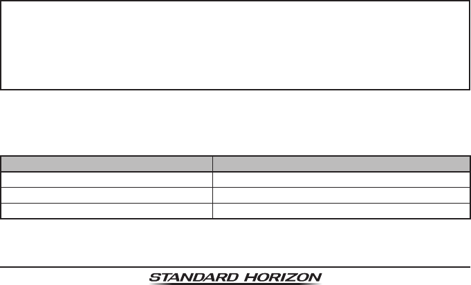
5.11 Accuracy of COG*
The error in the COG (the path of the antenna position over ground) due to the
actual ship’s speed over ground shall not exceed the following values:
Speed range (knots) Accuracy of COG output to user
0 to ≤1 knot Unreliable or not available
>1 to ≤17 knots ±3°
>17 knots ±1°
* Only when the SCU-31 external GPS antenna connected.
Page 10 GX6000
6 CONTROLS AND INDICATORS
This section denes each control of the transceiver. See illustration below for
location of controls. For detailed operating instructions refer to chapter 8 of
this manual.
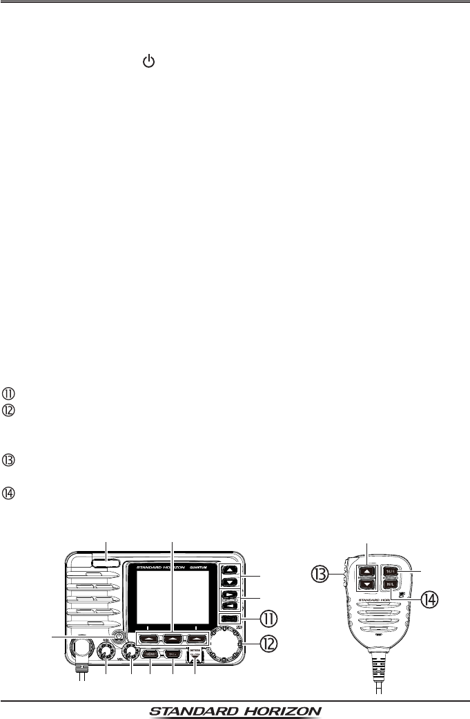
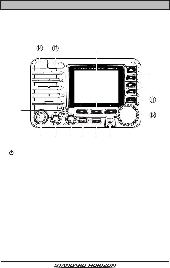
6.1 FRONT PANEL
(Power) key
Press and hold to toggle the radio on or off. When the power is turned on,
the transceiver is set to the last selected channel.
MIC Connector
Connects the supplied speaker microphone.
SQL knob (Squelch control)
Adjusting this control clockwise, sets the point at which random noise on
the channel does not activate the audio circuits but a received signal does.
This point is called the squelch threshold. Further adjustment of the squelch
control will degrade reception of wanted transmissions.
VOL knob (Volume control)
Adjusts the audio volume level.
Clockwise rotation of this knob increases the internal and speaker micro-
phone volume.
Secondary uSe
When in the PA or Fog mode, controls the listen-back volume.

Page 11
GX6000
MENU key
Press to access MENU. For details, refer to section “8.4 BASIC OPERA-
TION OF THE MENU MODE”.
16/S key
Pressing this key immediately recalls channel 16 from any channel loca-
tion. Holding down this key selects the SUB channel (The default setting is
channel 9). Pressing this key again reverts to the previous selected working
channel.
DISTRESS key
Used to send a DSC Distress Call. To send the distress call, refer to section
“10.2.1 Transmitting a DSC Distress Alert”.
Soft keys
The 3 programmable soft keys can be customized by the Setup Menu mode
described in section “15.8 SOFT KEYS”.
▲/▼ key
These keys are used to change the operating channel. The Up/Down keys
on the microphone can also be used to change the operating channel.
Press the key momentarily, the channel increases/decreases one step.
Holding the key, the channel increases/decreases continuously.
Secondary uSe
While the MENU screen is displayed, press the key to slide the on-screen
menu upward/downward.
►/◄ key
Press these keys to switch the function of soft keys.
Secondary uSe
While the MENU screen is displayed, press the key to slide the on-screen
menu to the right/left side.
CLEAR key
Press this key to cancel a menu selection.
DIAL/ENT knob
While the normal screen is displayed, rotate the DIAL/ENT knob to select
your desired channel. While the MENU screen is displayed, rotate the knob
to select your desired menu item.
Secondary uSe
Press this knob to enter a selection in the MENU.
Page 12 GX6000
MODE/STATUS indicator
Indicates the radio status with the four colors on the three positions of the
mode/status indicator.
Position Color Description
Left
Blue AIS-Board Working
Purple Receiving MSG23
Red AIS-Board Failed
Right
Green AIS Receiving (registered MMSI)
Orange AIS Receiving (unregistered MMSI)
Red Receive Error
DATA jack
Use the USB micro type B jack to congure the transceiver settings and
download the GPS logger data.
Note: When the DATA jack is securely covered with rubber cap, the GX6000
meets the waterproong performance.
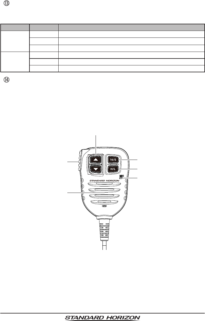
6.2 MICROPHONE
PTT (Push-To-Talk) switch
When in radio mode and the PTT switch is pressed, the transmitter is
enabled for voice communications to another vessel.
When PA mode is selected, pressing the PTT switch allows your voice to
be amplied and supplied to a connected PA horn.

Page 13
GX6000
When an optional RAM4 and RAM4W mic is connected and intercom mode
is selected, pressing the PTT switch enables voice communications from
the GX6000 to the RAM4 and RAM4W second station microphone.
Microphone speaker
Audio heard through internal radio speaker is heard through the speaker
microphone.
▲/▼ key
These keys on the microphone are used to select channels and to choose
menu items.
16/S key
Pressing this key immediately selects channel 16 from any channel loca-
tion. Holding down this key selects the SUB channel (The default setting is
channel 9). Pressing this key again reverts to the previous selected working
channel.
H/L key
Press this key to toggle between 25 W (High) and 1 W (Low) power. When
the TX output power is set to “Low” while the transceiver is on channel 13
or 67, the output power will temporarily switch from “Low” to “High” power
until the PTT switch of the microphone is released. This key is not available
on transmit inhibited and low power only channels.
Microphone
The internal microphone transmits your voice reducing background noise
using Clear Voice Noise Reduction Technology.
Note: Position your mouth about 1/2” (1.5 cm) away from the microphone
hole and speak in a normal voice.
Page 14 GX6000
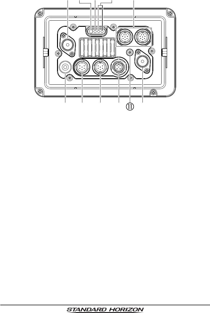
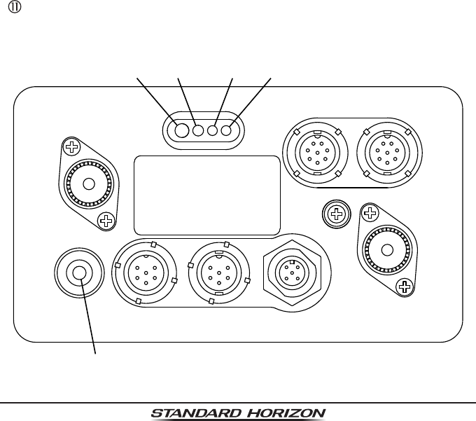
6.3 REAR PANEL
VHF ANT jack (VHF antenna jack)
Connects an antenna to the transceiver. Use a marine VHF antenna with
an impedance of 50 ohms.
Note: This ANT jack is used to marine voice channel.
AIS ANT jack (AIS antenna jack)
Connects an antenna to the AIS receiver. Use a marine VHF antenna with
an impedance of 50 ohms.
PA Speaker Connection Cable (Orange, Yellow, Green & Blue)
Connects the GX6000 to PA speakers. See section “3 OPTIONAL ACCES-
SORIES” for a list of optional STANDARD HORIZON Speakers.
Green: PA1 Speaker (+)
Blue: PA1 Speaker (−)
Orange: PA2 Speaker (+)
Yellow: PA2 Speaker (−)
EXTERNAL Speaker Connection Cable (Red & White)
Connects the GX6000 to an optional external speaker. Refer to section “3
OPTIONAL ACCESSORIES” for a list of optional STANDARD HORIZON
Speakers.
Red: External Speaker (+)
White: External Speaker (−)
DC Input Cable
Connects the radio to a DC power supply capable of delivering 11 to 16 VDC.
Page 15
GX6000
RAM-1/RAM-2 Remote Access Microphone Connectors
Connects the GX6000 to the SSM-70H (RAM4) Remote Station Micro-
phone or SCU-30 Wireless Access Point for use with up to four SSM-71H
(RAM4W) wireless microphones. Refer to section “19 SSM-70H (RAM4)
REMOTE MIC OPERATION” for details.
NMEA 0183 In/Out & NMEA 0183-HS OUT Connection Cable (Blue, Green,
Gray, Brown, Yellow & White)
Connects the GX6000 to a GPS chart plotter. Refer to section “7.5 CONNEC-
TION OF EXTERNAL DEVICES TO THE RADIO”.
Rear MIC Connector
Connects the supplied hand microphone if desired. This connector provides
the same function as that on the front panel and allows remote use of the
microphone by using the optional MEK-4 (microphone extension kit).
GPS ANT Connector (White)
Connects the optional SCU-31 external GPS antenna.
NMEA 2000 Connector (Black)
Connects to the NMEA 2000 network.
GND Terminal (Ground Terminal)
Connects the GX6000 to ships ground, for safe and optimum performance.
Use the screw supplied with the GX6000 only.
GPS ANT AIS ANT
NMEA 2000REAR MIC
GND
RAM-1 RAM-2
NMEA 0183
VHF ANT
DC- DC+PA SP EXT SP
Page 16 GX6000
7 INSTALLATION
7.1 SAFETY / WARNING INFORMATION
This radio is restricted to occupational use, work related operations only where
the radio operator must have the knowledge to control the exposure conditions of
its passengers and bystanders by maintaining the minimum separation distance
of 3 feet (1 m). Failure to observe these restrictions will result in exceeding the
FCC RF exposure limits.
Antenna Installation:
The antenna must be located at least 3 feet (1 m) away from passengers in
order to comply with the FCC RF exposure requirements.
7.2 LOCATION
The radio can be mounted at any angle. Choose a mounting location that:
• complies with the compass safe distances shown in the table below to
prevent interference to a magnetic compass
Transceiver Unit 1.0 m
Handset 0.5 m
• provides accessibility to the front panel controls
• allows connection to a power source and antennas
• has nearby space for installation of a microphone hanger
• is at least 3 feet (1 m) away from the radio’s antenna
• the signal from the GPS satellite can receive sufciently
Note: To insure the radio does not affect the compass or radios performance
is not affected by the antenna location, temporarily connect the radio in the
desired location and:
a. Examine the compass to see if the radio causes any deviation
b. Connect the antenna and key the radio. Check to ensure the radio is
operating correctly by requesting a radio check.
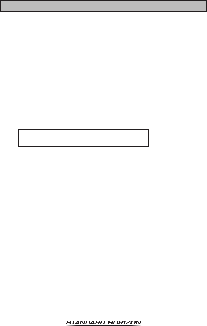
7.3 MOUNTING THE RADIO
7.3.1 Supplied Mounting Bracket
The supplied mounting bracket allows overhead or desktop mounting.
Use a 13/64” (5.2 mm) bit to drill the holes to a surface which is more 0.4” (10
mm) thick and can support more than 3.3 lbs (1.5 kg) and secure the bracket
with the supplied screws, spring washers, at washers, and nuts.
Page 17
GX6000
Desktop Mounting Overhead Mounting
7.3.2 Optional MMB-84 Flush Mount Bracket
1. Use the template (page 153) to mark the location where the rectangular
hole is to be cut. Conrm the space behind the dash or panel is deep enough
to accommodate the transceiver (at least 6.7” (17 cm) deep).
There should be at least 1/2” (1.3 cm) between the transceivers heatsink
and any wiring, cables or structures.
2. Cut out the rectangular hole and insert the transceiver.
3. Fasten the brackets to the sides of the transceiver with the lock washer
screw combination; so that the mounting screw base faces the mounting
surface (see illustration below).
4. Turn the adjusting screw to adjust the tension so that the transceiver is tight
against the mounting surface.
Bracket
Lock-washer screw combination
Adjusting Screw
Page 18 GX6000
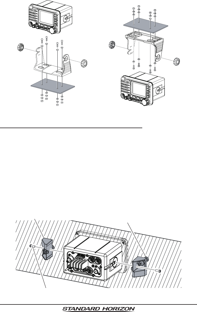
7.4 ELECTRICAL CONNECTIONS
CAUTION
Reverse polarity battery connections will damage the radio!
Connect the power cord and antenna to the radio. Antenna and Power Supply
connections are as follows:
1. Mount the antenna at least 3 feet (1 m) away from the radio. At the rear of
the radio, connect the antenna cable. The antenna cable must have a PL259
connector attached. RG-8/U coaxial cable must be used if the antenna is 25
feet (7.6 m) or more from the radio. RG58 cable can be used for distances
less than 25 feet (7.6 m).
2. Connect the red power wire to a 13.8 VDC ±20% power source. Connect
the black power wire to a negative ground.
3. If an optional remote extension speaker is to be used, refer to section 6.5
for connections.
4. It is advisable to have a Certied Marine Technician check the power output
and the standing wave ratio of the antenna after installation.
GPS Navigation Receiver
Optional Speaker
Optional Speaker
Fuse
Red
Power Source
Black
Voice
Antenna
Water proof
Deck Outlet
Optional SSM-70H
(RAM4) Remote MIC
Optional HAIL/PA Horn
Accessory Cables
AIS
Antenna
Optional SCU-31
GPS Antenna
Optional HAIL/PA Horn
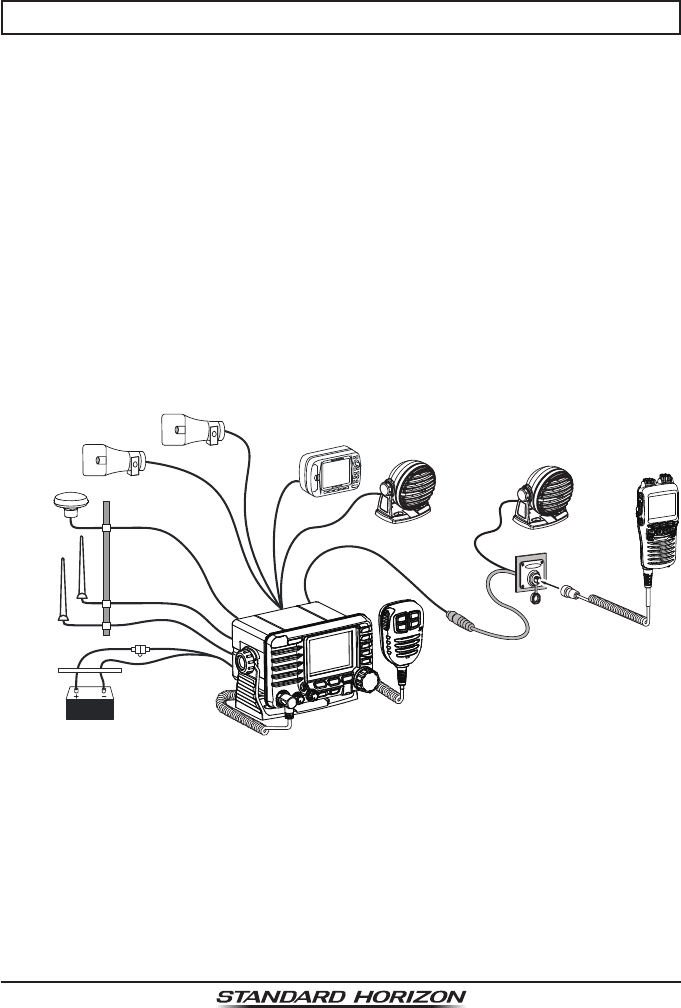
Ferrite Cores
To suppress RF interference that can cause abnormal operation of the transceiv-
er, attach the supplied two ferrite cores as shown in the next page: bigger one
to the accessory connection cable and the DC input cable together, and smaller
one to the PA speaker connection cable and the external speaker connection
cable together. Then snap the two halves of each ferrite core together.
Attach each ferrite core as close as possible to the transceiver body.
Finally, wind some plastic tape around each ferrite core, to prevent vibration
from causing the two halves to split apart.
Page 19
GX6000
As close as possible
Snap together
Snap together
Ferrite Core (Large)
Ferrite Core (Small)
{
{
DC Power Code
Speaker Code
Fuse Replacement
To take out the fuse from the fuse holder, hold both
ends of the fuse holder and pull the fuse holder
apart without bending the fuse holder. When you
replace the fuse, please conrm that the fuse is
tightly xed on the metal contact located inside
the fuse holder. If the metal contact holding the
fuse is loose, the fuse holder may heat up.
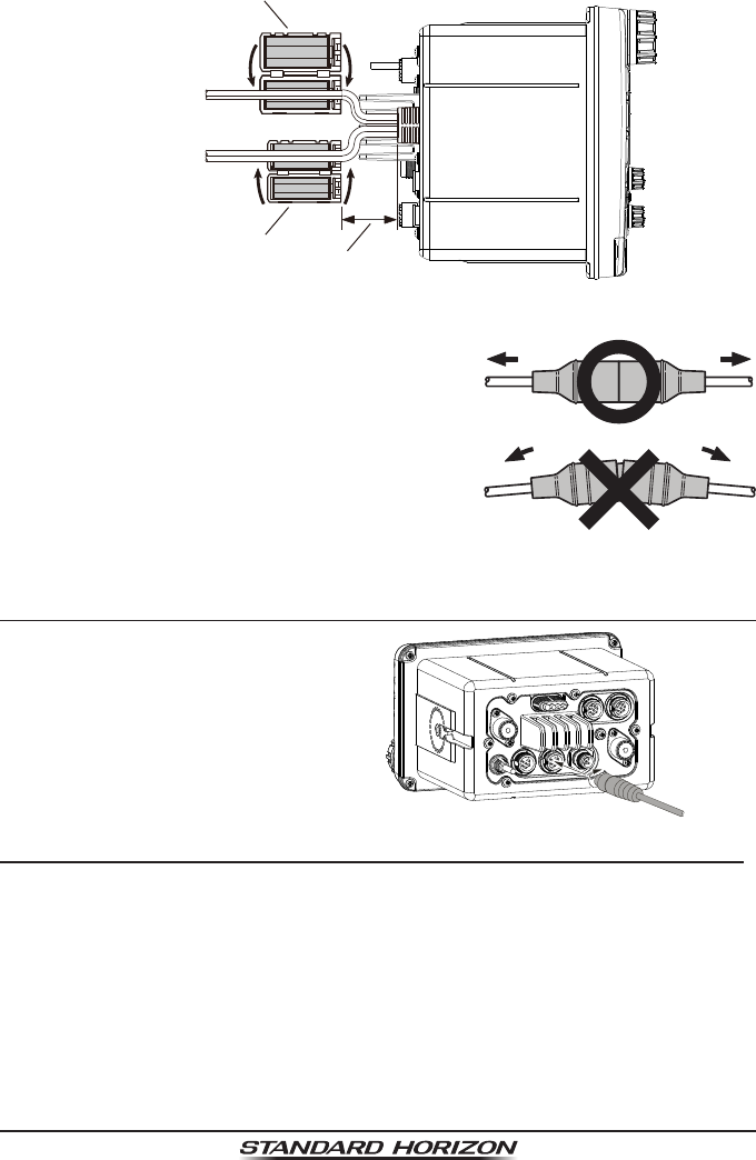
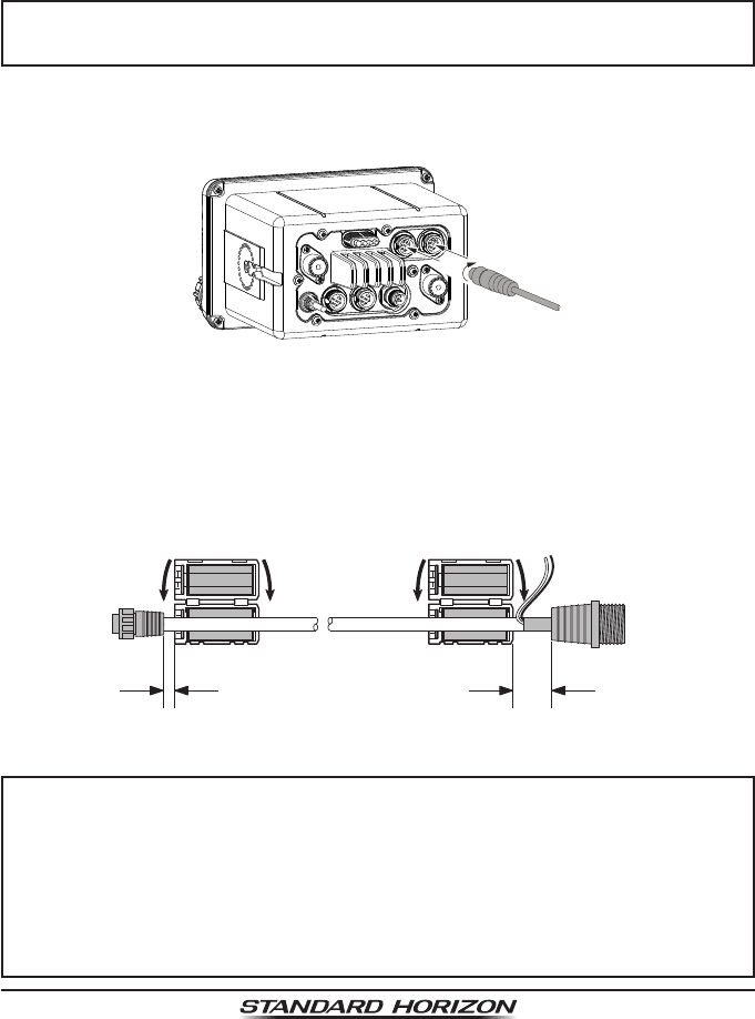
7.5 CONNECTION OF EXTERNAL DEVICES TO THE RADIO
7.5.1 Connecting the SCU-31 External GPS Antenna to the Radio
Connect the SCU-31 cable to the GPS
ANT (six pin) connector (White) on the
rear panel, then tighten the cable nut
(see illustration at the right).
7.5.2 Connecting the NMEA 0183/NMEA 0183-HS to the Radio
External GPS Connections (NMEA 0183 4800 baud or NMEA 0183-HS
38400 baud)
The GX6000 can select the NMEA baud rate between “4800 bps” and “38400
bps”. Refer to section “18.9 NMEA 0183 IN/OUT” for selection.
NMEA Input (GPS Information)
• GX6000 can read NMEA 0183 version 2.0 or higher, and NMEA 0183-HS
version 1.01 or higher.
• The NMEA 0183 input sentences are GLL, GGA, RMC, GNS, GSA, and
GSV (RMC sentence is recommended).
Page 20 GX6000
• If 4800 baud (default) is selected:
The Blue and Green wires of input are at 4800 baud.
• If 38400 baud is selected:
The Blue and Green wires of input are at 38400 baud.
NMEA Output (DSC and GPS information)
• The NMEA 0183 output sentences are DSC and DSE.
• If 4800 baud (default) is selected:
a. The Gray and Brown wires output DSC and DSE sentences.
b. The Yellow and White wires of output AIS VDM sentence at 38400 baud.
• If 38400 baud is selected:
a. The Gray and Brown wires of output are at 38400 baud and includes
both DSC (DSC, DSE) and AIS (VDM) sentences.
b. The Yellow and White wires always output AIS sentences at 38400 baud.
• GSA, GSV, GLL, GGA, and RMC sentences can be output in the GX6000
by setting through the GPS setup menu (refer to section “18.9 NMEA 0183
IN/OUT”).
For further information on interfacing/setting up your GPS, please contact the
manufacturer of the GPS receiver externally connected.
If you have further questions, please feel free to contact Product Support at:
Phone: (800) 767-2450
Email: marinetech@yaesu.com
7.5.3 Accessory Cables and NMEA 0183 Cables
The image and table below show the wires of the GX6000 and the connections
to optional devices such as an external GPS antenna, GPS chart plotter and
an AIS receiver.
CAUTION
Care must be taken not to touch any of the NMEA wires to positive 12
VDC or the radio may be damaged.
When connecting the GPS navigation receiver, strip off about 1 inch (2.5 cm)
of the specied wire’s insulation, then splice the ends together.
The GX6000 uses NMEA 0183/-HS protocol to share coordinates, DSC and
AIS information to and from a GPS chart plotter. The GX6000 transfers AIS
information to a GPS chart plotter at 38400 baud (sometimes called HS or High
Speed). GPS and DSC information is transferred between a GPS chart plotter
with multiple ports (minimum 2) at 4800 baud (default setting).
To connect to a GPS chart plotter which has one NMEA port, the GX6000 may
be setup to receive GPS coordinates, send DSC and AIS signals at 38400
baud. Refer to section “18.9 NMEA 0183 IN/OUT” for details.
Page 21
GX6000
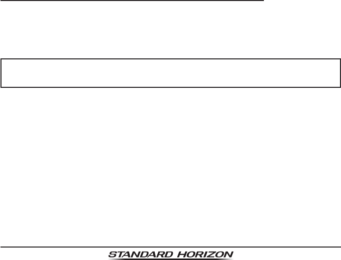
7.5.4 NMEA 0813/NMEA 0183-HS to Chart Plotter
4800 Baud Connections
GPS Chart PlotterPlotter ConnectionRadio Wires
No Connection
No Connection
NMEA IN (+)
NMEA-HS IN (+)
NMEA IN (−)
NMEA-HS IN (−)
Gray: NMEA OUT (+)
Brown: NMEA OUT (−)
Yellow: NMEA-HS OUT (+)
White: NMEA-HS OUT (−)
Blue: NMEA IN (+)
Green: NMEA IN (−)
External GPS Antenna
SCU-31 (optional)
Wire Color/Description Connection Examples
BLUE - NMEA GPS Input (+) No connection
GREEN - NMEA GPS Input (−) No connection
GRAY - NMEA DSC Output (+) NMEA (+) input of GPS*1
BROWN - NMEA DSC Output (−) NMEA (−) input of GPS*1
YELLOW - AIS Data Output (+) NMEA-HS (+) input of AIS receiver*2
WHITE - AIS Data Output (−) NMEA-HS (−) input of AIS receiver*2
*1: 4800 baud *2: 38400 baud
Note: Some GPS chart plotters have a single wire for NMEA signal ground. In such a case connect
the NMEA input (−) to the GPS chart plotter’s single NMEA signal ground wire, and leave the NMEA
output (−) open. In case the assignment of power supply and ground of a GPS chart plotter to be
used is different from that of the radio, connect the signal ground wire of the GPS chart plotter to
the ground terminal (GND) on the rear panel of the radio.
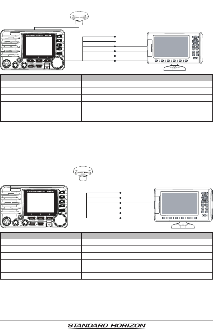
38400 Baud Connections
GPS Chart PlotterRadio Wires
Gray: NMEA OUT (+)
Brown: NMEA OUT (−)
Yellow: NMEA-HS OUT (+)
White: NMEA-HS OUT (−)
Blue: NMEA IN (+)
Green: NMEA IN (−)
Plotter Connection
No Connection
No Connection
NMEA IN (+)
No Connection
NMEA IN (−)
No Connection
External GPS Antenna
SCU-31 (optional)
Wire Color/Description Connection Examples
BLUE - NMEA GPS Input (+) No connection
GREEN - NMEA GPS Input (−) No connection
GRAY - NMEA DSC Output (+) NMEA (+) input of GPS*1
BROWN - NMEA DSC Output (−) NMEA (−) input of GPS*1
YELLOW - AIS Data Output (+) No connection*2
WHITE - AIS Data Output (−) No connection*2
*1:
The GPS chart plotter Com Port must be setup to 38400 baud (HS) to receive DSC and AIS sentences
from the GX6000 (Gray and Brown wires).
*2:
The GX6000 always outputs NMEA 0183-HS VDM sentence at 38400.
Note: Some GPS chart plotters have a single wire for NMEA signal ground. In such a case connect the NMEA
input (−) to the GPS chart plotter’s single NMEA signal ground wire, and leave the NMEA output (−) open. In case
the assignment of power supply and ground of a GPS chart plotter to be used is different from that of the radio,
connect the signal ground wire of the GPS chart plotter to the ground terminal (GND) on the rear panel of the radio.
Page 22 GX6000
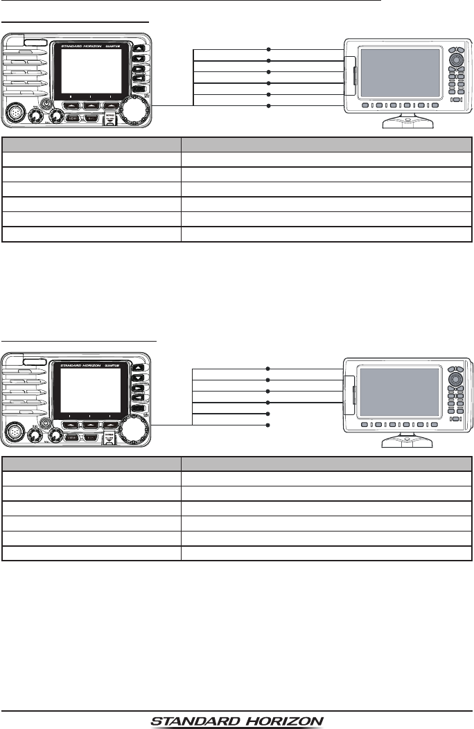
7.5.5 Connection to External GPS or Chart Plotter
4800 Baud Connections
GPS ReceiverRadio Wires
Gray: NMEA OUT (+)
Brown: NMEA OUT (−)
Yellow: NMEA-HS OUT (+)
White: NMEA-HS OUT (−)
Blue: NMEA IN (+)
Green: NMEA IN (−)
Plotter Connection
NMEA OUT (−)
NMEA OUT (+)
NMEA IN (+)
NMEA-HS IN (+)
NMEA IN (−)
NMEA-HS IN (−)
Wire Color/Description Connection Examples
BLUE - NMEA GPS Input (+) NMEA (+) output of GPS*1
GREEN - NMEA GPS Input (−) NMEA (−) output or common ground of GPS*1
GRAY - NMEA DSC Output (+) NMEA (+) input of GPS*1
BROWN - NMEA DSC Output (−) NMEA (−) input of GPS*1
YELLOW - AIS Data Output (+) NMEA-HS (+) input of AIS receiver*2
WHITE - AIS Data Output (−) NMEA-HS (−) input of AIS receiver*2
*1: 4800 baud *2: 38400 baud
Note: Some GPS chart plotters have a single wire for NMEA signal ground. In such a case connect
the NMEA input (−) to the GPS chart plotter’s single NMEA signal ground wire, and leave the NMEA
output (−) open. In case the assignment of power supply and ground of a GPS chart plotter to be
used is different from that of the radio, connect the signal ground wire of the GPS chart plotter to
the ground terminal (GND) on the rear panel of the radio.
38400 Baud Connections
GPS ReceiverRadio Wires
Gray: NMEA OUT (+)
Brown: NMEA OUT (−)
Yellow: NMEA-HS OUT (+)
White: NMEA-HS OUT (−)
Blue: NMEA IN (+)
Green: NMEA IN (−)
Plotter Connection
NMEA OUT (−)
NMEA OUT (+)
NMEA IN (+)
No Connection
NMEA IN (−)
No Connection
Wire Color/Description Connection Examples
BLUE - NMEA GPS Input (+) NMEA (+) output of GPS*1
GREEN - NMEA GPS Input (−) NMEA (−) output or common ground of GPS*1
GRAY - NMEA DSC Output (+) NMEA (+) input of GPS*1
BROWN - NMEA DSC Output (−) NMEA (−) input of GPS*1
YELLOW - AIS Data Output (+) No connection*2
WHITE - AIS Data Output (−) No connection*2
*1: The GPS chart plotter ComPort must be setup to 38400 baud (HS) to send GPS coordinates to
the GX6000 (Blue and Green wires) and to receive DSC and AIS sentences from the GX6000
(Gray and Brown wires).
*2: The GX6000 always outputs NMEA 0183-HS VDM sentence at 38400.
Note: Some GPS chart plotters have a single wire for NMEA signal ground. In such a case connect
the NMEA input (−) to the GPS chart plotter’s single NMEA signal ground wire, and leave the NMEA
output (−) open. In case the assignment of power supply and ground of a GPS chart plotter to be
used is different from that of the radio, connect the signal ground wire of the GPS chart plotter to
the ground terminal (GND) on the rear panel of the radio.
Page 23
GX6000
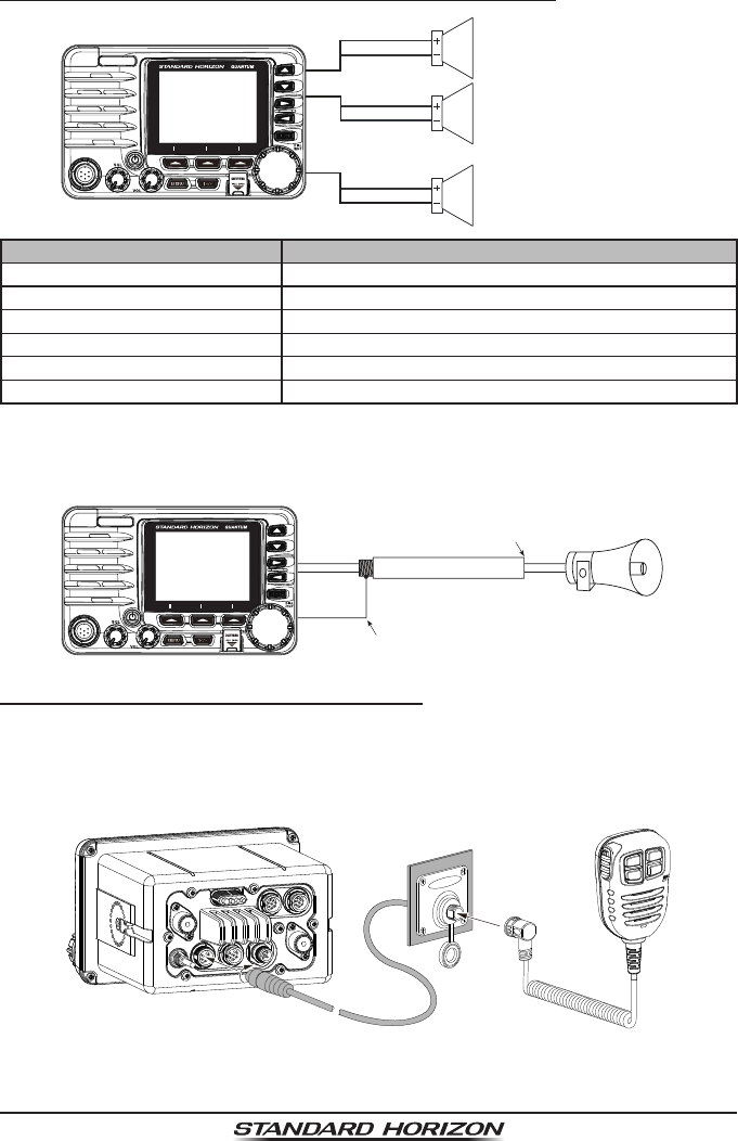
7.5.6 Connection to External PA/HAIL Speaker
PA
1 Speaker (horn)
External Speaker
BLUE
WHITE
GREEN
RED
PA
2 Speaker (horn)
YELLOW
ORANGE
Wire Color/Description Connection Examples
RED - External Speaker (+) Positive wire of external 4 Ohm External speaker
WHITE - External Speaker (−) Negative wire of external 4 Ohm External speaker
GREEN - PA1 Speaker (+) Positive wire of external 4 Ohm audio speaker (horn)
BLUE - PA1 Speaker (−) Negative wire of external 4 Ohm audio speaker (horn)
ORANGE - PA2 Speaker (+) Positive wire of external 4 Ohm audio speaker (horn)
YELLOW - PA2 Speaker (−) Negative wire of external 4 Ohm audio speaker (horn)
In some areas powerful AM broadcast stations may be heard when in listen-
back mode. In this case change the speaker wire to 2-conductor shielded audio
cable. See the illustration below for connections.
Red2 conductor shielded
Bare
Connect the shielded to GND Terminal of
the GX6000 rear panel.
Shield of cable is not
attached on PA Speaker end PA Speaker
7.5.7 Rear Microphone Installation
The GX6000 has an additional microphone connector on the rear panel
that provides the same function as that on the front panel. Connect the optional
MEK-4 (microphone extension kit) to the Rear MIC (six pin) connector on the
rear panel, then tighten the cable nut (see illustration at the below).
In addition, the GX6000 is capable of connecting hand microphone
to the connector on either the front or rear panels.
Page 24 GX6000
Optional SSM-70H (RAM4) Installation
The GX6000 is capable of using two SSM-70H (RAM4) Remote Station
Microphones to remotely control the Radio, AIS, DSC and PA/Fog functions. In
addition the GX6000 can operate as a full function intercom system between
the SSM-70H (RAM4) and the GX6000.
WARNING
Do not connect or remove the SSM-70H (RAM4) microphone while
the radio is powered on. This may result in equipment failure.
1. Connect the Routing Cable (supplied with the SSM-70H) to the RAM-1 or
RAM-2 (eight pin) connectors on the rear panel, then tighten the cable nut
(see illustration at the below).
2. Install the two ferrite core (supplied with the SSM-70H Remote Station
Microphone) to the routing cable or the CT-100 extension cable, then snap
its two halves together. These require to install near the connector by the
each side of a transceiver and a microphone of the cable.
3. Attach the ferrite cores as close as possible to the plugs, as shown below.
Routing Cable or
CT-100 Extension Cable
External Speaker
Connections
Ferrite Core
As close as possible
{
As close as possible
to GX6000 to SSM-70H
(RAM4)
Ferrite Core
NOTE
Caution!: Before cutting the cable, it must be disconnected from the rear
panel of the transceiver.
The routing cable can be cut and spliced, however care needs to be taken
when reconnecting the wires to ensure water integrity.
After cutting you will notice there are the following wires:
Yellow, White, Brown, Gray, Blue, Green, Red/White, Shield
The red/white and shield wires are wrapped in foil. Remove the foil, and
separate the red/white and shield wires.
Page 25
GX6000
4. Finally, wind some plastic tape
around each ferrite core, to
prevent vibration from causing
the two halves to split apart.
Wall
Gasket
Mounting Bracket
Routing Cable
Cap
Nut
External Speaker Connections
Ferrite Core
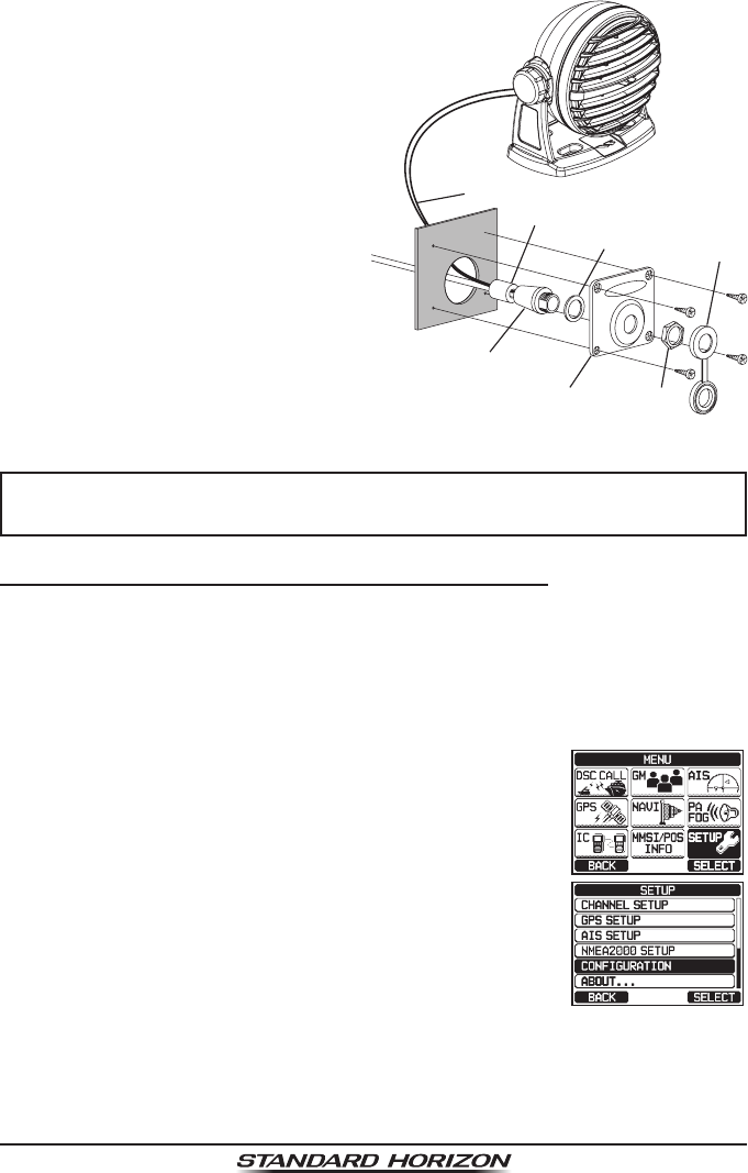
5. Referring to illustration right, make
a 1.2” (30 mm) hole in the wall,
then insert the extension cable
into this hole. Connect the gasket
and mount base to the extension
cable connector using the nut.
6. Drill the four screw holes (approx.
2 mm) on the wall, then install the
mounting base to the wall using
four screws.
7. Put the rubber cap on to the nut.
The installation is now complete.
WARNING
It is not recommended to plug or unplug the SSM-70H (RAM4) Remote
Station Microphone into the routing cable while the radio is powered on.
Connecting an External Speaker to the RAM4 Mic Cable
In noisy locations and MLS-300/MLS-310 optional external speaker may be
connected to the white speaker wires on the RAM4 routing cable. The RAM4
can drive the internal speaker or the external speaker one at a time. When
connecting an external speaker, follow the procedure below to turn off the
RAM4 audio and enable the external speaker wires on the RAM4 routing cable.
1. On the RAM4 mic, press the MENU key to display
“MENU”.
c
c
2. Rotate the DIAL/ENT knob to select “SETUP”, then
press the [SELECT] soft key.
3. Rotate the DIAL/ENT knob to select “CONFIGURA-
TION”, then press the [SELECT] soft key.
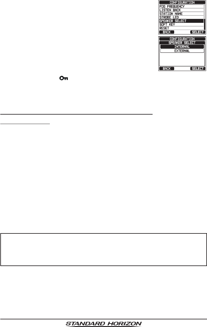
Page 26 GX6000
4. Rotate the DIAL/ENT knob to select “SPEAKER
SELECT”, then press the [SELECT] soft key.
5. Rotate the DIAL/ENT knob to select “INTERNAL” or
“EXTERNAL”, then press the [SELECT] soft key.
6. Press the CLEAR/ key to return to radio operation.
7.6 INITIAL SETUP REQUIRED WHEN TURNING ON THE
POWER FOR THE FIRST TIME
7.6.1 Maritime Mobile Service Identity (MMSI)
What is an MMSI?
An MMSI is a nine digit number used on marine transceivers capable of using
Digital Selective Calling (DSC) and Automatic Identication System (AIS) signal
transmission. This number is used like a telephone number to selectively call
other vessels.
THIS NUMBER MUST BE PROGRAMMED INTO THE RADIO TO OPERATE
DSC FUNCTIONS.
How can I obtain an MMSI assignment?
In the USA, visit the following websites to register:
http://www.boatus.com/mmsi/
https://www.seatow.com/tools-and-education/mmsi
http://wireless.fcc.gov/services/index.htm?job=licensing&id=ship_stations
In Canada, visit
http://www.ic.gc.ca/epic/site/smt-gst.nsf/en/sf01032e.html
WARNING
The MMSI can be inputted only once, please be careful not to input
the incorrect MMSI number. If you need to change the MMSI number
after it has been entered, the radio will have to be returned to Factory
Service. Refer to the section “21.2 FACTORY SERVICE”.
Page 27
GX6000
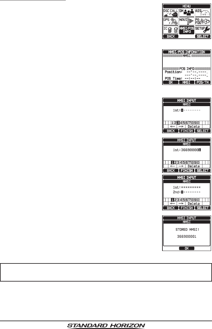
Programming the MMSI
1. Press the MENU key to display “MENU”.
2. Rotate the DIAL/ENT knob to select “MMSI/POS
INFO”, then press the [SELECT] soft key. (To cancel,
press the [BACK] soft key.)
To view your MMSI to ensure it is correct, perform
steps 1 to 2.
3. Press the [MMSI] soft key.
The [MMSI] soft key is displayed which has not yet
set the MMSI.
In the case of the GX6000 which has completed the
MMSI setting, you can only check the MMSI on this
screen.
*********
4. Rotate the DIAL/ENT knob to select the rst number
of your MMSI, then press the [SELECT] soft key to
step to the next number.
5. Repeat step 4 to set your MMSI number (9 digits).
6. If a mistake was made entering in the MMSI number,
rotate the DIAL/ENT knob to select “←” or “→”, press
the [SELECT] soft key until the wrong character is
selected, then perform step 4.
7. When nished programming the MMSI number, press
the [FINISH] soft key. The radio will ask you to input
the MMSI number again. Perform steps 4 through 6
above.
8. After the second number has been input, press the
[FINISH] soft key to store the MMSI.
9. Press the [OK] soft key to return to radio operation.
NOTE
To view your MMSI after programming to ensure it is correct, perform
steps 1 to 2. Look that the MMSI number shown on the display is correct.
Page 28 GX6000
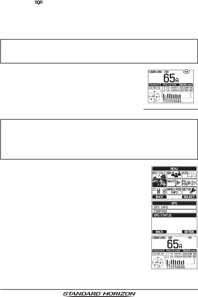
7.7 CHECKING GPS SIGNAL (GPS STATUS DISPLAY)
When the GX6000 receives the GPS signal from the optional SCU-31, a small
satellite icon “ ”* will appear on the display and your current location (latitude/
longitude) is shown on the display. (*When the GPS signal receiving from the
NMEA 2000 or NEMA-0183, a “2K” (NMEA 2000) icon or “I/O” (NMEA-0183)
icon will appear on the display.)
NOTE
If there is a problem with the NMEA connection between the radio and
the GPS, the GPS icon will blink continuously until the connection is
corrected.
The GX6000 has a GPS status display which shows the
satellites currently being received, along with a graphi-
cal (bar-graph) representation of the relative signal
strengths from the satellites.
(GPS StatuS diSPlay mode)
NOTE
For the GX6000 to properly show the GPS status page when an external
GPS antenna or a chart plotter is connected it must be setup to output
GSA and GSV NMEA 0183 sentences. When using the equipment of
NMEA 2000, it must be able to output PGN No.129540 (GNSS Sats
in View).
1. Press the MENU key to display “MENU”.
2. Rotate the DIAL/ENT knob to select “GPS”, then press
the [SELECT] soft key.
3. Rotate the DIAL/ENT knob to select “GPS STATUS”,
then press the [ENTER] soft key to display the GPS
status currently being received.
4. Press the CLEAR key to return to radio operation.
Page 29
GX6000
7.8 GPS CONFIGURATION
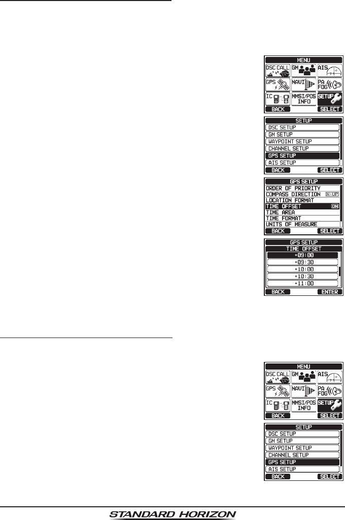
7.8.1 Changing the GPS Time
The GX6000 shows GPS satellite time or UTC (Universal Time Coordinated)
time in factory default. A time offset is needed to show the local time in your
area. The time offset must be changed in order for the radio to display the
current time in your area.
1. Press the MENU key to display “MENU”.
c
c
2. Rotate the DIAL/ENT knob to select “SETUP”, then
press the [SELECT] soft key.
3. Rotate the DIAL/ENT knob to select “GPS SETUP”,
then press the [SELECT] soft key.
4. Rotate the DIAL/ENT knob to select “TIME OFFSET”,
then press the [SELECT] soft key.
5. Rotate the DIAL/ENT knob to select time offset of
your location. See illustration above to nd your offset
time. If “00:00” is assigned, the time is the same as
UTC or GPS satellite time.
6. Press the [ENTER] soft key to store the time offset.
7. Press the CLEAR key to return to radio operation.
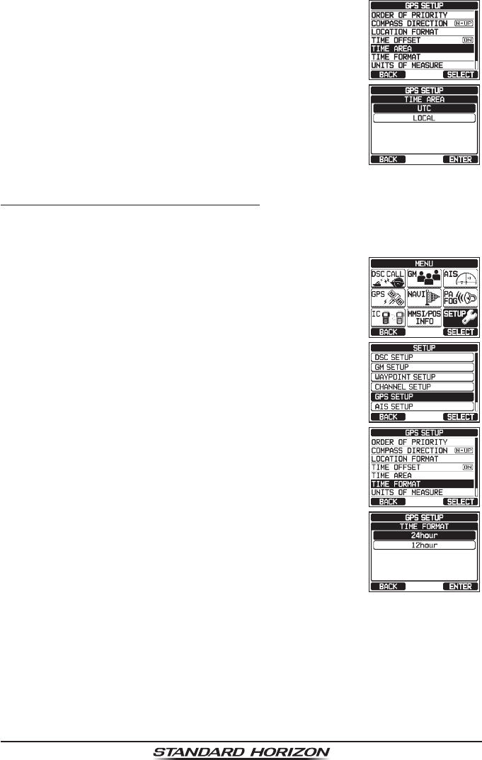
7.8.2 Changing the Time Area
This menu selection allows the radio to show UTC time or local time with offset.
1. Press the MENU key to display “MENU”.
c
c
2. Rotate the DIAL/ENT knob to select “SETUP”, then
press the [SELECT] soft key.
3. Rotate the DIAL/ENT knob to select “GPS SETUP”,
then press the [SELECT] soft key.
Page 30 GX6000
4. Rotate the DIAL/ENT knob to select “TIME AREA”,
then press the [SELECT] soft key.
5. Rotate the DIAL/ENT knob to select “UTC” or
“LOCAL”.
6. Press the [ENTER] soft key to store the selected
setting.
7. Press the CLEAR key to return to radio operation.
7.8.3 Changing the Time Format
This menu selection allows the radio to setup to show time in 12-hour or
24-hour format.
1. Press the MENU key to display “MENU”.
c
c
2. Rotate the DIAL/ENT knob to select “SETUP”, then
press the [SELECT] soft key.
3. Rotate the DIAL/ENT knob to select “GPS SETUP”,
then press the [SELECT] soft key.
4. Rotate the DIAL/ENT knob to select “TIME FORMAT”,
then press the [SELECT] soft key.
5. Rotate the DIAL/ENT knob to select “24hour” or
“12hour”.
6. Press the [ENTER] soft key to store the selected
setting.
7. Press the CLEAR key to return to radio operation.