Alcatel Canada 24T28A01D22C 7390 24 GHz Co-Pol RBS User Manual BS Manual pages 17 to 30
Alcatel Canada Inc 7390 24 GHz Co-Pol RBS BS Manual pages 17 to 30
Contents
- 1. BS Manual pages 1 to 16
- 2. BS Manual pages 17 to 30
- 3. BS Manual pages 31 to 40
- 4. BS Manual pages 41 to 45
- 5. BS Manual pages 46 to 50
- 6. BS Manual pages 51 to 55
- 7. BS Manual pages 56 to 60
- 8. BS Manual pages 61 to 70
- 9. BS Manual pages 71 to 76
- 10. BS Manual pages 77 to 125
- 11. BS Manual pages 126 to 182
- 12. BS Manual pages 183 to 190
- 13. BS Manual pages 191 to 228
- 14. BS Manual pages 229 to 246
- 15. BS Manual pages 247 to 276
- 16. BS Manual pages 277 to 280
- 17. BS Manual pages 281 to 284
- 18. BS Manual pages 285 to 302
BS Manual pages 17 to 30
3CC12424AAAA TQ BJA 01 Issue 01 - April 2001 - Draft 04 17/302
30
2 Equipment overview
2.1 Overview of the A7390 system
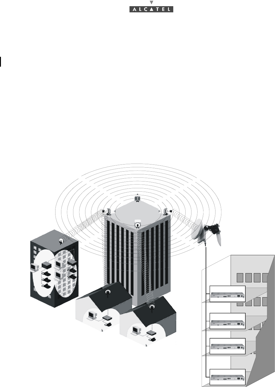
The Alcatel 7390 is a multi-service broadband wireless local loop system designed to provide telecom
services to small and medium-sized enterprises.
Broad band WLL (Wireless Local Loop) system, Alcatel 7390 allows operators to offer rapid provision -
to a large number of client sites - of a comprehensive range of telephone and data transmission
services.
For cellular phone network operators, Alcatel 7390 offers the possibility of linking base stations to
base station controllers. This makes Alcatel 7390 an economical transmission solution, for the
implementation or extension of high traffic density areas coverage.
For mixed network operators (fixed and mobile), Alcatel 7390 enables to connect, with the same
system, fixed professional end user as well as base stations of cellular telephony.
Figure 1 – A7390 System - Local point - multipoint service distribution -
SME
Independant profession
Independant profession
Compagny D
Compagny A
Compagny B
Compagny C
18/302 Issue 01 - April 2001 - Draft 04 3CC12424AAAA TQ BJA 01
30
2.2 Composition of the A7390 system
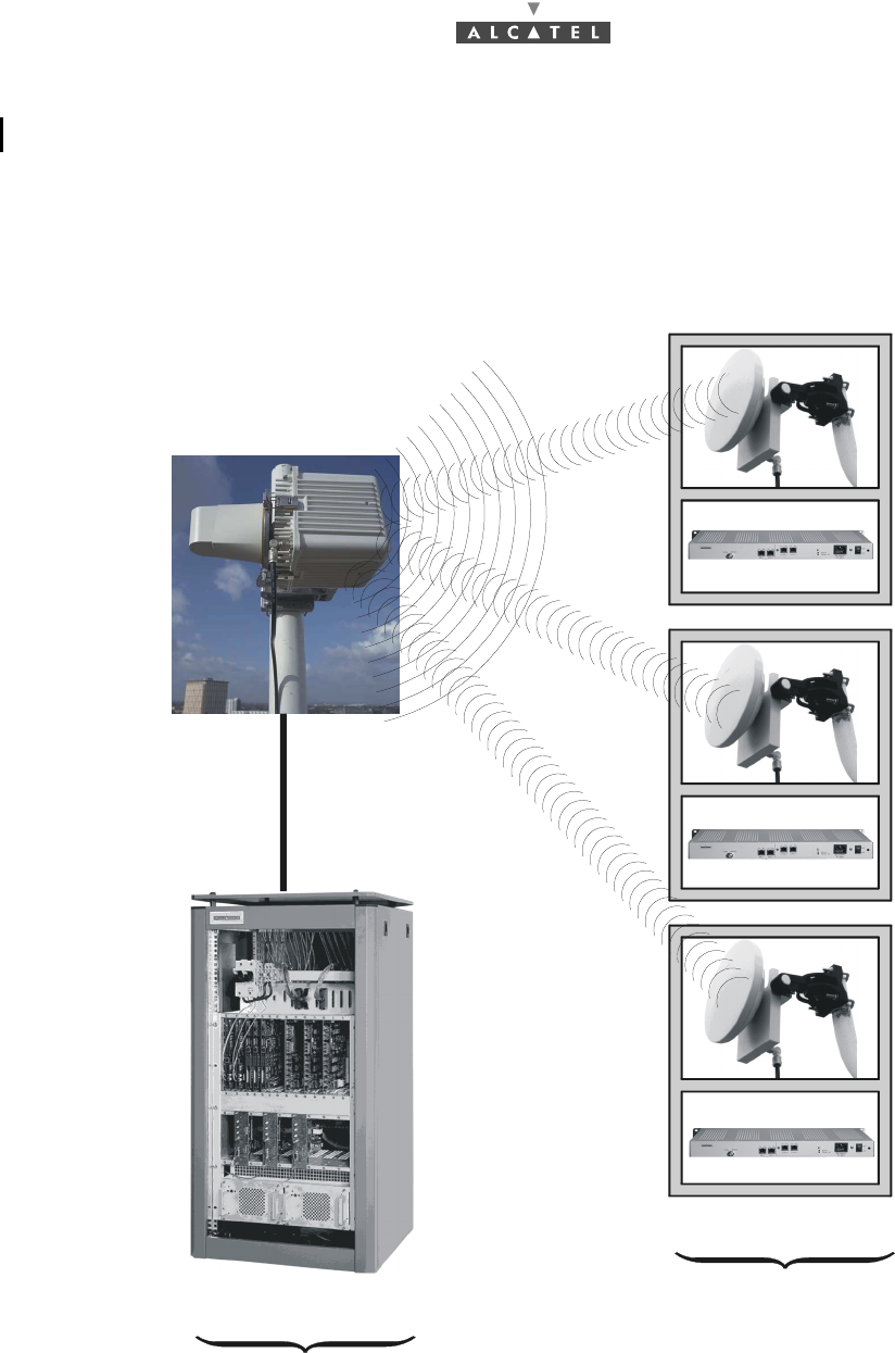
An A7390 network cell consists of the following:
–a common base station designated 7390BS;
–and several terminal stations distributed across the user sites, and designated 7390TS.
Figure 2 – Base Station and Terminal Stations
"Digital Base Station" DBS
"Terminal Stations"
"Radio Base Station" RBS
7390BS
nx7390TS
3CC12424AAAA TQ BJA 01 Issue 01 - April 2001 - Draft 04 19/302
30
2.3 A7390 system specifications
2.3.1 Frequency bands used
25 GHz frequency band:
–CEPT T/R 13-02E European recommendation 24.5 - 26.5 GHz
26 GHz frequency band:
–MPT (Japan) 25.25 - 27 GHz
–Korea 24.25 - 24.59 ; 25.73 - 26.07 GHz
28 GHz frequency band:
–27 GHz (LMCS - Canada) 27.35 - 28.35
–28 GHz (CEPT) 28.0 - 28.5, 29.0 - 29.5
–29 GHz (LMDS - USA) 27.5 - 28.35, 29.10 - 29.25
2.3.2 Radio transmission specifications (typical values)
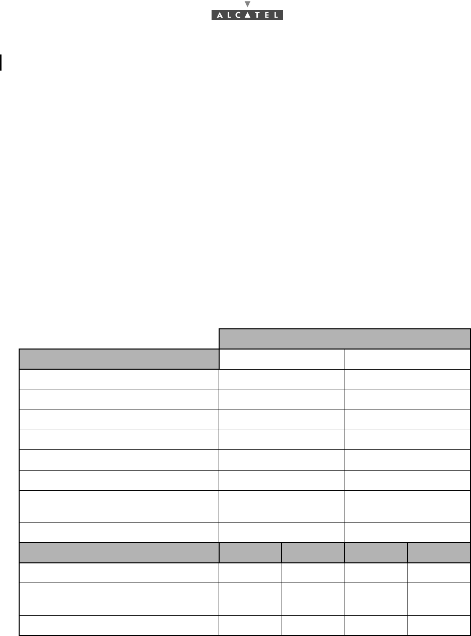
The following table gives the main radio characteristics of the A7390 wireless system.
A downstream (BS to TS) carrier is combined with up to four upstream (TS to BS) carriers.
Downstream
Channel bandwidth 14 MHz 28 MHz
Occupied bandwidth 13.63 MHz 27.25 MHz
Roll-off factor 35% 35%
Modulation QPSK QPSK
Gross bit rate 20.19 Mbit/s 40.37 Mbit/s
Inner Code Convol. 7/8 (k=7) Convol.7/8 (k=7)
Interleaving depth 12 depth 12
Outer Code Reed-Solomon
(204,188,8) Reed-Solomon
(204,188,8)
Bit rate before coding 16.19 Mbit/s 32.38 Mbit/s
Radio 25 GHz 28 GHz 25 GHz 28 GHz
RBS output power (antenna port) 17 dBm 17 dBm 17 dBm 17 dBm
Transmit antenna gain
(case of standard 90° antenna) 15 dB 15 dB 15 dB 15 dB
Receive antenna gain (with radome) 35 dB 34.5 dB 35 dB 34.5 dB
20/302 Issue 01 - April 2001 - Draft 04 3CC12424AAAA TQ BJA 01
30
2.3.3 Capacity
The system capacity depends on the traffic mix between data services (transported on ATM cells) and
leasedlines or telephony services (transported on TDM circuits).
It also depends on the channeling and the number of upstream channels.
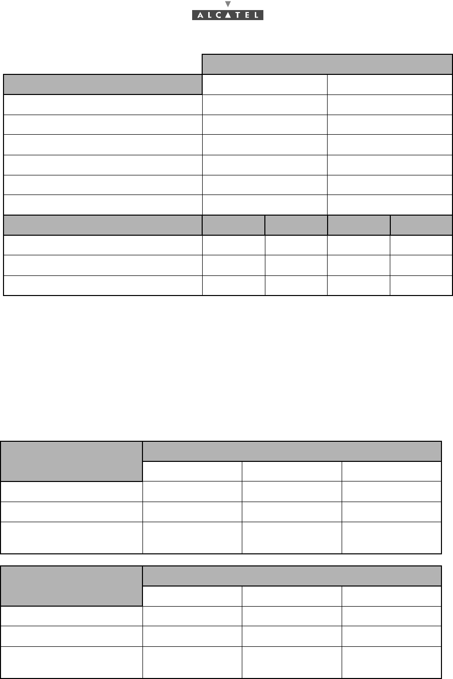
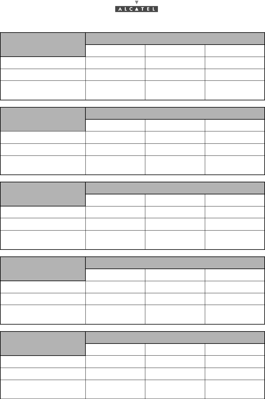
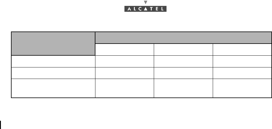
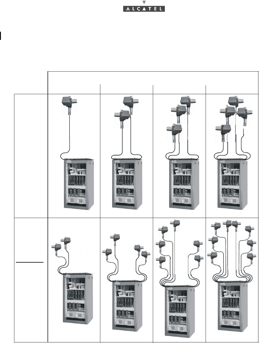
Figures are given in the following tables for three mix examples : minimum, medium and maximum
circuit capacity but any intermediate mix is possible.
Upstream
Channel bandwidth 3.5 MHz 7 MHz
Occupied bandwidth 3.36 MHz 6.72 MHz
Roll-off factor 25% 25%
Modulation D-QPSK D-QPSK
Gross bit rate 5.38 Mbit/s 10.75 Mbit/s
Outer Code Reed-Solomon (63,53,5) Reed-Solomon (63,53,5)
Bit rate before coding 4.19 Mbit/s 8.38 Mbit/s
Radio 25 GHz 28 GHz 25 GHz 28 GHz
TS output power (antenna port) 14 dBm 14 dBm 14 dBm 14 dBm
Transmit antenna gain 35 dB 34.5 dB 35 dB 34.5 dB
Receive antenna gain (with radome) 15 dB 15 dB 15 dB 15 dB
Downlink: 28 MHz Trafic MIX: circuit capacity
Uplink: 1 x 7 MHz Minimum Medium Maximum
Nb of circuits: 64 kbit/s 0 60 120
ATM uplink capacity (cells/s) 18.823 9.412 0
ATM downlink capacity (cells/
s) 75.512 66.530 57.399
Downlink : 28 MHz Trafic MIX: circuit capacity
Uplink : 2 x 7 MHz Minimum Medium Maximum
Nb of circuits: 64 kbit/s 0 120 240
ATM uplink capacity (cells/s) 37.647 18.823 0
ATM downlink capacity (cells/
s) 75.512 57.548 39.286
3CC12424AAAA TQ BJA 01 Issue 01 - April 2001 - Draft 04 21/302
30
Downlink : 28 MHz Trafic MIX: circuit capacity
Uplink : 3 x 7 MHz Minimum Medium Maximum
Nb of circuits: 64 kbit/s 0 180 360
ATM uplink capacity (cells/s) 56.471 28.235 0
ATM downlink capacity (cells/
s) 75.512 48.566 21.173
Downlink : 28 MHz Trafic MIX: circuit capacity
Uplink : 4 x 7 MHz Minimum Medium Maximum
Nb of circuits: 64 kbit/s 0 240 480
ATM uplink capacity (cells/s) 75.294 37.647 0
ATM downlink capacity (cells/
s) 75.512 39.585 3.084
Downlink: 14 MHz Trafic MIX: circuit capacity
Uplink: 1 x 3.5 MHz Minimum Medium Maximum
Nb of circuits: 64 kbit/s 0 30 60
ATM uplink capacity (cells/s) 9.412 4.706 0
ATM downlink capacity (cells/
s) 38.047 33.519 28.990
Downlink : 14 MHz Trafic MIX: circuit capacity
Uplink : 2 x 3.5 MHz Minimum Medium Maximum
Nb of circuits: 64 kbit/s 0 60 120
ATM uplink capacity (cells/s) 18.824 9.412 0
ATM downlink capacity (cells/
s) 38.047 28.990 19.934
Downlink : 14 MHz Trafic MIX: circuit capacity
Uplink : 3 x 3.5 MHz Minimum Medium Maximum
Nb of circuits: 64 kbit/s 0 90 180
ATM uplink capacity (cells/s) 28.235 14.118 0
ATM downlink capacity (cells/
s) 38.047 24.462 10.877
22/302 Issue 01 - April 2001 - Draft 04 3CC12424AAAA TQ BJA 01
30
2.4 Simplified description of the Base Station (7390BS)
The A7390 system Base Station (7390BS) consists of the following main elements:
–one or more (up to 4) external transceivers, comprising the radio and the antenna part and de-
signated "RBS" (Radio Base Station);
–one modem rack, including the power supply unit and interfaces; this is the "indoor" part and de-
signated DBS (Digital Base Station);
–a cable linking the RBS and the DBS ("RBS/DBS link");
–a network management and configuration station (7390LT), based on the use of a PC with appro-
priate software.
Downlink : 14 MHz Trafic MIX: circuit capacity
Uplink : 4 x 3.5 MHz Minimum Medium Maximum
Nb of circuits: 64 kbit/s 0 120 240
ATM uplink capacity (cells/s) 37.647 18.824 0
ATM downlink capacity (cells/
s) 38.047 19.934 1.821
3CC12424AAAA TQ BJA 01 Issue 01 - April 2001 - Draft 04 23/302
30
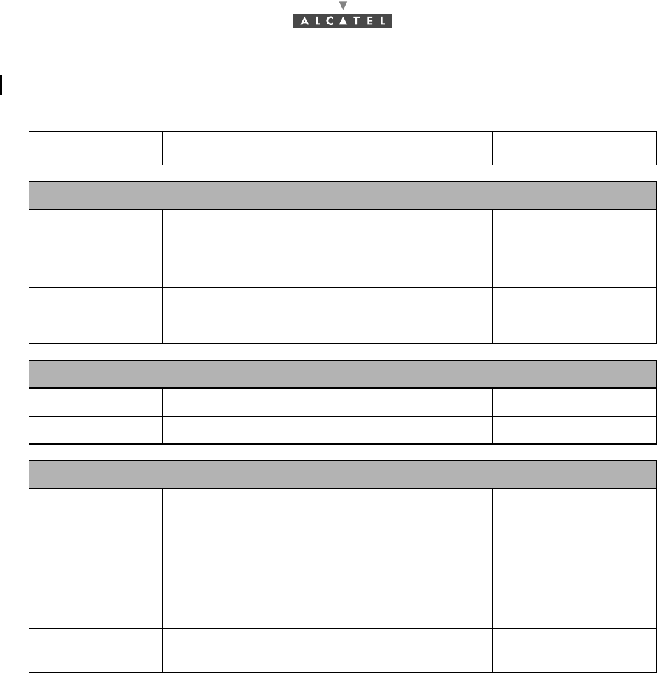
2.5 Examples of configuration of the Base Station (7390BS)
Figure 3 – Examples of configuration of the 7390BS
1234
Number of sectors
Configuration
1 + 0
Configuration
(redundancy)
1+1
24/302 Issue 01 - April 2001 - Draft 04 3CC12424AAAA TQ BJA 01
30
2.6 Technical specifications of the Base Station (7390BS)
2.6.1 RBS specifications
Designation Description Standards Observations
Mechanical specifications of the RBS assembly (antenna + pole mounting)
HxLxD 644(mm)x221(mm)x720(mm) -
D taken from axial tube
(diameter = 50 to
114mm) cf. diagram in
§ 3 Installation
Weight 15 kg - -
Physical interfaces: RBS/DBS indoor-outdoor cable
Connector type N/female - weatherproof
Medium 50Ω coaxial cable - -
Environmental specifications
RBS Classification -
ETS 300 019-2-4
IEC 721 3-4/
classes 4K2-4Z1-
4Z5-4Z7-4B1-
4C2-4S2-4M5
equipment for premi-
ses not sheltered from
the weather
Operating
temperature -33°C to + 55°C- -
Relative humidity
at 30°C100% - -
3CC12424AAAA TQ BJA 01 Issue 01 - April 2001 - Draft 04 25/302
30
2.6.2 DBS specifications
Note: Power supplies are floating level voltages; the ground cable can be connected to + 48V or - 48V
according to the country standards.
Designation Description Standards Observations
Mechanical specifications: Rack-mounted DBS assembly standard 19"
HxLxD 1250(mm)x600(mm)x600(mm)
ETS 300-119
cf. diagram in
§ 3 Installation
Weight <135 kg (including 85 kg for
empty rack) -
Mechanical specifications: DBS shelf without rack
HxLxD 844.55(mm)x482.6(mm)x540(mm) ETS 300-119
19-inch cf. diagram
in § 3 Installation
Weight < 50 kg -
Power supply and consumption
Primary voltage
range 36 V to 60 V
ETS 300-132
48 V rated voltage
Maximum con-
sumption 750 W including 8 RBS
Protection overvoltage, short-circuit
(40 A fuse), polarity inversion,
thermal protection
(ventilation failure)
-

26/302 Issue 01 - April 2001 - Draft 04 3CC12424AAAA TQ BJA 01
30
Designation Description Standards Observations
Physical interfaces: ATM network interface optical
Connector type SC/PC socket ITU-T I.432.2/§3.1 1300 nm
1 for each direction
Media Single-mode Fiber
(SMF; 9/125 µm) ITU-T G.652 1300 nm
1 for each direction
Environment Laser product Class 1 IEC 825
Bit rate
ITU-T I.432.2/§3.1
Nominal 155.520 Mbps
Timing ± 20 ppm Free run mode, i.e. under
synchronization source
fault conditions
Line coding NRZ
Jitter Refer to standard masks ITU-T G.958
Signalling UNI 4.0 ATM Forum
Af-sig-0061.000
Physical interfaces: E3 G703 (34 Mbps) (75 Ω)
Connector type
75Ω interface 1,6/5,6
Media
75Ω interface Coaxial cable ITU-T G.703/§8.3
Environment
Safety ETSI ETS 300-
418/§4.3, 4.4
EMC/EMI ETSI ETS 300-
418/§4.5
Bit rate ITU-T G.703/§8.1
Nominal 34.368 Mbps
Tolerance ± 20 ppm
Line coding HDB3
Jitter Refer to standard masks
Input tolerated jitter ITU-T G.823/§3
Output residual jitter ITU-T G.823/§2

3CC12424AAAA TQ BJA 01 Issue 01 - April 2001 - Draft 04 27/302
30
Designation Description Standards Observations
Physical interfaces: E1, TDM circuit interface (75/120 Ω)
Connector type
DBS Standard Sub-D/37 pins/fem. 8 connectors; 8 TDM
interfaces per connector
75Ω interface BNC or 1,6/5,6 1 for each direction
120Ω interface STP specific connector 1 for each direction
Media ITU-T G.703/§6.3
75Ω interface Coaxial cable 1 pair for each direction
120Ω interface STP 1 pair for each direction
Environment
Safety ETSI ETS 300-418/
§4.3, 4.4
EMC/EMI ETSI ETS 300-418/
§4.5
Bit rate
ITU-T G.703/§6.1
Nominal 2.048 Mbps Synchronous stream
Tolerance ± 50 ppm Under synchronization
source fault conditions
Line coding HDB3
Jitter Refer to standard masks
Input tolerated jitter ITU-T G.823/§3
Output residual jitter ITU-T G.823/§2
28/302 Issue 01 - April 2001 - Draft 04 3CC12424AAAA TQ BJA 01
30
Designation Description Standards Observations
Physical interfaces: T1 , TDM circuit interface (100 Ω)
Connector type
100Ω interface Sub-D 37 points
Media
100Ω interface Shielded twisted Pair ANSI T1.403
Bit rate
Nominal 1.544 Mbit/s ANSI T1.102
Tolerance ± 32 ppm ANSI T1.403
Line coding AMI or B8ZS Software configurable
Jitter Refer to standard masks
Input tolerated jitter ANSI T1.102
Output residual jitter ANSI T1.102
Environmental specifications
DBS Classification -
ETS 300 019-2-3 IEC
721 3-3/classes 3K5-
3Z2-3Z4-3B1-3C2-
3S2-3M1
-
Operating
temperature -5°C to +55°C- -
Relative humidity
at 30°C 93%
3CC12424AAAA TQ BJA 01 Issue 01 - April 2001 - Draft 04 29/302
30
2.6.3 Common characteristics of the RBS and DBS
2.7 Equipment power consumption
2.7.1 RBS
The typical power consumption of the RBS is 31 W (RBS cube) / 25 W (RBS flat).
2.7.2 DBS
Designation Description Standards Observations
Logistics
Transport Public transport: class 2.3 ETS 300 019-2-2 IEC
721-3-2 classes 2K4,
2B2, 2C2, 2S2, 2M3 -
Ambient temperature -40°C to+ 70°C- -
Relative humidity at
55°C95% - -
Storage Class 1.2
ETS 300 019-2-1 IEC
721-3-1 classes 1K4,
1Z2, 1Z3, 1Z5, 1B2,
1C2, 1S3, 1M2
storage premises
sheltered from the
weather, without air-
conditioning
Ambient temperature -40°C to + 70°C IEC 721-3-1/class 1K5 -
Relative humidity at
30°C
Condensation
100%
90 to 100 % --
DBS configuration type Typical power consumption
basic configuration (1 sector, 1+0) 130 W
per additional sector 100 W
1+1 redundancy (per sector) 100 W
ANT board (per board) 25 W
TNT board (per board) 30 W

30/302 Issue 01 - April 2001 - Draft 04 3CC12424AAAA TQ BJA 01
30
PAGE INTENTIONALLY LEFT BLANK