Alcatel Canada 24T28A01D22C 7390 24 GHz Co-Pol RBS User Manual BS Manual pages 71 to 76
Alcatel Canada Inc 7390 24 GHz Co-Pol RBS BS Manual pages 71 to 76
Contents
- 1. BS Manual pages 1 to 16
- 2. BS Manual pages 17 to 30
- 3. BS Manual pages 31 to 40
- 4. BS Manual pages 41 to 45
- 5. BS Manual pages 46 to 50
- 6. BS Manual pages 51 to 55
- 7. BS Manual pages 56 to 60
- 8. BS Manual pages 61 to 70
- 9. BS Manual pages 71 to 76
- 10. BS Manual pages 77 to 125
- 11. BS Manual pages 126 to 182
- 12. BS Manual pages 183 to 190
- 13. BS Manual pages 191 to 228
- 14. BS Manual pages 229 to 246
- 15. BS Manual pages 247 to 276
- 16. BS Manual pages 277 to 280
- 17. BS Manual pages 281 to 284
- 18. BS Manual pages 285 to 302
BS Manual pages 71 to 76
3CC12424AAAA TQ BJA 01 Issue 01 - April 2001 - Draft 04 71/302
76
3.5.4 Client access connections (ATM network interface)
3.5.4.1 Optical interface 155 Mbit/s
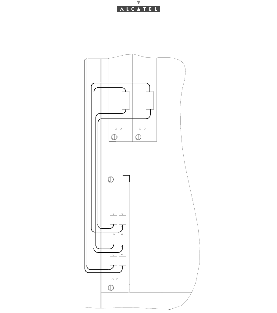
Figure 51 – Fiber optic cables connection
–use the fiber optic connection cables on the ANT and CPL board front panel.
–To avoid damaging the fiber optic cables:
•insert the jumpers in the direction indicated in Figure 53 – Fiber optic cables wiring,
•connect the fiber optic connection cable, fitted with its SC/PC connector, to the optical coupler
board by passing it through the top of the rack and along the cable run provided.
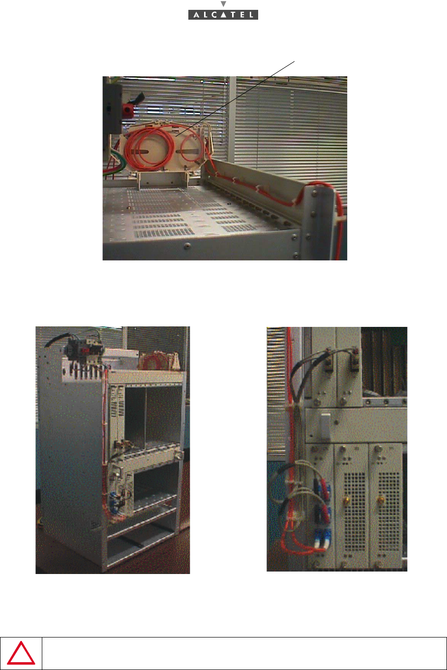
–Use a winding cassette when connecting one or more fiber optic cables of over 10 meters in length
(cf. Figure 52 – DBS fiber optic winding cassettes).
ANT 2ANT 1
IN
OUT OUT
IN
IN OUT
CPL
72/302 Issue 01 - April 2001 - Draft 04 3CC12424AAAA TQ BJA 01
76
Figure 52 – DBS fiber optic winding cassettes
Stages
1. According to the site configuration, prepare the connection cables and fit them with the required
connectors.
Figure 53 – Fiber optic cables wiring
2. Connect the fiber optic jumpers (see Figure 51 – Fiber optic cables connection and Figure 53 – Fiber
optic cables wiring) and the main cables.
DO NOT SET THE FIBER OPTIC IN FRONT OF THE VENTILATION PLUG-IN UNIT:
SET IT AS SHOWN IN FIGURE 50.
Winding cassettes
3CC12424AAAA TQ BJA 01 Issue 01 - April 2001 - Draft 04 73/302
76
3.5.4.2 Interface 34 Mbit/s
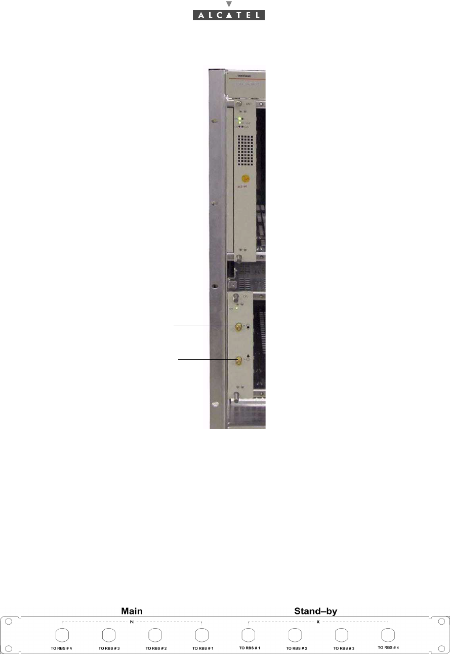
Figure 54 – 34 Mbit/s cables connection
3.5.5 RBS/DBS Connection
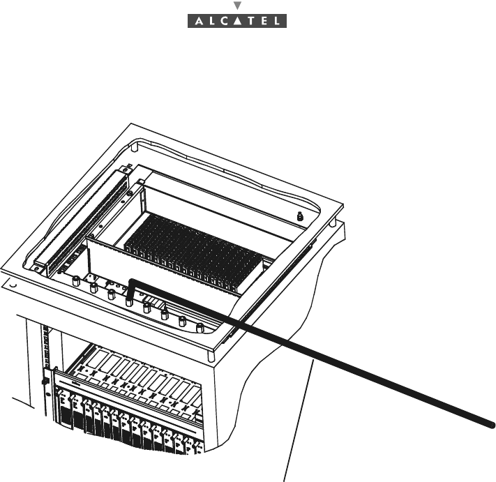
–Connect the RBS/DBS cable on the panel located at the top of the rack above the DBS chassis in
a standard rack.
–Each coaxial access is linked to an IBS board, via a coaxial cable included in the DBS chassis.
Note: Special care must be taken to check that each RBS is connected to the correct connector (to
each connector corresponds a specific sector).
Figure 55 – RBS connection panel
Input 34 Mbit/s
Output 34 Mbit/s
74/302 Issue 01 - April 2001 - Draft 04 3CC12424AAAA TQ BJA 01
76
Figure 56 – RBS Connection
Connection cable to one RBS
3CC12424AAAA TQ BJA 01 Issue 01 - April 2001 - Draft 04 75/302
76
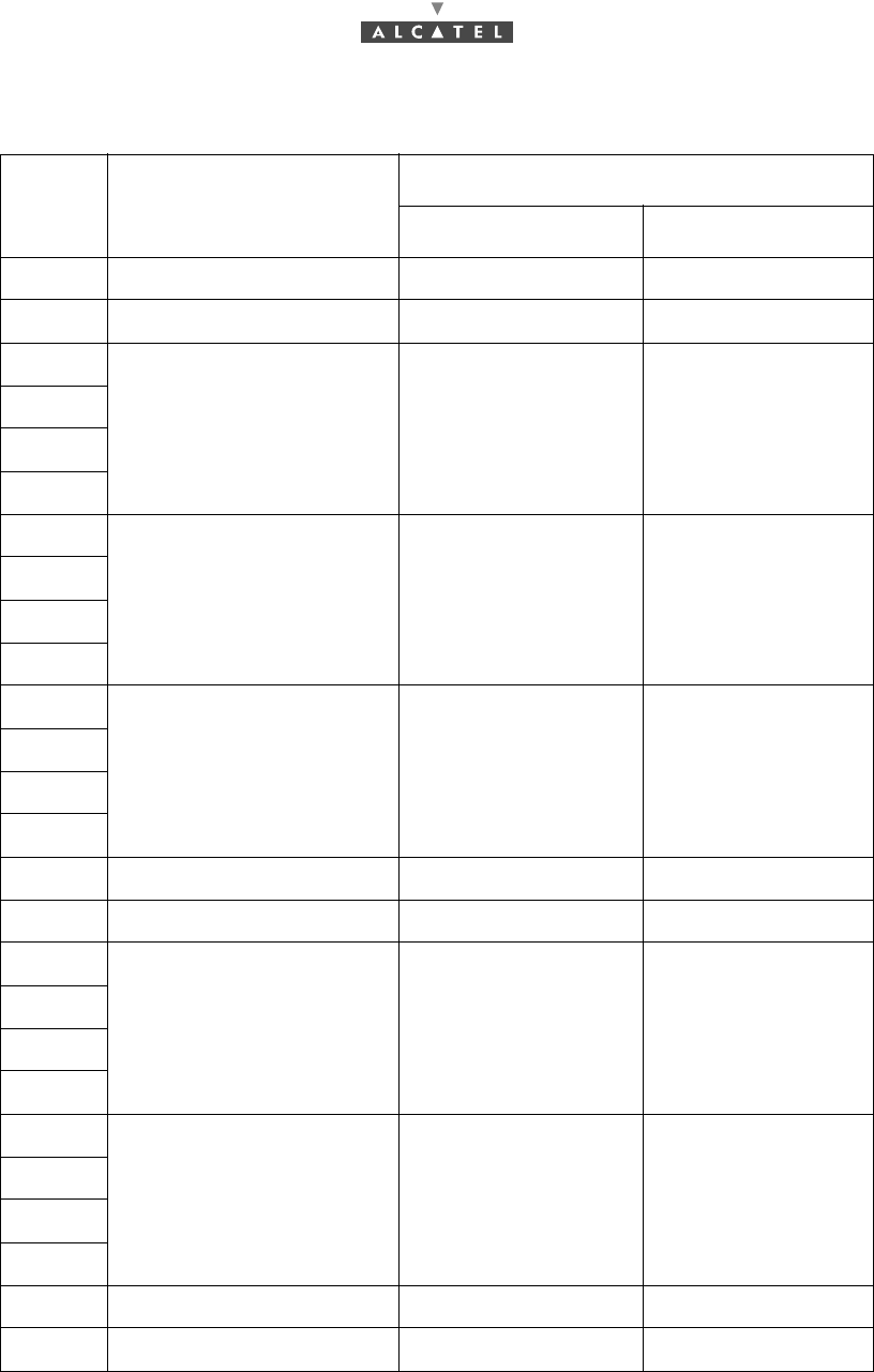
3.5.6 Place of the board into the rack
In the Configuration - redundancy (1+1) column, "x" means that checked boards are added to initially
installed boards (Configuration - initial (1+0) column).
Slots Type of the elements Configuration
main (1+0) redundancy (1+1)
1 ANT board x
2 ANT board x
3
TNT boards x
4
5
6
7
AMD boards x
8
9
10
11
AMD boards x
12
13
14
15 FAN x
16 CPL board x
17
IBS boards x
18
19
20
21
IBS boards x
22
23
24
25 Supply assembly PSU 1 x
26 Supply assembly PSU 2 x
76/302 Issue 01 - April 2001 - Draft 04 3CC12424AAAA TQ BJA 01
76
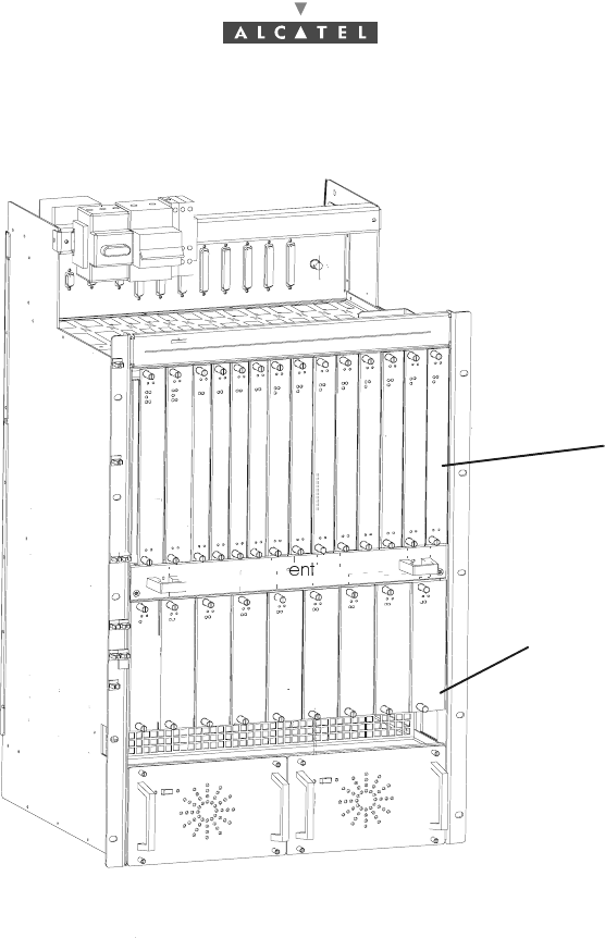
Figure 57 – Place of the boards into the DBS
3.5.7 End of the installation
Replace the (removable) top cover of the rack and secure it.
ANT 1
ANT 2
TNT 1
TNT 2
TNT 3
TNT 4
AMD 1
AMD 2
AMD 3
AMD 4
CPL
IBS 1
IBS 2
IBS 3
IBS 4
PSU 1 PSU 2
V
127
346
5109
813
11 14
12
15
17
16 19
18 20
25
23
2221 24
26
IBS 5
IBS 6
IBS 7
IBS 8
AMD 5
AMD 6
AMD 7
AMD 8
ID number
Slot number