Alcatel Canada 24T28A01D22C 7390 24 GHz Co-Pol RBS User Manual BS Manual pages 46 to 50
Alcatel Canada Inc 7390 24 GHz Co-Pol RBS BS Manual pages 46 to 50
Contents
- 1. BS Manual pages 1 to 16
- 2. BS Manual pages 17 to 30
- 3. BS Manual pages 31 to 40
- 4. BS Manual pages 41 to 45
- 5. BS Manual pages 46 to 50
- 6. BS Manual pages 51 to 55
- 7. BS Manual pages 56 to 60
- 8. BS Manual pages 61 to 70
- 9. BS Manual pages 71 to 76
- 10. BS Manual pages 77 to 125
- 11. BS Manual pages 126 to 182
- 12. BS Manual pages 183 to 190
- 13. BS Manual pages 191 to 228
- 14. BS Manual pages 229 to 246
- 15. BS Manual pages 247 to 276
- 16. BS Manual pages 277 to 280
- 17. BS Manual pages 281 to 284
- 18. BS Manual pages 285 to 302
BS Manual pages 46 to 50
46/302 Issue 01 - April 2001 - Draft 04 3CC12424AAAA TQ BJA 01
76
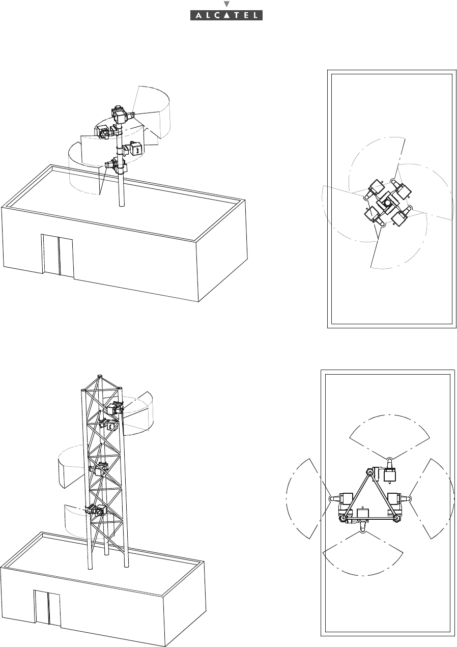
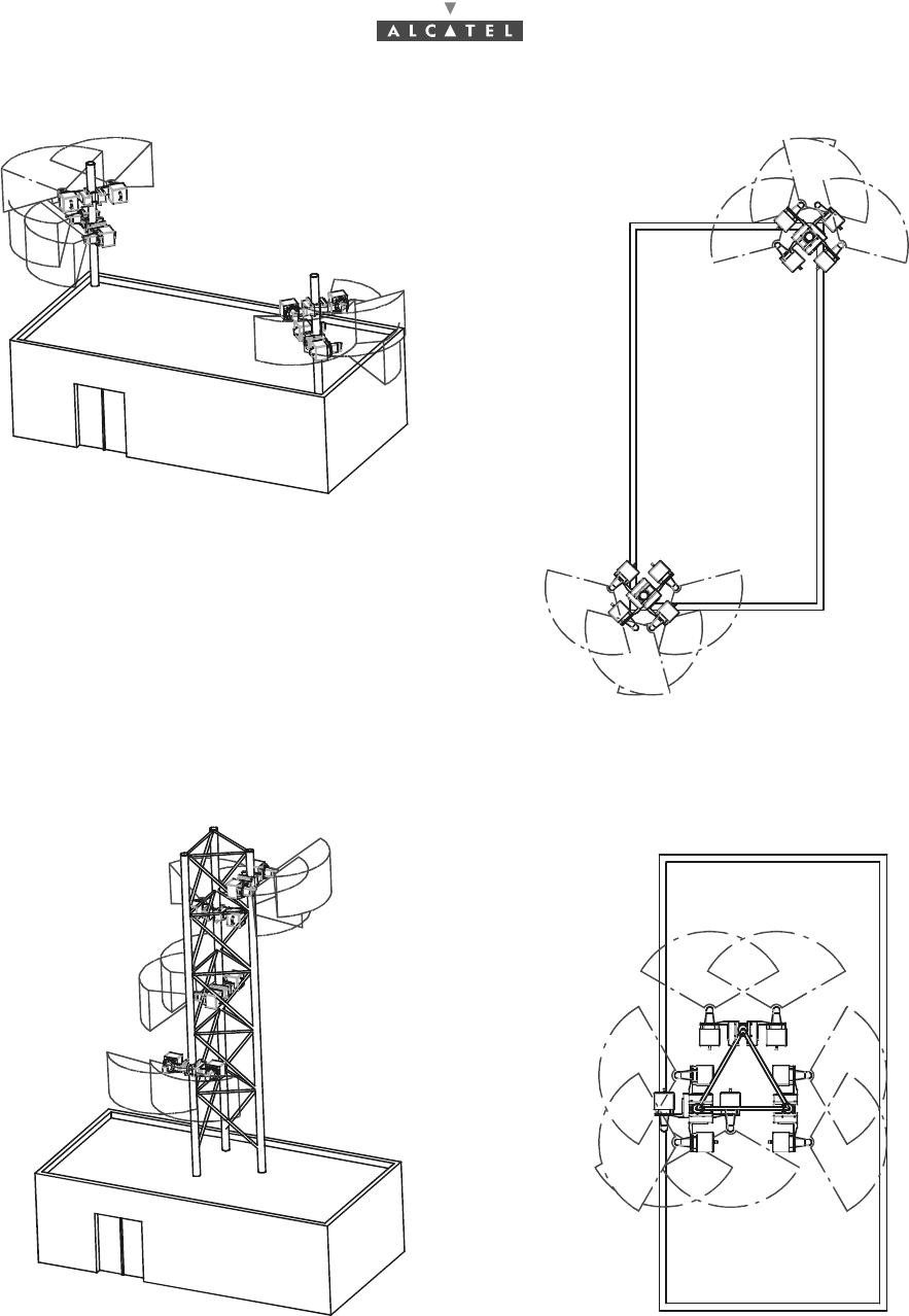
Figure 19 – Example of multi-RBS configuration: 4 RBS on the same mast (not advisable)
Figure 20 – Example of multi-RBS configuration: 4 RBS on the same pylon
Top view
Side view
Top view
Side view
3CC12424AAAA TQ BJA 01 Issue 01 - April 2001 - Draft 04 47/302
76
3.3.3.2 Configuration in 1+1 redundancy
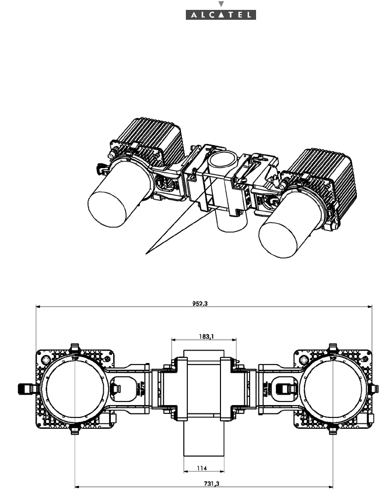
Implementation of RBS redundancy is achieved with the two pole-mounting fastening kit
(3CC11681Axxx).
CONFIGURATION IN 1+1 REDUNDANCY WITH RBS CUBE
Figure 21 – Coupling antennas in 1+1 redundancy: attachment kit and dimensions
Original
assembly
in 1+1
2 pole-mounting attachment kit
48/302 Issue 01 - April 2001 - Draft 04 3CC12424AAAA TQ BJA 01
76
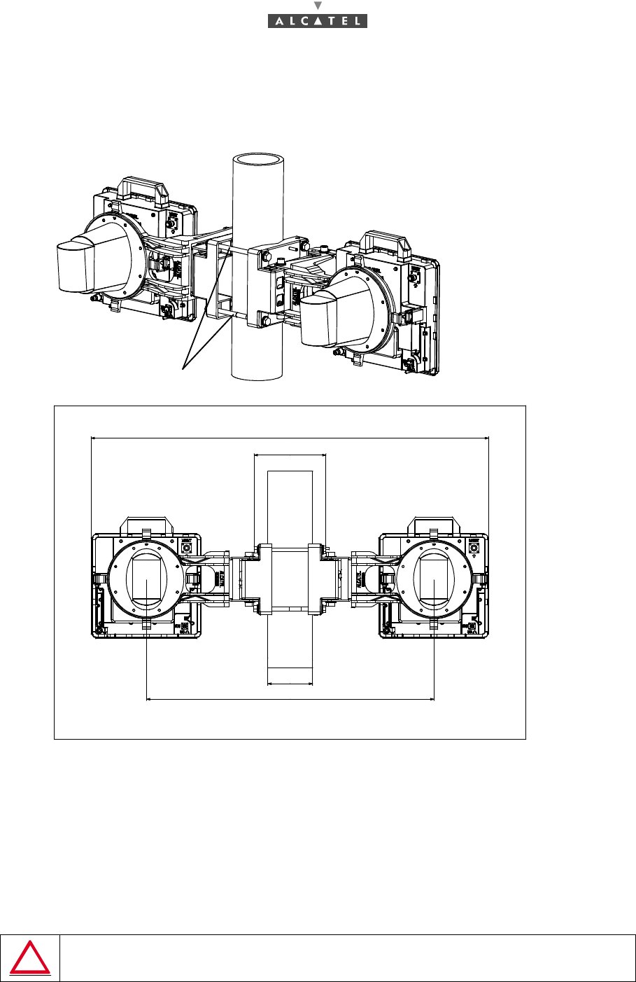
CONFIGURATION IN 1+1 REDUNDANCY WITH RBS FLAT
Figure 22 – Coupling antennas in 1+1 redundancy: attachment kit and dimensions
–Up to two adjacent sectors can be implemented on a same mast using two RBSs, each equip-
ped with a standard antenna (90°, 15 dBi).
–When 4 sectors are to be implemented, 2 different masts are required.
MAKE SURE THE RADIATION AREA OF EACH ANTENNA (90°) IS CLEAR OF ANY OBSTACLE.
CLEARANCE ANGLE TO ANTENNA AXIS: HORIZONTAL ± 60°, VERTICAL ± 20°
2 pole-mounting attachment kit
1011,3
114
183,1
731,3
Original
assembly
in 1+1
3CC12424AAAA TQ BJA 01 Issue 01 - April 2001 - Draft 04 49/302
76
3.3.3.3 Configuration for extension 1+1
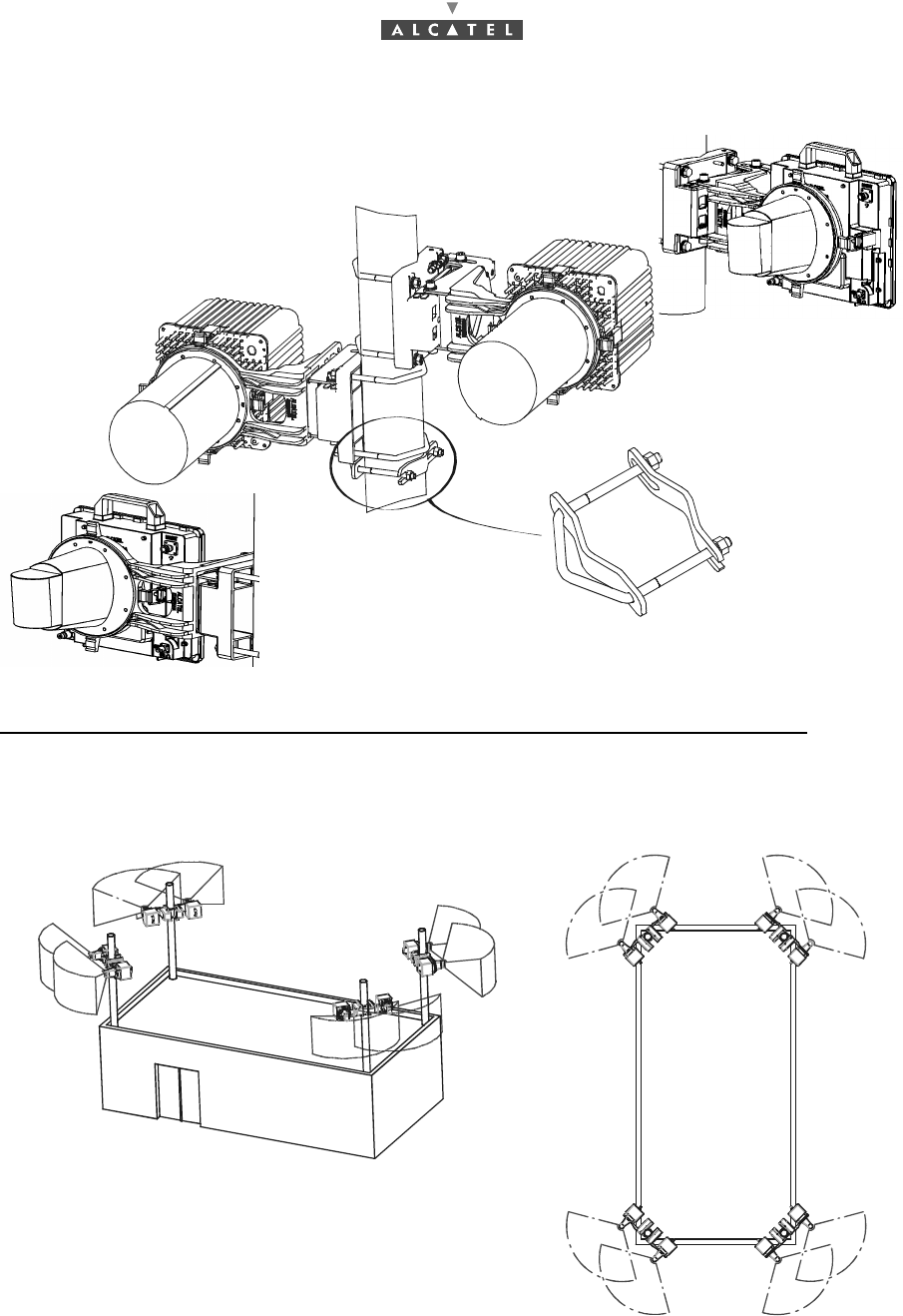
Multi-RBS configuration examples in the case of 4*2 RBSs to be installed (redundancy 1+1):
Figure 23 – Example of multi-RBS 1+1 configuration:
4 masters with 2 RBS per mast
Fixing tool for
antenna support
3CC11990Axxx
or
or
50/302 Issue 01 - April 2001 - Draft 04 3CC12424AAAA TQ BJA 01
76
Figure 24 – Example of multi-RBS (1+1) configuration:
2 masters with 4 RBS per mast
Figure 25 – Example of multi-RBS (1+1) configuration: 8 RBS on the same pylon