Alcatel Canada 24T28A01D22C 7390 24 GHz Co-Pol RBS User Manual BS Manual pages 41 to 45
Alcatel Canada Inc 7390 24 GHz Co-Pol RBS BS Manual pages 41 to 45
Contents
- 1. BS Manual pages 1 to 16
- 2. BS Manual pages 17 to 30
- 3. BS Manual pages 31 to 40
- 4. BS Manual pages 41 to 45
- 5. BS Manual pages 46 to 50
- 6. BS Manual pages 51 to 55
- 7. BS Manual pages 56 to 60
- 8. BS Manual pages 61 to 70
- 9. BS Manual pages 71 to 76
- 10. BS Manual pages 77 to 125
- 11. BS Manual pages 126 to 182
- 12. BS Manual pages 183 to 190
- 13. BS Manual pages 191 to 228
- 14. BS Manual pages 229 to 246
- 15. BS Manual pages 247 to 276
- 16. BS Manual pages 277 to 280
- 17. BS Manual pages 281 to 284
- 18. BS Manual pages 285 to 302
BS Manual pages 41 to 45
3CC12424AAAA TQ BJA 01 Issue 01 - April 2001 - Draft 04 41/302
76
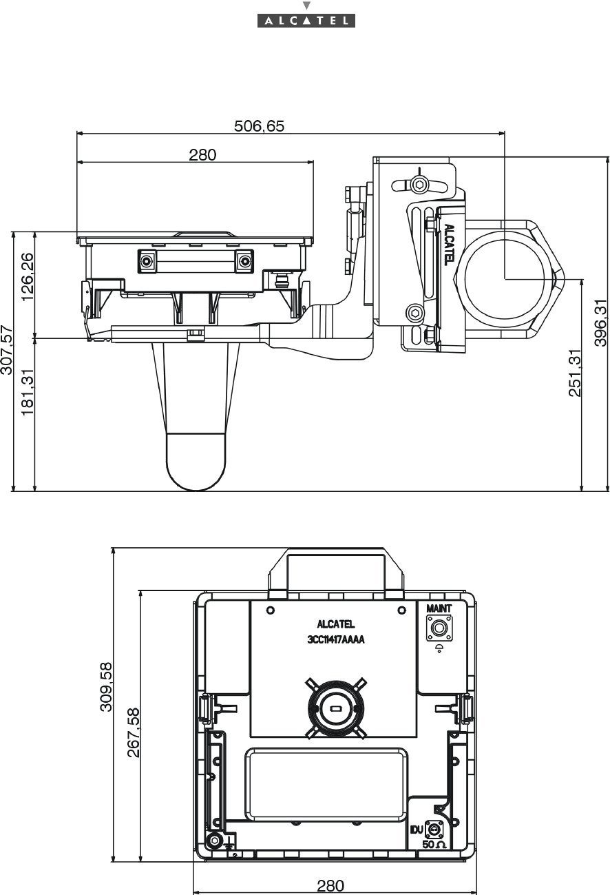
Figure 13 – Dimensions of the RBS flat unit
42/302 Issue 01 - April 2001 - Draft 04 3CC12424AAAA TQ BJA 01
76
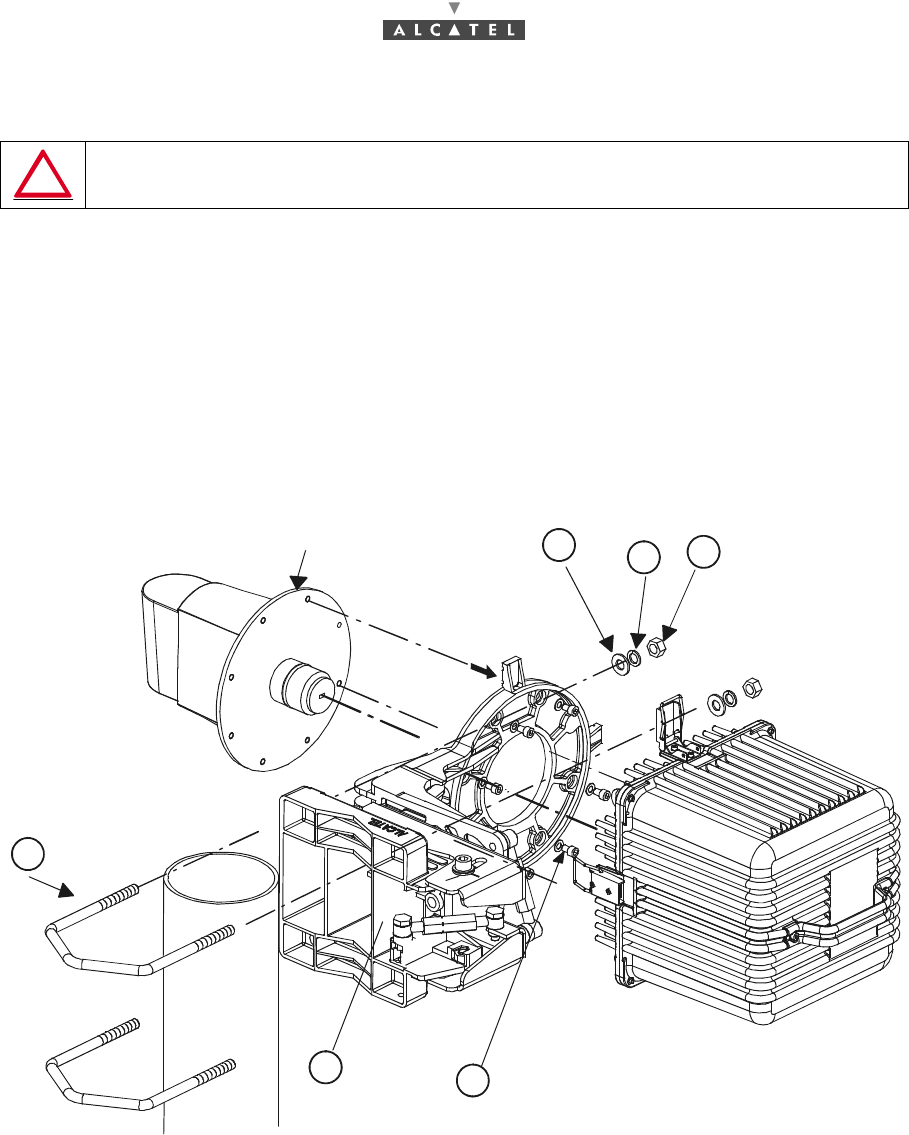
3.3.2 Installation and orientation of the mechanical system 9900UXI102
Considerations
–Installation can be carried out on an existing or newly installed tube or pole.
–The external diameter of the tube or pole is 114 mm in standard configuration.
–The mechanical assembly is supplied complete, mechanically assembled, with screw fastenings
kit and ground terminals.
Note: other tube diameters may be used depending on the loads to be supported: minimum diameter
76 mm and maximum 114; for this, please consult us.
Figure 14 – Installation of the pole mounting 9900UXI102 with RBS cube
VERTICALITY OF THE BEARING: ± 0.5 ° FOR THE POLE OR TUBE.
Brackets
Nut
Grower washer
Flat washer
"Top" marker
M6 x (7) screw
Casting
3CC12424AAAA TQ BJA 01 Issue 01 - April 2001 - Draft 04 43/302
76
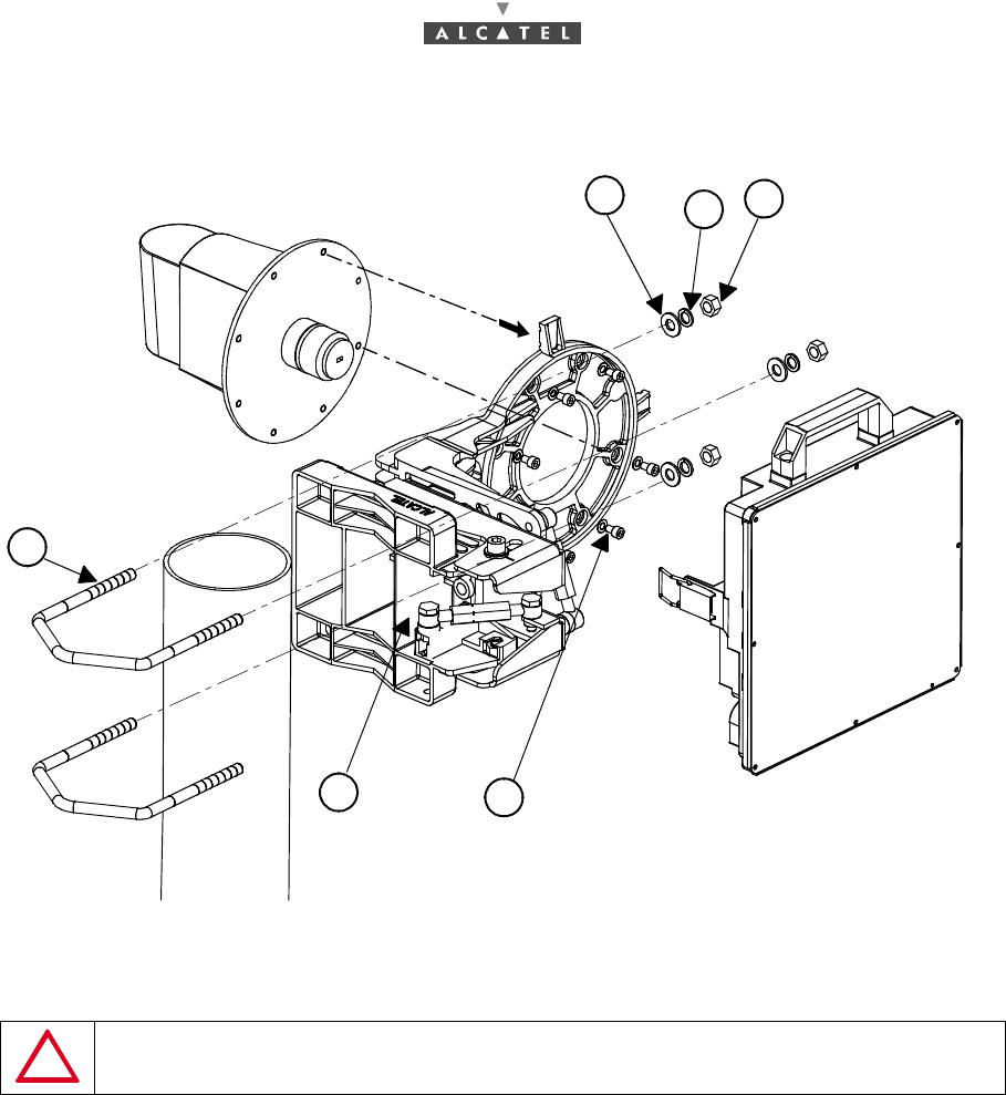
Figure 15 – Installation of the pole mounting 9900UXI102 with RBS flat
Note: the coarse horizontal alignement is done during the installation of the pole mounting.
IMPORTANT: YOU MUST DEFINE THE POSITION OF THE EQUIPMENT RESPECT TO
THE PIPE (RIGHT OR LEFT SIDE) BEFORE INSTALLING.
Nut
Grower washer
Flat washer
3
4
5
1
M6 x (7) screw
Casting
2
Brackets
6
44/302 Issue 01 - April 2001 - Draft 04 3CC12424AAAA TQ BJA 01
76
3.3.3 Installation rules for multi-RBS configurations
3.3.3.1 Main configuration (1+0)
For installation configurations containing several RBSs, imperatively apply the following rules to ensure
efficient radio transmissions:
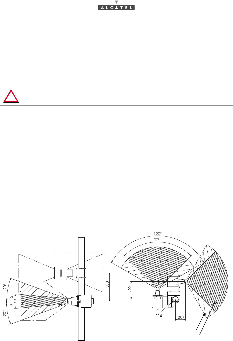
–Position the antenna to ensure best clearance; installation as near as possible to the corners of
the building or pylon is therefore strongly recommended. To avoid interference with the building
the antenna should not be too low: vertical clearance must be a view angle of at least ± 20° from
the antenna axis.
–For an installation involving initially less than 4 RBSs, select the location of the first RBSs leaving
space for other RBSs that may be added later in the event of extension to the installation.
–Several configurations are possible depending on the site and the number of radios; the installa-
tion should be the best compromise possible between: number of masts/radio performance. If the
different configurations possible - in the case of four radios to be installed on a building - are con-
sidered, the configuration giving the best compromise corresponds to figure 16, where 2 masts
have been installed with 2 RBSs per mast.
–However, it is allowable to install up to 4 RBS, equipped with the standard 90°/15 dBi antenna, on
the same mast (90° angle between each sector, see Figure 19 – Example of multi-RBS configu-
ration: 4 RBS on the same mast (not advisable)). This configuration can’t be upgraded to the 1+1
configuration. We strongly recommend to use 2 different tubes to allow 1+1 extension.
–In the case of use of several RBSs equipped with standard antennas on the same mast, the ins-
tallation restrictions are as follows:
•the lowest radio must avoid the highest point of the building (obey the 20° minimum clearance
angle specified above),
•the radios must be stacked at the same distance from each other, the minimum distance
between two consecutive antenna axes being 0.5 m (see Figure 16 – Clearances for adjacent
sectors).
Figure 16 – Clearances for adjacent sectors
THE 90° ANTENNA COVERAGE OF EACH ANTENNA MUST BE CLEAR OF OBSTACLES.
FROM ANTENNA AXIS : HORIZONTAL CLEARANCE : ± 60°, VERTICAL CLEARANCE ± 20°
¡
Clearances
Antenna Main Lobe
Dimensions are in millimeters
3CC12424AAAA TQ BJA 01 Issue 01 - April 2001 - Draft 04 45/302
76
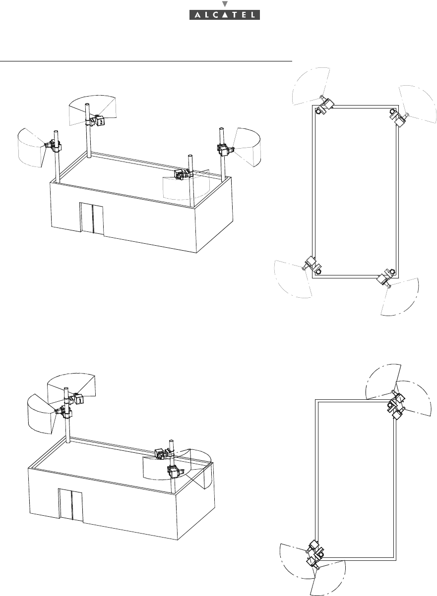
Multi-RBS configuration examples in the case of 4 RBS installation:
Figure 17 – Example of multi-RBS configuration: 4 masts with 1 RBS per mast
Figure 18 – Example of multi-RBS configuration: 2 masts with 2 RBS per mast (recommended)
Side view
Top view
Top view
Side view