Alcatel Canada 24T28A01D22C 7390 24 GHz Co-Pol RBS User Manual BS Manual pages 51 to 55
Alcatel Canada Inc 7390 24 GHz Co-Pol RBS BS Manual pages 51 to 55
Contents
- 1. BS Manual pages 1 to 16
- 2. BS Manual pages 17 to 30
- 3. BS Manual pages 31 to 40
- 4. BS Manual pages 41 to 45
- 5. BS Manual pages 46 to 50
- 6. BS Manual pages 51 to 55
- 7. BS Manual pages 56 to 60
- 8. BS Manual pages 61 to 70
- 9. BS Manual pages 71 to 76
- 10. BS Manual pages 77 to 125
- 11. BS Manual pages 126 to 182
- 12. BS Manual pages 183 to 190
- 13. BS Manual pages 191 to 228
- 14. BS Manual pages 229 to 246
- 15. BS Manual pages 247 to 276
- 16. BS Manual pages 277 to 280
- 17. BS Manual pages 281 to 284
- 18. BS Manual pages 285 to 302
BS Manual pages 51 to 55
3CC12424AAAA TQ BJA 01 Issue 01 - April 2001 - Draft 04 51/302
76
3.3.4 Installation of the RBS antenna on the pole mounting
Considerations
–The antenna must be installed before the RBS unit.
–The form of the sectored antennas may vary. Always refer to the "TOP" marking on the antenna
when installing on the pole mounting.
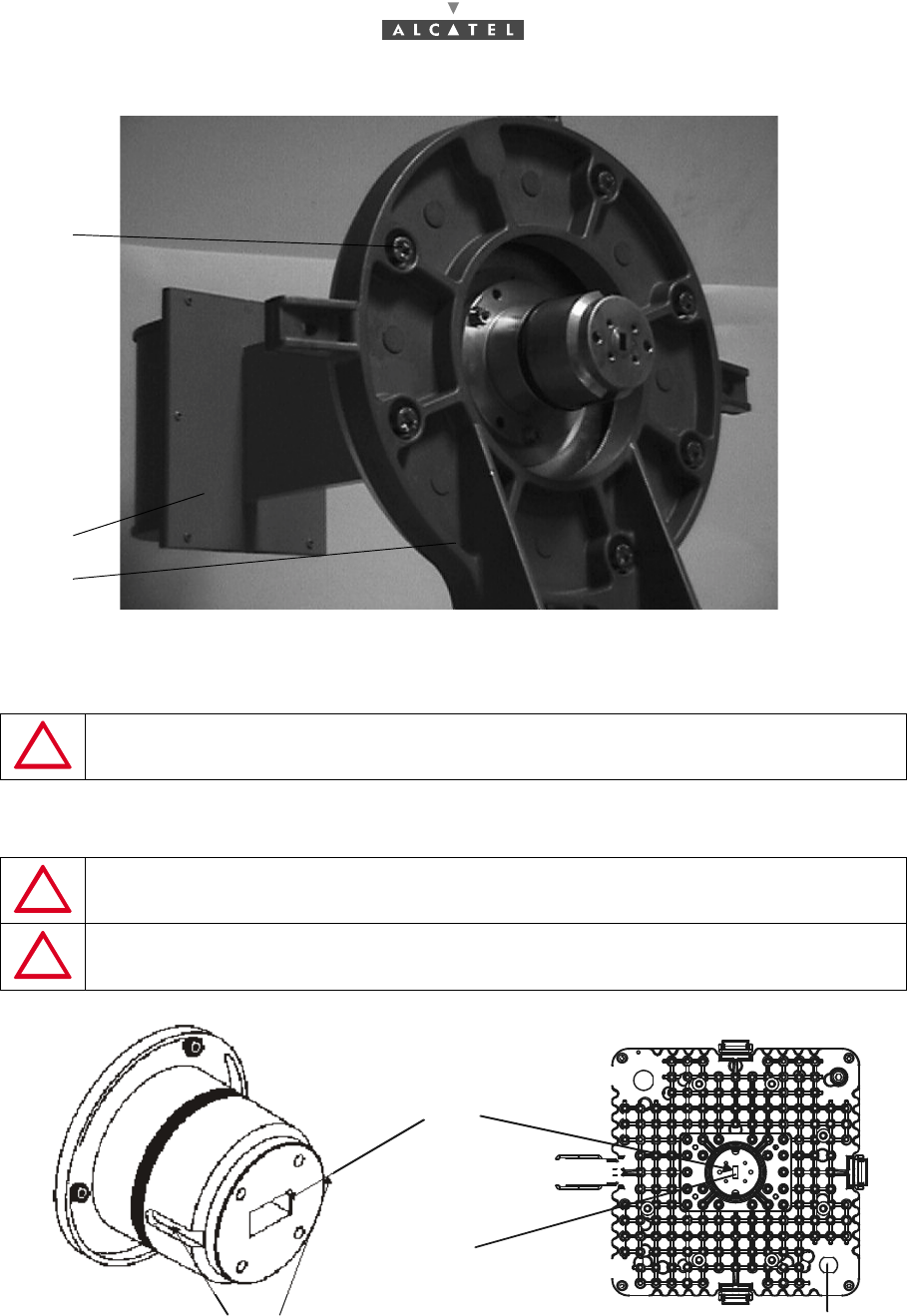
Storage (Figure 27 – Installing the RBS unit antenna)
1. Position the RBS antenna against the pole mounting support (ref. 2), and install it at the opposite
side of the RBS unit.
2. Secure the RBS antenna using seven M6 x 25 screws (ref. 3) and onduflex washers.
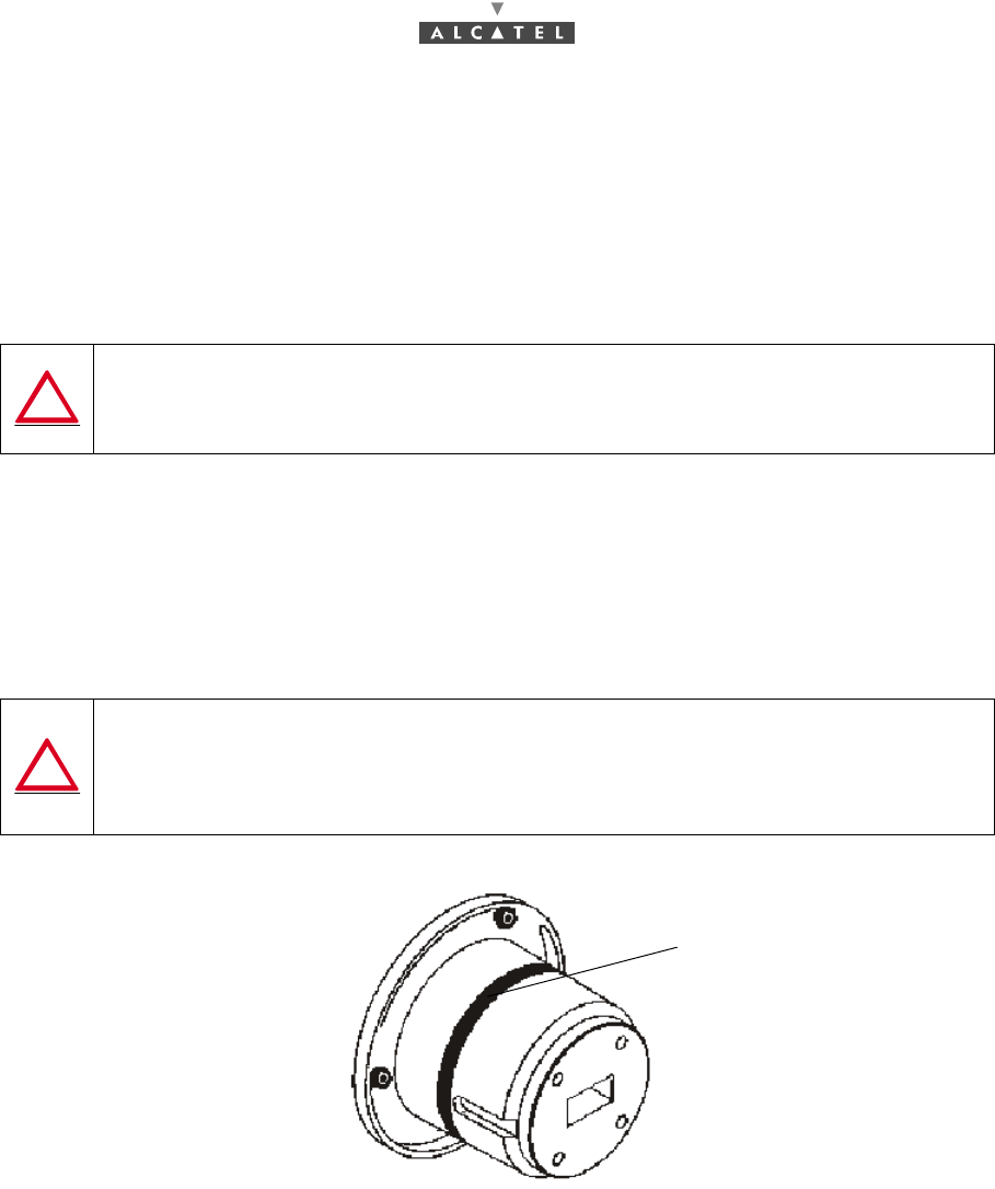
Figure 26 – Antenna nose
WHATEVER THE TYPE OF ANTENNA, WHETHER FOR VERTICAL OR
HORIZONTAL POLARIZATION, ALWAYS POSITION THE ANTENNA WITH THE "TOP"
MARKING UPPERMOST. THE ORIENTATION OF THE ACCESS GUIDE
DOES NOT DEFINE THE POLARIZATION.
TAKE CARE NOT TO DAMAGE THE O-RING SEAL ON THE NOSE OF THE
ANTENNA CONNECTION: SEE Figure 26 – Antenna nose.
IF THE RBSs ARE NOT TO BE MOUNTED IMMEDIATELY AFTER THE
MOUNTING OF THE ANTENNA, PROTECT THE CONNECTION NOSE
(FROM WATER, DIRT AND IMPACT).
O-ring seal
52/302 Issue 01 - April 2001 - Draft 04 3CC12424AAAA TQ BJA 01
76
Figure 27 – Installing the RBS unit antenna
3.3.5 Installation of the RBS Unit
Stages
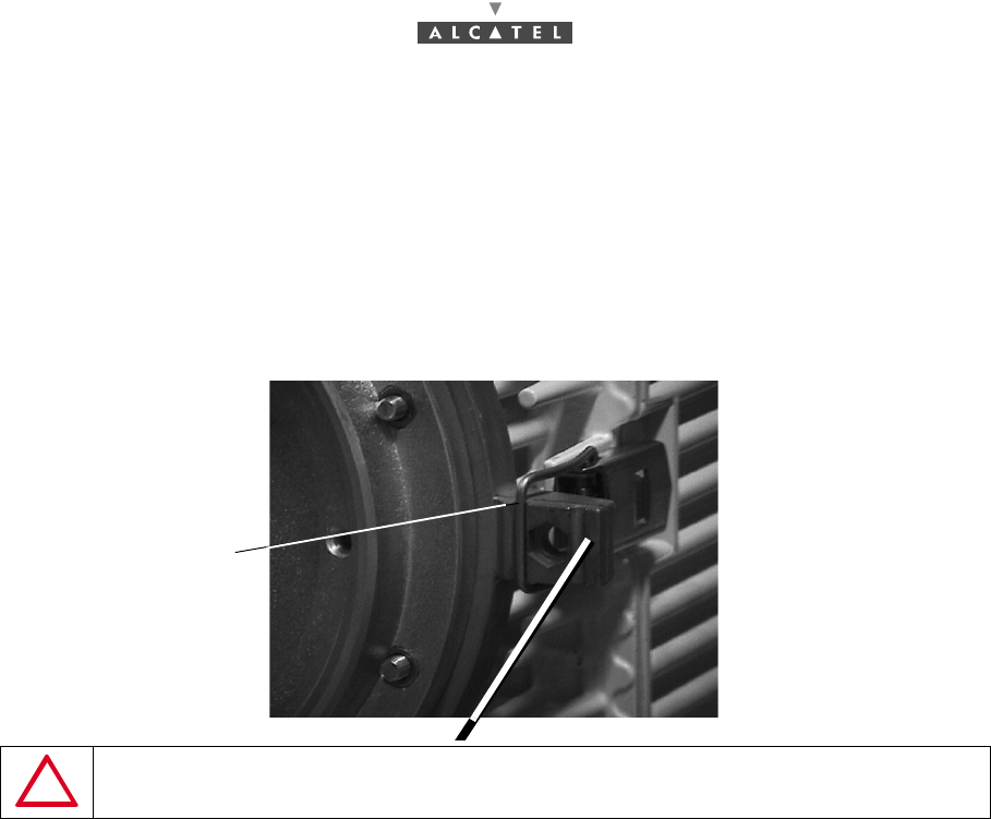
1. Remove the two transparent plastic protective caps : that of the antenna and that of the RBS unit.
Figure 28 – RBS and antenna nose
2. Take the transceiver by the handle and place the two bosses in the "nose" of the unit against the two
IMPORTANT: THE RADIO UNIT ASSEMBLY MUST ALWAYS BE
MANIPULATED BY ITS HANDLE ONLY.
IMPORTANT: REMOVE THE CAP WITH CARE, TAKING CARE NOT TO DAMAGE THE
SEAL WINDOW AT THE BOTTOM OF THE GUIDE.
IMPORTANT: THE O-RING SEAL (SEE Figure 26 – Antenna nose) SHOULD BE COATED
BEFORE SETTING (SILICON GREASE PROVIDED WITH THE ANTENNA).
Transceiver side
antenna side
2
1
3
guides
seal window at the
bottom of the guide
"Antennanose" slots N point
3CC12424AAAA TQ BJA 01 Issue 01 - April 2001 - Draft 04 53/302
76
slots in the "nose" of the antenna.
Note: the RBS-DBS link cable (N point) should be towards the base of the transceiver.
Note: the sectored antenna must be placed with the TOP marking uppermost, the antenna "nose" slots
coinciding with those of the RBS.
The waveguide needs to be positioned so that it is aligned with the antenna’s rectangular orifice.
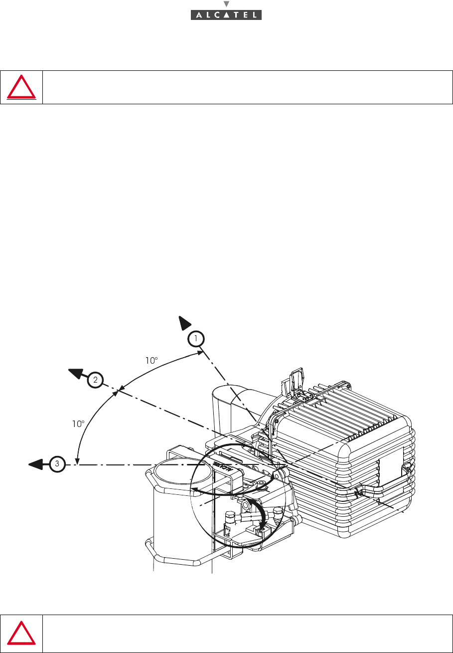
3. While holding the radio unit, begin by locking (See Figure 29 – Locking the Radio unit) the two side
snap-locks on the support, then that at the bottom, followed by that at the top.
Figure 29 – Locking the Radio unit
REMINDER: The RBS/antenna assembly requires no additional seal on the SHF flanges; the two
ends are smooth. Sealing is provided by the O-ring seal around the male "noses" (see Figure 26 –
Antenna nose).
NEVER USE THE EXTERNAL KAYWAYS TO LOCK THE RADIO UNIT.
Right locking position
54/302 Issue 01 - April 2001 - Draft 04 3CC12424AAAA TQ BJA 01
76
3.3.6 Antenna alignment
3.3.6.1 Deflection characteristics
The deflection obtained with the turnbuckles is : elevation = ± 25° and bearing = ± 10°.
3.3.6.2 Definitions about antenna alignment
Tilt or Elevation : angle of tilt from the horizontal.
Tilt UP : the antenna points upwards.
Tilt 0 : the antenna is horizontal.
Tilt DOWN : the antenna points downwards.
3.3.6.3 Coarse azimutal alignment of the antenna
The azimutal coarse alignment has to be carried out when installing the pole mounting.
Figure 30 – Azimutal alignement of antenna
REMINDER: THE RADIO UNIT/ANTENNA ASSEMBLY MUST ALWAYS BE
MANIPULATED BY THE RADIO UNIT’S HANDLE ONLY.
CAUTION: THE BRACKET NUTS MUST BE FASTENED TO TORQUE OF 3 mdaN,
± 10%. THE TUBE AND THE BRACKETS MUST BE CLEAN AND WITHOUT
GREASE, EXCEPT ON THE THREADS.
3CC12424AAAA TQ BJA 01 Issue 01 - April 2001 - Draft 04 55/302
76
3.3.6.4 Coarse azimutal alignment of the antenna
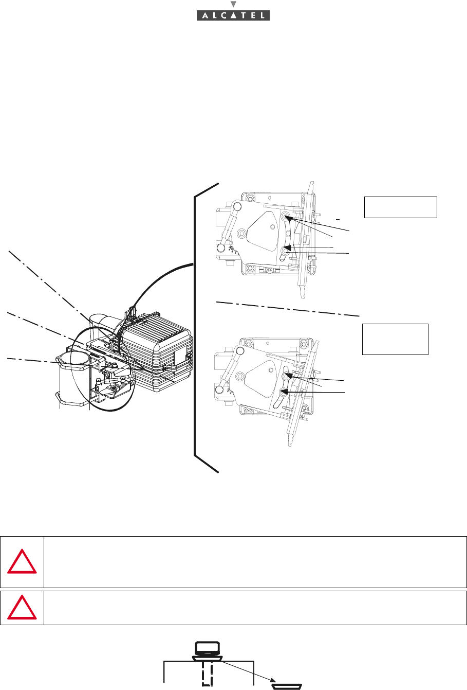
The elevation alignment is performed only with the elevation turnbuckles. If the elevation angle is higher
that (+ 5°) or lower than (- 5°), it is necessary to:
–remove completely one of the 2 screws fixing the antenna support on the azimut support and,
–insert it in the third hole accessible as shown in the Figure 31 – Elevation coarse alignement of
antenna.
Figure 31 – Elevation coarse alignement of antenna
CAUTION: IN ALL CASES, THE SUPPORT MUST BE FIXED WITH 3 SCREWS,
2 PUT IN THE WINDOW AND 1 CORRESPONDING TO ITS AXIS OF ROTATION.
ALL SCREWS MUST BE TIGHTENED AND SECURED ONLY AFTER THE END
OF THE ALIGNMENT OF ANTENNA.
CAUTION: TAKE CARE TO PUT THE 2 SCREWS IN THE WINDOW WITH THE
FLAT WASHERS POSITIONED AS SHOWN IS THE FIGURE BELOW.
Put the screws in the
holes.
Put the screws
holes
i.e. the the window,
in the 2
and the
visible
hole.
through
external
two external
middle
α = 25°
α = 25°
If: -5° < α < 5°
If: α > 5°
or: α < - 5°