Cisco Systems BTS-R3 Broadband Data BTS User Manual ttaicguide
Cisco Systems, Inc Broadband Data BTS ttaicguide
Contents
Guide 1

Ripwave™ Base Station
Installation & Commissioning Guide
Part Number 40-00047-00
Revision D, Version 1.0
February 28, 2003
Proprietary
All information disclosed by this document is the proprietary property of Navini Networks, Inc. and is protected by
copyright, trademark, and/or trade secret laws. All rights therein are expressly reserved.

Ripwave Base Station I&C Guide Navini Networks, Inc.
2 Part #40-00047-00 Rev D v1.0
February 28, 2003
About This Document
Purpose
This document provides a Navini-certified Installation & Commissioning Technician with
instructions to properly install the Base Transceiver Station, Radio Frequency Subsystem, and
cabling; and to test and commission the Base Station after installation.
Revision History
Date Revision/Version Authors Editors Comments
2001 A/1.0 J. Price
C. Keltner
A. Chua
P. Blain
J. Coulson
D. Karina
K. Sharp
L. Hoffman
N/A Draft
4.02 B/v1.0 Same N/A Preliminary
8.30.02 C/1.0 Same N/A Prepare for release 1.16
9.3.02 C/1.0 Same S. Redfoot Review comments from class 8.30.02
9.27.02 C/1.0 Same Same Preliminary Commercial Release 1.18
10.18.02 C/1.0 Same Same Feedback on forms and specifications
2.7.03 D/1.0 Same Same Combined all Base Station I&C into one
manual; Preliminary 1.19
2.28.03 D/1.0 Same Same Standard Release 1.19
Contacts
Contact Navini Networks Technical Support during normal business hours: Monday through
Friday 8:30 a.m. to 5:30 p.m. Central Time. You can also submit questions or comments by web
or email at any time.
Corporate Headquarters: (972) 852-4200
Technical Support: 1-866-RIPWAVE
Web Address: www.navini.com / select Technical Support
E-mail: techsupport@navini.com
Navini Networks, Inc.
2240 Campbell Creek Blvd.
Suite 110
Richardson, Texas 75082
USA

Navini Networks, Inc. Ripwave Base Station I&C Guide
Part #40-00047-00 Rev D v1.0 3
February 28, 2003
Permissions, Trademarks & Distribution
Copyright© February 2003, Navini Networks, Inc. All information contained herein and
disclosed by this document is the proprietary property of Navini Networks, Inc. and all rights
therein are expressly reserved. Acceptance of this material signifies agreement by the recipient
that the information contained in this document is confidential and that it will be used solely for
the purposes set forth herein. Acceptance of this material signifies agreement by the recipient
that it will not be used, reproduced in whole or in part, disclosed, distributed, or conveyed to
others in any manner or by any means – graphic, electronic, or mechanical, including
photocopying, recording, taping, or information storage and retrieval systems – without the
express written permission of Navini Networks, Inc.
Navini Networks, Internet at the Speed of Thought, zero-install, unwired by Navini, the Navini
Networks logo, and Ripwave are trademarks of Navini Networks, Inc. Other product and
company names mentioned herein may be trademarks and/or service marks of their respective
owners.
Nothing herein constitutes any representation, warranty, assurance, or guaranty of any
kind.
Because of continuing developments and improvements in design, manufacturing, and
deployment, material in this document is subject to change without notification and does not
represent any commitment or obligation on the part of Navini Networks, Inc.
Navini Networks, Inc. shall have no liability for any error or damages resulting from the use of
this document. Any unauthorized usage is strictly prohibited without the express written
permission of Navini Networks, Inc.
2003 Navini Networks, Inc. All rights reserved.
Navini Networks, Inc.
2240 Campbell Creek Boulevard
Suite 110
Richardson, Texas 75082
USA

Ripwave Base Station I&C Guide Navini Networks, Inc.
4 Part #40-00047-00 Rev D v1.0
February 28, 2003
TABLE OF CONTENTS
ABOUT THIS DOCUMENT.............................................................................................................. 2
PERMISSIONS, TRADEMARKS & DISTRIBUTION............................................................................ 3
SAFETY ........................................................................................................................................ 6
REGULATORY INFORMATION........................................................................................................ 8
BATTERY CAUTION & PROCEDURES ............................................................................................ 9
GLOSSARY OF TERMS & ABBREVIATIONS.................................................................................. 10
CHAPTER 1: OVERVIEW ...................................................................................................... 17
RIPWAVE DESCRIPTION .............................................................................................................. 17
PROCEDURAL DOCUMENTS & FORMS ........................................................................................ 18
I&C PROCESS FLOWCHART........................................................................................................ 19
BASE STATION COMPONENTS..................................................................................................... 29
GENERAL SPECIFICATIONS ......................................................................................................... 33
BASE STATION SPECIFICATIONS ................................................................................................. 34
MATERIALS SPECIFICATIONS...................................................................................................... 36
CHAPTER 2: INSTALLATION .............................................................................................. 39
PRE-INSTALLATION .................................................................................................................... 39
INSTALL POWER & GROUNDING ................................................................................................ 42
INSTALL CABLES ........................................................................................................................ 45
INSTALL THE BTS ...................................................................................................................... 50
INSTALL GPS ANTENNAS........................................................................................................... 55
INSTALL THE RFS....................................................................................................................... 58
VERIFY INSTALLED CIRCUIT CARDS .......................................................................................... 69
BASE STATION INSTALLATION CERTIFICATION .......................................................................... 70
CHAPTER 3: COMMISSIONING .......................................................................................... 71
REVIEW CUSTOMER NETWORK PLANS ....................................................................................... 71
INSTALL EMS SERVER............................................................................................................... 71
VERIFY CABLE CONNECTIONS ................................................................................................... 72
CONFIGURE & POWER UP THE BTS ...........................................................................................73
CALIBRATE THE BASE STATION ................................................................................................. 96
VERIFY THE CALIBRATION ....................................................................................................... 100
EXPORT BTS DATA.................................................................................................................. 110
PERFORM LOCAL CPE TESTS................................................................................................... 111
INSTALL & TEST CUSTOMER EMS OPERATIONS ..................................................................... 116
PERFORM CALIBRATION USING CUSTOMER’S EMS ................................................................. 116
VERIFY SYSTEM PERFORMANCE .............................................................................................. 117
VERIFY SYSTEM OPERATION WITH MULTIPLE CPE’S............................................................. 118
BACK UP EMS DATABASE....................................................................................................... 118
CUSTOMER ACCEPTANCE ......................................................................................................... 118

Navini Networks, Inc. Ripwave Base Station I&C Guide
Part #40-00047-00 Rev D v1.0 5
February 28, 2003
APPENDIX A: ORDERING DOCUMENTATION & FORMS ......................................... 119
APPENDIX B: SITE CANDIDATE EVALUATION FORM.............................................. 121
APPENDIX C: RFS SYSTEM TEST (CABLE SWEEPS) .................................................. 133
APPENDIX D: BASE STATION INSTALLATION CERTIFICATION .......................... 151
APPENDIX E: CONFIGURATION FORMS....................................................................... 154
APPENDIX F: BASE STATION CALIBRATION VERIFICATION* ............................. 175
APPENDIX G: DRIVE STUDY ............................................................................................. 183
APPENDIX H: LOCATION (FTP) TESTS .......................................................................... 188
APPENDIX I: CUSTOMER ACCEPTANCE ...................................................................... 195
APPENDIX J: OUTDOOR ENCLOSURES ......................................................................... 197
APPENDIX K: INSTALL CONNECTORS ON CABLES .................................................. 213
APPENDIX L: CHASSIS ALARMS...................................................................................... 215
APPENDIX M: ANTENNA DRAWINGS............................................................................. 217
APPENDIX N: RECTIFIER/BBU SPECIFICATIONS ......................................................219
APPENDIX O: SAMPLE BILL OF MATERIALS (BOM)................................................. 227
APPENDIX P: SAMPLE BASE STATION DRAWING .....................................................231
APPENDIX Q: SAMPLE STATEMENT OF WORK ......................................................... 233
APPENDIX R: SAMPLE RESPONSIBILITY ASSIGNMENT MATRIX (RAM)........... 237
LIST OF EXHIBITS................................................................................................................. 245
LIST OF FIGURES .................................................................................................................. 247
LIST OF TABLES .................................................................................................................... 249
`

Ripwave Base Station I&C Guide Navini Networks, Inc.
6 Part #40-00047-00 Rev D v1.0
February 28, 2003
Safety
To optimize safety and expedite installation and service, read this document thoroughly. Follow
all warnings, cautions, and instructions marked on the equipment and included in this document.
To aid in the prevention of injury and damage to property, cautionary symbols have been placed
in this document to alert the reader to known potentially hazardous situations, or hazards to
equipment or procedures. The symbols are placed before the information to which they apply.
However, any situation that involves heavy equipment and electricity can become hazardous, and
caution and safety should be practiced at all times when installing, servicing, or operating the
equipment.
Caution Symbol - possible equipment or property damage
Warning Symbol - could cause personal injury or otherwise be hazardous to
your health
Navini Networks, Inc., expressly requires that when using Navini electronic equipment always
follow the basic safety precautions to reduce the risk of electrical shock, fire, and injury to
people and/or property.
1. Follow all warnings and instructions that come with the equipment.
2. Do not use the equipment while you are in a bathtub, shower, pool, or spa. Exposure of the
equipment to water could cause severe electrical shock or serious damage to the equipment.
3. Do not allow any type of liquid to come in contact with the equipment. Unplug the
equipment from the power source before cleaning. Use a damp cloth for cleaning. Do not use
any soaps or liquid cleaners.
4. Follow all airport and FAA regulations when using the equipment on or near aircraft.
5. Only operate the equipment from the type of power source(s) indicated in this manual (110
VAC or Navini supplied battery). Any other type of input power source may cause damage to
the equipment.
6. Power the equipment using only the battery or the AC adapter cable provided, and in
accordance with the instructions specified in the User Guide.
7. Do not use a frayed or damaged power cord. Do not place the power cord where it can be
stepped on or tripped over.
8. Do not touch wires where the insulation is frayed or worn unless the equipment has been
disconnected from its power source.
9. Do not overload wall outlets, power strips, or extension cords. This can cause serious
electrical shock or fire.
10. Do not place the equipment on an unstable surface. It can fall and cause injury or damage to
the equipment.

Navini Networks, Inc. Ripwave Base Station I&C Guide
Part #40-00047-00 Rev D v1.0 7
February 28, 2003
11. Do not disassemble the equipment. Removing covers exposes dangerous voltages or other
risks and also voids the warranty. Incorrect reassembly can cause equipment damage or
electrical shock. Only an authorized repair technician should service this product.
12. Do not expose the equipment to extreme hot or cold temperatures.
13. Do not use the equipment under the following conditions:
• When the equipment has been exposed to water or moisture.
• When the equipment has been damaged.
• When the power cord is damaged or frayed.
• When the equipment does not operate properly or shows a distinct
change in performance.

Ripwave Base Station I&C Guide Navini Networks, Inc.
8 Part #40-00047-00 Rev D v1.0
February 28, 2003
Regulatory Information
FCC Notice
WARNING! This device is a Radio Frequency transmitter. It is required to comply with
FCC RF exposure requirements for transmitting devices. A minimum separation distance
of 8 inches (20 cm) or more must be maintained between the antenna and all persons
during device operations to ensure compliance with the FCC’s rules for Radio Frequency
Exposure. If this minimum distance cannot be maintained, exposure to RF levels that
exceed the FCC’s limits may result.
FCC Compliance and Advisory Statement
This equipment has been tested and found to comply with the limits for a class B digital
device, Pursuant to Part 15 of the FCC rules. The operation is subject to the following
two conditions:
(1) This device may not cause harmful interference, and
(2) This device must accept any interference received, including interference that may
cause undesired operation.
These limits are designed to provide reasonable protection against harmful interference in
a residential installation. This equipment generates, uses, and can radiate radio frequency
energy and, if not installed or used in accordance with the instructions, may cause
harmful interference to radio communications. However, there is no guarantee that
interference will not occur in a particular installation. If this equipment does cause
harmful interference to radio or television reception, which can be determined by turning
the equipment off and on, the user is encouraged to try to correct the interference by one
or more of the following measures:
(1) Reorient or relocate the receiving antenna;
(2) Increase the separation between the equipment and the receiver;
(3) Connect the equipment to an outlet on a circuit different from that to which the
receiver is connected;
(4) Consult the dealer or an experienced radio/TV technician for additional suggestions.
INFORMATION TO USER
This device has been authorized as a radio frequency transmitter under the appropriate
rules of the Federal Communications Commission. Any changes or modifications not
expressly approved by Navini Networks could void the user’s authority to operate the
equipment.
Tested To Comply
With FCC Standards
FOR HOME OR OFFICE US
E

Navini Networks, Inc. Ripwave Base Station I&C Guide
Part #40-00047-00 Rev D v1.0 9
February 28, 2003
Battery Caution & Procedures
WARNING! To reduce risk of injury or fire, follow these instructions when handling the
battery.
1. Risk of explosion is possible if the battery is replaced with one not supplied by Navini
Networks.
2. Do not dispose of the battery in a fire. It may explode. Check with the local codes for
battery disposal guidelines.
3. Do not open or mutilate the battery. The battery contains substances that are toxic,
corrosive, or harmful to humans. If battery substances come in contact with the skin,
seek medical help immediately.
4. Do not attempt to recharge the battery by any means except per the instructions in this
manual.
5. Remove the battery from the equipment if the equipment is not going to be used for a
long period of time. The battery could leak and cause damage to the equipment.
6. Exercise care when handling the battery to prevent shorting the battery with conducting
materials such as bracelets, rings, and keys.
7. Store the battery pack in a dry place, 0 to +40 degrees Celsius.
8. Dispose of used batteries according to environmental guidelines.

Ripwave Base Station I&C Guide Navini Networks, Inc.
10 Part #40-00047-00 Rev D v1.0
February 28, 2003
Glossary of Terms & Abbreviations
Term Stands For.... Meaning
802.11 802.11 Standard An IEEE LAN standard for wireless Ethernet replacement
technology in the ISM band. Runs at up to 10 Mbps.
ACC Access Channel or
Access Code Channel
AKA, Paging Channel. The signal path that tells a mobile to
prepare for an incoming call.
ACK Acknowledge Positive message sent by a protocol to acknowledge reception
of a transmitted packet
AP Access Point Wireless LAN transceiver that acts as a center point of an all-
wireless network or as a connection point between wireless and
wired networks.
ARP Address Resolution Protocol The function of the ARP is to match higher-level network IP
addresses with the physical hardware address of a piece of
equipment.
ASYNCH Asynchronous
N
ot occurring at regular intervals, as in data piped over a
network
ATM Asynchronous Transfer Mode Transporting a broad range of user data at irregular intervals
over network facilities
BB Broadband RF system with constant data rate of 1.5 Mbps or higher.
BCC Broadcast Code (or Control)
Channel
A channel of data transmitted by one entity and received by
many devices.
BS Base Station
N
etwork Access equipment and software that transmits and
receives, as well as processes, voice or data calls from mobile
units to network connections. A Ripwave Base Station consists
of the Base Transceiver Station (BTS) and the Radio
Frequency Subsystem (RFS), or antenna, plus a Global
Positioning System (GPS) antenna for timing.
BTS Base Transceiver Station The Ripwave BTS is a two-shelf rack that holds the RF
modules and digital circuit cards that interpret radio signals
into computer language and sends messages to and from the
local or wide area network. It functions between the RFS and
the EMS to handle the signaling.
BW Bandwidth Frequency spectrum usable for data transfers. It describes the
maximum data rate that a signal can attain on the medium
without encountering significant loss of power. Usually
expressed in bits per second (digital) or Hertz (analog).
BYTE Byte 8 bits
CAM Configuration & Alarm Manager An EMS functionality that is handled through a Graphical User
Interface for purposes of configuring elements in the system
and handling other OAM requirements.
CC 1Communications Controller or
2Cross-check
1A type of circuit card that resides in the Digital shelf of the
Ripwave BTS. It handles all interfaces between BTS and
network. 2An EMS functionality that allows the system to
perform an automated sanity check of the datafill.

Navini Networks, Inc. Ripwave Base Station I&C Guide
Part #40-00047-00 Rev D v1.0 11
February 28, 2003
Term Stands For.... Meaning
CD 1Compact Disk or 2Change Directory1An optical disk capable of storing large amounts of data (700x
floppy disk). It can be inserted into most pc’s and “read” to
load files onto a computer 2A software programming term in
“C” language that tells the computer to go to a different
location in the computer’s memory.
CDMA Code Division Multiple Access Digital cellular technology that uses a spread-spectrum
technique where individual conversations are encoded with a
random digital sequence. Increases capacity and speed of
communications messages between mobile units over other
types of wireless networks.
CD-ROM Compact Disk - Read Only Memory See “CD.” If a CD is not Read Only, computers can write data
to it with that capability.
CHP Channel Processor Card A card in the digital shelf of the BTS that performs the first
stage of signal processing for up to 4 antennae. One Navini 2.4
GHz BTS has 8 antennae. The card performs digital-to-analog
conversion (DAC) and analog-to-digital conversion (ADC) for
up to 10 carriers.
CLEC Competitive Local Exchange Carrier A telephone company that competes with an incumbent Local
Exchange Carrier (LEC).
CLI Command Line Interface A text-based programming language through which a user
communicates with an operating system or an application.
CORBA Common Object Request Broker
Agent
A standard for Network Management Systems that allows
integration with NMS regardless of programming language or
Operating System.
CPE Customer Premise Equipment Communications equipment that resides at the customer’s
location.
dB Decibel Unit of measurement for sound.
dBd Decibel/Dipole A ratio, measured in decibels, of the effective gain of an
antenna compared to a dipole antenna (2 horizontal rods in line
with each other). The greater the dBd value the higher the gain
and therefore the more acute the angle of coverage.
dBi Decibel/Isotropic A ratio, measured in decibels, of the effective gain of an
antenna compared to an isotropic antenna (measured along
axes in all directions). The greater the dBi value the higher the
gain and therefore the more acute the angle of coverage.
DHCP Dynamic Host Configuration
Protocol
A protocol for dynamically assigning IP addresses to devices
on a network.
DiffServ Differentiated Service Different Quality of Service (QoS) descriptions for different
types of traffic, i.e., voice, video, email. The DiffServ table is
where each level of QoS is defined. Equivalent to Class of
Service (COS) in POTS.
DIR Directory A special kind of file used to organize other files into a
hierarchical structure.
DL DownLink In this case, data messages transmitted from the BTS to the
CPE.
DNS Domain Name Server TCP/IP networking term that is a protocol for matching objects
to network (IP) addresses.
DS-1 Digital Signal - 1 Also “T1” or “E1”. Digital transmission equipment that can
handle up to 1.544 Mbps.
DSL Digital Subscriber Line A type of service whereby users gain access to the Internet
through high-speed data networks.

Ripwave Base Station I&C Guide Navini Networks, Inc.
12 Part #40-00047-00 Rev D v1.0
February 28, 2003
Term Stands For.... Meaning
DSP Digital Signal Processor Compressing or manipulating analog signals to digital signals
and vice-versa.
EID Equipment Identifier Field in EMS for assigning IP address or name to individual
pieces of equipment for purposes of configuring the system.
EMS Element Management System An application that allows the user to define and manipulate
managed objects as a system within an overall network.
ERP Effective Radiated Power The actual power in Watts radiated from a transmitter’s
antenna.
FCC Federal Communications
Commission
United States government regulatory agency that supervises,
licenses and otherwise controls electronic and electromagnetic
transmission standards.
FE Far End A relative term that refers to the receiving element in a
network, as opposed to the near-end element that is
transmitting data.
FTP File Transfer Protocol A TCP/IP method consisting of a client and server and used to
transfer files between two or more sites or elements in a
network.
Gain Gain Ratio of the output amplitude of a signal to the input amplitude
of a signal, expressed in decibels (dB).
Gb Gigabit One billion (1,000,000,000) bits.
GB Gigabyte One billion (1,000,000,000) bytes.
GHz Gigahertz One billion (1,000,000,000) hertz - cycles per second. Ultra
high frequency (UHF) signals, including microwave signals.
GPS Global Positioning System A constellation of 24 well-spaced satellites that orbit the earth
and enable users with GPS antennas to pinpoint their exact
geographical position.
GUI Graphical User Interface A graphic rather than purely text based user interface to a
computer or computing system.
HW Hardware Physical, tangible equipment
Hz Hertz 1 cycle per second.
I&C Installation & Commissioning Term used to describe the procedures of physically installing
technical equipment then powering up the equipment to make
sure it will operate (to put it “into commission”).
IEC Inter-exchange Carrier Also IXC. Public switching network service provider (carrier)
that connects across and between local exchange carriers
(LEC).
IF Interface Card Card on the digital shelf of the Ripwave BTS that takes the
analog signal from the Channel Processor card (CHP) and
converts it to a baseband signal before sending it on to the RF
modules for transmission (forward link), and vice-versa
(reverse link).
IMA Inverse Multiplexing over ATM A method of building dynamic routes of 2 or more T1’s to
increase bandwidth so that PVC’s can share the IMA
resources, as needed, for data transmissions.
IP Internet Protocol A TCP/IP protocol used to route data from its source to its
destination.
ISP Internet Service Provider A company that provides access to the Internet.
Kb Kilobit 1,024 bits
KB Kilobyte 1,024 bytes
KHz Kilohertz 1,000 hertz.

Navini Networks, Inc. Ripwave Base Station I&C Guide
Part #40-00047-00 Rev D v1.0 13
February 28, 2003
Term Stands For.... Meaning
L1 Layer 1 Physical Layer. Part of the OSI rules and standards for network
management. L1 describes the physical layer, or electrical and
mechanical port-to-port connections, in the network.
L2 Layer 2 Data Link Layer. Part of the OSI rules and standards for network
management. L2 describes the data link layer where data is set up
and torn down in a specific format (frames), through the overall
network. Also responsible for detecting and correcting errors by
requesting retransmission.
L3 Layer 3
N
etwork Layer. Part of the OSI rules and standards for network
management. L3 describes the network addressing that gets data
to its destination within the network, i.e., IP addressing.
LAN Local Area Network A data network of interconnected computers, servers, printers,
and other peripherals that communicate at high speeds over short
distances, usually within the same building. Also allows for
sharing of resources.
LCP Link Control Protocol Basis of the Point-to-Point Protocol (PPP) scheme for negotiating
and establishing connections.
LED Light-emitting Diode An electronic device that lights up when electricity passes
through it. Often used to indicate equipment or system state.
LLC Logical Link Controller A protocol that governs the transition of frames between data
stations regardless of how the medium is shared. It’s the upper
sub-layer that further defines the Media Access Control (MAC)
protocol. It provides the basis for an unacknowledged
connectionless service on a LAN - i.e., error correction,
multiplexing, broadcasting.
LOS Line-of-sight Describes laser, microwave, RF, and infrared transmission
systems that require no obstruction in a direct path between the
transmitter and the receiver.
MAC Media Access Control Protocol that governs access to a network in order to transmit
data between nodes. In a wireless LAN, the MAC is the radio
controller protocol (L2).
Mb Megabit One million (1,000,000) bits.
MB Megabyte One million bytes. Literally - 1,048,576 bytes.
Mbps Megabits Per Second Transmission speed at rate of one million bytes per second.
MDM Modem Card A card in the Navini BTS that converts digital signals into analog
so the signals can be transmitted over telephone lines, and vice-
versa. Modem stands for modulator/demodulator.
MHz Megahertz One million (1,000,000) hertz - cycles per second. Normally used
to refer to how fast a microprocessor can execute instructions.
MIB Management Information Base A collection of managed objects used in SNMP-based networks.
MIB’s carry information in a standard format so external tools
can analyze network management and performance.
MMDS Multipoint Multi-channel
Distribution Service
Fixed wireless, high-speed local service that operates at 2.1 - 2.7
GHz. Speed 10 Mbps. Originally conceived for cable TV service.
NE 1Near-end or 2Network Element 1The transmitting end, versus the receiving end, of a signal
transmission. 2 A router, switch, or hub in an ISDN network.
NLOS
N
on Line-of-site Describes laser, microwave, RF, and infrared transmission
systems that can penetrate obstructions in the path between the
transmitter and the receiver.

Ripwave Base Station I&C Guide Navini Networks, Inc.
14 Part #40-00047-00 Rev D v1.0
February 28, 2003
Term Stands For.... Meaning
NMS
N
etwork Management Syste
m
A product that helps manage a network generally hosted on a
well-equipped computer such as an engineering workstation. The
system tracks network statistics and resources.
NOC
N
etwork Operations Cente
r
A centralized point, much like a traffic control tower, where
technicians or engineers can monitor network activity, alarms,
and statistics, as well as make network configuration and other
changes dynamically. For Internet, the NOC is often a hub for
ISP services.
OAM Operation, Administration,
Maintenance
A set of network management functions. Also describes the
human-machine interface tasks - i.e., to operate the system, to
administer the system, and to maintain the system.
OS Operating System A software program that manages the basic operation of a
computer. Most Operating Systems are either based on
OSI Open Systems Interconnection An ISO model for worldwide communications that defines 7
layers of network protocol: L1 Physical Layer; L2 Data Link
Layer; L3 Network Layer; L4 Transport Layer; L5 Session
Layer; L6 Presentation Layer; L7 Application Layer.
PC Personal Computer Any IBM-compatible computer, so named because IBM’s first
commercial end user computer was called a PC.
PCB Printed Circuit Board A hardware module that holds electronic circuitry and usually
fits into a larger frame where the various PCB’s are
interconnected electronically.
PDU Packet Data Unit or Protocol Data
Unit
A data packet. Refers to that which is exchanged between peer-
layer entities. Contains header, data, and trailer information.
Ping Ping Generalized term from sonar science, where a short sound burst
is sent out and an echo or “ping” is received. Used to determine
if signals or packets have been dropped, duplicated, or reordered.
PPPoE Point-to-point Protocol Over
Ethernet
A protocol that allows dial-up Internet connections. Includes the
Link Control Protocol as well as Network Control Protocols.
Propagation Propagation To spread out and affect a greater area; travel through space, as
in radio waves.
PSK Phase Shift Keying Digital transmission term that means an angle modulation where
the phase of the carrier varies in relation to a reference or former
phase. An encoded shift. Each change of phase carries one bit of
information, where the bit rate equals the modulation rate.
PSN Packet Switched Network A network in which data is transferred in units called packets.
Packets can be routed individually and reassembled to form a
complete message at the definition.
PSTN Public Switched Telephone
N
etwor
k
Typically used in the same context as POTS. Analogous to a
network of major highways originally built by a single
organization but added to and expanded by multiple
organizations. AKA, backbone networks.
QAM Quadrature Amplitude ModulationA bandwidth conservation process routinely used in modems.
Creates higher throughput but decreased coverage area.
QoS Quality of Service A guaranteed throughput for critical network applications, such
as Voice over IP. Term primarily used in an ATM environment.
Five classes of service: Class 1 Video; Class 2 Audio; Class 3
Data Connection.

Navini Networks, Inc. Ripwave Base Station I&C Guide
Part #40-00047-00 Rev D v1.0 15
February 28, 2003
Term Stands For.... Meaning
RAM Random Access Memory Computer memory that can be accessed randomly.
RF Radio Frequency A portion of the electromagnetic spectrum in the frequency
range between audio and infrared: 100 KHz to 20 GHz. RF
measurements are expressed in Hz (unit for measuring
frequency); MHz = 1 Million Hz; GHz = 1 Billing Hz.
RFS Radio Frequency Subsystem A term for the antenna portion of the base station.
RSSI Receiver Signal Strength Indicator A term that describes the measure of the signal strength in
kilohertz or gigahertz between the transmission and the receiving
end.
Rx Receive An abbreviated way of expressing the term, receive, as in to
receive a transmission.
S-CDMA Synchronous Code Division
Multiple Access
Wireless technology based on data being transferred at a fixed
rate using Code Division Multiple Access algorithms.
SMDS Switched Multi-megabit Data
Service
Connectionless service for MAN/WAN based on 53-
b
yte packets
that target the interconnection of different LAN’s into a public
switched network at speeds higher than T1.
SMS 1Short Message Service or
2Systems Management Server
1A protocol that allows mobile users to send text-
b
ased messages
from one device to another. The text appears on a device’s screen
and may be a maximum 160 characters in length. 2A Windows
N
T process that allows a network administrator to inventory all
hardware and software on the network, then perform software
distribution over the LAN.
SNMP Simple Network Management
Protocol
Standard management request-reply protocol for managing
TCP/IP networks. A device is said to be SNMP compatible if it
can be monitored or controlled using SNMP messages.
SNR Signal-to-noise Ratio Related to RSSI, a measurement of the intended signal being
transmitted against the other entities that can interfere with the
signal.
SO/HO Small Office/Home Office Small, remote office with a MAN or WAN connection back to a
larger corporate network and/or the Internet.
SSI Signal Strength Indicator See “RSSI”.
SW Software Computer instructions or data.
SYN Synthesizer Card A circuit card in the Navini BTS digital shelf that provides a
local oscillator and system clock with a single calibration
transceiver. The card is used to calibrate the Base Station so that
no external spectrum analyzer or signal generator is required.
SYNCH Synchronous Digital packets or signals that are sent at the same, precisely
clocked fixed rate of speed.
TCC 1Traffic Channel or 2Transmission
Control Code
1A portion of a radio channel used to enable transmission of one
direction of a digitized voice conversation (as opposed to the
Voice Channel). 2A way of segregating traffic in order to define
controlled communities of interest among subscribers.
TCP Transport Control Protocol A standardized transport protocol between IP-based network
nodes that allows two hosts to establish a connection and
exchange streams of data. TCP operates on top of Internet
Protocols and handles the multiplexing of sessions, error
recovery, reliability and flow; it guarantees packets are delivered
in the same order in which they were sent.
TCP/IP Transport Control
Protocol/Internet Protocol
A set of protocols that allows cooperating computers to share
resources across the network. TCP provides the reliability in the
transmission, while IP provides connectionless packet service.

Ripwave Base Station I&C Guide Navini Networks, Inc.
16 Part #40-00047-00 Rev D v1.0
February 28, 2003
Term Stands For.... Meaning
TDD Time Division Duplex A digital transmission method that combines signals from
multiple sources and allows a single channel to alternately carry
data in each direction of a link.
TFFS True Flash File System Memory in a computing device that does not lose its information
when powered off. Available as a SIMM or PCMCIA card, it
usually stores router Operating System (OS) software. Can be
easily updated.
TTL Time-to-live A field in the Internet Protocol that specifies how many more
hops a packet can travel before being discarded or returned.
Tx Transmit To send by wire or other medium electronically or through air
via electromagnetic waves to a receiving communications device.
UL UpLink Describes the direction of signal flow being sent from a
subscriber to a network system, as in from a mobile device (CPE)
to a base station.
USB Universal Serial Bus An external bus standard for plug-and-play interfaces between a
computer and add-on devices, such as a mouse, modem,
keyboard, etc. One USB port can connect up to 127 devices.
VCC Virtual Channel Circuit AKA, Virtual Channel Connection or Virtual Circuit Connection.
A logical circuit made up of Virtual Channel Links, which carry
data between two end points in an ATM network.
VCI Virtual Channel Identifier A 16-bit value in the ATM cell header that provides a unique
identifier for the Virtual Channel that carries that particular cell.
VCL Virtual Channel Link A connection between two ATM devices.
Vector Vector A quantity representative of both magnitude and direction
(energy + orientation in space)
VPC Virtual Private Channel AKA, Virtual Path Connection. A grouping of Virtual Channel
Connectors, which share one or more contiguous VPL’s.
VP Virtual Path A set of Virtual Channels grouped together between cross-points
(i.e., switches).
VPI Virtual Path Identifier An 8-bit value in the cell header that identifies the VP as well as
the VC to which the cell belongs. The VPI + VCI identify the
next destination of a cell as it passes through a series of ATM
switches.
VPL Virtual Path Link A group of unidirectional VCL’s with the same end points in a
Virtual Path. Grouping VCL’s into VPL’s reduces the number of
connections to be managed. One or more VPL’s makes up a
VPC.
WAN 1Wide Area Network or
2Wireless Access Network
1A communications network that spans geographically separate
areas and which provide long-haul services. Examples of inter-
networked connections are frame relay, SMDS, and X.25
protocols. 2 General term for any product primarily used to gain
access to the Internet, as opposed to being part of the actual
Internet devices or software.
Navini Networks, Inc. Ripwave Base Station I&C Guide
Part #40-00047-00 Rev D v1.0 17
February 28, 2003
Chapter 1: Overview
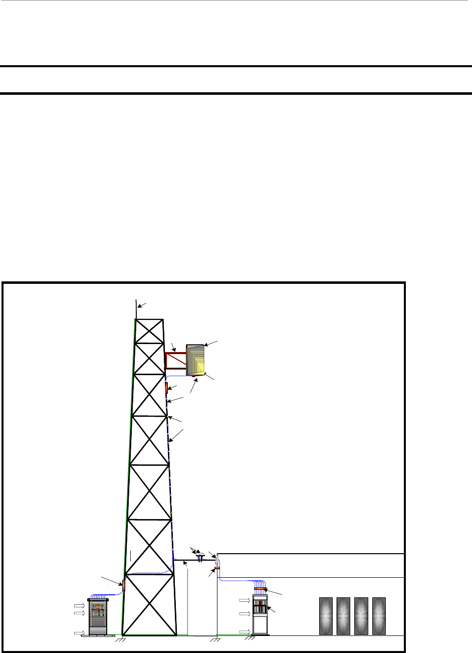
Ripwave Description
A Ripwave system has three main components: the Customer Premise Equipment (CPE); the
Base Station; and the Element Management System (EMS). The Base Station performs the CPE
registration and call processing, and provides the interface between the backhaul network and the
EMS. It is made up of the Base Transceiver Station (BTS) and the Radio Frequency Subsystem
(RFS) (Figure 1). This manual provides the guidelines and instructions for installing and
commissioning (I&C) the Base Station.
Figure 1: Base Station Installation With Panel Antenna
LIGHTNING
ROD
GPS
ETHERNET
/ TELCO
OVERHEAD
CABLE LADDER
SHELTER / HUT
SELF SUPPORTING
GUIDE
ANTENNA TOWER
PANEL
ANTENNA
ANTENNA
BRACKET
PSX-ME
SURGE
PROTECTOR
GROUND
BAR
RF CABLES
CABLE
HANGERS
CABLE
LADDER
CABLE
ENTRY
GROUND
BAR
OPTION 1
INDOOR BTS
PSX
GROUND BAR
24VDC
@ 60A
CABINET
GND
PSXGROUND BAR
NAVINI
BTS
ETHERNET
TELCO
24VDC @ 60A
CABINET
GND
OPTION 2
OUTDOOR BTS
Note: The illustration shows both
an outdoor and an indoor BTS,
but only one panel antenna. In
reality, each BTS requires
its own panel.
LIGHTNING
ROD
GPS
ETHERNET
/ TELCO
OVERHEAD
CABLE LADDER
SHELTER / HUT
SELF SUPPORTING
GUIDE
ANTENNA TOWER
PANEL
ANTENNA
ANTENNA
BRACKET
PSX-ME
SURGE
PROTECTOR
GROUND
BAR
RF CABLES
CABLE
HANGERS
CABLE
LADDER
CABLE
ENTRY
GROUND
BAR
OPTION 1
INDOOR BTS
PSX
GROUND BAR
24VDC
@ 60A
CABINET
GND
PSXGROUND BAR
NAVINI
BTS
ETHERNET
TELCO
24VDC @ 60A
CABINET
GND
OPTION 2
OUTDOOR BTS
Note: The illustration shows both
an outdoor and an indoor BTS,
but only one panel antenna. In
reality, each BTS requires
its own panel.

Ripwave Base Station I&C Guide Navini Networks, Inc.
18 Part #40-00047-00 Rev D v1.0
February 28, 2003
Procedural Documents & Forms
You will refer to other Ripwave documents, procedures, and forms in the process of installing
and commissioning the Base Station. They are listed in Appendix A of this manual. The product
documentation is provided on the Ripwave Standard Documentation CD (Table 1). As well, the
EMS manuals can be viewed on-line through the EMS Server and Client applications.
Table 1: Ripwave Standard Documentation CD
Order Number 95-00116-00 Component or
Part Number
Format
EMS Overview Manual 40-00016-03 MSWord/.pdf
EMS Software Installation 40-00017-00 MS Word/.pdf
EMS Administration Guide 40-00031-00 MS Word/.pdf
Ripwave Configuration Guide 40-00016-01 MS Word/.pdf
EMS CLI Reference Manual 40-00016-02 MS Word/.pdf
Ripwave Alarm Resolution Reference Manual 40-00033-00 MS Word/.pdf
Ripwave Base Station Operations & Maintenance Guide 00-00046-00 MS Word/.pdf
Ripwave RFS Configuration Quick Guide 40-00067-00 MS Word/.pdf
EMS Diagnostic Tools Guide 40-00032-00 MS Word/.pdf
Ripwave Modem Quick Installation Guide 40-00112-00 MS Word/.pdf
English 40-00098-00 MS Word/.pdf
Spanish 40-00096-00 MS Word/.pdf
Ripwave Modem User Guide 40-00111-00 MS Word/.pdf
English 40-00097-00 MS Word/.pdf
Spanish 40-00099-00 MS Word/.pdf
Ripwave Modem Software Update Tool Guide 40-00066-00 MS Word/.pdf
A separate CD specifically created for personnel involved with installation and commissioning
of the Ripwave system, called “VAR I&C Documentation”, may be ordered by authorized
business partners and customers. The CD includes detailed procedures and electronic forms that
are used during the I&C process. Table 2 contains a partial listing of the files on this CD, while
Appendix A provides the complete list. The I&C forms found on the CD are referenced
throughout this manual, and copies are included in the appendices.
Table 2: VAR I&C Documentation CD
Order Number 95-00017-00 Part Number Format
RFS Omni & Panel Data Sheets 44-00037/38-00 Excel (includes drawings)
Site Candidate Evaluation Form 40-00091-00 Excel Spreadsheet
RFS System Test Form 40-00093-00 Excel Spreadsheet
Base Station Calibration Verification Form 40-00059-00 Excel Spreadsheet
Drive Study Survey Form 40-00076-00 Excel Spreadsheet
Location (FTP) Test Form 40-00077-00 Excel Spreadsheet
Customer Acceptance Form 40-00117-00 MS Word Document
BTS Outdoor Selection Guide 44-00035-00 MS Word Document
Rectifier/Battery Backup Specification 44-00036-00 MS Word Document

Navini Networks, Inc. Ripwave Base Station I&C Guide
Part #40-00047-00 Rev D v1.0 19
February 28, 2003
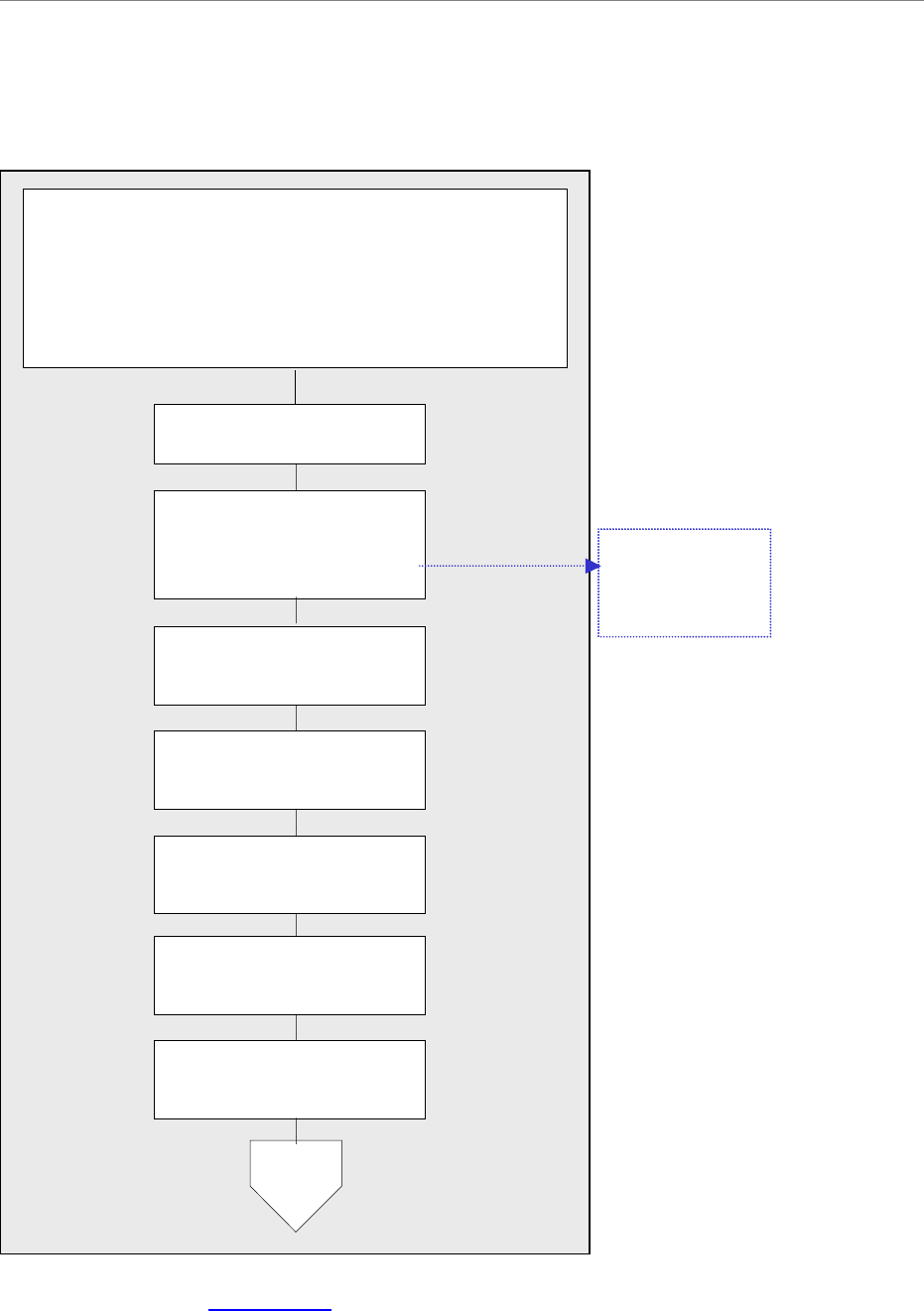
I&C Process Flowchart
To put the I&C activities in the context of overall system deployment, Figure 2 provides a ‘flow’
of the key activities that are performed prior to and during the installation and commissioning of
the Ripwave Base Station. Post-I&C, the system that has been installed and commissioned goes
through Acceptance Testing against the customer’s objectives for that site. Once customer sign-
off on the site is achieved, the customer becomes fully responsible for operating the system.
Different job holders may perform various portions of these activities and not necessarily all of
the activities. In fact, Marketing and Engineering personnel typically handle the earlier tasks,
while installation may be a stand-alone function. Commissioning may or may not be handled by
the same people who designed or installed the site. Regardless of who does them, these key
activities have to be accomplished for successful deployment:
• Site Engineering
• Installation
• Commissioning
• Acceptance Testing and sign-off
Prior to installation, Navini and the customer formulate a Project Plan and Responsibility
Assignment Matrix (RAM) to clarify who will do what to complete the I&C activities. If
requested by the customer, Navini may provide personnel, procedures, forms, and/or tools
required to install and commission the Base Station equipment. They may also provide special
commissioning software programs, computers, and any other special test equipment required.
As part of the I&C duties, all testing results are recorded and kept for the customer to review and
approve. These test results include the cable sweeps, the BTS Calibration Verification, RF
System Tests, Drive Study, Line-of-Sight (LOS) FTP tests, and Non-Line-of-Sight (NLOS) FTP
test results. The I&C Supervisor provides site tracking and weekly status reports. All of these
tasks can be negotiated with the customer.
If Navini Networks is hired by a customer to provide Installation & Commissioning Services,
involvement and some actual deliverables are still required by the customer. For example, the
customer will need to review or perhaps even explain their Site Design Specifications, approve
Logistics Plans, provide shipping information, approve the Network Architecture Plan, etc.
As part of a successful hand-off from Navini to the customer, it is usually necessary for Navini to
provide some product training to customer personnel who will support the Base Station operation
on-going. Customers may opt to take on a Train-the-Trainer program, in which case Navini
certifies the customer’s instructors who then provide staff training thereafter.

Ripwave Base Station I&C Guide Navini Networks, Inc.
20 Part #40-00047-00 Rev D v1.0
February 28, 2003
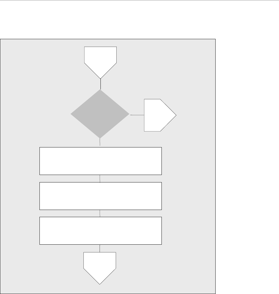
Figure 2: I&C Process Flowchart
Click here to link to Appendix B or to Appendix P.
3-Conduct site survey
& complete the Site
Candidate Evaluation Form.
Complete the Interference
Analysis/CPE Site Survey
Tool.
6-Develop Bill of Materials
(BOM)
7-Acquire materials
4-Acquire chosen customer
site information
8-Confirm customer
backhaul & EMS Server
Hardware & FTP Server
are installed & operational
2-Generate coverage
prediction map
5-Perform Network
Architecture design
1-Complete Project Plan
for customer
Site Engineering
Appendix B:
Site Candidate
Evaluation Form
End
Sample BoM provided
in Appendix P
Navini Networks, Inc. Ripwave Base Station I&C Guide
Part #40-00047-00 Rev D v1.0 21
February 28, 2003
Figure 2: I&C Process Flowchart, cont’d.
Click here to link to Appendix C.
3-Install & sweep RF
cables. Record results on
RFS System Test Form.
4-Install & sweep
GPS cables
5-Test & install
data/power cable
7-Install BTS chassis
2-Install all system buss
bars & surge protectors
6- If required, install
BTS mounting rack
8-Install & verify
BTS & RFS grounding
A
Installation
Appendix C:
RFS System
Test Form
1-From shipping containers received at
customer site, gather Manufacturing’s inventory
sheet & test data collected from the BTS & RFS
equipment shipped. Verify all equipment arrived,
the test data is available, & serial numbers match
paperwork. Keep as part of customer site records.

Ripwave Base Station I&C Guide Navini Networks, Inc.
22 Part #40-00047-00 Rev D v1.0
February 28, 2003
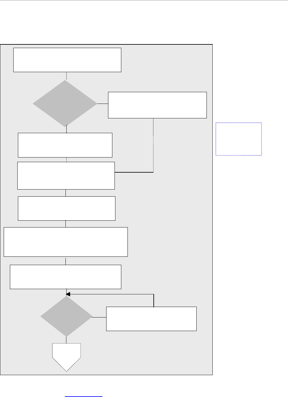
Figure 2: I&C Process Flowchart, cont’d.
Click here to link to Appendix D.
16-If required in Responsibility Assignment
Matrix (RAM), test the backhaul to the
customer demarcation point.
15-Record serial numbers & version
numbers of digital & PA cards on the Base
Station Installation Certification Form.
14-Verify digital cards & PA cards are
installed & seated properly.
12-Install RFS & surge protectors.
Connect 9 RF cables & data/power
cable to the RFS.
13-Sweep installed RFS & cables to verify
connections & cable loss. Record results on
RFS System Test Form.
11-Sweep the RFS. Record the results
and the RFS serial numbers on the RFS
System Test Form.
A
B
Appendix D:
Base Station
Installation
Certification
Form
9-Install & verify DC
input power source to BTS
10-Install GPS antennas
Navini Networks, Inc. Ripwave Base Station I&C Guide
Part #40-00047-00 Rev D v1.0 23
February 28, 2003
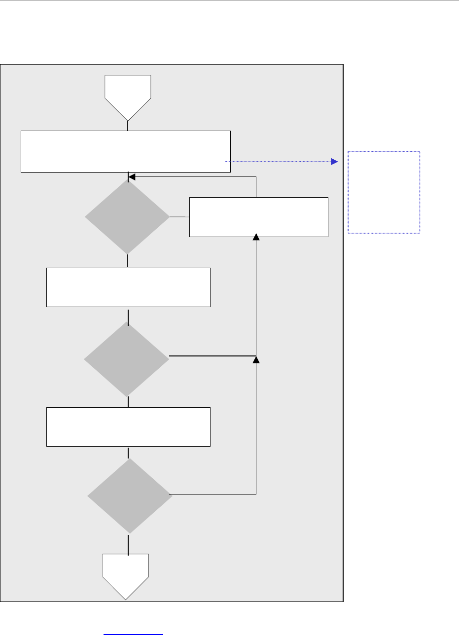
Figure 2: I&C Process Flowchart, cont’d.
17-Provide printed package of measured
results & equipment inventory to
customer on-site.
End
18-Go over results using forms &` get
customer sign-off on Installation using
Base Station Site Installation Form.
B
17-Provide printed package of measured
results & equipment inventory to
customer on-site.
End
18-Go over results using forms &` get
customer sign-off on Installation using
Base Station Site Installation Form.
B
Ripwave Base Station I&C Guide Navini Networks, Inc.
24 Part #40-00047-00 Rev D v1.0
February 28, 2003
Figure 2: I&C Process Flowchart, cont’d.
Click here to link to Appendix E.
5-Verify all cables are
connected
2-Are you using
the customer
EMS Server
?
No
Yes
3a-Install & configure* the Test
EMS Server & Client. Connect
to the BTS.
3b-Install & configure* the
customer EMS Server &
Client. Connect to the BTS.
1-Review customer network plans
(i.e., T1 vs. Ethernet)
6-Power up BTS & reconfigure Boot
Line configuration data through the
serial port.
7-After BTS has been powered up
at least 15 minutes, perform
3 calibrations.
8-Pass
calibration
?
9a-Perform system
troubleshooting procedures.
No
Yes
A
Commissioning
*Appendix E:
Configuration
Data Forms
4-Enter the RFS configuration
by running the RFS script that
shipped with the antenna eqpt.
Navini Networks, Inc. Ripwave Base Station I&C Guide
Part #40-00047-00 Rev D v1.0 25
February 28, 2003
Figure 2: I&C Process Flowchart, cont’d.
Click here to link to Appendix F.
11b-Perform local “wireline”
CPE test
9b-Perform Base Station calibration
Verify and record measurements on the
Base Station Calibration Verification Form.
10-Pass
calibration
verification
?
11a-Perform system
troubleshooting procedures
No
Yes
A
13-Perform local over-the-air
(OTA) CPE test
12-Wireline
CPE test
pass
?
No
Yes
14-OTA
CPE test
pass
?
No
Yes
B
Appendix F:
Base Station
Calibration
Verification
Form
Ripwave Base Station I&C Guide Navini Networks, Inc.
26 Part #40-00047-00 Rev D v1.0
February 28, 2003
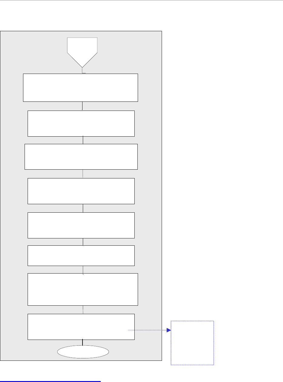
Figure 2: I&C Process Flowchart, cont’d.
17-Verify EMS Server
& BTS connectivity.
15-’Test’
EMS used
?
No
Yes
16-Install & configure the
customer EMS Server & Client.
Connect to the BTS.
B
D
C
18-Perform calibration. Ensure
successful results 3 times.
17-Verify EMS Server
& BTS connectivity.
15-’Test’
EMS used
?
No
Yes
16-Install & configure the
customer EMS Server & Client.
Connect to the BTS.
B
D
C
18-Perform calibration. Ensure
successful results 3 times.
Navini Networks, Inc. Ripwave Base Station I&C Guide
Part #40-00047-00 Rev D v1.0 27
February 28, 2003
Figure 2: I&C Process Flowchart, cont’d.
Click here to link to Appendix G.
Click here to link to Appendix H.
22-Send all preliminary test results
to Navini Technical Support
for evaluation.
24a-Adjust RF parameters &
troubleshoot. Go back to
Step 17, Perform calibration.
No
Yes
19*-Validate that the GPS & constellation
debugger are installed & operational on
the Drive Study computer. Perform
preliminary Drive Study. Record results
on the Drive Study Form.
23-Results
adequate
?
20-Perform preliminary LOS Location
(FTP) testing. Perform 3 uploads & 3
downloads at 3 locations. Record results on
the FTP Test Form.
D
C
E
Appendix G:
Drive Study
Form
Appendix H:
FTP Test
Form
*NOTE: Step 19 is performed
only if no RF plot is available.
21-Perform preliminary NLOS Location
(FTP) testing. Perform 3 uploads & 3
downloads at 3 locations. Record results on
the FTP Test Form.
Ripwave Base Station I&C Guide Navini Networks, Inc.
28 Part #40-00047-00 Rev D v1.0
February 28, 2003
Figure 2: I&C Process Flowchart, cont’d.
Click here to link to Appendix I.
28-Verify system operation with
multiple CPE devices.
27-Send test results to
Tech Support
29-Back up the EMS database
30-Gather all required documents &
forms to create a delivery package
for the customer sign-off & for the
Navini Technical Support database.
31-Participate in customer sign-off
of Customer Acceptance Form.
End
26-Perform full NLOS Location
(FTP) testing. Record results.
25-Perform full LOS Location
(FTP) testing. Record results.
E
Appendix I:
Customer
Acceptance
Form
24b-Perform full Drive Study, & record
results on the Drive Study Form.
This is used for tuning the model.
Navini Networks, Inc. Ripwave Base Station I&C Guide
Part #40-00047-00 Rev D v1.0 29
February 28, 2003
Base Station Components
Base Transceiver Station (BTS)
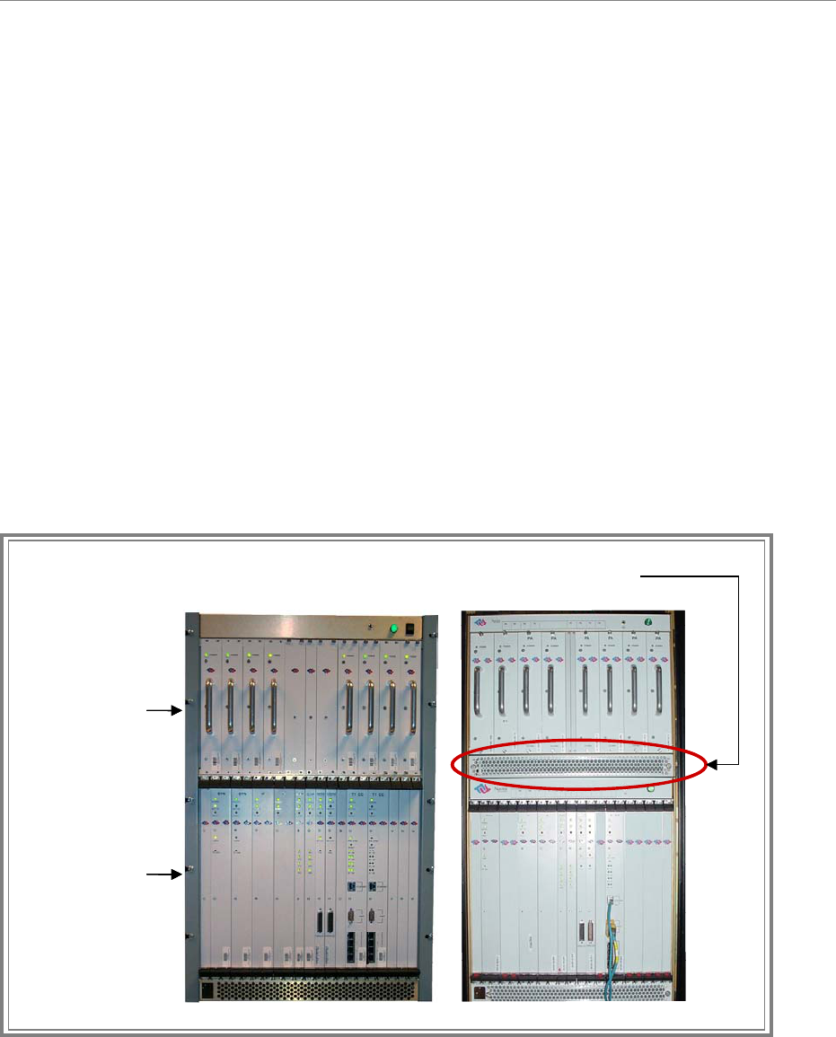
The BTS consists of the RF Power Amplifiers (PA’s), the digital circuit cards, the backplane,
and the mechanical enclosure or housing. It performs the signal processing and RF transmission
for the system. There are two types of chassis: Combo and Split. The Combo Chassis is used
primarily with 2.4 GHz systems. The Split Chasses is used for all other (2.3, 2.5, 2.6 GHz)
systems (Figure 3).
The chassis is compartmentalized into two sections - the RF shelf and the Digital shelf. The BTS
connects to the network using a 10/100 Base-T Ethernet connection or up to 8 T1 interfaces. Up
to three BTS assemblies can be installed per system, depending on the configuration.
Figure 3: BTS Chassis
RF Shelf
(Power Amplifiers)
Digital Shelf
(Circuit Cards)
Combo Chassis Split Chassis
RF Shelf
(Power Amplifiers)
Digital Shelf
(Circuit Cards)
Combo Chassis Split Chassis

Ripwave Base Station I&C Guide Navini Networks, Inc.
30 Part #40-00047-00 Rev D v1.0
February 28, 2003
Radio Frequency Subsystem (RFS)
The Radio Frequency Subsystem (RFS) is mounted on a transmission tower or building rooftop.
It transmits and receives data to and from the Ripwave Customer Premise Equipment (CPE)
using a digital beamforming transmission technique. The RFS may be either a panel antenna or
an omni antenna (Figure 4).
An RFS panel transmits in a directional mode, covering a transmit angle of 120 degrees. The
antenna can be used as a single mode antenna, or it can be used in a group of two or three
sectored antennas, covering 240 and 360 degrees respectively. Each panel requires a BTS to
operate. For example, in a tri-sectored cell with 3 panels, you would need 3 BTS’s. The omni
antenna provides omni-directional coverage of 360 degrees.
An RFS panel or omni contains eight (8) antenna elements, cavity filters, and, optionally, low
noise amplifiers (LNA). For downtilt, the omni must be situated as it comes from the factory. A
panel’s downtilt can be adjusted at the site. The higher up the antenna is placed, the more
downtilt it typically required.
Figure 4: RFS
Panel (Front) OmniPanel (Back)
Panel (Front) OmniPanel (Back)
Navini Networks, Inc. Ripwave Base Station I&C Guide
Part #40-00047-00 Rev D v1.0 31
February 28, 2003
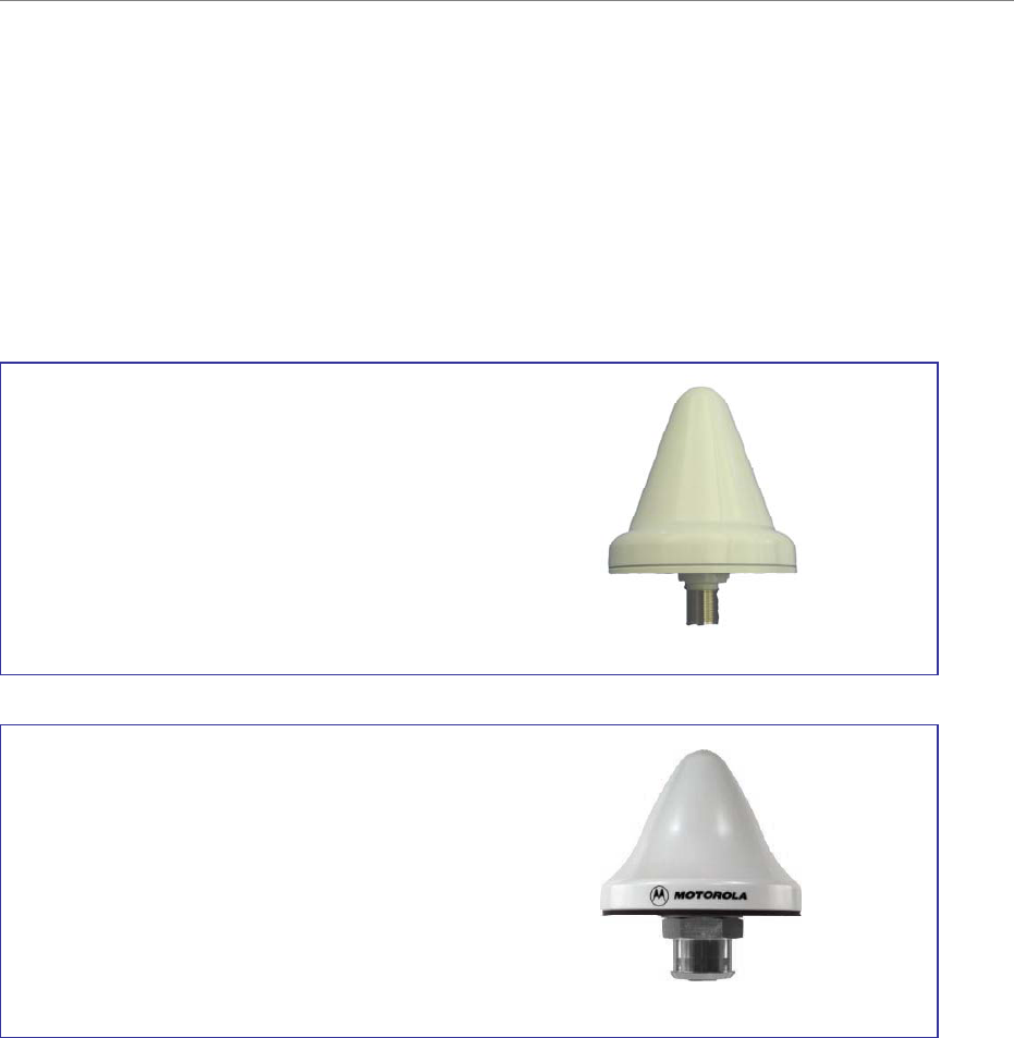
Global Positioning System (GPS)
One or two Global Positioning System (GPS) antennas are used with each Base Station. A GPS
antenna works with a constellation of satellites that orbit the earth, and it provides the ability to
pinpoint geographical locations. The two types of GPS antennas that may be ordered with a
Ripwave Base Station are the VIC 100 and the Motorola Timing 2000 (Figure 5).
Figure 5: GPS Antennas
Motorola Timing
2000 GPS
VIC 100 GPS
Motorola Timing
2000 GPS
VIC 100 GPS
Ripwave Base Station I&C Guide Navini Networks, Inc.
32 Part #40-00047-00 Rev D v1.0
February 28, 2003
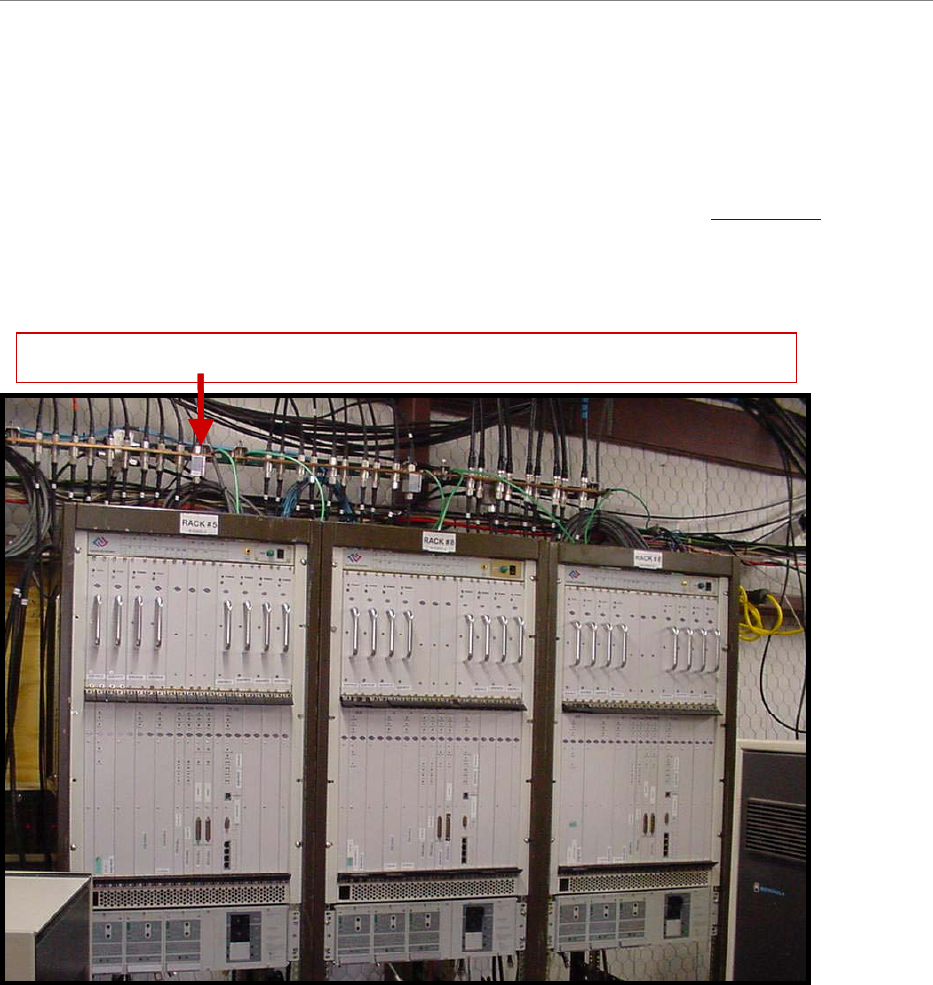
Mounting Racks & Enclosures
The BTS can be installed indoors or outdoors in industry standard 19- or 23-inch racks. Rack
adapters are needed to mount the equipment in a standard 23-inch rack. For outdoor BTS’s, the
customer can supply any standard enclosure from a multitude of vendors. Appendix J offers
suggestions for outdoor BTS enclosures. Figure 6 shows 3 BTS’s installed indoors.
Figure 6: Indoor BTS
Data/Power Cable Lightning Arrestors Across TopData/Power Cable Lightning Arrestors Across Top

Navini Networks, Inc. Ripwave Base Station I&C Guide
Part #40-00047-00 Rev D v1.0 33
February 28, 2003
General Specifications
Input Power
The BTS requires +21 to 28 VDC power supply rated at 60 amps. Installers are referred to
industry standards for power supply installations.
Humidity
The operating environment of the BTS must control relative humidity to 5% to 95% RH, non-
condensing.
Heat Dissipation
The combo BTS chassis, under normal operating conditions, will dissipate a maximum of 1000
Watts or 3415 BTU’s. The split chassis will dissipate a maximum of 1500 watts.
Airflow
Fresh air intake for the BTS chassis is along the lower front vertical panel. Exhaust is out of the
upper rear of the chassis. The I&C crew must ensure there are no obstacles to airflow present in
these areas. Exhaust air from other equipment should not mix with the BTS fresh air intake.
Accessibility
The BTS is intended for installation and use only in a restricted access location.

Ripwave Base Station I&C Guide Navini Networks, Inc.
34 Part #40-00047-00 Rev D v1.0
February 28, 2003
Base Station Specifications
Current Ripwave operating frequencies include those shown in Table 3. Testing on other
frequencies is underway and soon will be commercially available.
Table 3: Operating Frequencies
Model Frequency Range Operating Band Chassis
2.3 GHz 2.305 GHz to 2.359 GHz WCS Split
2.4 GHz 2.40 GHz - 2.473 GHz ISM Combo
2.5 GHz 2.50 GHz - 2.595 GHz MMDS/ITFS Split
2.6 GHz 2.602 GHz – 2.637 GHz MMDS/ITFS Split
The Ripwave Base Station can be in a combo chassis or split chassis system. The split chassis is
for MMDS bands only; it is not available for 2.4 GHz systems. The specifications for the combo
and split chassis are shown in Tables 4 and 5.
Table 4: Combo Chassis System (ISM Systems)
Antenna Downtilt: 2 & 4 degree options for Omni-directional; Mechanical for 120 degree
Sectored
Antenna Gain: 12dBi Omni-directional, 17 dBi for 120-degree Sectored
Antenna Options: Omni-directional or 120-degree Sectored
Backhaul Interfaces: 10/100 BaseT Ethernet or ATM over T1; up to (8) T1’s with or without
IMA, long haul support
Bandwidth Allocation: Dynamic
Baseband Modulation: Uplink QAM4
Beamforming Gain: 18dB
Configurations: Omni-directional or Sectored; Indoor or Outdoor
DC Power Consumption: 21VDC to 28VDC @ 40 amps; 1000 watts
Duplex Format: Time Division Duplexing (TDD)
Mechanical Dimensions: 30’’x19’’x14’’ for indoor BTS (single cell/sector), 60“x15”diameter for
omni RFS antenna, 46”x23” sectored RFS antenna
Multiple Access Schemes: Multi-carrier Beamforming Synchronized (MCBS) CDMA
Operational Frequency Band: See Table 3
Operational Temperature: 0 to +50 degrees C (indoor); -40 to +50 degrees C (outdoor)
Polarization: Vertical
Power Control: Forward & reverse, open & closed loop
Regulatory: UL 1950, FCC part 15
Reliability/Availability: Load-sharing
RF Channel Bandwidth: 6MHz
RF Output Power (per channel): 5 watts max
Sensitivity: -114 dBm/single channel (NF of 5dB)
Serviceability: Field replaceable cards, EMS remote reset
Spreading Spectrum Scheme: Direct Sequence Spreading (DSS)
Storage Temperature: -40 to +70 degrees C
System Features: Reed Soloman forward error correction
(
FEC
)
, con
g
estion control, automatic

Navini Networks, Inc. Ripwave Base Station I&C Guide
Part #40-00047-00 Rev D v1.0 35
February 28, 2003
repeat request (ARQ), extensive GoS/QoS mechanisms
System Throughput: 12 Mbps (fully loaded max raw data rate downstream + upstream)
Up/down Link Duplex: Symmetrical TDD
Upgradeability: Software downloads
Weight: 100 lbs (indoor BTS), 64 lbs (RFS antenna)
Table 5: Split Chassis System (MMDS & WCS Systems)
Antenna Downtilt: 2 & 4 degree options for Omni-directional; Mechanical for 120 degree
Sectored
Antenna Gain: 12dBi Omni-directional, 17 dBi for 120-degree Sectored
Antenna Options: Omni-directional or 120-degree Sectored
Backhaul Interfaces: 10/100 BaseT Ethernet or ATM over T1; up to (8) T1’s with or without
IMA, long haul support
Bandwidth Allocation: Dynamic
Baseband Modulation: Uplink QAM4
Beamforming Gain: 18dB
Configurations: RFS Omni-directional or Sectored. 1 BTS per antenna.
DC Power Consumption: 21VDC to 28VDC; 1353 Watts typical, 1500 Watts maximum
DC Power Interface: 2 - ¼” lugs for +24V DC and 24V return.
Duplex Format: Time Division Duplexing (TDD)
Humidity: 0 to 95% non-condensing
Mechanical Dimensions: Digital: H19.2” X W19.0” X D12.9” (add ~1.3” to D with modules
installed). RF: H14.0” X W19.0” XD15.2” (add ~1.5” to D with modules
installed).
Multiple Access Schemes: Multi-carrier Beamforming Synchronized (MCBS) CDMA
Operational Frequency Band: See Table 3
Operational Temperature: 0 to +50 degrees C (indoor); -40 to +50 degrees C (outdoor)
Polarization: Vertical
Power Control: Forward & reverse, open & closed loop
Regulatory: UL 1950, FCC part 15
Reliability/Availability: Load-sharing
RF Channel Bandwidth: 6MHz
RF Output Power (per channel): 5 watts max
Sensitivity: -114 dBm/single channel (NF of 5dB)
Serviceability: Field replaceable cards, EMS remote reset; Front and rear access required
Spreading Spectrum Scheme: Direct Sequence Spreading (DSS)
Storage Temperature: -40 to +70 degrees C
System Features: Reed Soloman forward error correction (FEC), congestion control, automatic
repeat request (ARQ), extensive GoS/QoS mechanisms
System Throughput: 12 Mbps (fully loaded max raw data rate downstream + upstream)
Up/down Link Duplex: Symmetrical or Asymmetrical TDD with a maximum of 3:1 ratio for
down/up allocations
Upgradeability: Software downloads
Weight: Digital Shelf 35 lbs + RF Shelf 82 lbs.

Ripwave Base Station I&C Guide Navini Networks, Inc.
36 Part #40-00047-00 Rev D v1.0
February 28, 2003
Materials Specifications
The Base Station installation requires general materials and parts for installation. In Table 6 is a
partial list of the items that may be used for a typical installation of the Ripwave Base Station. A
more complete list is provided in Appendix O. The quantity and use of materials will vary
depending on the specific installation. The lists in Table 6 and in Appendix O are based on a
150-foot site.
Table 6: Materials Specifications
Base Station General Materials Requirements List
BTS Install Kit 96-05000-00 Description Supplier Rqd Qty
GROUNDING
Lightning Rod Lightning Rod - 8' MTS
Ground Rod Tinned copper ground rod, 5/8" x 8' MTS
Ground Wire # 2 Stranded green ground wire MTS 50 Ft
Ground Wire # 6 AWG Stranded Green Wire LOCKE 50 Ft
Ground Buss Bar (Tower) Ground buss bar kit, 1/4" x 2-1/2" x 12-1/2" MTS 1 Kit
Ground Buss Bar (Shelter) Copper Gnd buss bar, 1/4" x 4", drilled to 5/8" ALT 1 Kit
Ground Lug #6, One Hole T&B 3 Pcs
Ground Lug #6, Two Hole T&B 6 Pcs
Ground Lug #2, Two Hole T&B 2 Pcs
Grounding Kit (1/2"), LMR600 STD Ground kit, LMR-600, 5' x 3/8" 2 hole lug MTS 27 Kits
Grounding Kit (3/8"), LMR400 STD Ground kit, LMR-400, 5' x 3/8" 2 hole lug MTS 2 Kits
Grounding Kit (1/2"), RF-1/2" Ground Kit, RF-1/2", 2 hole lug
N
K Cables
Universal Grounding kits Universal grounding kit, 3' with 3/8" 2 hole lug MTS
ANTENNA SYSTEM
RFS Antenna Omni Antenna
N
avini
RFS Surge Protector RFS surge protector POLYPHASER 9 Pcs
RFS Antenna Mount Omni Antenna Mount MTS 1 Kit
Weatherproofing kits Universal weatherproofing kit, Large MTS 2 Kits
RFS Antenna Power Cable RFFE Power/Data Main Cable assembly Probity 1 Kit
RFS Antenna Jumper Cable RFFE Power/Data Jumper cable, 10 Feet. Probity 1 Kit
Mounting Clamps Crossover Clamp, 1.5" x 3.5" OD MTS 1 Kit
Mounting Clamps Pipe to pipe clamps, kit of 2 MTS 1 Kit
MAIN FEEDER
RFS Cable LMR 600, 1/2" coaxial cable HUTTON/TIMES 1350 Ft
RFS Type N Male Connectors EZ600 N type, Male connectors HUTTON/TIMES 36 Pcs
Hoisting Grips Pre-laced Hoisting Grip, 1/2" MTS 10 Pcs
Cushion Hangers 1/2" Cushion hanger assembly, 5H, 1/2", kit of 5 MTS 12 kits
Cushion Hangers 3/8" Cushion hanger assembly, 6H, 3/8" for LMR400 MTS
Angle Adapter Adapter, Galvanized, Angle kit of 10 MTS
Cross Cushion Hanger Mounts Cross cushion hanger mount, kit of 5 MTS 6 Kits
Universal Hanger 1/2" Hanger, Universal, Snap-In, 1/2", kit of 10
N
K Cables
Support Blocks Mini Coax Support Blocks, kit of 10 MTS 2 Kits
RFS Connector MALE, N TYPE, 3/8 INCH
N
K Cables
RFS Connector MALE, N TYPE, 5/8 INCH
N
K Cables
RFS Connector MALE, N TYPE, 1/2 INCH
N
K Cables
RFS Connector MALE, N TYPE, 7/8 INCH
N
K Cables

Navini Networks, Inc. Ripwave Base Station I&C Guide
Part #40-00047-00 Rev D v1.0 37
February 28, 2003
RFS Connector FEMALE, N TYPE, 5/8 INCH
N
K Cables
RFS Connector FEMALE, N TYPE, 7/8 INCH
N
K Cables
RFS Connector
N
STRAIGHT PLUG, EZ PIN, FEMALE (LMR400) HUTTON/TIMES
RFS Connector
N
RIGHT ANGLE, EZ PIN, MALE (LMR400) HUTTON/TIMES
RFS Connector
N
RIGHT ANGLE, SOLDER PIN, MALE (LMR400) HUTTON/TIMES
RFS Connector
N
STRAIGHT, SOLDER PIN,MALE (LMR400) HUTTON/TIMES
Weatherproofing Sealing Compound, Coax Cable Connector
N
K Cables
RFS Cable CABLE, COAX, RF, CORRUGATED, 3/8 INCH
N
K Cables
RFS Cable CABLE, COAX, RF, CORRUGATED, 5/8 INCH
N
K Cables
RFS Cable CABLE, COAX, RF, CORRUGATED, 1/2 INCH
N
K Cables
RFS Cable CABLE, COAX, RF, CORRUGATED, 7/8 INCH
N
K Cables
GPS SYSTEM
GPS Antenna GPS Antenna, N-type Female Motorola 2 Pcs
GPS Surge Protector GPS surge protector, Redundant POLYPHASER 2 Pcs
GPS Surge Protector GPS surge protector, Non-redundant POLYPHASER 1 Pc
GPS Cable LMR400, 3/8" coaxial cable HUTTON/TIMES 200 Ft
GPS Type N Male Connectors EZ400 N type, Male connectors HUTTON/TIMES 8 Pcs
ENTRY PORT SYSTEM
Goose Neck - J type Hood entry TBD
Feed Thru Entry Panel TBD
Boot Assembly Kits Boot Assembly Kit, 4" w/ 4 holes (LMR 600) MTS 4 Kits
BTS SYSTEM
Ripwave 2400 BTS
N
avini
BTS Surge Protector BTS surge protector POLYPHASER 9 Pcs
24 VDC Power Supply Argus 1 Unit
DC Power Wire # 6 AWG, Stranded, RED Wire
DC Power Wire # 6 AWG, Stranded, BLACK Wire
BREAKER 24 VDC, 60A Distribution Breaker Argus
ROUTER CISCO 2600 Dual 10/100 ENET, WIC/NM Slots CISCO
SERIAL WAN Serial Interface WAN Card, One Port CISCO
T1-IMA MODULE Multiport T1/E1 Network Module with IMA CISCO
Air conditioning TBD
110 VAC Power Outlets TBD
Telco / Ethernet Connectors RJ45 TBD
MISCELLANEOUS
Expanding Foam Sealer TBD
Bolts (Ground) Bolt, Hex, 1/4-20 x 1.000 LG, SSPA QUESTRON
N
uts (Ground)
N
ut, Reg, Hex, Cres, 1/4-20UNC QUESTRON
Flat Washer (Ground) Wash, Flat, Cres, #6 T-B-Reg .156x.438x.040 QUESTRON
Lock Washer (Ground) Wash, Lock. Split, Cres 1/4, Reg .252x.487x.062 QUESTRON
Star Washer (Ground) Wash, Star, 1/4 QUESTRON
Star Washer (BTS Chassis Ground) Wash, Star, #10 QUESTRON
N
ut (BTS, Power/Data Surge P)
N
ut, Hex, #10-24 QUESTRON
Equipment Open Rack Rack, 19" x 72" with 1/4" x 1" holes CHATSWORTH
Tie wraps TBD
Split Bolt #2/0 TBD
Uni-Struts TBD
Anchor/Expansion Bolts TBD
Cable Ladder TBD

Ripwave Base Station I&C Guide Navini Networks, Inc.
38 Part #40-00047-00 Rev D v1.0
February 28, 2003

Navini Networks, Inc. Ripwave Base Station I&C Guide
Part #40-00047-00 Rev D v1.0 39
February 28, 2003
Chapter 2: Installation
Pre-installation
As was shown in Figure 2, prior to installation a number of planning activities take place. The
installation itself takes only about 2 days. The I&C crew usually is not involved with all the pre-
installation activities. Of these, they are likely to be most involved in the Site Candidate
Evaluation.
Project Plan
A Project Plan is a document that lays out the work to be done, the objectives of the project, the
schedule, resources required, and so forth. If Navini is performing the I&C activities, a Project
Manager is assigned. The Project Manager prepares the Project Plan and shares it with the
Navini and customer teams.
Coverage Prediction Map
Early in the planning of deployment of Ripwave Base Station equipment, an RF Engineer will go
through the process of studying the RF environment of the candidate sites that the customer has
identified. Readings are taken and analyzed at each site in order to predict what range of
coverage can be expected from installing a Base Station at the site. Coverage predictions account
for both Base Station performance as well as Marketing objectives with the service itself. The
customer accomplishes the latter as part of the decisions concerning site selection.
Site Candidate Evaluation
Often Technicians will be very comfortable with either the networking side or the wireless side
of the system, but not usually both. To evaluate a potential install site, a form is used to ensure
all aspects of the site have been considered. Information is recorded on the form. Since each site
is unique, the form helps to ensure nothing is taken for granted or assumed about the installation
site for the Ripwave equipment. A copy of this form may be found in Appendix B. It includes
places to capture the logistics of the site, tower or rooftop mount possibilities, GPS coordinates,
type of antenna to be installed, whether or not an outdoor enclosure is provided, power
availability, distance between connection points, ventilation, a place for drawings from every
angle, etc. It is from this information that the site will be designed, then installed to plan.

Ripwave Base Station I&C Guide Navini Networks, Inc.
40 Part #40-00047-00 Rev D v1.0
February 28, 2003
Interference Analysis
The RF Engineer(s) also analyzes existing interference from other sources, and takes that into
account when creating the coverage prediction map. In addition to coverage, though, the
interference analysis also helps to predict the quality of service, the power requirements to get
above the noise floor, and other expectations regarding the site. This study will help Navini and
the customer decide which type of system (frequency) and antenna (panel or omni) will provide
the best results.
Network Architecture Plan
The IP Networking community involved in the project, both from Navini and the customer, work
together to analyze and plan how the Ripwave system will be integrated into the customer’s
network. Of course, they are looking for efficient operation of the system and seamless
integration. They have to plan the traffic routing, IP addressing, protocol compatibility, and so
forth.
Bill of Materials
Someone has to generate the Bill of Materials (BoM) - the actual equipment order to be
manufactured and shipped to the installation site. Navini can provide part numbers and ordering
information, as well as recommendations and other details that will assist customers in the
correct placement of orders. There is a sample Bill of Materials in Appendix O.
Backhaul Connections
The Backhaul connections for the Ripwave Base Station consist of up to two (2) Ethernet cable
connections with RJ-45 connectors for each BTS installed, OR, up to eight (8) T1 connections
with RJ-48 connectors for each BTS. The quantity of each connection will depend on the site
requirements. These connections need to be made available before installation begins.
Power Requirements for the Base Station
The input power source will be determined during the site survey. The DC power source needs to
be an independent hard-wired circuit of 21VDC to 28VDC with a 50-amp breaker for the Combo
Chassis and a 70-amp breaker for the Split Chassis. The power plant return bus must be
connected to an earth ground connection similar to the Base Station chassis. Insulated #6 AWG
cable is recommended. The combo chassis system generates up to 1000 Watts, and the split
chassis system generates up to 1500 Watts maximum; however, 1353 Watts is typical.

Navini Networks, Inc. Ripwave Base Station I&C Guide
Part #40-00047-00 Rev D v1.0 41
February 28, 2003
Ground Requirements for the Base Station
The Base Station requires an earth ground connection. This ground should exhibit a maximum of
five ohms across true ground.
NOTE: The installation procedures, which begin next, follow the same order as shown in
the I&C Flowchart in Figure 2.
An example of a Base Station drawing for a particular site is provided in Appendix P.
An example of a written Statement of Work (SOW) and Responsibility Assignment Matrix
(RAM) for installation and commissioning are provided in Appendices Q and R. This type of
document may be used in negotiating work between companies and contractor services.
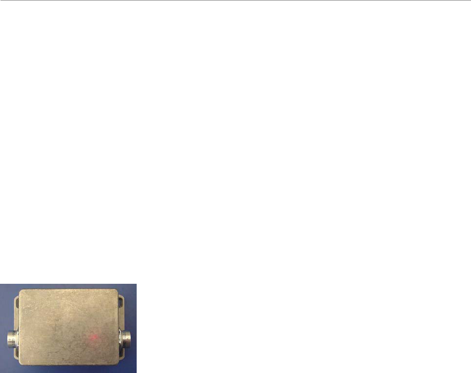
Ripwave Base Station I&C Guide Navini Networks, Inc.
42 Part #40-00047-00 Rev D v1.0
February 28, 2003
Install Power & Grounding
System Ground Buss Bar & Surge Protectors
The Base Station system ground buss bar and data/power cable surge protectors are mounted on
the wall adjacent to the BTS rack or enclosure. They should be mounted per accepted telecom
standards and procedures.
Step 1. Mount the data/power cable surge protectors (Figure 7) with the label ‘lines’ toward
the RFS and the label ‘BTS’ toward the BTS.
Step 2. Apply a thin coat of anti-oxidant joint compound to both sides of the system ground
buss bar to ensure proper connection between it and the surge protectors.
Figure 7: Data/Power Cable Surge Protector
To install the eight (8) antenna and one (1) cal cable surge protectors (Figure 8), and the one (1)
or two (2) Global Positioning System (GPS) surge protectors (Figure 9) in the system ground
buss bar, follow the steps below.
1. Install the rubber gasket into the groove in the surge protector.
2. Install the surge protector in the system ground buss bar with the surge side toward the
antenna and the protected side toward the BTS.
3. Install the star washer and nut on the top of the surge protector. Torque the nut to 140-150
inch-pounds.
4. When finished, the mounted surge protectors in the buss bar will appear as in Figure 10.
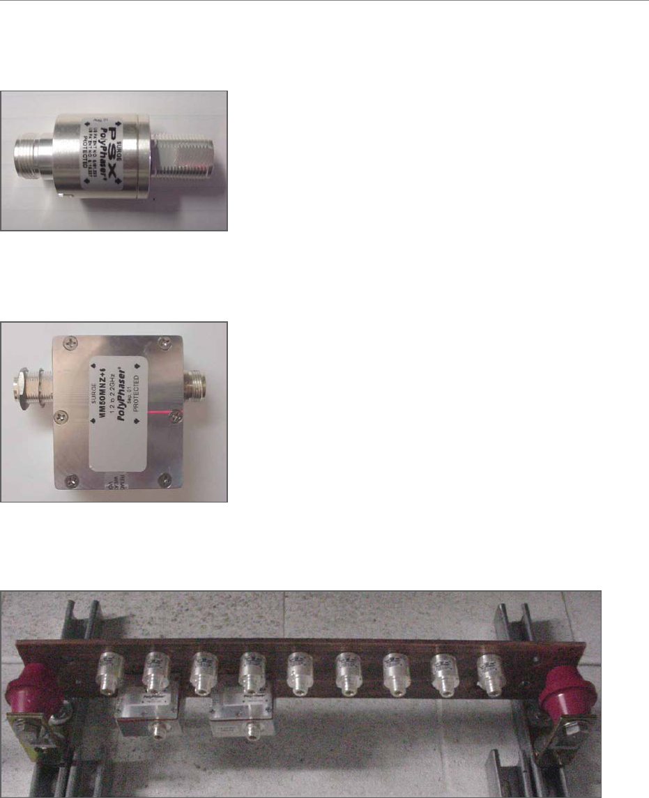
Navini Networks, Inc. Ripwave Base Station I&C Guide
Part #40-00047-00 Rev D v1.0 43
February 28, 2003
Figure 8: Antenna & Cal Cable Surge Protector
Figure 9: GPS Cable Surge Protector
Figure 10: Surge Protectors in Buss Bar
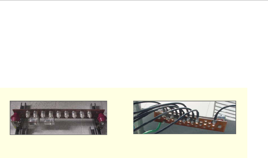
Ripwave Base Station I&C Guide Navini Networks, Inc.
44 Part #40-00047-00 Rev D v1.0
February 28, 2003
Antenna Ground Buss Bar
You should install the Antenna Ground Buss Bar on the mounting structure per accepted telecom
standards and procedures (Figure 11). The location is decided on during the site survey and
should be close to the RFS. Two or more buss bars may be installed per system.
Figure 11: Buss Bars
System Ground Wiring
A minimum #6 stranded copper, green-coated wire and grounding hardware are used for ground
connections. Install the system ground as a single-point connection between the system ground
buss bars, the data/power surge protector, the BTS chassis, the BTS mounting rack, and the RFS
antenna. Connect the system ground to earth ground. Apply anti-oxidant joint compound to all
connections. Tighten all connections until secure.
Antenna Buss BarBTS Buss Bar Antenna Buss BarBTS Buss Bar

Navini Networks, Inc. Ripwave Base Station I&C Guide
Part #40-00047-00 Rev D v1.0 45
February 28, 2003
Install Cables
All cable connections are made using standard RF coaxial cable. The Navini Networks standard
for cable connections from the GPS to the BTS is LMR 400, 3/8-inch coaxial cable. Other types
of cable that are comparable may be used. Using Tables 7 and 8, determine the size and type of
cable to be used in the installation of the Base Station.
Table 7: Active & Passive RFS Loss / Operating Parameters
PA Max
Output
Power
[dBm]
BTS Max
Output
power
with
*Filter
[dBm]
CAL
Cable
Min
Loss
CAL
Cable
Max
Loss
RF
Cable
Min
Loss
[dB]
Active
RFS
Loss
Typ
[dB]
Passive
RFS
Loss Typ
[dB]
TX
Pwr
to
Ant
Min
[dBm]
TX
Pwr
to
Ant Max
[dBm]
RX
Power
to Ant
Min
[dBm]
RX
Power
to Ant
Max
[dBm]
Notes
2.3 +38 +37 3.0 6.0 0 3.2 1.7 20 35 -95 -75
2.4 +37 N/A 4.0 9.5 0 3.2 1.7 10 25 -85 -65 -05
SYN
2.4 +37 N/A 3.0 4.5 0 3.2 1.7 18 30 -95 -70 -01
SYN
2.5 +39 +38 3.0 6.0 0 3.2 1.7 20 35 -95 -75
2.6
EF
GH
+39 +38 3.0 6.0 0 3.2 1.7 20 35 -95 -75
2.6
EF
+37 +35 3.0 4.5 0 3.2 1.7 20 35 -95 -75 -05
SYN
* Channel filter for 2.5/2.6 or Block Filter for 2.3 has 1.0 +/- 0.2 dB Insertion Loss
* Channel filter for 2.6 EF Combo is 1.8 +/- 0.2 dB including cable to backplane.
Table 8: Cable Attenuation in dB per 100 Feet
Cable Type 2 ¼″
LDF
12-50
1
5/8″
LDF
7-
50A
LMR
1700
1 ¼″
LDF
6-
50A
LMR
1200
7/8″
LDF
5-
50A
LMR
900
5/8″
LDF
4.5-
50A
½ ″
LDF
4-
50A
LMR
600
½ ″
Super
flex
FSJ
4-
50B
LMR
500
3/8″
LDF
2-
50A
LMR
400
Frequency/Size 2.350 1.980 1.670 1.550 1.200 1.090 0.870 0.865 0.630 0.590 0.520 0.500 0.440 0.405
2000 MHz 0.994 1.11 1.5 1.42 1.99 1.82 2.64 2.27 3.25 3.9 5.09 4.84 5.17 6
2400 MHz N/A 1.24 1.7 1.5 2.2 2.02 2.9 2.52 3.63 4.3 5.67 5.4 5.67 6.6
2500 MHz N/A 1.27 1.71 1.53 2.26 2.07 3 2.58 3.70 4.42 5.8 5.48 5.91 6.8
2600 MHz N/A 1.3 1.8 1.57 2.3 2.12 3.1 2.64 3.78 4.5 5.94 5.6 5.91 6.9
Weight lbs/ft 1.22 0.82 0.74 0.63 0.45 0.33 0.27 0.15 0.15 0.13 0.14 0.1 0.08 0.07
Bend Radius
inches
24 20 13.5 15 6.5 10 3 8 5 1.5 3 1.25 3.75 1

Ripwave Base Station I&C Guide Navini Networks, Inc.
46 Part #40-00047-00 Rev D v1.0
February 28, 2003
Cable Preparation
The cable run is determined during the site survey. Note that the length of the cables may need to
be slightly different, depending on the position of the buss bar relative to the BTS.
• Cut nine (9) pieces of cable for the main feeder cables to connect the nine RFS
connectors to the surge protectors on the system ground buss bar. Leave enough extra
length for the service loop below the RFS and for connection to the surge protectors.
• Cut eight (8) pieces of cable for the jumper cables to connect the surge protectors on the
system ground buss bar to the eight (8) RF input connectors on the back of the BTS.
Leave enough extra cable length for service.
• Cut one (1) piece of cable for the jumper cable to connect the surge protector on the
system ground buss bar to the CAL connector on the back of the BTS. Leave enough
extra cable length for service.
• Cut a piece of LMR 400 cable to connect each of the GPS antennas to the surge
protectors on the system ground buss bar. Leave enough extra cable length for service.
The maximum length of the LMR 400 cable for the GPS antenna is 100 feet.
• Cut a piece of LMR 400 cable to connect the surge protectors on the system ground buss
bar to each GPS connector on the back of the BTS. Leave enough extra cable length for
service. If there is more than one BTS co-located in the installation, two GPS antennas
can serve all BTS’s in the installation.
• The cable from the GPS antenna (after it goes through the surge protector) is connected
to the antenna input of the GPS distribution amplifier (Figure 12). The output ports of the
GPS distribution amplifier are connected to the GPS inputs of the BTS. The GPS
distribution amplifier is powered by the GPS antenna input. The drawing in Figure 13
depicts the placement of the shared GPS resources among three BTS’s.
Figure 12: GPS Distribution Amplifier
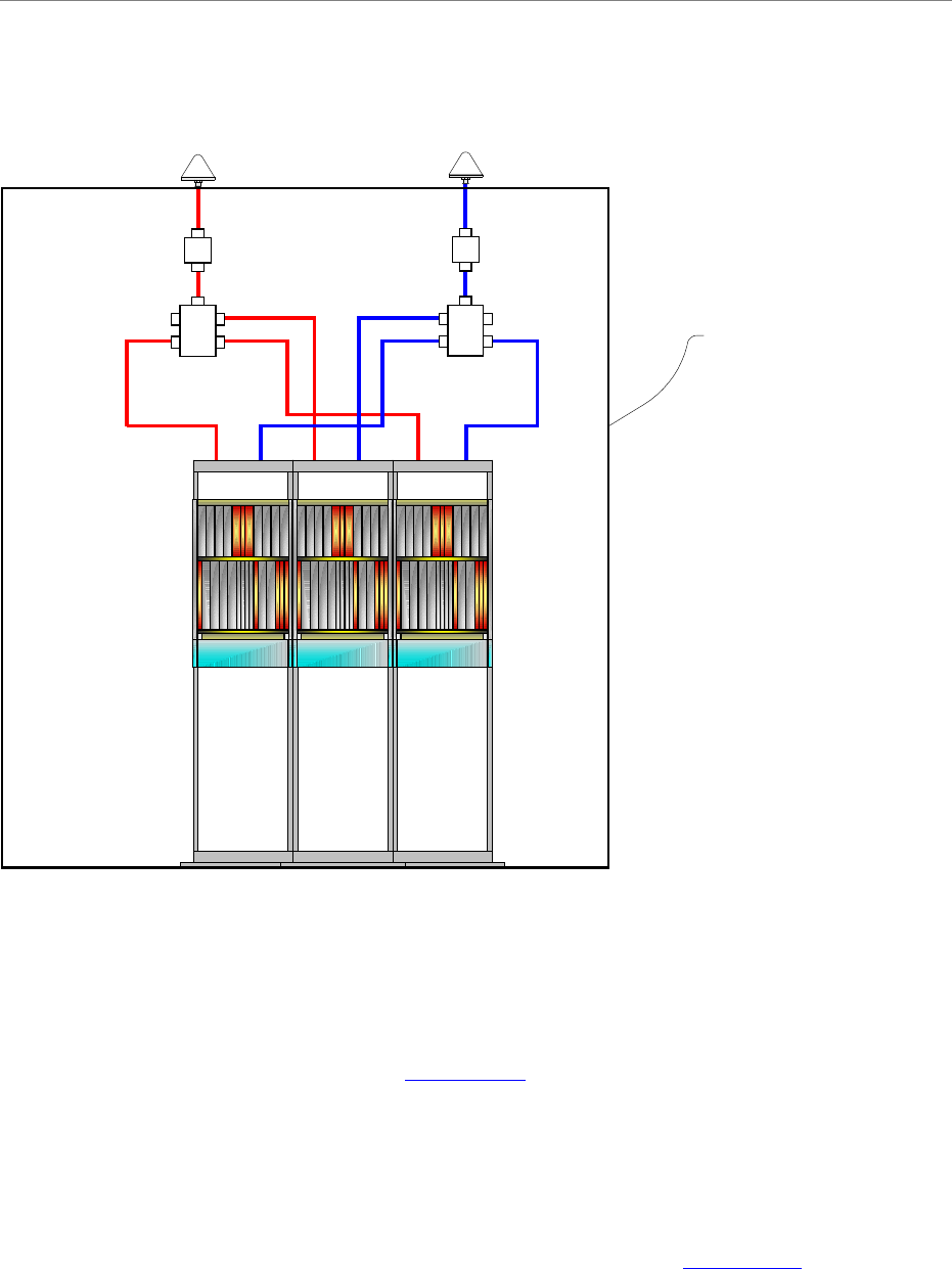
Navini Networks, Inc. Ripwave Base Station I&C Guide
Part #40-00047-00 Rev D v1.0 47
February 28, 2003
Figure 13: Depiction of GPS Distribution Amplifier
Install Connectors on Cables
Install connectors on both ends of each cable. For LMR 600 cables, install EZ-600 N-type male
connectors. For LMR 400 cables, install EZ-400 N-type male connectors. Steps for installing
both types of connectors can be found in Appendix K. For reference, Appendix L also provides a
list of vendors who can make cables.
Sweep Individual Cables
Sweep each individual cable, the RFS (8) and CAL main feeder and jumper cables, to check for
line loss. Follow the instructions for sweeping the cables provided in Appendix C, entering the
results in the RFS System Test Form. Check continuity of the data/power cable. When finished,
cover the cable connectors for protection until they are connected to the RFS or GPS.
GPS 1
Polyphaser
Distribution Amp
GPS 2
Polyphaser
Distribution Amp
BTS 1 BTS 2 BTS 3
SHELTER
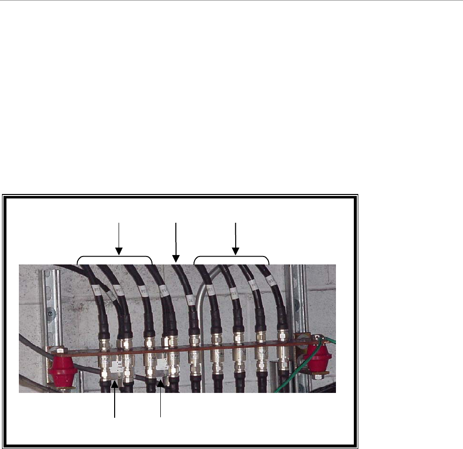
Ripwave Base Station I&C Guide Navini Networks, Inc.
48 Part #40-00047-00 Rev D v1.0
February 28, 2003
Connectorize & Run Cables
Connect all of the RF cables to the surge protectors in the system ground buss bar. An example
of a buss bar connection is shown in Figure 14. Ensure that the proper cable is connected to the
proper surge protector. Connect the power/data cable to its surge protector. Also connect all the
jumper cables to the surge protectors that will attach to the BTS. Do not connect these cables to
the BTS at this time. Torque all the cable connectors to the surge protectors on the system
ground buss bar to 20-24 inch-pounds.
Figure 14: Buss Bar Connections
Route all of the cables – RFS (8), CAL, DATA/POWER and GPS (1 or 2) - between the system
ground buss bar and the RFS, and GPS mounting sites. If running the cables up a tower, use a
hoisting grip to lift the cables (Figures 15 and 16).
RFS 1 - 4 RFS 5 - 8CAL
GPS 1 GPS 2
RFS 1 - 4 RFS 5 - 8CAL
GPS 1 GPS 2
Navini Networks, Inc. Ripwave Base Station I&C Guide
Part #40-00047-00 Rev D v1.0 49
February 28, 2003
Figure 15 : Omni Cable Routing
Figure 16: Panel Cable Routing
Calibration CableCalibration Cable RF CablesRF Cables
Data/Power CableData/Power Cable
Data/Power
Cable
Calibration Cable
RF Cables
Data/Power
Cable
Calibration Cable
RF Cables
Ripwave Base Station I&C Guide Navini Networks, Inc.
50 Part #40-00047-00 Rev D v1.0
February 28, 2003
Install the BTS
Install Mounting Rack or Enclosure
The BTS mounting rack (Figure 17) or enclosure is to be installed in compliance with applicable
portions of the National Electrical Code (NEC), articles 800 and 810. You will need to adhere to
local installation standards, as well as Navini Networks standards and procedures. Refer to
Appendix J for guidelines on outdoor BTS enclosures.
Figure 17: BTS Mounting Rack