Cisco Systems BTS-R3 Broadband Data BTS User Manual chpt 2b 40 00047 03 F I C TTA
Cisco Systems, Inc Broadband Data BTS chpt 2b 40 00047 03 F I C TTA
Contents
Manual 3
Navini Networks, Inc. Ripwave Base Station I&C Guide
Chapter 2b
Part #40-00047-03 Rev F v1.0 (TTA) 55
October 23, 2003
Install the BTS
Check all regulatory standards (refer to Chapter 1, Page 8 “Regulatory Information”) prior to
installation.
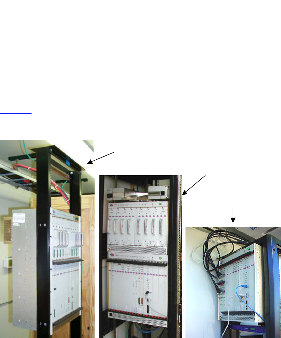
Install Mounting Rack or Enclosure
The BTS mounting rack (Figure 22) or enclosure is to be installed in compliance with applicable
portions of the National Electrical Code (NEC), articles 800 and 810. You will need to adhere to
local installation standards, as well as Navini Networks standards and procedures. Refer to
Appendix I for manufacturers of outdoor BTS enclosures.
Figure 22: BTS Mounting Racks
Combo Chassis
Split Chassis
TTA Chassis
Combo Chassis
Split Chassis
TTA Chassis
Ripwave Base Station I&C Guide Navini Networks, Inc.
Chapter 2b
56 Part #40-00047-03 Rev F v1.0 (TTA)
October 23, 2003
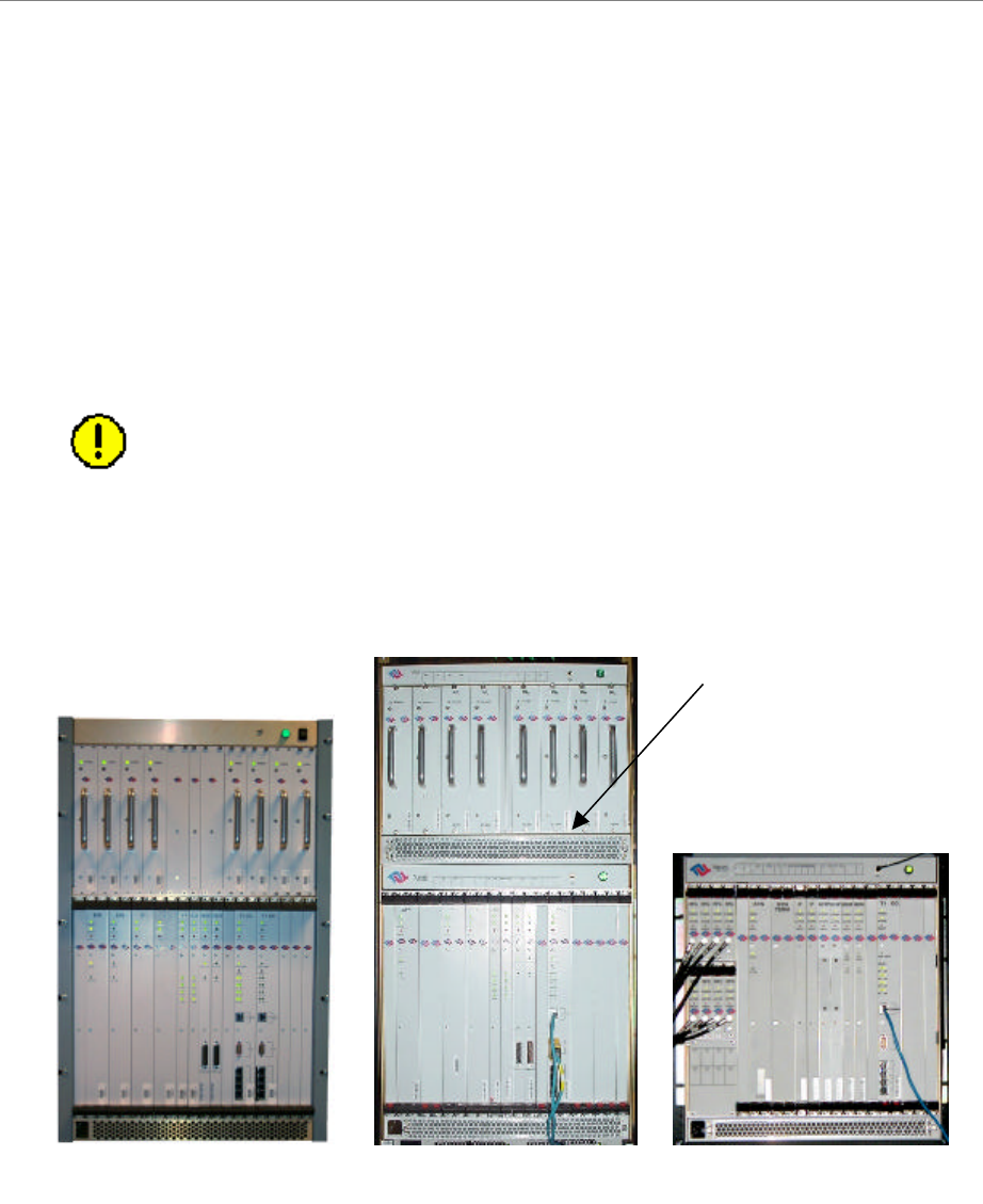
Install Chassis
There are three types of BTS chassis: Combo, Split and TTA (Figure 23). Prior to Ripwave
Release 1.19 (2.4 GHz systems), only the Combo Chassis was used, but with the licensed bands
(2.3, 2.5, and 2.6 GHz systems) it is allowed to transmit at higher levels of power, which
required better air circulation. This resulted in the introduction of the Split Chassis.
The recently introduced Tower Top Antenna (TTA) chassis, consists only of a digital shelf
because the PAs are incorporated into the base of the RFS. Notice that the TTA digital shelf
includes 8 new additional cards called RF Controllers or RFC.
CAUTION! - Please contact Navini Technical support before attempting to
exchange cards between chassis of different type and frequency to verify
compatibility.
Figure 23: BTS Chassis
Combo Chassis
Split Chassis
TTA Chassis
RF/PA ShelfDigital Shelf
(Panel separates
RF and Digital
Shelves)
(PAs are in the RFS)
Combo Chassis
Split Chassis
TTA Chassis
RF/PA ShelfDigital Shelf
(Panel separates
RF and Digital
Shelves)
(PAs are in the RFS)
Navini Networks, Inc. Ripwave Base Station I&C Guide
Chapter 2b
Part #40-00047-03 Rev F v1.0 (TTA) 57
October 23, 2003
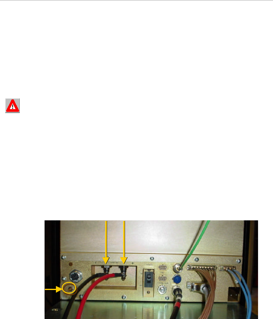
Connect Input Power
Next, connect the power supply to the BTS card cage (Figure 24). The gauge of the wire is
determined by the length of the run and by NEC/CEC standards (refer to Chapter 1, Page 8
“Regulatory Information”). Use a 60-amp circuit breaker when running the line. Terminate both
of the input power wires and the ground wire with a ¼- inch terminal lug. Assuming a +24 VDC
power supply, connect the +24 VDC input power connections and the +24 VDC return wires to
the BTS card cage.
WARNING! Ensure that the power is off before connecting the input power wires to the
BTS input terminals.
If the input power is 120 VAC, plug the two power-supply input cables into 120 VAC outlets,
and turn on the circuit breaker on the power supply. If the input power is 24 VDC, check for +24
VDC across the input terminals of the BTS card cage. If +24 VDC is not present across the input
terminals, check all input power wiring for proper connections. Also, check the power supply for
proper operation and the fuses for continuity.
When finished, turn off the power supply.
Figure 24: Split Chassis Power Connections
BTS +24 VDC Input Terminals
Ground Lug
BTS +24 VDC Input Terminals
Ground Lug
Ripwave Base Station I&C Guide Navini Networks, Inc.
Chapter 2b
58 Part #40-00047-03 Rev F v1.0 (TTA)
October 23, 2003
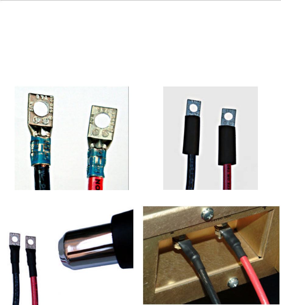
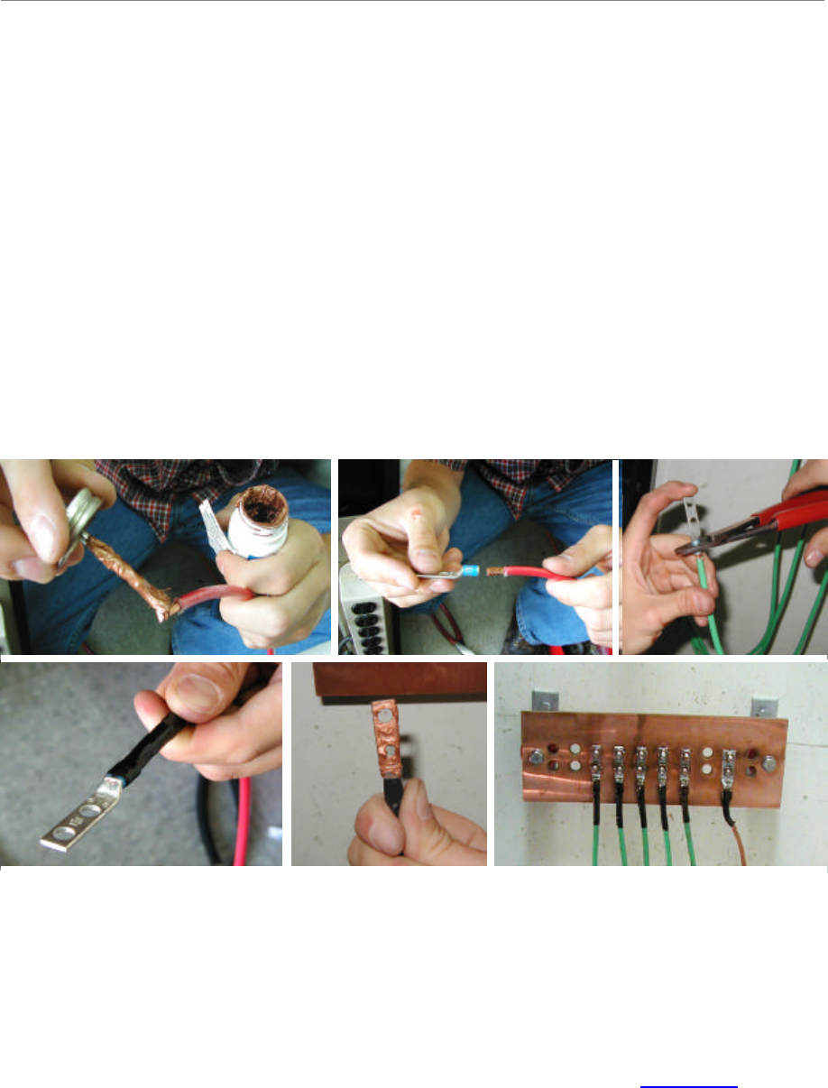
Power-interconnect wires between the power supply/rectifier and the digital chassis must have
heat shrink tubing applied over the barrel of the terminal lugs after crimping the wire. Refer to
Figure 25 below.
Figure 25: Power-Interconnect Wires
1. Install UL-Listed Terminals 2. Slide on heat-shrink tubing
3. Apply heat to shrink tubing 4. Install power cables
1. Install UL-Listed Terminals 2. Slide on heat-shrink tubing
3. Apply heat to shrink tubing 4. Install power cables
Navini Networks, Inc. Ripwave Base Station I&C Guide
Chapter 2b
Part #40-00047-03 Rev F v1.0 (TTA) 59
October 23, 2003
Connect BTS to Ground Connections
All connections need to be checked before power is applied to the system. At a minimum,
perform the following:
?? Ensure continuity across all ground connections.
?? Ensure an open connection from the power supply output (positive input to the BTS card
cage) to frame ground.
Check all regulatory standards (Chapter 1, Page 8 “Regulatory Information”) related to power
and grounding. All power and ground conductors must be mechanically supported to avoid strain
of the wires and connection points.
Figure 26: Preparing Power and Grounding Connector Tips
Connect Chassis Alarms
The chassis contains two connectors that are used to send alarm indications to the BTS when the
BTS is housed in an outdoor enclosure. One of the connectors, labeled “CABINET ALARM”, is
used to trigger alarm conditions that occur within the external chassis. The second connector,
labeled “BBU”, is used to process alarms from a battery backup unit. Refer to Appendix P for
instructions on connecting the alarms.
Ripwave Base Station I&C Guide Navini Networks, Inc.
Chapter 2b
60 Part #40-00047-03 Rev F v1.0 (TTA)
October 23, 2003
Install GPS Antennas
Check all regulatory standards (refer to Chapter 1, Page 8 “Regulatory Information”) prior to
installation.
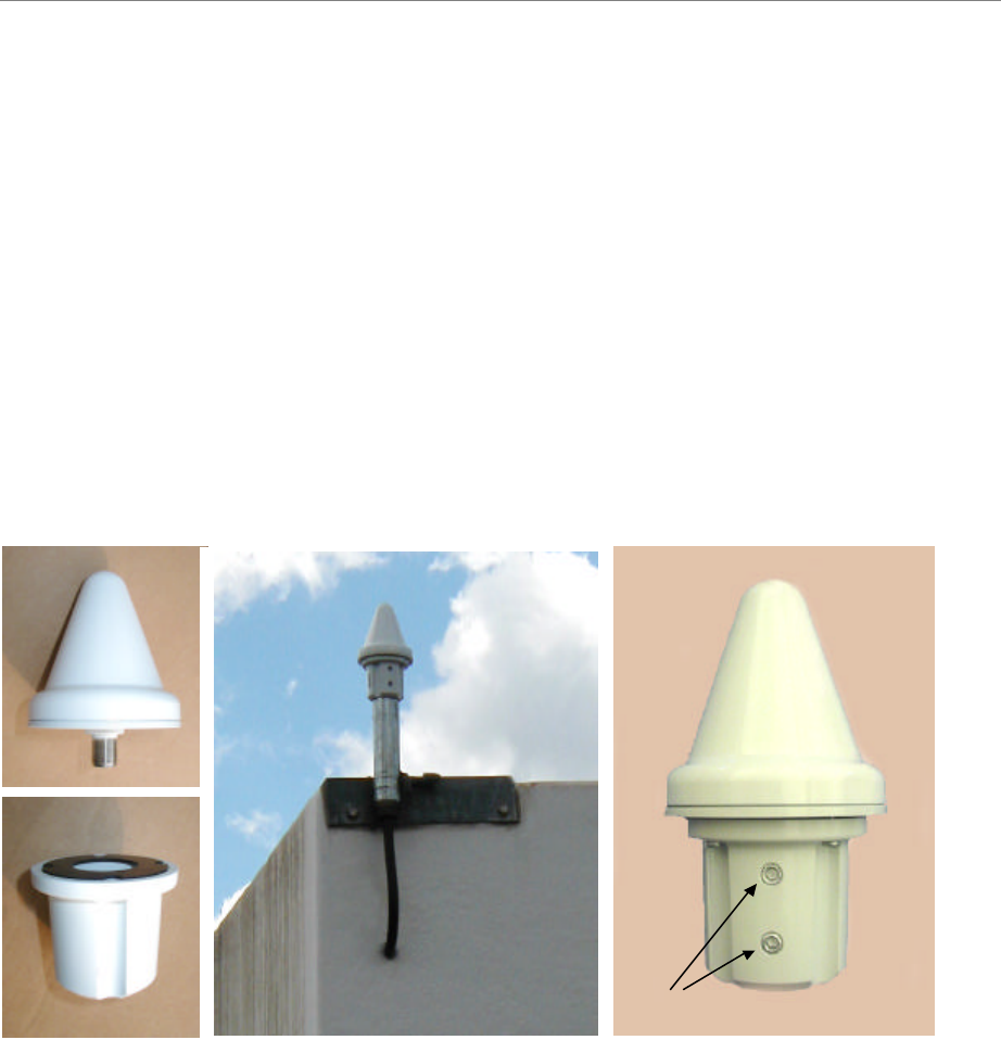
As mentioned earlier, the model of GPS antenna used with the Ripwave Base Station is the VIC
100, as shown in Figure 27.
Mount each GPS antenna module, run the cable through the pipe clamp mount. Connect the
cable to the GPS antenna, then, weatherize the connection. Secure the antenna module to the
pipe clamp mount using the captive mounting hardware. Install the GPS antenna module and the
pipe clamp mount to the mounting pipe and tighten the two mounting screws.
Figure 27: VIC 100 GPS
The mounting location for the GPS antenna is determined during the site survey. When
installing, ensure that the following requirements are met:
?? The GPS antenna is installed within 100 feet of the BTS.
?? The GPS antenna is located to provide the widest view of the sky (objects such as
buildings or trees can interfere with signals from the satellite).
Mounting Screws
Antenna
Mounting Hardware Mounting Screws
Antenna
Mounting Hardware