Cisco Systems BTS-R3 Broadband Data BTS User Manual Appendix Pt 1 40 00047 08 F I C TTA
Cisco Systems, Inc Broadband Data BTS Appendix Pt 1 40 00047 08 F I C TTA
Contents
Manual app 1

Navini Networks, Inc. Ripwave Base Station I&C Guide
Part #40-00047-00 Rev F v1.0 (TTA) 109
October 23, 2003
Appendix A: Sample Statement of Work (SoW)
The following is an example of a Statement of Work. The Statement of Work outlines the general
activities that must be conducted in order to complete the installation and commissioning tasks for a
Ripwave Base Station.
Example:
Statement of Work for Standard Installation Services
The following statement of work will be used to outline the areas of responsibilities for the Navini
Networks antenna (known as the RFS) and Base Station (known as the BTS) installations to be
completed with Navini Networks Client (referred to as Client in this document). Client may choose
to hire a contractor or tower crew to assist with its activities. Navini Networks has no formal
contract relationship with the contractor, who will be managed by Client. The following work items
are suggested content only - - final scope and terms to be negotiated directly with Client. Navini
Networks support personnel will be on site for the entire installation and commissioning process,
and will provide technical expertise, information, and recommendations with respect to site design
and installation.
It is recommended that contractor have a Non-Disclosure Agreement (NDA) in place with Client and
Navini Networks prior to execution of work. Contractor shall not publicly disclose any information
concerning this deployment or trial with any other parties, unless approved in writing in advance by
Client and Navini Networks.
Navini Networks
1. Provide Field Engineer to consult with Client and Contractor for planning efforts. Review
Site design sketches and BOM prepared by others.
2. Review network architecture information (connection diagram and logical addresses) prior to
start of installation.
3. Review Sweep results with Client and contractor. Sweep to be provided of RFS after
shipment, of coax cables and RF path on tower, and of cables and RFS after installation,
before power up.
4. Review AC and DC power system installation. Review DC power system test with Client
and contractor.
5. Review backhaul circuit installation test results with Client.
6. Review GPS antenna and cable installations.
7. Review and Verify Cable and Antenna System Installation Work
8. Site walk with contractor and Client for Punchlist.
9. Load EMS software on Client supplied workstation, and verify connectivity to BTS.

Ripwave Base Station I&C Guide Navini Networks, Inc.
110 Part #40-00047-00 Rev F v1.0 (TTA)
October 23, 2003
10. Provide BTS installation – Chassis and Cards.
11. Apply power to BTS and perform all power up, BTS calibration verification checks,
commissioning and initial testing of Navini Networks system. May use EMS on local laptop.
12. With assistance of Client, Perform Drive Test / Coverage Verification.
13. With assistance of Client, perform data rate testing at mutually specified locations – 15 for
Omni, 5 for each panel RFS.
14. With client, integrate BTS into backhaul network and verify operation.
15. Closeout / Customer Acceptance package, including inventory of hardware.
16. Navini Networks to provide own tools and test equipment.
17. Clean job site daily.
Client / Contractor Work Items
1. Perform Site survey at each site.
2. Prepare Installation sketch and Bill of Materials (BOM) for each site. Note that these are not
sealed construction drawings.
3. Client / Contractor Site Design and Bid Walk.
4. Material Procurement.
5. Acquire building permits.
6. Inside Network cabling from demark to BTS rack
7. AC power installation (provide dedicated 115 VAC 20 A circuit for each BTS, dual outlet
receptacle).
8. Air conditioning work or other hut electrical work.
9. 24 VDC rectifier installation, cabling to BTS chassis, cabling to AC circuit breaker. Test 24
VDC system (note: do not apply power to BTS).
10. Mount 19” TELCO rack inside hut (base anchors, or overhead brackets or both)
11. Provide core drilling and furnish and install feed through panel for coax cables, unless
already existing. Seal holes using similar materials to other existing feed-through at each
site.
12. Install grounding inside hut for rack and 24 VDC system. Install ground bus bar inside hut
entry per drawings. Install ground bus bars on antenna structure and ground coax cables per
sketch.
13. Install and apply coax cables and connectors. This includes main coax runs on tower, plus
coax jumpers at antenna and at hut, as specified by drawings. Recommend and Install all
cable hangers and supports, and grounding, per standard practice in use at tower location.
Install surge protectors per design sketches and BOM.
14. Sweep test coax cables at designated sweep frequencies.
15. Install power and data cable from antenna to BTS.
16. Weather seal all outside connections.
17. Recommend, furnish and install mounting structure (arm assembly) to stand-off Navini RFS
from tower. Standoff assembly to include pipe mount for antenna mount. Install Navini RFS
on arm on tower. Connect to coax cables and provide sweep of cable / RFS assembly.
Provide photographic documentation of tower top installation work.
18. Provide equipment and cable labeling as required.
19. Install (2) GPS antennas on ice bridge (or other agreed upon location). Furnish and install
any required brackets or pipe mounts. Install GPS coax cables and connectors from GPS

Navini Networks, Inc. Ripwave Base Station I&C Guide
Part #40-00047-00 Rev F v1.0 (TTA) 111
October 23, 2003
antenna to BTS.
20. Site walk at completion with Client and Navini, create Punchlist; clear applicable punchlist
items.
21. Arrange disposal of trash
22. Provide RF coverage analysis plots before start of installation. Provide model tuning, if
required.
23. Provide architecture document before start of installation, including connection diagram and
logical network element assignments (IP addresses, PVCs, etc.).
24. Set Up and Verify all network equipment and backhaul circuits.
25. Set Up and Verify Operation and connectivity of EMS computer.
26. Provide one resource to assist with drive testing and location data rate testing.
27. Provide all end user / CPE provisioning in EMS after initial testing.
28. Provide all end user interface and troubleshooting.
29. Monitor EMS / alarms. Forward trouble issues to Navini call center.
30. Contractor and Client to provide own tools, computers, and test equipment.

Ripwave Base Station I&C Guide Navini Networks, Inc.
112 Part #40-00047-00 Rev F v1.0 (TTA)
October 23, 2003

Navini Networks, Inc. Ripwave Base Station I&C Guide
Part #40-00047-00 Rev F v1.0 (TTA) 113
October 23, 2003
Appendix B: Sample Responsibility Assignment Matrix
(RAM)
The following is an example of a Responsibility Assignment Matrix (RAM). The RAM is a tool for
capturing who will do what to get systems deployed and turned up. It provides an easy-to-read and
follow tabular format. Each of the activities in the list must be addressed in order to complete the
installation and commissioning tasks for a Ripwave Base Station.
1 = Primary Responsibility S = Supply
2 = Secondary Responsibility I = Install
Item #
Task / Activity Navini Client Other Notes
MARKET PLANNING and RF ENGINEERING
1 Develop coverage objectives 1
2 Provide Hardware Specifications 1
3 Provide Link Budget 1
4 Prepare Preliminary Coverage Plots 2 1
5 Interference Analysis / Noise Floor 2 1
6 Link Specific Channel Assignments 2 1
7 Review / Approve RF Design 2 1
8 SCT Filing fees 1
9 SCT licensing / clearing 1
10 Contract RF consulting engineering 1
11 Obtain SCT Test Permit 1
NETWORK ENGINEERING & BACKHAUL
1 Network Requirements 2 1
2 Network Architecture 2 1
3 Provisioning Guidelines 1

Ripwave Base Station I&C Guide Navini Networks, Inc.
114 Part #40-00047-00 Rev F v1.0 (TTA)
October 23, 2003
Item #
Task / Activity Navini Client Other Notes
4 IP / data Address Assignment / management 1
5 Review / Approve Network Design 2 1
6 Network Architecture – backhaul 1
7 ATM layer Provisioning / management 1
8 Order Circuits 1
9 Order equipment for backhaul / interface 1
10 Backhaul Network Test 1
SITE ACQUISITION
1 Identify BTS candidates in search ring 1
2 Identify CPE Candidates per ring 1
3 Identification of Zoning requirements 1
4 Select BTS sites 1
5 Negotiate and close lease 1
6 Pay lease costs 1
7 Obtain any building permits if required 1
8 Arrange Site Access 1
SITE DESIGN
1 Site Survey – BTS sites 2 1
2 Prepare Site Design Sketches / Layout 2 1
3 Prepare BOM 2 1
4 Review Design / Approve 2 1
5 A&E Selection and management 1
6 Prepare / approve A&E drawings 1
7 Tower Structural Analysis 1
8 Contractor Qualifications and Selection 1

Navini Networks, Inc. Ripwave Base Station I&C Guide
Part #40-00047-00 Rev F v1.0 (TTA) 115
October 23, 2003
Item #
Task / Activity Navini Client Other Notes
9 Contractor walk through 1
10 Obtain / Review bids / Award contract 1
11 Obtain Building permits or other approvals 1
LOGISTICS / SHIPPING / DELIVERY
1 Create Logistics Plan 2 1
2 Ship Navini supplied Equipment to designated
warehouse 1
3 Deliver Equipment to Specific Sites 1
4 Disposal of Shipping materials 2 1
CONSTRUCTION / INSTALLATION
1 Antenna Mounts / brackets S, I
2 Antennas (Navini RFS) S I Navini will assist and
supervise installation
from the ground.
3 Coax Cable / Connectors S, I
4 Power / Signal Cable / Connectors (BTS to
RFS) S I 1 per BTS.
5 Ground Kits S, I
6 Surge protectors/Ground Buss Bars
S, I
Navini to supply surge
protector for the power
and data cable. Client to
supply surge protectors
for coaxial feedlines.
7 GPS 4-Way Splitters for multiple BTS’ installed
at one site. S, I 2 4-Way Splitters
needed for 3-sector
installation.
8 BTS Equipment Racks / Enclosures S, I Need to confirm indoor
installation. Enclosure
not required indoors.
9 DC Power System 24VDC @ 60 Amps for each
BTS S, I
10 Batteries / UPS S, I

Ripwave Base Station I&C Guide Navini Networks, Inc.
116 Part #40-00047-00 Rev F v1.0 (TTA)
October 23, 2003
Item #
Task / Activity Navini Client Other Notes
11 Intra – rack cabling S, I
12 Electrical Circuits S, I
13 Electrical – wiring from panel to rack S, I
14 Electrical (conduit, distribution panels, etc.) S, I
15 Environmental Equipment S, I
16 Miscellaneous Hardware S
17 BTS cages / cards S, I
18 Network Router S, I
19 Network Ethernet Switch with ATM interface S, I
20 EMS Server / workstation S, I
21 EMS client workstation (for techs) S, I
22 EMS client workstation (for Navini) S, I
23 Server for DHCP and network applications S, I
24 CPE S
25 User PC with Ethernet and/or USB Card S
26 Provide Construction Supervisor 2 1 Navini will supervise
installation of Navini
equipment.
27 Provide Installation Resources
2 1
Client contractors.
Navini will install the
BTS in the client
installed rack/cabinet.
Navini will provide
technical guidance for
installation of the RFS.
CONSTRUCTION
1 Site Preparation / Infrastructure 2 1
2 Pull Cables 1
3 Install Connectors and Grounding 1

Navini Networks, Inc. Ripwave Base Station I&C Guide
Part #40-00047-00 Rev F v1.0 (TTA) 117
October 23, 2003
Item #
Task / Activity Navini Client Other Notes
4 Install Surge Protectors 2 1
5 Test / Sweep Coax 2 1
6 Install mounts / brackets 2 1
7 Install Racks 2 1
8 Electrical power to Rack 1
9 Backhaul to rack 1
10 Environmental (if required) 1
11 Quality Assurance 2 1
12 Inspections / Punch List 2 1
13 Close all Punch List Items 2 1
14 Provide POTS line for technician use 1
EQUIPMENT COMMISSIONING & INTEGRATION
1 Inspect / Test Cabling / Connections 2 1
2 Install Rack Mount Power System / Card Cages 1 2
3 Test DC System 2 1
4 Plug cards in BTS 1
5 Load EMS / Configure 1
6 Boot BTS 1
7 Provision EMS / BTS / CPE 1
8 Test Operation 1
9 Integrate Backhaul 2 1
10 Verify Operation 2 1
11 Router: Configure / test 1
12 DHCP Server: configure / test 1
13 EMS Client: Configure / Test 1 2

Ripwave Base Station I&C Guide Navini Networks, Inc.
118 Part #40-00047-00 Rev F v1.0 (TTA)
October 23, 2003
Item #
Task / Activity Navini Client Other Notes
14 Configure monitoring for routers 1
TESTING
1 Determine Network Test Criteria 2 1 Based on trial
agreement.
2 Determine RF Test Criteria 1 1 Based on trial
agreement.
3 Generate Acceptance Test Plan (ATP) 1 1
4 Review Test Plan 1 1
5 Supply Test Equipment
HP/Agilent E4402B Spectrum Analyzer with
Floppy Storage Option, HP/Agilent 8648C RF
Signal Generator, Tektronix TDS 3012B Scope
1 2 Some tests will utilize
built in test capability.
6 Execute Trial Test Plan and capture data 2 1
7 Provide Vehicle and Driver for System Drive
Testing 1
8 Analyze test data and write report 2 1
9 Review Report, Trial test results 1 1
END USER ENGAGEMENT
1 Prepare End User profile 1
2 Develop User Procedures 1
3 Recruit and Sign Up Users 1
4 Distribute CPE kits 1
5 Develop User Surveys 1
6 Survey Users, collect data 1
7 Issue reports 1
SUPPORT & SERVICES
1 System Training for Service Provider 1
2 Monitor Network 2 1

Navini Networks, Inc. Ripwave Base Station I&C Guide
Part #40-00047-00 Rev F v1.0 (TTA) 119
October 23, 2003
Item #
Task / Activity Navini Client Other Notes
3 End User Contact (answer phones) 1
4 Fault Determination and Isolation 2 1 Client to provide Level
1 support.
5 Performance Reporting 2 1
6 Field Repairs / Replacements (if needed) 1 2
7 Shipping for Repairs / Replacements 2 1
8 Spares 1 Spares count TBD.
9 Install Hardware Upgrades (if needed) 2 1
10 Install Software Upgrades (if needed) 2 1

Ripwave Base Station I&C Guide Navini Networks, Inc.
120 Part #40-00047-00 Rev F v1.0 (TTA)
October 23, 2003

Navini Networks, Inc. Ripwave Base Station I&C Guide
Part #40-00047-00 Rev F v1.0 (TTA) 121
October 23, 2003
Appendix C: Sample Work Breakdown Structure (WBS)
Continued on next page.....
Site Deployment Work Breakdown
Activity
Customer 3rd Party
In-House Contractor
1System Design Criteria Established
1.1 RF Design Requirements Established
1.2 Site Configuration / BTS & RFS Requirements Established
1.3 Backhaul / T1 Requirements Established
1.4 Customer NOC / Operations Requirements Established
1.5 Network Design Requirements Established
1.6 Software Requirements Established
1.7 Hardware Requirements Established
2Site Selection Process
2.1 Candidate Identification / Site Selection
2.2 RF Propagation / Coverage Analysis
2.3 Interference Analysis / Intermod Study
2.4 Drive Test / Coverage Verification
2.5 Site Survey / Constructability Review
2.6 Zoning Analysis
2.7 FAA / FCC / ASAC Compliance Reviews / Submittals
3Site Acquisition and Leasing
3.1 Master License Agreements
3.2 Site License Agreements
3.3 Lease and Exhibit B Development Work
3.4 Rents and Payments
3.5 Entry and Testing Agreements
3.6 Phase 1 Environmental Screen
3.7 NEPA Checklist
3.8 State Historical Preservation Organization Review
4Site Design and Development
4.1 Design Coordination / Site Design Walks
4.2 A&E Drawing Package Development
4.3 Site Survey - 2C
4.4 Soils Report
4.5 Tower / Foundation Design
4.6 Structural Analysis
4.7 Permit and Const Drawing Package Review and Approval
4.8 Zoning Permits
4.9 Construction Permits - Building & Electrical
Navini Networks
Responsibility
Item No.
5Material Procurement
5.1 Bill Of Materials From Approved Construction Drawings
5.2 Vendor Selection
5.3 Bids / Quotes
5.4 Requisitions / Purchase Orders
5.5 Tower, Mounts, Lightning Protection, Lighting, Cable Ladder, Safety Climb,.
5.6 BTS - with Rack (IBTS), with Enclosure (OBTS)
5.7 RFS - Active, Passive
5.8 Cables, Connectors, Mounting Hardware, Surge Protection
5.9 AC Power Equipment
5.10 DC Power Equipment
5.11 Telco Equipment
5.12 Grounding Equipment and Materials
5.13 Delivery Coordination / Warehousing / Logistics
6Facilities Orders
6.1 Electric Power Service Order Site Walk / Engineering
6.2 Electric Power Service / Equipment Order
6.3 Telephone Service Order Site Walk / Engineering
6.4 Telco Service / Equipment Order

Ripwave Base Station I&C Guide Navini Networks, Inc.
122 Part #40-00047-00 Rev F v1.0 (TTA)
October 23, 2003
7Site / System Construction
7.1 Vendor Selection
7.2 Bids / Quotes
7.3 Requisitions / Purchase Orders
7.4 Pre-Construction Walkthrough
7.5 Site Preperation Work - Clear, Grub, Foundation Work
7.6 Tower Delivery and Offload
7.7 Tower Installation
7.8 OBTS / Shelter Delivery and Installation
7.9 Site Materials Delivery and Offload
7.10 Power Equipment Installation
7.11 Telco Equipment Installation
7.12 Grounding System Installation
7.13 Grounding System Test and Verification X
7.14 Fencing and Security System Installation
7.15 Site Finish Work - Fencing, Landscaping,…
7.16 Punchlist Construction Work
7.17 Closeout / Customer Acceptance - Site Construction
8Equipment Installation Work
8.1 Material Delivery to Site
8.2 Install RFS(s)
8.3 Install Antenna System - Cable, Supports, Surge and Grounding Protection
8.4 Test and Verify Cable and Antenna System Installation Work X
8.5 IBTS Installation - Shelves, Cards, Power, Grounding…
8.6 AC Power Equipment Installation and Testing
8.7 DC Power Equipment Installation and Testing
8.8 Telco / T1 Equipment Installation and Testing
8.9 BTS Testing
8.10 EMS / Customer Operations Equipment Installation
8.11 Punchlist Installation Work
8.12 Closeout / Customer Acceptance - Equipment Installation Work
9System Testing / Optimization
10
Customer Acceptance / Turnover
Navini Networks, Inc. Ripwave Base Station I&C Guide
Part #40-00047-00 Rev F v1.0 (TTA) 123
October 23, 2003
Appendix D: Site Candidate Evaluation Form
NAVINI NETWORKS
SITE EVALUATION FORM
PN - 40-00091-00
Site Name
Date
FSE
COMPANY NAME
ADDRESS
SITE OWNER
SITE CONTACT NO.
GPS COORDINATES LAT LONG
ANT TYPE (OMNI, PANEL)
ENCLOSURE TYPE (HUT, ETC) ELEV (AMSL) FEET
TOWER TYPE (SS, MP,ETC) HEIGHT (AGL) FEET
SITE ACCESS RESTRICTIONS OTHER
DRIVE TO DIRECTIONS
BTS Space Availability (3' x 3') x
Room for Expansion BTS x
Type/Size of Cabinet required FEET
110VAC, 20A Available/Distance FEET
AC Outlet Available/Distance FEET
24VDC, 60A Available/Distance FEET
Breaker(s) Required
Sub-metering Required
Ground Available/Distance FEET
Gnd Buss Bar Available/Distance FEET
Cable Entry Available
Cable Routing Distance FEET
Kind of Entry Material
Kind of Sealing Required
Site Plans Available
Cable Tray Available
Cable Hangers Required
Floor/Wall Drilling Permitted
Airconditioning Available
Telco/LAN/WAN Available
Demarc Location/Distance FEET
Room has Adequate Lighting
Room has Adequate Ventilation
Any Door Entry Restrictions DOOR DIMENSION
Enclosure Access OTHER
Crane/Heavy Eqpmt Required
SITE INFORMATION
SITE CONSTRUCTION INFORMATION
YES
NO
INDOOR
OUTDOOR
OMNI
PANEL
2.3GHZ
2.4GHZ
24HRS
8-5PM
YES
NO
YES
NO
YES
NO
YES
NO
YES
NO
YES
NO
YES
NO
YES
NO
YES
NO
Ground
Elevator
YES
NO
AC
DC
NO
YES
NO
YES
NO
YES
NO
YES
NO
YES
NO
YES
NO
YES
NO
YES
2.5GHZ
2.6GHZ
Ripwave Base Station I&C Guide Navini Networks, Inc.
124 Part #40-00047-00 Rev F v1.0 (TTA)
October 23, 2003
NAVINI NETWORKS
SITE EVALUATION FORM
Site Name 0
Proposed Antenna Height FEET COMMENTS
Cable Run Length to entry port FEET COMMENTS
Ant Space Available (10' spacing) OTHER
Special Bracket Required OTHER
Cable Hangers Required OTHER
Crane/Heavy Eqpmt Required OTHER
Structural Test Required OTHER
Interference Test Required OTHER
GPS Location Available CABLE RUN LENGTH IN FEET
GPS Comments / Details
Detailed Tower Description
TOWER/ANTENNA CONSTRUCTION INFORMATION
TOWER PICTURE
YES
NO
YES
NO
YES
NO
YES NO
YES NO
YES
NO
YES NO

Navini Networks, Inc. Ripwave Base Station I&C Guide
Part #40-00047-00 Rev F v1.0 (TTA) 125
October 23, 2003
NAVINI NETWORKS
SITE EVALUATION FORM
Site Name 0
Comments
Comments
SITE MAP / SKETCH
GPS ANTENNA LOCATION

Ripwave Base Station I&C Guide Navini Networks, Inc.
126 Part #40-00047-00 Rev F v1.0 (TTA)
October 23, 2003
NAVINI NETWORKS
SITE EVALUATION FORM
Site Name 0
Comments
Comments
NORTH VIEW
NORTHEAST VIEW

Navini Networks, Inc. Ripwave Base Station I&C Guide
Part #40-00047-00 Rev F v1.0 (TTA) 127
October 23, 2003
NAVINI NETWORKS
SITE EVALUATION FORM
Site Name 0
Comments
Comments
EAST VIEW
SOUTHEAST VIEW

Ripwave Base Station I&C Guide Navini Networks, Inc.
128 Part #40-00047-00 Rev F v1.0 (TTA)
October 23, 2003
NAVINI NETWORKS
SITE EVALUATION FORM
Site Name 0
Comments
Comments
SOUTH VIEW
SOUTHWEST VIEW

Navini Networks, Inc. Ripwave Base Station I&C Guide
Part #40-00047-00 Rev F v1.0 (TTA) 129
October 23, 2003
NAVINI NETWORKS
SITE EVALUATION FORM
Site Name 0
Comments
Comments
WEST VIEW
NORTHWEST VIEW

Ripwave Base Station I&C Guide Navini Networks, Inc.
130 Part #40-00047-00 Rev F v1.0 (TTA)
October 23, 2003
NAVINI NETWORKS
SITE EVALUATION FORM
Site Name 0
Comments
Comments
EXISTING COMPOUND PICTURE
GROUNDING

Navini Networks, Inc. Ripwave Base Station I&C Guide
Part #40-00047-00 Rev F v1.0 (TTA) 131
October 23, 2003
NAVINI NETWORKS
SITE EVALUATION FORM
Site Name 0
Comments
Comments
INGRESS
EGRESS

Ripwave Base Station I&C Guide Navini Networks, Inc.
132 Part #40-00047-00 Rev F v1.0 (TTA)
October 23, 2003
NAVINI NETWORKS
SITE EVALUATION FORM
Site Name 0
Comments
Comments
POWER
TELCO

Navini Networks, Inc. Ripwave Base Station I&C Guide
Part #40-00047-00 Rev F v1.0 (TTA) 133
October 23, 2003
NAVINI NETWORKS
SITE EVALUATION FORM
Site Name 0
Comments
Comments
SHELTER PICTURE
SHELTER LAYOUT AND DIMENSION DRAWING

Ripwave Base Station I&C Guide Navini Networks, Inc.
134 Part #40-00047-00 Rev F v1.0 (TTA)
October 23, 2003

Navini Networks, Inc. Ripwave Base Station I&C Guide
Part #40-00047-00 Rev F v1.0 (TTA) 135
October 23, 2003
Appendix E: Interference Sweep Procedure
Before You Start
The instructions in this document assume the Field Engineer is at the Base Station site and that the
BTS and RFS have not yet been installed.
Required Equipment
You will need the following equipment to perform the Interference Sweep:
?? HP4404B Spectrum Analyzer or equivalent. An equivalent analyzer must have the following:
- Screen Save abilities
- Max-hold function
- Peak search
- Ability to operate in the required frequency range
?? Omni or Directional Antenna for the given frequency range
The directional antenna should have a gain of > 9 dBi.
?? Cavity Filter
Pass band should cover the frequency range. It must have good out-of-band rejection so the
LNA is not jammed by high power AMP, PCS, or TV signals.
?? LNA Module
Gain > 21dB, NF < 7dB, for frequency range
?? Various SMA and N-Type adapters
?? Various RF cables to connect to Antenna and to test equipment
Initial Configuration
The set-up shown in Figure E1 and the information below are for the initial configuration. It gives
you a starting point for this procedure. During the later steps, this configuration will change.

Ripwave Base Station I&C Guide Navini Networks, Inc.
136 Part #40-00047-00 Rev F v1.0 (TTA)
October 23, 2003
Figure E1: Initial Configuration
Step 1. Configure test equipment as shown in Figure E1.
Step 2. Program the initial Spectrum Analyzer settings, per the following:
A. Resolution Bandwidth= 100KHz
B. Video Bandwidth = 100KHz
C. Attenuation = 0db
D. Ref level = -10db
E. Sweep time = auto
F. Detector mode = positive peak
G. Frequency = will be determined at each point during the procedure.
Step 3. Set the frequency sweep range per the following.
A. 2.4GHz = sweep for ranges 2.390GHz to 2.5GHz
B. 2.6GHz = sweep for ranges 2.596GHz to 2.644GHz
Interference Sweep Procedure
The following information applies to both Panel and Omni antennas. It guides you through the steps
to capture data required for the interference study. The number of steps varies depending on the type
of antenna you are using and the frequency band you are investigating. If you are using an omni
antenna to perform this procedure, only one pass is required. If a directional antenna is used, the
number of passes through the procedure is determined by the beamwidth of the antenna.
When using a directional antenna to pick up the interference, try to change the angle or downtilt to
face a potential interference source such as a tower or a more populated area. A directional antenna
is used to determine the location of the source that is generating the interference. The beamwidth of
the directional antenna determines the number of directions that you need to sweep.
For example, if the beamwidth of the directional antenna is 90 degrees, then four passes of the
procedure are necessary. Whereas, an antenna with a 30-degree beamwidth requires 12 sets of
Antenna
Spectrum
Analyzer
Cavity
Filter LNA
Module
Figure 1: Initial Configuration
DC
Powered
Navini Networks, Inc. Ripwave Base Station I&C Guide
Part #40-00047-00 Rev F v1.0 (TTA) 137
October 23, 2003
sweeps to cover the same 360 degree area. The smaller beamwidth requires more sweeps but gives
you greater accuracy in determining the source of the interfering signal. On each pass the directional
antenna is moved per the beamwidth. Refer to Figure E2.
With both types of antennas, try to determine the polarization of the interfering signals during each
sweep. To do this, flip the antenna 90 degrees. All measurements that are captured are with the
antenna in the vertical polarization position.
The frequency band to be investigated is determined by the range of the BTS and RFS that is
purchased by a customer. The 2.6GHz MMDS band is a licensed band, and the customer purchasing
the equipment will have a license for a given 6MHz channel. The 2.4GHz band is an unlicensed
frequency range that is open for many applications. The objective for the 2.4GHz sweeps is to find a
5MHz range that is the clearest of any interference.
Figure E2: 90 Degree Directional Sweep
The 2.6GHz sweeps are done to verify that there is not another carrier infringing on the given
licensed channel. If you are performing the sweeps for a licensed 2.6GHz channel, it will greatly
reduce the number of steps that you will need to perform. For a 2.6GHz system you only need to
look at three channels for the spectrum. You will sweep the licensed channel as well as the channels
above and below the licensed band.
For example: If you have an E3 license (2.620GHz – 2.626GHz), you will sweep E3 plus F2
(2.614GHz-2.620GHz) and F3 (2.626GHz – 2.632GHz).
90
DEGREES
90
DEGREES
90
DEGREES
90
DEGREES
TEST
ANTENNA
POSITION 1
TEST
ANTENNA
POSITION 2
TEST
ANTENNA
POSITION 3
TEST
ANTENNA
POSITION 4

Ripwave Base Station I&C Guide Navini Networks, Inc.
138 Part #40-00047-00 Rev F v1.0 (TTA)
October 23, 2003
You will only need the Max-hold portion of the procedure for 2.6GHz systems.
Max-hold
The Max-hold portion of the procedure is to be used for both unlicensed and licensed systems.
Step 1. If using a directional antenna, check the direction of the antenna with a compass.
Record the results.
Step 2. Set the Start Frequency to 2.390GHz for a 2.4GHz system and to 2.595GHz for a
2.6GHz system.
Step 3. Set the Stop Frequency to 2.5GHz for a 2.4GHz system and to 2.645GHz for a
2.6GHz system.
Step 4. Replace the antenna with a terminator to get a noise floor level. Save a screen capture.
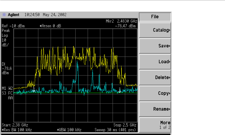
Step 5. Turn on the Max-hold feature and acquire the signal for two minutes. Save a screen
capture.
Step 6. Run Single Sweep two times, saving the screen captures for both sweeps. This gives a
reference for the worst case that is shown with the Max-hold in Step 5. Time can be
saved on this step if the Spectrum Analyzer is equipped with a dual trace option. Turn
Trace 2 on constant sweep and Trace 1 on Max-hold. After the Max-hold has
acquired a signal for two minutes, press the single sweep. Save the screen capture.
Refer to Figure E3, Max-hold Screen Capture.
Step 7. Repeat steps 5 and 6 with the following Start and Stop frequencies.
2.4GHz Band 2.6GHz Band
Start Stop Channel Start Stop
2.4GHz 2.45GHz E1 2.596GHz 2.602GHz
2.45GHz 2.5GHz F1 2.602GHz 2.608GHz
2.4GHz 2.41GHz E2 2.608GHz 2.614GHz
2.41GHz 2.42GHz F2 2.614GHz 2.62GHz
2.42GHz 2.43GHz E3 2.62GHz 2.626GHz
2.43GHz 2.44GHz F3 2.626GHz 2.632GHz
2.44GHz 2.45GHz E4 2.632GHz 2.638GHz
2.45GHz 2.46GHz F4 2.638GHz 2.644GHz
2.46GHz 2.47GHz
2.47GHz 2.48GHz
2.48GHz 2.49GHz
Figure E3: Max-hold Screen Capture
Navini Networks, Inc. Ripwave Base Station I&C Guide
Part #40-00047-00 Rev F v1.0 (TTA) 139
October 23, 2003
Time Domain
The Time Domain portion of the procedure is for unlicensed systems only.
Step 1. Set the Center Frequency to 2.4025GHz. Set the Resolution Bandwidth to 5 MHz.
Step 2. Set the Video Bandwidth to 1MHz.
Step 3. Set the Sweep Time to 40 ms.
Step 4. Set the Span to 0 Hz.
Step 5. Replace the antenna with a terminator to get a noise floor level. Save a screen capture.
Step 6. Set the display line to the noise floor level. The display line needs to stay on for all of
the following sweeps. This display line is used for a reference point and should be set
with the LNA powered on.
Step 7. Run the Single Sweep approximately 50 times and determine how often the
interference occurs. Save a screen capture of one worst case and one typical. See
Figure E4, Time Domain Screen Capture.
Step 8. Set the Sweep Time to 400 ms, and repeat Step 7.
Step 9. Repeat Steps 7 and 8 for an offset of 5MHz up to 24875MHz for 2.4 systems.

Ripwave Base Station I&C Guide Navini Networks, Inc.
140 Part #40-00047-00 Rev F v1.0 (TTA)
October 23, 2003
2.4GHz Band
Center Frequency
2.4075GHz
2.4125GHz
2.4175GHz
2.4225GHz
2.4275GHz
2.4325GHz
Up to 2.4875GHz
Step 10. If a directional antenna is used, repeat the Max-hold and Time Domain steps for each
direction.
Figure E4: Time Domain Screen Capture
Navini Networks, Inc. Ripwave Base Station I&C Guide
Part #40-00047-00 Rev F v1.0 (TTA) 141
October 23, 2003
Appendix F: Interference Sweep Tool
Overview
The Navini 2.4 GHz frequency Interference Sweep Test tool is used by an Installation &
Commissioning Technician or Field Engineer to sweep and collect data concerning RF conditions at
a specific site. The location is typically a site that has been identified as a potentially good candidate
for a Base Station installation.
The test tool manages the RF sweep and interference level conditions, with post-analysis performed
by RF Engineering personnel using simulation models. The results of the analysis are not a
guarantee of optimal operating conditions for the Ripwave system. The objective is to identify and
eliminate sites that might pose high potential problems in order to prioritize a given list of sites for
Base Station deployment.
Installation
Equipment
1. Navini Survey Test Box
2. 12 pin Control Cable
3. Laptop Computer
4. Power Box With Attached Ethernet Cable
5. Power Cable for the Power Box
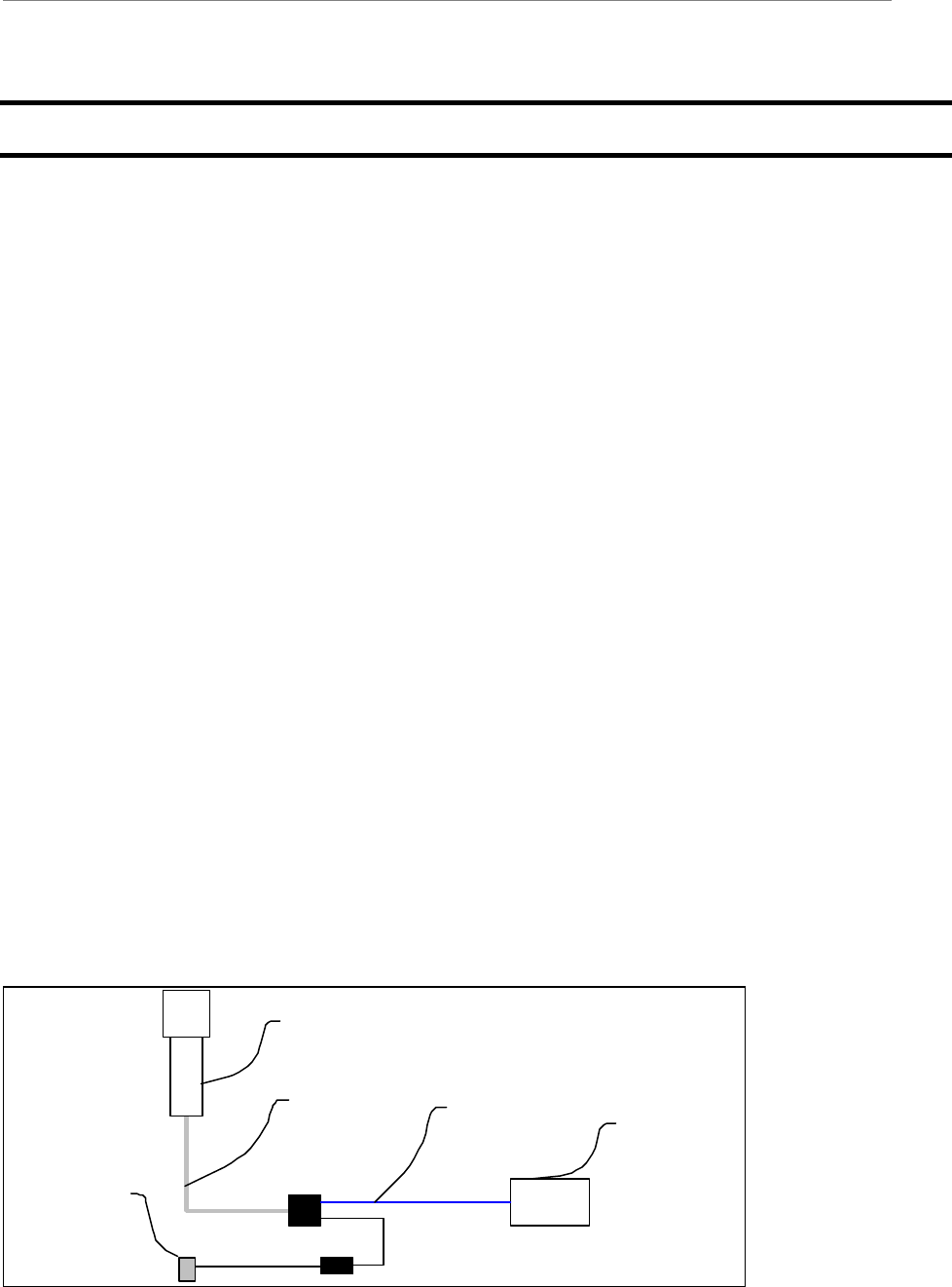
Figure F1 is a block diagram showing the requirements to install the equipment. Figure F2 provides
an example of the laptop and cable configuration.
Figure F1: Block Diagram
Navini Test Box
Laptop Computer
AC outlet
Control Cable Ethernet Cable
Ripwave Base Station I&C Guide Navini Networks, Inc.
142 Part #40-00047-00 Rev F v1.0 (TTA)
October 23, 2003
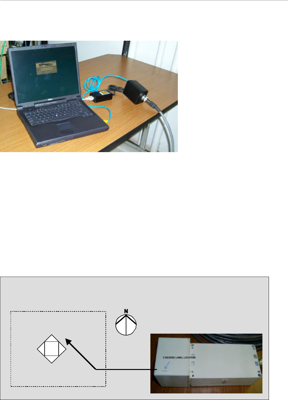
Figure F2: Laptop & Cable Configuration
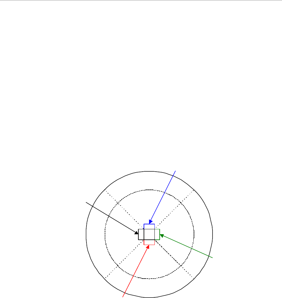
Mounting
The Navini Test Box should be installed in the location where the RFS will be installed, or as close
as possible. This will give the most accurate representation of the interference at the site. On the
upper portion of the test box there are three labels indicating 0, 120, and 240 degrees (Figure F3).
These are the antennas that are inside the test box. The label indicating 0 degrees should be pointed
as close to north as possible. Connect the Control Cable from the Navini Test Box to the Control
Box. The Control Box has a power connector, a circular control cable connector, and a blue
Ethernet cable on it. The Ethernet cable will be connected to your laptop.
Figure F3: Test & Control Box Setup
0 degrees
120 degrees
240 degrees
Top down view of
Navini Test Box
Control Box
0 degrees
120 degrees
240 degrees
Top down view of
Navini Test Box
Control Box
Navini Networks, Inc. Ripwave Base Station I&C Guide
Part #40-00047-00 Rev F v1.0 (TTA) 143
October 23, 2003
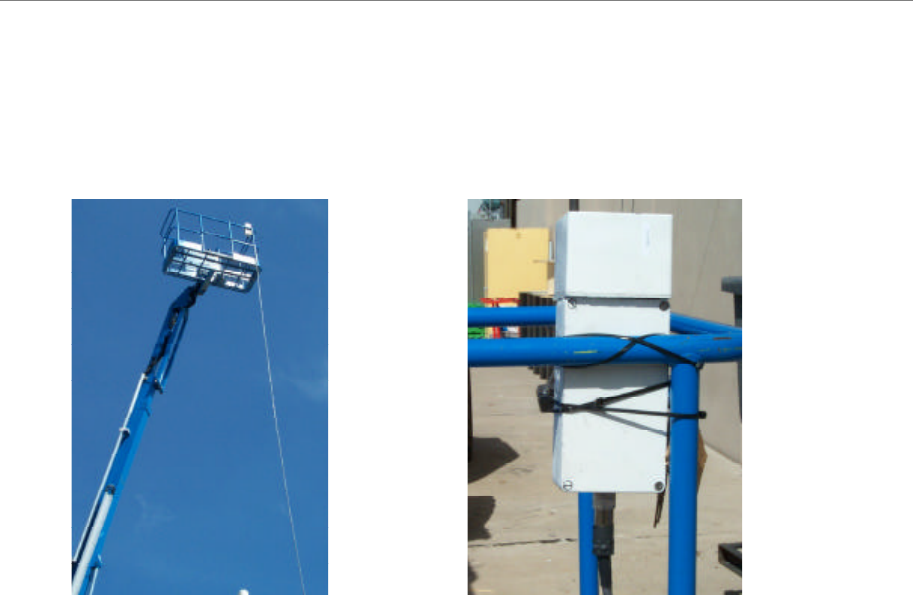
Figure F4 shows a sample of the mounting requirements for the installation.
Figure F4: Mounting Requirements
Using the Site Survey Tool
Recommended Settings
1. Interval Setting
Provided by Navini Networks RF planning group
2. Frequency Selection
2.400 to 2.476 GHz approved ISM operating frequency
3. Number of Frames for Gain Adjustment
Provided by Navini Networks RF planning group; site specific
4. Number of Stored Frames
Provided by Navini Networks RF planning group; site specific
Ripwave Base Station I&C Guide Navini Networks, Inc.
144 Part #40-00047-00 Rev F v1.0 (TTA)
October 23, 2003
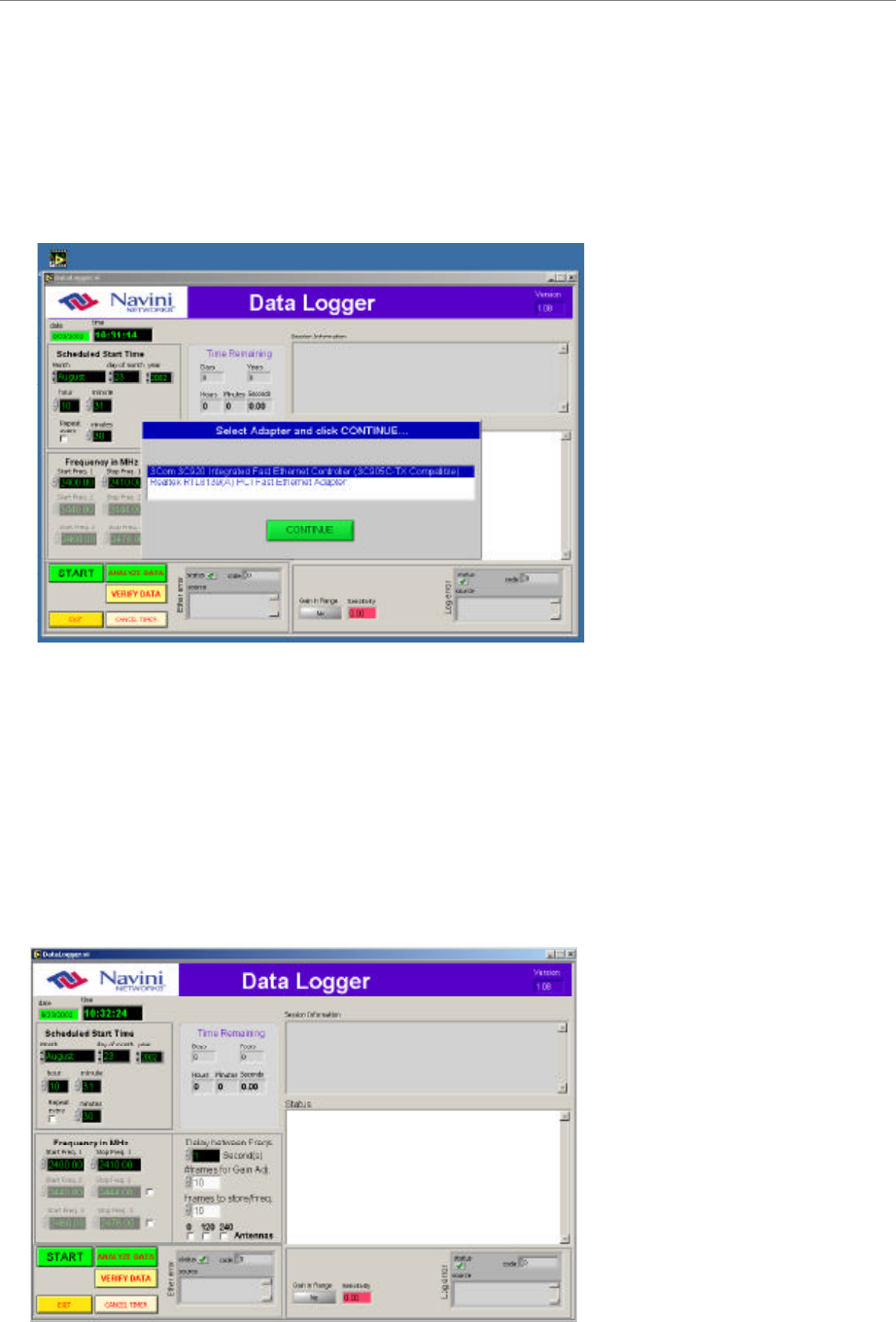
Procedure
Step 1. Open the application by selecting the Data Logger icon. Figure F5 shows the icon in the
background.
Figure F5: Data Logger
Step 2. Select the desired Ethernet adapter in the pop-up window.
Step 3. Starting in the upper left corner of the program screen, set the date and time for the
application to start its measurement interval. If the date and time set are earlier than the
current time, logging will begin immediately.
Step 4. If the measurement needs to be repetitive, determine the interval between measurements
by selecting the repeat box and entering the time interval (Figure F6).
Figure F6: Measurement Interval

Navini Networks, Inc. Ripwave Base Station I&C Guide
Part #40-00047-00 Rev F v1.0 (TTA) 145
October 23, 2003
Step 5. Select the frequencies to be measured.
a. There are 3 frequency band selections. By default two are not available until selected
by clicking on the white checkboxes to the right of each.
b. If you select more than one band, it is best if you put in some delay between each
band’s measurements, as mentioned in Step 6 below.
Step 6. If more than one frequency band has been selected, choose the delay to be used between
each band’s measurements. You can use the scroll bar or just type in the interval.
Step 7. Select the number of frames for Gain Adjust. This allows the system to calculate the
Modem’s receiver sensitivity.
Step 8. Select the number of frames to be stored for analysis. The same number will be captured
for each frequency band if more than one is selected.
Step 9. Ensure antenna orientation is selected properly. It takes about 1 second to log one frame
of data. Therefore:
Elapsed time = #antSelected ? [(number_of_gain_adj Frames) ? n + (Freq_Range/2) ?
#of_framesToLog + (Freq_Range/2) ? delayBetweenFreqs]
Where n is the number of gain adjustment loops. Up to 10 are possible if the received
signal varies to a great extent in amplitude from frame to frame.
Step 10. Select the Start button.
Step 11. Enter in the desired Site Name in the pop-up window, and press Enter to start the
measurements.
Step 12. To stop the measurement, select the Abort button.
Step 13. PC and Test operation should be validated every 3-4 hours for working order.
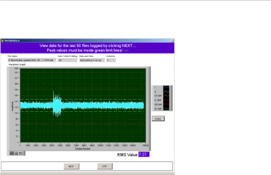
To Verify the Data
Step 1. Click the Verify Data button. The screen shown in Figure F7 appears. The last 50
data files logged can be viewed with this screen. Click on NEXT to view the next file.
Ripwave Base Station I&C Guide Navini Networks, Inc.
146 Part #40-00047-00 Rev F v1.0 (TTA)
October 23, 2003
Figure F7: Verify Data
Analysis of Data
Not available on this release.
FTP Instructions
Step 1. Launch FTP Pro.
Step 2. Select the file, “Rfsweep”.
Step 3. The FTP Password is provided by Navini in a separate document.
Step 4. To transfer the file, locate the Navinidatalog folder on the “C” drive of the laptop.
Step 5. Select all files in the data folder via FTP browser, then, send the files.
Step 6. Once the file transfer is complete, delete the data folder and rename the “gain.adj” file for
the next test sequence. Create a new “gain_adj” folder under the NaviniDataLog folder.
Navini Networks, Inc. Ripwave Base Station I&C Guide
Part #40-00047-00 Rev F v1.0 (TTA) 147
October 23, 2003
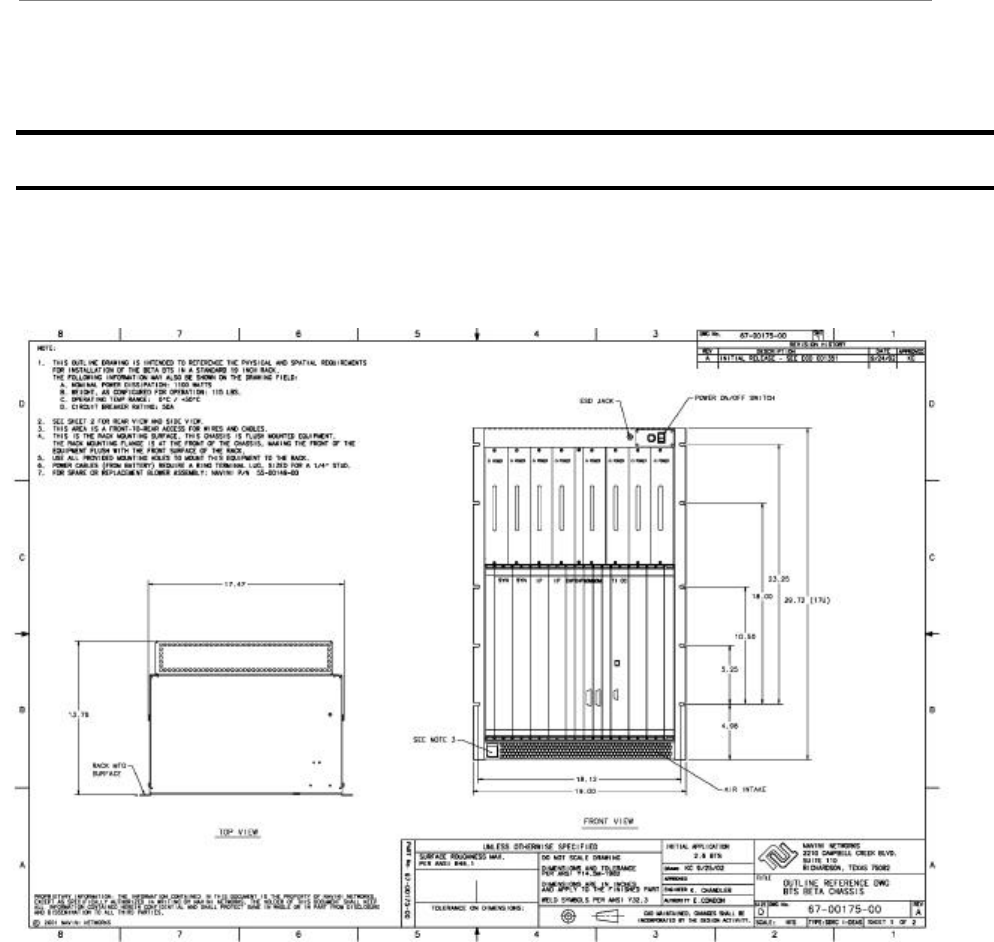
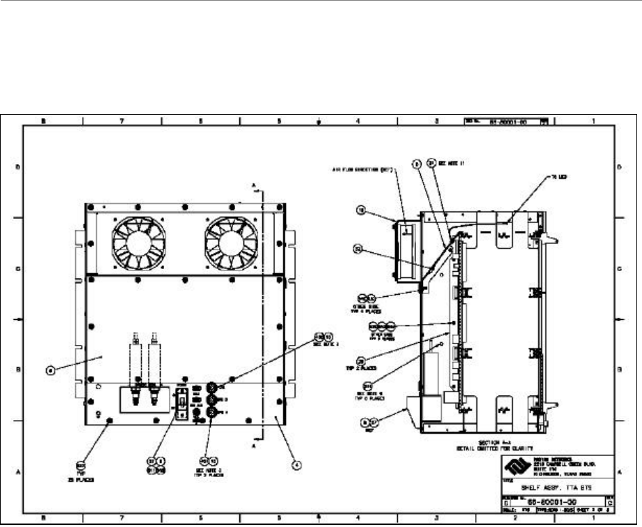
Appendix G: BTS Specifications
Figure G1: Combo Chassis (Front)
Ripwave Base Station I&C Guide Navini Networks, Inc.
148 Part #40-00047-00 Rev F v1.0 (TTA)
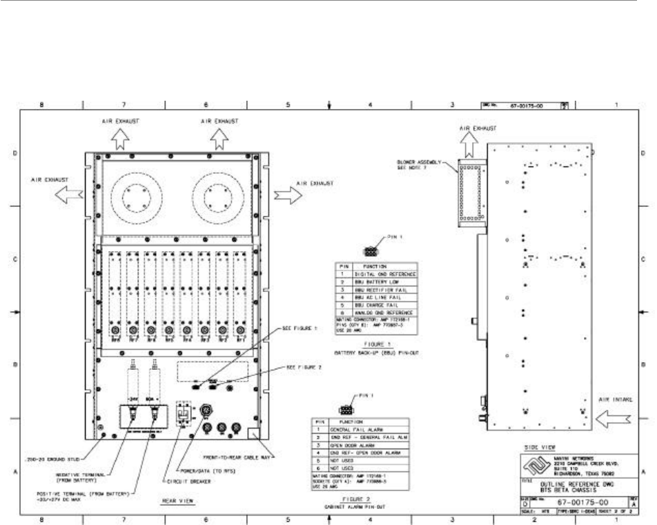
October 23, 2003
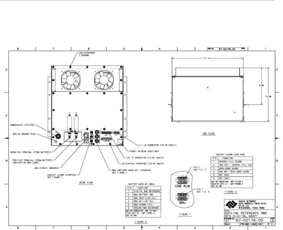
Figure G2: Combo Chassis (Back)
Navini Networks, Inc. Ripwave Base Station I&C Guide
Part #40-00047-00 Rev F v1.0 (TTA) 149
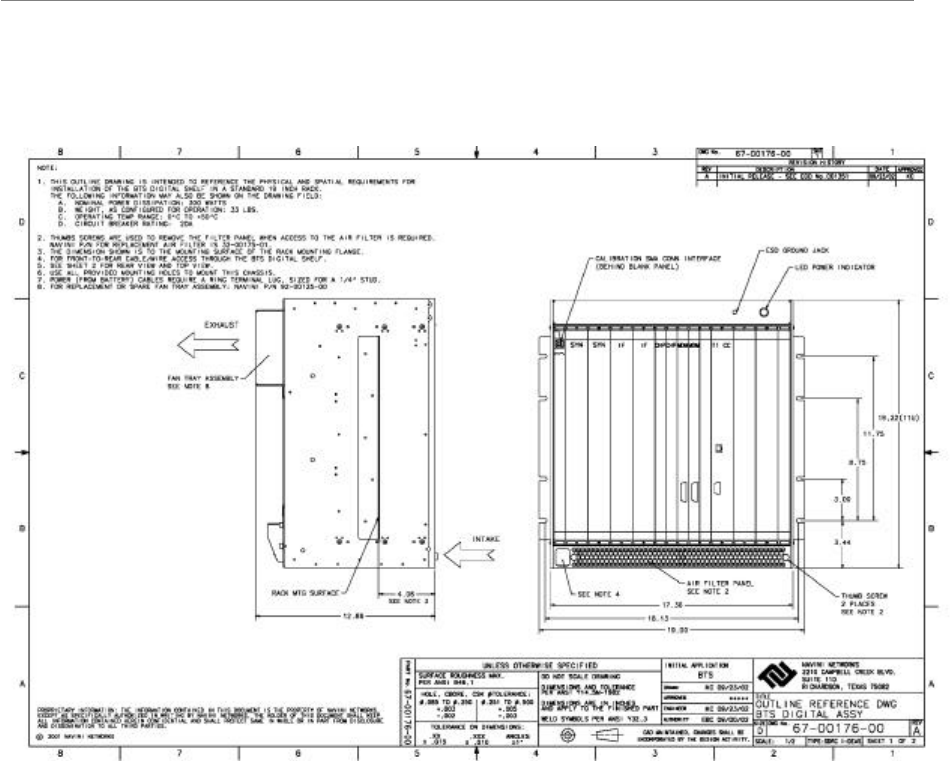
October 23, 2003
Figure G3: Split Digital Chassis (Front)
Ripwave Base Station I&C Guide Navini Networks, Inc.
150 Part #40-00047-00 Rev F v1.0 (TTA)
October 23, 2003
Figure G4: Split Digital Chassis (Back)
Navini Networks, Inc. Ripwave Base Station I&C Guide
Part #40-00047-00 Rev F v1.0 (TTA) 151
October 23, 2003
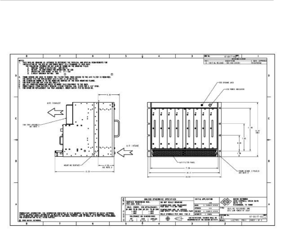
Figure G5: Split RF Chassis (Front)
Ripwave Base Station I&C Guide Navini Networks, Inc.
152 Part #40-00047-00 Rev F v1.0 (TTA)
October 23, 2003
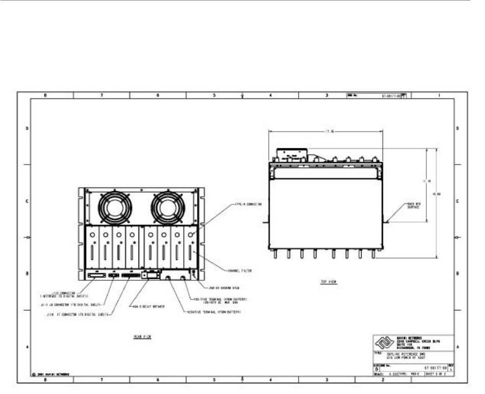
Figure G6: Split RF Chassis (Back)
Navini Networks, Inc. Ripwave Base Station I&C Guide
Part #40-00047-00 Rev F v1.0 (TTA) 153
October 23, 2003
Figure G7: TTA Digital Chassis (Front)
Ripwave Base Station I&C Guide Navini Networks, Inc.
154 Part #40-00047-00 Rev F v1.0 (TTA)
October 23, 2003
Figure G8: TTA Digital Chassis (Back)
Navini Networks, Inc. Ripwave Base Station I&C Guide
Part #40-00047-00 Rev F v1.0 (TTA) 155
October 23, 2003
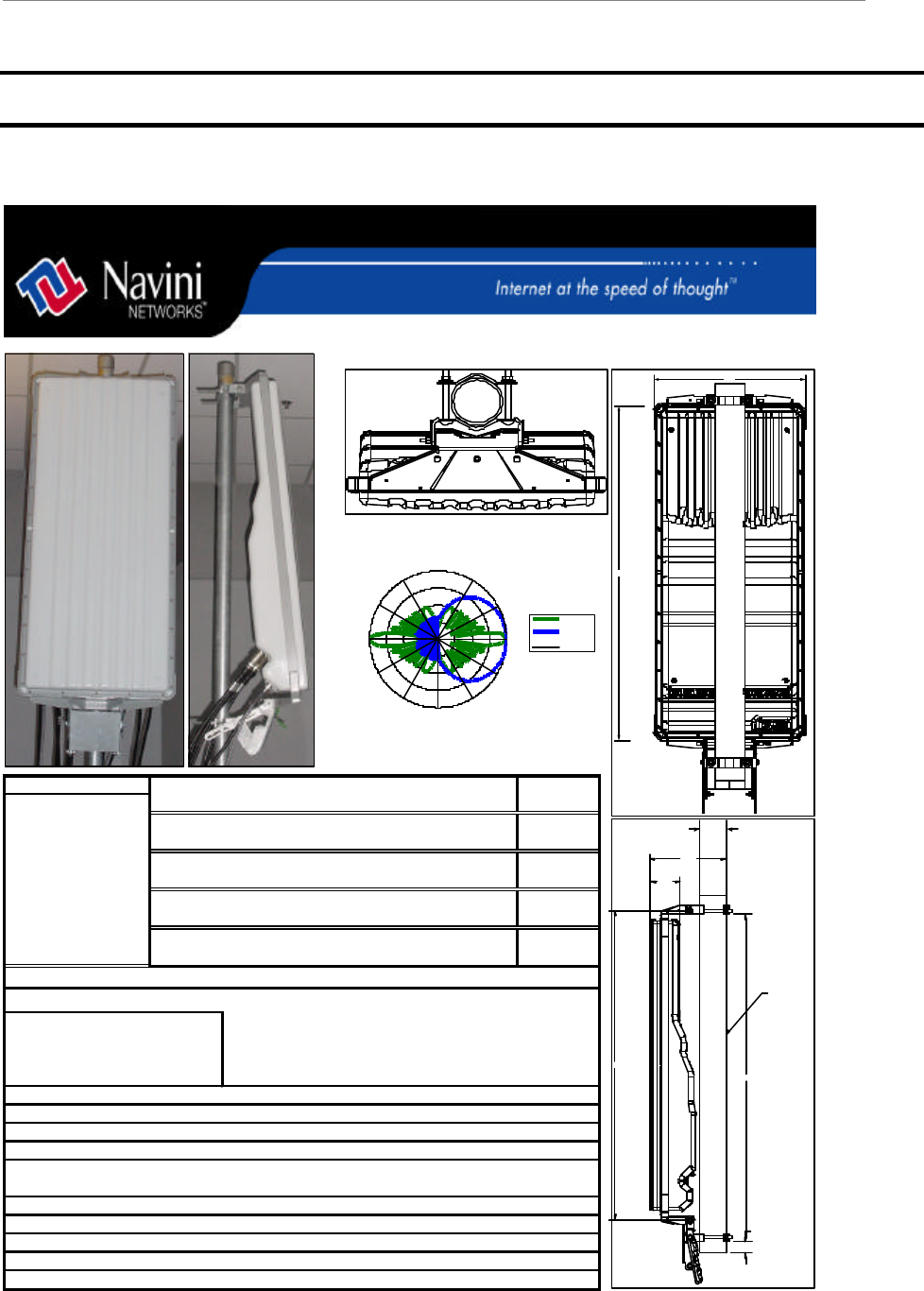
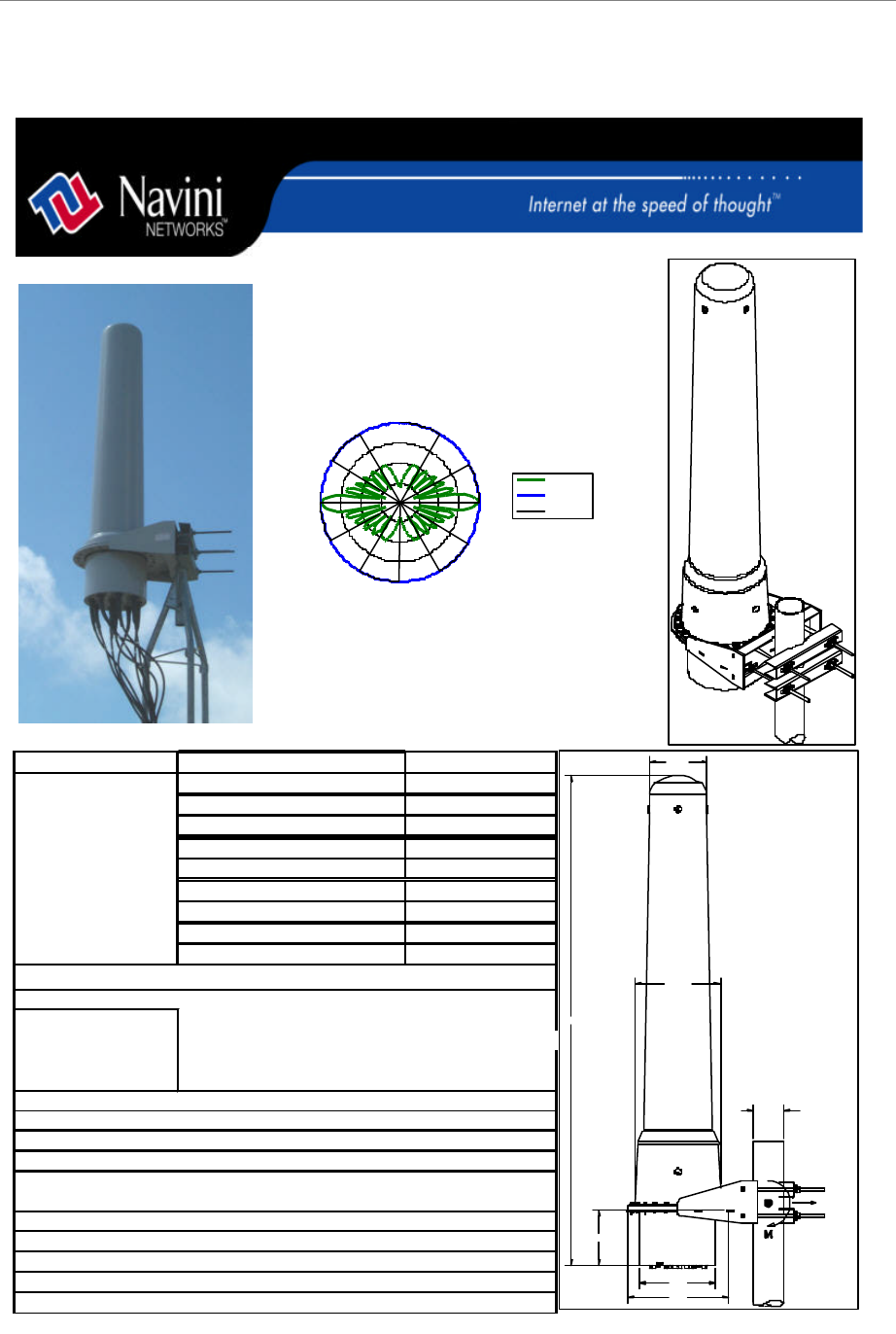
Appendix H: RFS Data Sheets
Figure H1: Panel
NAVINI PART NUMBER: 95-23000-00
95-23100-00
95-23000-05
95-23100-05
95-00043-05
95-10043-05
95-25000-00
95-25100-00
95-00005-05
95-10005-05
DESCRIPTION
Frequency Range
Polarization
Antenna Gain
Horizontal HPBW
Vertical HPBW
Connector Type's
Lateral Thrust at 100 MPH (161 KM/HR) w/o ice
Mounting Configurations
Electrical Downtilt
Mechanical Downtilt/Uptilt
Weight
2.4GHz w/o LNAs
2.5GHz ABCD with LNAs
2.5GHz ABCD w/o LNAs
220 LB. Lateral Load
To Pipe Mount - 2 3/4" TO 3" OD
2.4GHz range = 2.4GHz through 2.473GHz
2.5GHz range = 2.500GHz through 2.596GHz
2.6GHz EFGH range = 2.596GHz through 2.686GHz
9 Female "N" Type
17-17.5 dBi for 120 Degree Sectored
6 Degrees
2.3GHz Low Band
Vertical
2.6GHz EFGH with LNAs
2.6GHz EFGH w/o LNAs
2.3GHz High Band
2.3GHz Low Band w/o LNAs
2.3GHz High Band w/o LNAs
2.3GHz low band range = 2.305GHz Through 2.320GHz
2.3GHz high band = 2.345GHz through 2.360GHz
2.4GHz with LNAs
81 LB. Including Bracket Mount no pipe
Broadband Sectored Panel Antenna
Navini RFS
6 Degrees
0 - 10 Degrees Mechanical
1 - 12 Pin Female Circular
130 Degrees
Panel RFS Antenna Pattern
-20.00
-15.00
-10.00
-5.00
0.00
Vertical
Horizontal
Scale
57.5"
2"
12.6"
54.5"
5"
GALVANIZED
ANTENNA
MOUNTING
PIPE
4.5 OD pipe
sch 40 pipe
53.4"
22.9"
Ripwave Base Station I&C Guide Navini Networks, Inc.
156 Part #40-00047-00 Rev F v1.0 (TTA)
October 23, 2003
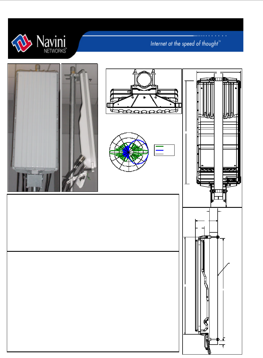
Figure H2: Panel TTA
NAVINI PART NUMBER: 95-00043-10
DESCRIPTION
Frequency Range
Polarization
Antenna Gain
Horizontal HPBW
Vertical HPBW
Connector Type's
DC Power Dissipation
Lateral Thrust at 100 MPH (161 KM/HR) w/o ice
Mounting Configurations
Electrical Downtilt
Mechanical Downtilt/Uptilt
Weight
2.4GHz TTA RFS
220 LB. Lateral Load
To Pipe Mount - 2 3/4" TO 3" OD
2.4GHz range = 2.4GHz through 2.483GHz
9 Female "N" Type
17-17.5 dBi for 120 Degree Sectored
6 Degrees
Vertical
81 LB. Including Bracket Mount no pipe
Broadband Sectored Panel Antenna
Navini RFS
6 Degrees
0 - 10 Degrees Mechanical
80 Watts
130 Degrees
Panel RFS Antenna Pattern
-20.00
-15.00
-10.00
-5.00
0.00
Vertical
Horizontal
Scale
57.5"
2"
12.6"
54.5"
5"
GALVANIZED
ANTENNA
MOUNTING
PIPE
4.5 OD pipe
sch 40 pipe
53.4"
22.9"
Navini Networks, Inc. Ripwave Base Station I&C Guide
Part #40-00047-00 Rev F v1.0 (TTA) 157
October 23, 2003
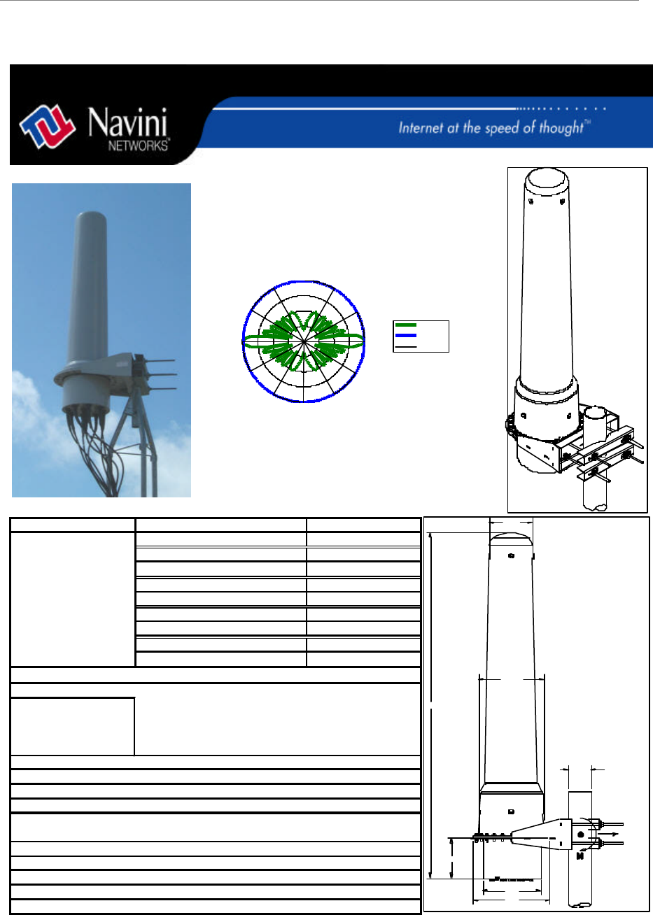
Figure H3: Omni
P/N 44-00038-01 Rev A v1.0 Feb.14, 2003
NAVINI PART NUMBERS:
note: * 02 or 12 are for degree of
downtilt also available are 04 and
14
** xx is the degree of downtilt
02 or 04.
Frequency Range
Polarization
Antenna Gain
Horizontal HPBW
Vertical HPBW
Connector Type's
Lateral Thrust at 100 MPH (161 KM/HR) w/o ice
Mounting Configurations To Pipe Mount
Electrical Downtilt
Mechanical Downtilt
Weight
2.3GHz- high band without LNAs
95-23008-12*
95-23108-02*
95-23108-12*
95-23008-02*
2.3GHz- low band with LNAs
2.3GHz- high band with LNAs
2.3GHz- low band without LNAs
95-24008-xx**
2.4GHz- with LNAs
2.4GHz- without LNAs
2.5GHz- with LNAs
95-24108-xx**
N/A
73 lbs. Including mount
2 and 4 Degree
11.5dBi
Omni
132 LB. Lateral Load
6 Degrees
9 Female "N" Type
1 - 12 Pin Female Circular
DESCRIPTION
Broadband Omnidirectional Antenna
Navini RFS
95-25008-xx**
95-25108-xx**
95-26008-xx**
95-26108-xx**
2.5GHz- without LNAs
2.6GHz- EFGH with LNAs
2.6GHz- EFGH without LNAs
2.6GHz EFGH range = 2.596GHz through 2.686GHz
Vertical
2.3GHz low band range = 2.305GHz Through 2.320GHz
2.3GHz high band = 2.345GHz through 2.360GHz
2.4GHz range = 2.4GHz through 2.473GHz
2.5GHz range = 2.500GHz through 2.596GHz
Omni RFS Antenna Pattern
-20.00
-15.00
-10.00
-5.00
0.00
Vertical
Horizontal
Scale
13.057"
73.5"
11.7"
15.5"
8.5"
8.9"
R
Ø3.0-Ø4.5 OD PIPE
FR
Ripwave Base Station I&C Guide Navini Networks, Inc.
158 Part #40-00047-00 Rev F v1.0 (TTA)
October 23, 2003
Figure H4: Omni TTA
NAVINI PART NUMBERS:
Frequency Range
Polarization
Antenna Gain
Horizontal HPBW
Vertical HPBW
Connector Type's
DC Power Dissipation
Lateral Thrust at 100 MPH (161 KM/HR) w/o ice
Mounting Configurations To Pipe Mount
Electrical Downtilt
Mechanical Downtilt
Weight
Vertical
2.4GHz range = 2.4GHz through 2.483GHz
DESCRIPTION
Broadband Omnidirectional Antenna
Navini RFS
N/A
73 lbs. Including mount
2 and 4 Degree
11.5dBi
Omni
132 LB. Lateral Load
6 Degrees
9 Female "N" Type
80 Watts
95-24018-02
2.4GHz TTA RFS, 2 degree downtilt
Omni RFS Antenna Pattern
-20.00
-15.00
-10.00
-5.00
0.00
Vertical
Horizontal
Scale
13.057"
73.5"
11.7"
15.5"
8.5"
8.9"
R
Ø3.0-Ø4.5 OD PIPE
FR

Navini Networks, Inc. Ripwave Base Station I&C Guide
Part #40-00047-00 Rev F v1.0 (TTA) 159
October 23, 2003
Appendix I: BTS Outdoor Enclosure Manufacturers
General
Navini Networks does not manufacture external cabinets for the Ripwave BTS. The following lists
two manufacturers who are positioned to provide external cabinets for the Navini system. Inclusion
of the manufacturers on this list does not represent an endorsement of the manufacturer or its
products by Navini Networks.
Manufacturers List
Purcell Systems
22924 E. Appleway Avenue
Liberty Lake, WA 99019
509 755-0341
Steve Busby
Http://www.purcellsystems.com/
Hendry Telephone Products
55 Castillan Drive
Santa Barbara, CA 93117
805 571-8287
Phil Skeen

Ripwave Base Station I&C Guide Navini Networks, Inc.
160 Part #40-00047-00 Rev F v1.0 (TTA)
October 23, 2003

Navini Networks, Inc. Ripwave Base Station I&C Guide
Part #40-00047-00 Rev F v1.0 (TTA) 161
October 23, 2003
Appendix J: Rectifier/BBU Suppliers
General
This section includes contact information for two rectifier/BBU suppliers. Inclusion of a supplier on
this list does not represent an endorsement of the supplier or its products.
Suppliers List
Valere Power Systems
651 N. Plano Road, Suite 421
Richardson, TX 75081
469 330-9100
Matt McManus
Argus DC Power
Argus Regional Sales Manager
Addison, IL
630 530-5006
Richard Meyer
http://www.argusdcpower.com/
Regulatory
Reference Chapter 1, Page 8 “Regulatory Information” requirements.

Ripwave Base Station I&C Guide Navini Networks, Inc.
162 Part #40-00047-00 Rev F v1.0 (TTA)
October 23, 2003
Navini Networks, Inc. Ripwave Base Station I&C Guide
Part #40-00047-00 Rev F v1.0 (TTA) 163
October 23, 2003
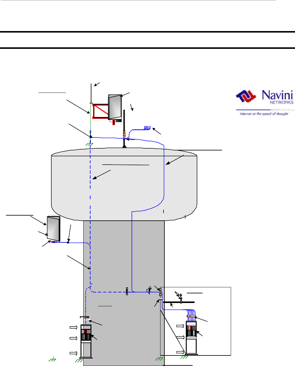
Appendix K: Sample Base Station Drawing
Figure K1: Sample Base Station Drawing
NAVINI NETWORKS
BASE STATION LAYOUT
WATER TOWER OPTION
PANEL ANTENNA
PSX-ME
SURGE
PROTECTOR
GROUND
BAR
RF CABLES
ANTENNA
BRACKET
GPS
CABLE
LADDER
CABLE
ENTRY
GROUND
BAR
ETHERNET
/ TELCO
SHELTER / HUT
OPTION 1
INDOOR BTS
OVERHEAD CABLE LADDER
24VDC
@ 60A
CABINET
GND
PSX
GROUND BAR
NAVINI
BTS
24VDC
@ 60A
CABINET
GND
PSX
GROUND BAR
NAVINI
BTS
ETHERNET
/ TELCO
OPTION
2
INDOOR BTS
CABLE RUN / CABLE LADDER
OPTION 3
CABLE RUN / INTERNAL RUN
OPTION 4
LIGHTNING
ROD
RF CABLES
CORE TO INSIDE
OF TOWER
PANEL
ANTENNA
BTS Opt 1
Indoor
PANEL
ANTENNA
BTS Opt 2
Indoor
PSX-ME
SURGE
PROTECTOR
PANEL LOCATION
OPTION 5
PANEL LOCATION
OPTION 6

Ripwave Base Station I&C Guide Navini Networks, Inc.
164 Part #40-00047-00 Rev F v1.0 (TTA)
October 23, 2003
NOTE
1.CABLE BUNDLE CONSIST OF 9 RF CABLES AND 1 POWER/DATA CABLE
2.RF CABLE TYPE TO BE DETERMINED BASED ON RUN LENGTH AND DB
LOSS/FT
3.CABLE HANGERS TO BE SPECIFIED/RECOMMENDED BY TOWER CREW
4.ANTENNA BRACKET TO BE SUPPLIED BY CUSTOMER AS RECOMMENDED BY
TOWER CREW
5.BTS REQUIRES 24VDC @ 60A.
6.PSX-ME SURGE PROTECTORS TO BE INSTALLED IN-LINE BETWEEN RF
CABLE AND ANTENNA
7.PSX SURGE PROTECTOR TO BE MOUNTED ON GROUND BAR CLOSE TO BTS
CABINET/CHASSIS
8.ETHERNET/TELCO BACKHAUL TO BE PROVIDED BY CUSTOMER
9.ALL INSTALLED EQUIPMENT/MATERIALS MUST BE PROPERLY GROUNDED
10.OPTION 1 IS FOR AN INDOOR BTS INSTALL, OPTION 2 IS FOR
OUTDOOR BTS
CUSTOMER
SITE NAME
LOCATION
1PANEL LOCATION OPTION 5=DOME TOP 6=SIDE
2ANTENNA BRACKET TYPE
3PSX-ME SURGE PROTECTOR PCS
4ANTENNA AZIMUTH
5
6DEGREES
7FEET
8
ANTENNA HEIGHT
ANTENNA DOWNTILT
TOWER JUMPER LENGTH
TOWER JUMPER CABLE TYPE
9
10 FEET
11 PCS
12
13 PCS
14 GROUNDING CABLE LENGTH FEET
15 PCS
16 PCS
WEATHERPROOFING KIT
GROUNDING KIT
HOISTING GRIP
MAIN FEEDER TYPE
MAIN FEEDER LENGTH
GROUND BUSS BAR
CABLE HANGER TYPE
17
18 GPS CABLE LENGTH FEET
19 GPS CABLE TYPE
GPS MOUNT
20 LOCATION OPTION 1=SHELTER 2=INSIDE TOWER
21 CABLE RUN OPTION 3=EXTERNAL 4=INTERNAL
22 JUMPER CABLE LENGTH FEET
23 JUMPER CABLE TYPE
24 PSX SURGE PROTECTOR PCS
25 GPS SURGE PROTECTOR PCS
26 ALT GROUND BUSS BAR PCS
27 24VDC/60A POWER SUPPLY
28 INDOOR RACK/CABINET

Navini Networks, Inc. Ripwave Base Station I&C Guide
Part #40-00047-00 Rev F v1.0 (TTA) 165
October 23, 2003
Appendix L: Antenna Power & Cable Selection
Overview
This section provides formulas and data that are necessary inputs for determining the right cable to be
measured, cut, and installed. There are 3 types of cables that are part of the Base Station installation: antenna
cables, calibration (cal) cable, and data/power cable.
The antenna cables are the eight cables that carry amplified RF signals. They run between the RF/PA cards
and the 8 antenna elements. The calibration (cal) cable is a single RF coaxial cable that provides an RF
feedback path for calibrating the system. It runs between the backplane of the digital shelf and the RFS. The
data/power cable may or may not be a separate cable from the cal cable. It is possible to use different types of
cable with different loss factors for the antenna cables and cal cable. The formulas presented in this section
call for either an antenna cable loss or a cal cable loss. Most applications deploy the same cable type for both
the antenna and cal cables.
To determine the type of cable and acceptable loss of that cable for a site, the operating transmit and receive
range must be known. This is commonly referred to as the maximum transmit output power and the receiver
sensitivity range. The operating transmit power and receive range should have been identified during the site
survey, or they may be based on regulatory compliance.
Determining the cable type and acceptable loss for a site are typically driven by two goals: (1) Which is the
least expensive cable; and (2) Which has the higher (normally) loss. Whether or not the goals are achieved is
determined by the output power. For example, the maximum transmit output power for a 2.6 Base Station
might be given as +30dBm, or 1 Watt, to the antenna. An example of receiver sensitivity for a 2.6 system
would be given as – 80 to –90 dBm.
In addition to cable power loss, other types of loss have to be factored - for example, the calibration board.
The calibration board is part of the RFS that samples the energy being transmitted from or received by the 8
antenna elements and combines that energy which is used when performing a calibration on the Base Station.
This loss, plus cable loss and other types of loss in the equipment are called out in the following procedure.
Procedure
Read and follow the 7 steps/formulas below, in the order shown, to determine the resulting PA/RFS output
power and desired transmit and receive calibration range for the type of Base Station you will be installing.
Refer to Tables L1 and L2 to complete the steps. Table L1 provides Base Station operating parameters based
on system type (2.3, 2.4, etc.), as well as other variables. Table L2 provides cable attenuation data. Before you
begin, read through the steps/formulas, notes, and Table L1 in detail. Refer to the column letters at the top of
Table L1 to locate the appropriate values requested in some of the formulas. Note that step/formula 1 contains
a sub-procedure for determining antenna cable loss using Table L2.
Ripwave Base Station I&C Guide Navini Networks, Inc.
166 Part #40-00047-00 Rev F v1.0 (TTA)
October 23, 2003
Determine the maximum capable BTS output power to the antenna.
= [(PA Output to Meet FCC) or (to Meet SNR)] – BTS Loss – RFS Loss – BTS Antenna Cable Loss*
[Column A or B]1 – [Column E]2 – [Column F or G] – [Calculated* or Measured]
?? BTS Antenna Cable loss < 18 dB for ACTIVE RFS configurations
?? BTS Antenna Cable loss < 8 dB for PASSIVE RFS configurations
Change the EMS settings accordingly.
*Sub-procedure: Calculate BTS antenna cable loss, referring to Table 8.
= [[Distance (length in ft) 100 ft] x Attenuation value/cable type] + 0.6 for 6 connectors/3 cables
Determine the maximum BTS output power that can be calibrated.
= Max Synth Input + Cal Cable Loss + Min Cal Board Loss3 + Backplane Loss4
[Column K] + [Calculated or Measured] + [Note 3] + [Default of 5.0 in EMS or Measured]
Determine the actual** max BTS output power available to the antenna.
= The lesser of the two values of Step/Formula 1 and Step/Formula 2 (aka, the “floor”)
** Actual is what you can calibrate the BTS at.
Determine the minimum BTS output power that can be calibrated .
= Min Synth Input + Cal Cable Loss + Max Cal Board Loss3 + Backplane Loss4
[Column J] + [Calculated or Measured] + [Note 3] + [Default of 5.0 in EMS or Measured]
Determine the actual** maximum EIRP.
= Step/Formula 3 + Antenna Gain. The antenna gain is affected by the type of antenna (omni, panel, 2.3,
2.4, etc.) and refers to the values in the RFS Configuration Script that accompanied the antenna from
Manufacturing.
**Actual is what you can calibrate the BTS at.
Determine the minimum BTS RX input power that can be calibrated.
= Min Synth Output - Cal Cable Loss - Min Cal Board Loss3 - Backplane Loss4
[Column H] - [Calculated or Measured] - [Note 3] - [Default of 5.0 in EMS or Measured]
Determine the maximum BTS RX input power that can be calibrated.
= Max Synth Output - Cal Cable Loss -Max Cal Board Loss3 - Backplane Loss4
[Column I] - [Calculated or Measured] - [Note 3] - [Default of 5.0 in EMS or Measured]
Step/Formula
1
Step/Formula
2
Step/Formula
4
Step/Formul
a
3
Step/Formula
5
.
.
.
.
Step/Formula
6
Step/Formula
7
Antenna
Cable
Selection
Cal
Cable
Selection

Navini Networks, Inc. Ripwave Base Station I&C Guide
Part #40-00047-00 Rev F v1.0 (TTA) 167
October 23, 2003
NOTES
1This note pertains to Step/Formula 1: For PA_Output_Power, if in the U.S. use Column A. If outside the U.S., as a
precaution contact Navini Technical Support (Engineering) for sign-off. The value input cannot be more than the
value shown in Column B.
2This note pertains to Step/Formula 1: BTS_Loss is either (a) loss with a filter - i.e., if operating in the U.S. or other
market that requires a filter, or (b) loss with a bypass cable. The first number (+1) is the correct value if a standard
filter is used. The second number (0.4) is the correct value if a bypass cable is used. In Column D, for a 2.3 GHz
system the values are the same for both the 8-carrier and the 10-carrier systems.
3Min loss in Cal Board is 27 dB. Max loss in Cal Board is 31 dB.
4In the EMS the backplane loss will show 5.0 as default. Actual measured loss will be indicated on the back of the
chassis.
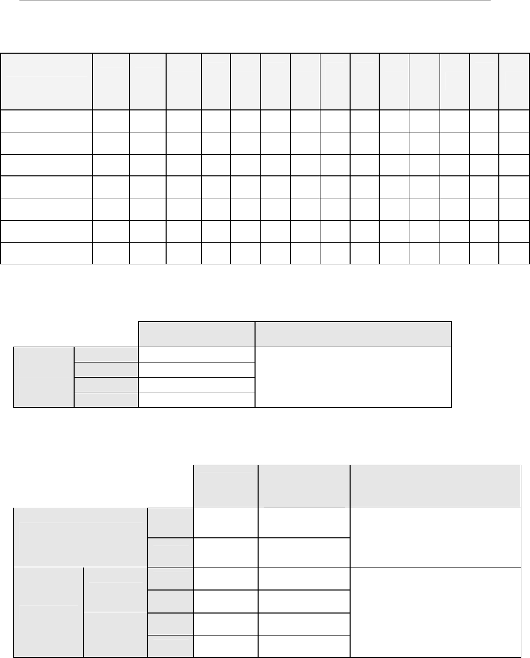
Table 7: Transmitter Operating Parameters
A B C D E F G H I J K
PA Max
Output
Power to
Meet
FCC
Limits
(dBm)
PA Max
Output
Power
(dBm)
PA Min
Output Power
Before
Damage
Level or Auto
Shutdown*
(dBm)
Max
Antenna
Terminal
Power to
Meet FCC
Limits
(dBm)
BTS Loss
With
Standard
Filter /
Bypass
Cable**
(dB)
Active
RFS
Loss
Type
(dB)
Passive
RFS
Loss
Type**
* (dB)
Synth
Min
Outpu
t
(dBm)
Synth
Max
Output
(dBm)
Synth
Min
Input
(dBm)
Synth
Max
Input
(dBm)
2.3
(6 carrier) +38 +40 +42 +30
1 / 0.4
Block Filter
has 1.0 dB
max insertion
loss
3.2 1.7 -60 -32 -23 +0
2.3
(8 carrier) +38 +40 +42 +30
1 / 0.4
Block Filter
has 1.0 dB
max insertion
loss
3.2 1.7 -60 -32 -23 +0
2.3
(10 carrier) +37 +40 +42 +30
1 / 0.4
Block Filter
has 1.0 dB
max insertion
loss
3.2 1.7 -60 -32 -23 +0
2.4 (combo) +37 +37 +42 +17.5 0.4 Bypass 3.2 1.7 -50 -20 -35 -10
2.5 +39 +41 +42 Limited by
Cable Loss
1.0 / 0.4
Channel Filter
has 1.0 +/- 0.2
dB insertion
loss
3.2 1.7 -60 -32 -23 +0
2.6
(EFGH
Split) +39 +41 +42 Limited by
Cable Loss
1.0 / 0.4
Channel Filter
has 1.0 +/- 0.2
dB insertion
loss
3.2 1.7 -60 -32 -23 +0
2.6
(EF Combo) +37 +41 +42 Limited by
Cable Loss
1.8 / 0.4
Channel Filter
has 1.8 +/- 0.2
dB including
cable to
backplane
3.2 1.7 -60 -30 -20 +0
* The lowest value at which 2.3, 2.5, and 2.6 EFGH PAs will shut down automatically. There is no auto shutdown for 2.4 and 2.6 EF combo systems.
** The value at which the bypass does not meet FCC limits.
***Passive configurations of BTS affect system Noise figure. For passive systems other than 2.4, consult SYSTEMS ENGINEERING.
Ripwave Base Station I&C Guide Navini Networks, Inc.
168 Part #40-00047-00 Rev F v1.0 (TTA)
October 23, 2003
Table L2: Cable Attenuation in dB per 100 Feet
Cable Type 2 ¼?
LDF
12-50
1 5/8?
LDF 7-
50A
LMR
1700
1 ¼?
LDF
6-
50A
LMR
1200
7/8?
LDF
5-
50A
LMR
900
5/8?
LDF
4.5-
50A
½ ?
LDF
4-
50A
LMR
600
½ ?
Super
flex
FSJ
4-
50B
LMR
500
3/8?
LDF
2-
50A
LMR
400
Frequency/Size 2.350 1.980 1.670 1.550 1.200 1.090 0.870 0.865 0.630 0.590 0.520 0.500 0.440 0.405
2000 MHz 0.994 1.11 1.5 1.42 1.99 1.82 2.64 2.27 3.25 3.9 5.09 4.84 5.17 6
2400 MHz N/A 1.24 1.7 1.5 2.2 2.02 2.9 2.52 3.63 4.3 5.67 5.4 5.67 6.6
2500 MHz N/A 1.27 1.71 1.53 2.26 2.07 3 2.58 3.70 4.42 5.8 5.48 5.79 6.8
2600 MHz N/A 1.3 1.8 1.57 2.3 2.12 3.1 2.64 3.78 4.5 5.94 5.6 5.91 6.9
Weight lbs/ft 1.22 0.82 0.74 0.63 0.45 0.33 0.27 0.15 0.15 0.13 0.14 0.1 0.08 0.07
Bend Radius (inches) 24 20 13.5 15 6.5 10 3 8 5 1.5 3 1.25 3.75 1
Table L3: 2.4 GHz TTA BTA Max Power and Frequency Range Supported
Max Power Frequency Range Supported
Omni 17.5 dBm
US Sector 16 dBm
Omni 24 dBm
ETSI Sector 18 dBm
2.400 to 2.483 GHz
Table L4: 2.4 GHz TTA BTA Cable Loss and Corresponding Cable Length
Cable
Loss
Calculated
Length of RG6
Bundled Cable Engineering Notes
Min 5 dB 40 ft (12 m)
US
(Omni & Sector) Max(1)
20 dB 180 ft (55 m)
For a cable loss of more than 15 dB,
Adjacent Channel Power degradation
will occur.
At 20 dB of cable loss a minimum
ACP degradation of 3dB will occur
Min 5 dB 40 ft (12 m)
Omni Max(2)
20 dB 180 ft (55 m)
Min 5 dB 40 ft (12 m)
ETSI
Sector Max(1)
20 dB 180 ft (55 m)
For a cable loss of more than 15 dB,
Adjacent Channel Power degradation
will be dominated by RFC.
At 20 dB of cable loss RFC SNR will
be approaching 30 dB

Navini Networks, Inc. Ripwave Base Station I&C Guide
Part #40-00047-00 Rev F v1.0 (TTA) 169
October 23, 2003
Table L5: 3.5 GHz TTA BTA Max Power and Frequency Range Supported
Max Power Frequency Range Supported
ETSI
(Omni & Sector) 30 dBm 3.410 to 3.700 GHz
Table L6: 3.5 GHz TTA BTA Cable Loss and Corresponding Cable Length
Cable
Loss Calculated Length of
RG6 Bundled Cable Calculated Length of
RG11 Bundled Cable
Min 5 dB 35 ft (11 m) 53 ft (16 m)
ETSI
(Omni & Sector) Max(1)
30 dB 225 ft (68 m) 340 ft (104 m)

Ripwave Base Station I&C Guide Navini Networks, Inc.
170 Part #40-00047-00 Rev F v1.0 (TTA)
October 23, 2003

Navini Networks, Inc. Ripwave Base Station I&C Guide
Part #40-00047-00 Rev F v1.0 (TTA) 171
October 23, 2003
Appendix M: Sample Bill of Materials (BoM)
1/13/2003 1:58:54 PM
BOM EXPLOSION REPORT
KIT, INSTALLATION, BTS, 2.6 Revision B
Part Number: 95-05001-00
Part
13-00034-00 : CONN, COAX, CRIMP, N STRAIGHT PLUG, EZ PIN (LMR600) . Quantity: 36
Part
13-00194-00 A CONN, COAX, CRIMP, N STRAIGHT PLUG, EZ PIN, MALE (LMR400). Quantity: 8
Part
Connectors, NType
13-00218-00 A CONN, LUG, ONE-HOLE #6. Quantity: 10
Connectors
13-00219-00 : CONN, LUG, TWO-HOLE #6. Quantity: 10
Connectors
13-00220-00 : CONN, LUG, TWO-HOLE #2. Quantity: 10
Part
18-00001-00 : CABLE, COAX, OUTDOOR RF, LMR600. Quantity: 1350
Part
18-00035-00 A WIRE, GROUND, GREEN, STRANDED, #2. Quantity: 50
Part
18-00036-00 : CABLE, COAX, OUTDOOR RF, LMR400. Quantity: 200
Cables, Coax
18-00049-00 : WIRE, STRANDED, GREEN, #6 AWG 50. Quantity: 13
Part
24-00045-00 : NUT, REG. HEX, CRES, 1/4-20UNC. Quantity: 8
Part
24-00117-00 : BUSS BAR, GROUND, TOWER, 1/4IN X 2-1/2IN X 12-1/2IN. Quantity: 1
Part
24-00118-00 : BUSS BAR, GROUND, SHELTER, 1/4IN X 4IN, DRILLED TO 5/8IN. Quantity: 1
Part
24-00119-00 : GRIP, HOISTING, PRE-LACED, FOR 1/2IN COAX CABLE. Quantity: 10
Part
24-00120-00 : HANGERS, ASSY, CUSHION, 5H, 1/2IN CORREGATED COAX. Quantity: 4
Mechanical Hardware
24-00121-00 : MOUNT, HANGER, CROSS CUSHION, KIT OF 5. Quantity: 2
Part
24-00122-00 : BLOCK, SUPPORT, MINI COAX. Quantity: 2
Part
24-00134-00 A BREAKER, OUTPUT DISTRIBUTION, 60 AMP, BTS INSTALLATION. Quantity: 1

Ripwave Base Station I&C Guide Navini Networks, Inc.
172 Part #40-00047-00 Rev F v1.0 (TTA)
October 23, 2003
Mechanical Hardware
24-00156-00 : CLAMP, PIPE TO PIPE, KIT OF 2. Quantity: 1
Mechanical Hardware
24-00170-00 : NUT, REG. HEX, CRES, #10-24. Quantity: 3
Part
24-00171-00 : WASH, STAR, #10. Quantity: 3
Part
24-00172-00 : WASH, STAR, ¼. Quantity: 16
Part
24-00250-10 : BOLT, HEX, 1/4-20 X 1.000 LG, SSPA. Quantity: 8
Mechanical Hardware
24-06156-43 : WASH, FLAT, CRES, #6 T-B-REGULAR, .156 X .438 X .040. Quantity: 16
Part
24-06250-14 : WASH, LOCK, SPLIT, CRES 1/4, Reg, .252X.487X.062. Quantity: 16
Part
32-00031-00 : ARRESTOR, LIGHTNING, RF 1.2 - 2.8GHz, N TYPE FEMALE, DC BLOCK, PSX. Quantity: 9
Part
32-00033-00 : ARRESTOR, LIGHTNING, GPS, PICKOR, DC PASS, MM50MNZ+6. Quantity: 2
Part
32-00052-00 : KIT, GROUNDING, LMR-600, 5FT X 1/2 IN, 2 HOLE LUG. Quantity: 9
Part
32-00053-00 : KIT, GROUNDING, LMR-400, 5FT X 3/8 IN, 2 HOLE LUG. Quantity: 2
Part
32-00077-00 : KIT, WEATHERPROOFING, GEL WRAP. Quantity: 1
Part
32-11004-00 : ARRESTOR, SURGE, EMP, DC BLOCK, RF COAX, In-line 2.4 GHz., PSX-ME. Quantity: 9
Part
92-00006-00 : SUBASSY, MOUNT UNIVERSAL FOR OMNI ANTENNA. Quantity: 1
Antennas
68-00006-00 : DWG, ASSY MOUNT UNIVERSAL FOR OMNI ANTENNA. Quantity: REF
Assembly Drawing, Mechanical
55-00063-00 : BASE, WELDMENT, ANTENNA MOUNT, OMNI. Quantity: 1
Part
55-00079-00 : FLANGE C, ANTENNA MOUNT, OMNI. Quantity: 1
Part
55-00080-00 : GUSSET, ANTENNA MOUNT, OMNI . Quantity: 2
Part
55-00081-00 : PLATE, BASE, ANTENNA MOUNT, OMNI. Quantity: 1
Part
24-10000-00 : NUT, PEM, BLIND .250 1/4-20 BS-0420-2. Quantity: 8
Part Type
55-00088-00 : FLANGE, CLAMP, STANDARD MOUNT, GALVANIZED. Quantity: 2
Part
24-09000-00 : STUD, 7/16 X 14 LG ALL THREAD, GALVANIZED, ANTENNA MOUNT, OMNI. Quantity: 4

Navini Networks, Inc. Ripwave Base Station I&C Guide
Part #40-00047-00 Rev F v1.0 (TTA) 173
October 23, 2003
Mechanical Hardware
24-09001-00 : WASHER, SQ, ALUMINUM, ANTENNA MOUNT. Quantity: 4
Mechanical Hardware
24-09002-00 : WASHER, SQ, GALVANIZED, ANTENNA MOUNT. Quantity: 4
Mechanical Hardware
24-09003-00 : FLAT WASHER 7/16 REG GALVANIZED. Quantity: 12
Mechanical Hardware
24-09005-00 : LOCK WASHER, 7/16, GALVANIZED. Quantity: 12
Mechanical Hardware
24-09004-00 : HEX NUT 7/16 GALVANIZED. Quantity: 12
Mechanical Hardware
24-00124-00 : BOLT, HEX 1/4-20 X 1.250 LG SSPA. Quantity: 8
Part Type
24-06250-14 : WASH, LOCK, SPLIT, CRES 1/4, Reg, .252X.487X.062. Quantity: 8
Part
24-06250-28 : WASH, FLAT, CRES, 1/4 T-B-REGULAR, .281 X .734 X .063. Quantity: 8

Ripwave Base Station I&C Guide Navini Networks, Inc.
174 Part #40-00047-00 Rev F v1.0 (TTA)
October 23, 2003

Navini Networks, Inc. Ripwave Base Station I&C Guide
Part #40-00047-00 Rev F v1.0 (TTA) 175
October 23, 2003
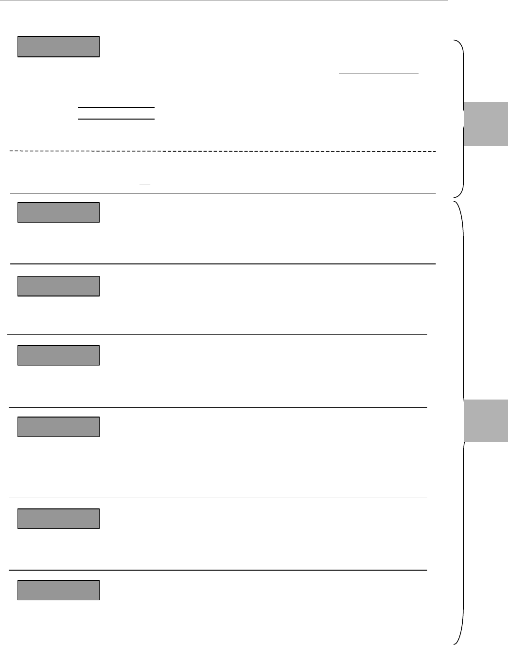
Appendix N: Install Connectors on Cables
Reference Chapter 1, Page 8 “Regulatory Information” requirements.
The following article, written by Lou Caruso of Times Microwave Systems, appears in Volume 8
Issue 5, 2000 of Telecom Exchange.
“Among the keys to success in any wireless system are the quality and reliability of the connector
installations on the coaxial cable transmission lines. And it naturally follows that the more difficult
the connectors are to install, the lower the likelihood that they will be installed correctly thus
adversely affecting the quality and reliability of the entire system.
Traditional connectors require the pin contact to be soldered to the center conductor of the coax
cable. Unfortunately, when RF transmission lines are installed outdoors as is often the case, weather
conditions may not be conducive to using soldering equipment. Wind, rain and snow all can make
soldering difficult if not impossible. If electrical power isn’t available, gas or butane fired soldering
equipment may be the only recourse and these devices typically do not generate as much heat as
electrically powered devices. Consequently, they may not do as good of a job. The physical handling
of the cable, connector pin, butane torch and solder can also be tricky (not enough hands!),
especially if there’s only one person doing the installation.
For indoor installations, such as distributed antenna systems in buildings, the installer may be
working in cramped spaces, on a ladder and in low-light conditions. How can these issues be
overcome to ensure a reliable connector installation and proper system performance?
Simplicity is the key. The connector installation process can be simplified with the use of non-solder
connectors and the correct installation tools. We have designed non-solder connectors to work with
our LMR? low-loss flexible 50-Ohm coaxial cables. These connectors may be installed under all
field installation conditions, because they use either silver or gold plated copper-beryllium spring
finger contacts that make positive contact with the center conductor and do not require soldering.
Small cable sizes, LMR-400 (3/8”) and LMR-600 (1/2”), require a crimp-style contact attachment
ring. When the cable is larger, the LMR-900-DB (5/8”) for example, a larger clamp method of
attachment is needed. Interfaces available include 7-16DIN, N, TNC and reverse polarity TNC
connectors.
Even though using non-solder connectors is simpler, there are still certain techniques that must be
used if a proper connection is to be achieved. Additionally, you must use the proper tools to get the
job done, including stripping, prepping and deburring instruments. Poorly installed connectors are
the most common cause of voltage standing wave ratio problems. Likewise, a good connection will
achieve the best RF transmission performance with a minimum of signal loss. The following
techniques will ensure a good connection and long-term reliability.

Ripwave Base Station I&C Guide Navini Networks, Inc.
176 Part #40-00047-00 Rev F v1.0 (TTA)
October 23, 2003
The typical procedure for installing the connector on cable sizes LMR-400 and LMR-600 (also is the
same procedure on DB and FR) is:
?? Flush cut the cable squarely.
?? Slide the heat shrink boot and crimp ring onto the cable. Strip the cable-end using the ST-400-EZ
or ST-600-EZ prep/strip tool by inserting the cable into End 1 and rotating the tool. Remove any
residual dielectric material from the center conductor.
?? Insert the cable into End 2 of the tool and rotate the tool to remove the plastic jacket.
?? Deburr the center conductor using the DBT-01 deburring tool.
?? Flare the braid slightly and push the connector body onto the cable until the connector snaps into
place, then slide the crimp ring forward, creasing the braid.
?? Temporarily slide the crimp ring back, and remove the connector body from the cable to trim the
excess braid at the crease line, then remount the connector and slide the crimp ring forward until
it butts up against the connector body.
?? Position the heavy duty HX-4 crimp tool with the appropriate dies (CT-400/300 tool may be
used on LMR-400) directly behind and adjacent to the connector body, and crimp the connector.
The HX-4 crimp tool automatically releases when the crimp is complete.
?? Position the heat shrink boot as far forward on the connector body as possible, without
interfering with the coupling nut and use a heat gun to form a weather tight seal.
The procedure for installing the connector on cable sizes LMR-400-LLPL and LMR-600-LLPL is
very similar with a couple of differences:
?? Flush cut the cable squarely.
?? Slide the heat shrink boot and crimp ring onto the cable. Strip the cable-end using the ST-400-EZ
or ST-600-EZ prep/strip tool by inserting the cable into End 1 and rotating the tool. Remove any
residual dielectric material from the center conductor.
?? Insert the cable into End 2 of the tool and rotate the tool to remove the plastic jacket.
?? Deburr the center conductor using the DBT-01 deburring tool.
?? Flare the braid slightly, then put a slight taper on the front edge of the aluminum-covered
dielectric by ‘rolling’ your fingers around the stripped end. (The heat shrink boot can also be
used rather than your fingers.)
?? Rotate (turn) and push the connector body with a screwing motion (to prevent the foil from
pushing back) onto the cable until the connector snaps into place. Then slide the crimp ring
forward creasing the braid.
?? Temporarily slide the crimp ring back, and remove the connector body from the cable to trim the
excess braid at the crease line, then remount the connector and slide the crimp ring forward until
it butts up against the connector body.
?? Position the heavy duty HX-4 crimp tool with the appropriate dies (CT-400/300 tool may be
used on LMR-400-LLPL) directly behind and adjacent to the connector body, and crimp the
connector. The HX-4 crimp tool automatically releases when the crimp is complete.
?? Position the heat shrink boot as far forward on the connector body as possible, without
interfering with the coupling nut and use a heat gun to form a weather tight seal.

Navini Networks, Inc. Ripwave Base Station I&C Guide
Part #40-00047-00 Rev F v1.0 (TTA) 177
October 23, 2003
For installing the ‘EZ’ connectors on LMR-900-DB, FR and LLPL cables and larger, the process is
as follows:
?? Flush cut the cable squarely.
?? Slide the backnut and gasket onto the cable.
?? Strip the cable-end using the EZ prep/strip tool by inserting the cable into the proper end of the
tool (note that only one strip is needed).
?? Slide the gland washer on the end of the cable and over the braid (being careful not to disturb the
braid) until it rests on the end of the cable jacket.
?? Spread the braid over the gland washer.
?? Slide the collar over the foil.
?? Push the ‘spring finger’ end of the connector pin assembly into the hollow center conductor.
?? Bring up the backnut and gasket.
?? Screw the connector head onto the backnut and tighten with proper size wrenches until the
gasket is almost fully compressed.”
Table N1: Reference Chart Showing ‘EZ’ Connectors For Use with LMR, DB & FR Cables
LMR? FR
DB Interface Description Part
Number Coupling
Nut Inner
Contact Outer
Contact
400 N Male Straight
Plug EZ-400-
NMH Hex Spring
Finger Crimp
400 N Female Straight
Jack EZ-400-NF NA Spring
Finger Crimp
400 N Female Bulkhead
Jack EZ-400-
NF-Bh NA Spring
Finger Crimp
400 TNC Male Straight
Plug EZ-400-
TM Knurl Spring
Finger Crimp
400 TNC Male Reverse
Polarity EZ-400-
TM-RP Knurl Spring
Finger Crimp
400 TNC
Female Reverse
Polarity EZ-400-
TM-RP Knurl Spring
Finger Crimp
400 UHF Male Straight
Plug EZ-400-
UM Knurl Spring
Finger Crimp
600 N Male Straight
Plug EZ-600-
NMH Hex Spring
Finger Crimp
600 N Male Right
Angle EZ-600-
NMH-RA Hex Spring
Finger Crimp
600 N Female Straight
Jack EZ-600-NF NA Spring
Finger Crimp
600 N Female Bulkhead
Jack EZ-600-
NF-BH NA Spring
Finger Crimp
600 TNC Male Straight
Plug EZ-600-
TM Knurl Spring
Finger Crimp
600 TNC Male Reverse
Polarity EZ-600-
TM-RP Knurl Spring
Finger Crimp
600
TNC
Reverse
EZ
-
600
-
NA
Spring
Crimp

Ripwave Base Station I&C Guide Navini Networks, Inc.
178 Part #40-00047-00 Rev F v1.0 (TTA)
October 23, 2003
LMR? FR
DB Interface Description Part
Number Coupling
Nut Inner
Contact Outer
Contact
Female Polarity TM-RP Finger
600 UHF Male Straight
Plug EZ-600-
UM Knurl Spring
Finger Crimp
600 716 DIN
Male Straight
Plug EZ-600-
716-MH Hex Spring
Finger Crimp
900 N Male Straight
Plug EZ-900-
NMC Hex Press Fit Clamp
900 N Female Straight
Jack EZ-900-
NFC NA Press Fit Clamp
900 716 DIN
Male Straight
Plug EZ-900-
716MC Hex Press Fit Clamp
900 716 DIN
Male Right
Angle EZ-900-
716-MCRA
Hex Press Fit Clamp
900 716 DIN
Female Straight
Jack EZ-900-
716-FC NA Press Fit Clamp
900 7/8 EIA Straight
Plug EZ-900-
78EIA NA Press Fit Clamp
1200 N Male Straight
Plug EZ-1200-
NMC Hex Press Fit Clamp
1200 N Female Straight
Jack EZ-1200-
NFC NA Press Fit Clamp
1200 716 DIN
Male Straight
Plug EZ-1200-
716MC Hex Press Fit Clamp
1200 716 DIN
Female Straight
Jack EZ-1200-
716-FC NA Press Fit Clamp
1200 7/8 EIA Straight
Plug EZ-1200-
78EIA NA Press Fit Clamp
1700 N Male Straight
Plug EZ-1700-
NMC Hex Press Fit Clamp
1700 N Female Straight
Jack EZ-1700-
NFC NA Press Fit Clamp
1700 716 DIN
Male Straight
Plug EZ-1700-
716MC Hex Press Fit Clamp
1700 716 DIN
Female Straight
Jack EZ-1700-
716-FC NA Press Fit Clamp
Table N2: Reference Chart Showing ‘EZ’ Connectors For Use with LMR LLPL Cables
LLPL Interface Description Part
Number Coupling
Nut Inner
Contact Outer
Contact
400 N Male Straight
Plug EZ-400-
NMH-PL Hex Spring
Finger Crimp
600 N Male Straight
Plug EZ-600-
NMH-PL Hex Spring
Finger Crimp
900 N Male
Straight
EZ
-
900
-
Hex Press Fit Clamp

Navini Networks, Inc. Ripwave Base Station I&C Guide
Part #40-00047-00 Rev F v1.0 (TTA) 179
October 23, 2003
LLPL Interface Description Part
Number Coupling
Nut Inner
Contact Outer
Contact
Plug NMC-PL
900 N Female Straight
Jack EZ-900-
NFC-PL NA Press Fit Clamp
1200 N Male Straight
Plug EZ-1200-
NMC-PL Hex Press Fit Clamp
1200 N Female Straight
Jack EZ-1200-
NFC-PL NA Press Fit Clamp
Table N3: Reference Chart Showing the Proper Tools for Use with ‘EZ’ Connectors
LMR?
LMR?-FR
LMR?-DB
LMR?-LLPL
‘EZ’
Connector
Type
Strip/Prep
Tool Deburr
Tool Crimp
Handle Crimp
Dies Wrenches
400 (3/8”) Crimp ST-400EZ DBT-01 HX-4
CT-
400/300
Y1719
Included
w/Handle
N/A
600 (1/2”) Crimp ST-600EZ DBT-01 Hex-4 Y1720 N/A
900-DB
(5/8”) Clamp ST-
900/1200C
N/A N/A N/A WR-900 WR-900
1200-DB
(7/8”) Clamp ST-
900/1200C
N/A N/A N/A WR-1200A WR-
1200B
1700-DB
(1-1/4”) Clamp ST-1700C N/A N/A N/A WR-1700 WR-1700
All outdoor installations should be weatherproofed with either a standard weatherproofing kit such
as the Times WK-2 kit or a cold shrink kit, also available from Times. Times LMR? coax cables are
low loss, flexible and non-kinking, unlike corrugated coax cables, which are much less flexible and
prone to kinking. Times Microwave Systems offers a complete range of LMR? cables to suit every
possible type of installation and need:
?? LMR? – Low loss coax, flexible and non-kinking; suitable for general outdoor use such as
jumpers, rooftops and short tower runs.
?? LMR? DB – Watertight outdoor cable; designed for tower feeder runs, jumpers and rooftops
applications; uses the same connectors as LMR? cable.
?? LMR? FR – Riser rated (UL/CSA listed); fire retardant; employs a low smoke non-halogen
polyolefin jacket; for use in vertical riser/access shafts – unoccupied building spaces or anywhere
that fire retardance is needed; uses the same connectors as LMR? cable.
?? LMR? – LLPL – Plenum rated (UL/CSA listed); for in-building runs; can be used in open air
handling spaces such as above drop ceilings and air plenums; flame retardant and low smoke
generating design; uses special ‘EZ’ connectors.

Ripwave Base Station I&C Guide Navini Networks, Inc.
180 Part #40-00047-00 Rev F v1.0 (TTA)
October 23, 2003