Cisco Systems BTS-R3 Broadband Data BTS User Manual chpt 2d 40 00047 05 F I C TTA
Cisco Systems, Inc Broadband Data BTS chpt 2d 40 00047 05 F I C TTA
Contents
Manaul 5
Navini Networks, Inc. Ripwave Base Station I&C Guide
Chapter 2d
Part #40-00047-05 Rev F v1.0 (TTA) 65
October 23, 2003
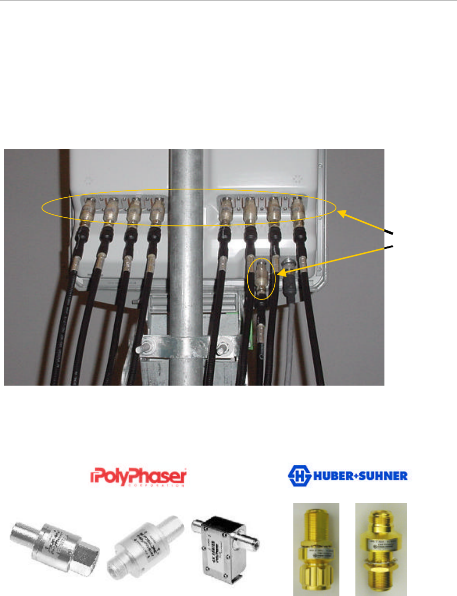
The RFS has ten cable connectors on the bottom of the unit. Eight are antenna connections, with
the connectors alternately numbered from right to left as shown in Figure 33. The two connectors
in the middle are for antenna calibration and data/DC power connections. Install surge protectors
on nine (9) of the RFS connectors – the eight antenna connectors and the calibration connector.
The surge protectors must be installed directly to the RFS to provide protection for the antenna
elements. Torque the surge protectors to 20-24 inch-pounds.
Figure 33: PolyPhaser PSX-ME Surge Protectors at the Antenna (RF and Cal Cables)
Figure 34: Surge Protectors
PSX-ME PSX DGXZ+06NFNF-A3406.17.0012 3406.17.0009
PSX-MEPSX-ME PSXPSX DGXZ+06NFNF-A3406.17.00123406.17.0012 3406.17.00093406.17.0009
6 2 5 18 4 7 3
Surge
Protectors
6 2 5 18 4 7 3
Surge
Protectors
Ripwave Base Station I&C Guide Navini Networks, Inc.
Chapter 2d
66 Part #40-00047-05 Rev F v1.0 (TTA)
October 23, 2003
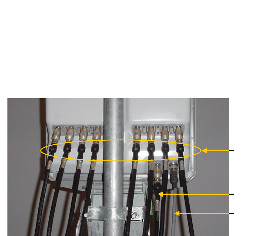
Install Cables Between the RFS & BTS
Connect all of the cables – the eight antenna cables, the calibration cable and the data/power
cable – to the surge protectors on the RFS. For ease of installation, install the cables from the
inside out. Ensure that the proper cable is connected to the proper antenna (Figure 35). Torque
the RF cable connectors to 20-24 inch-pounds.
Figure 35: Completed Cable Installation at the Antenna
Install Grounding Kit on Cables
Install grounding kit wire connections on the eight (8) RFS cables and the one (1) CAL cable per
the instruction sheet that comes with the grounding kit. Install the grounding wire in a position
on the cable so that it can be attached to the ground buss bar that is mounted close to the RFS.
More than one ground buss bar may be installed in the system, depending on the length of the
cable run. Reference the Regulatory Information in Chapter 1, Page 8.
6 2 5 18 4 7 3
Calibration
Cable
Data/Power
Cable
RF Cables
6 2 5 18 4 7 3
Calibration
Cable
Data/Power
Cable
RF Cables
Navini Networks, Inc. Ripwave Base Station I&C Guide
Chapter 2d
Part #40-00047-05 Rev F v1.0 (TTA) 67
October 23, 2003
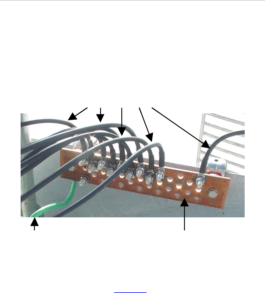
Connect Ground Wires to the Ground Buss Bar
Connect the ground wires on the cables to the ground buss bar using the hardware supplied with
the grounding kit. Connect the ground stud on the RFS to the ground buss bar. Use a ¼-inch
terminal lug to connect the ground wire to the ground stud on the RFS. Connect the ground buss
bar to earth ground. An example is shown in Figure 36.
Figure 36: RFS Grounding
Test the RFS & Cables
Test the RFS and the eight (8) cables using Appendix O, the RFS System Test Form. Record the
results in the form. For this test, use the cable connectors that will be attached to the BTS.
Include the jumpers and all surge protectors.
Ground Buss Bar
Ground Wires
Earth Ground Ground Buss Bar
Ground Wires
Earth Ground
Ripwave Base Station I&C Guide Navini Networks, Inc.
Chapter 2d
68 Part #40-00047-05 Rev F v1.0 (TTA)
October 23, 2003
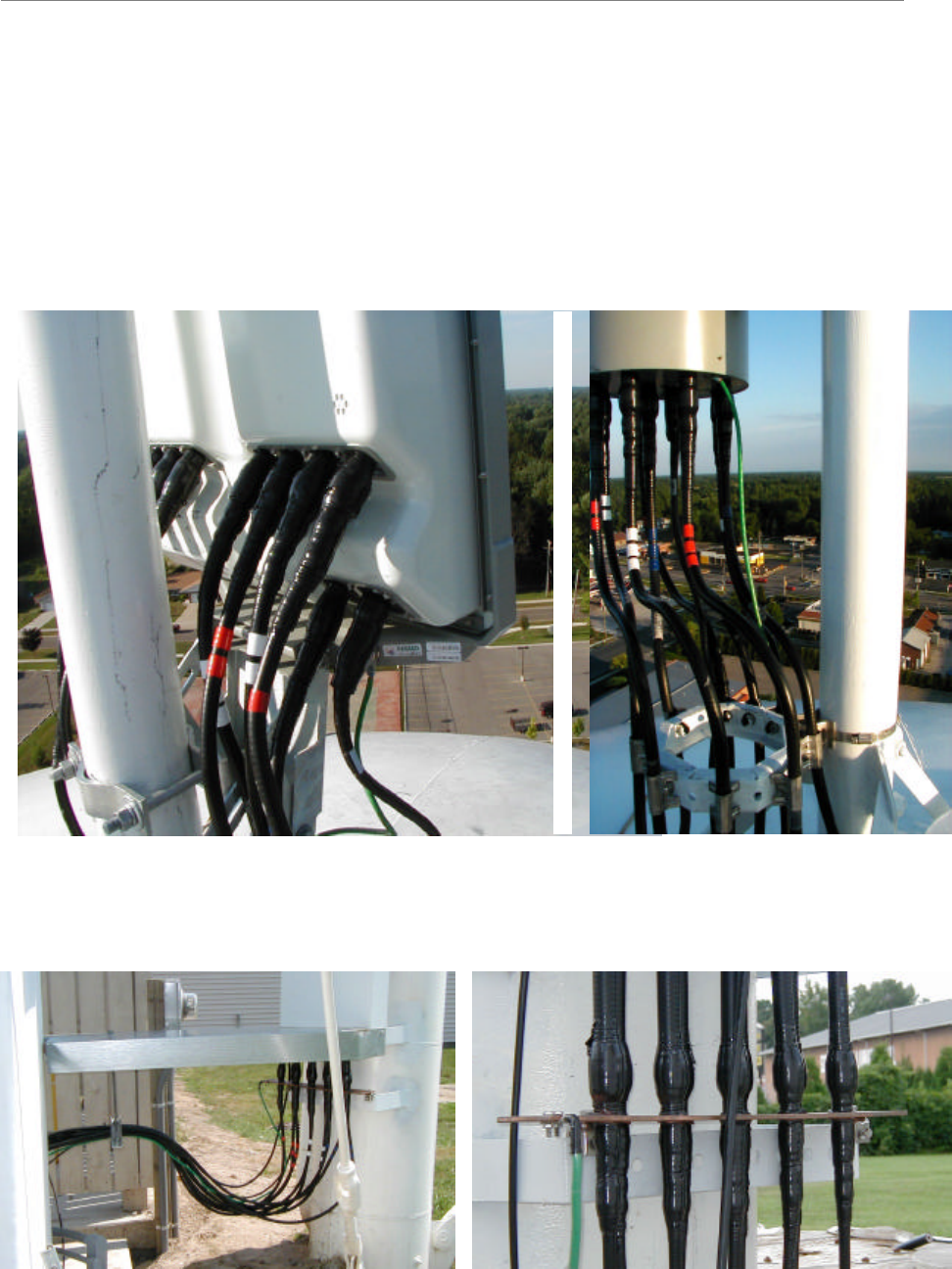
Weatherize the RFS Cable Connectors
Weatherize all ground wire connections exposed to weather using electrical tape and butyl
mastic tape. Follow the instructions supplied with the weatherproofing kit. Examples are shown
in Figure 37 and 38.
Figure 37: Weatherizing RFS Connectors Cables
Figure 38: Weatherizing Ground Wires