Cisco Systems BTS-R3 Broadband Data BTS User Manual chpt 2e 40 00047 06 F I C TTA
Cisco Systems, Inc Broadband Data BTS chpt 2e 40 00047 06 F I C TTA
Contents
Manual 6
Navini Networks, Inc. Ripwave Base Station I&C Guide
Chapter 2e
Part #40-00047-06 Rev F v1.0 (TTA) 69
October 23, 2003
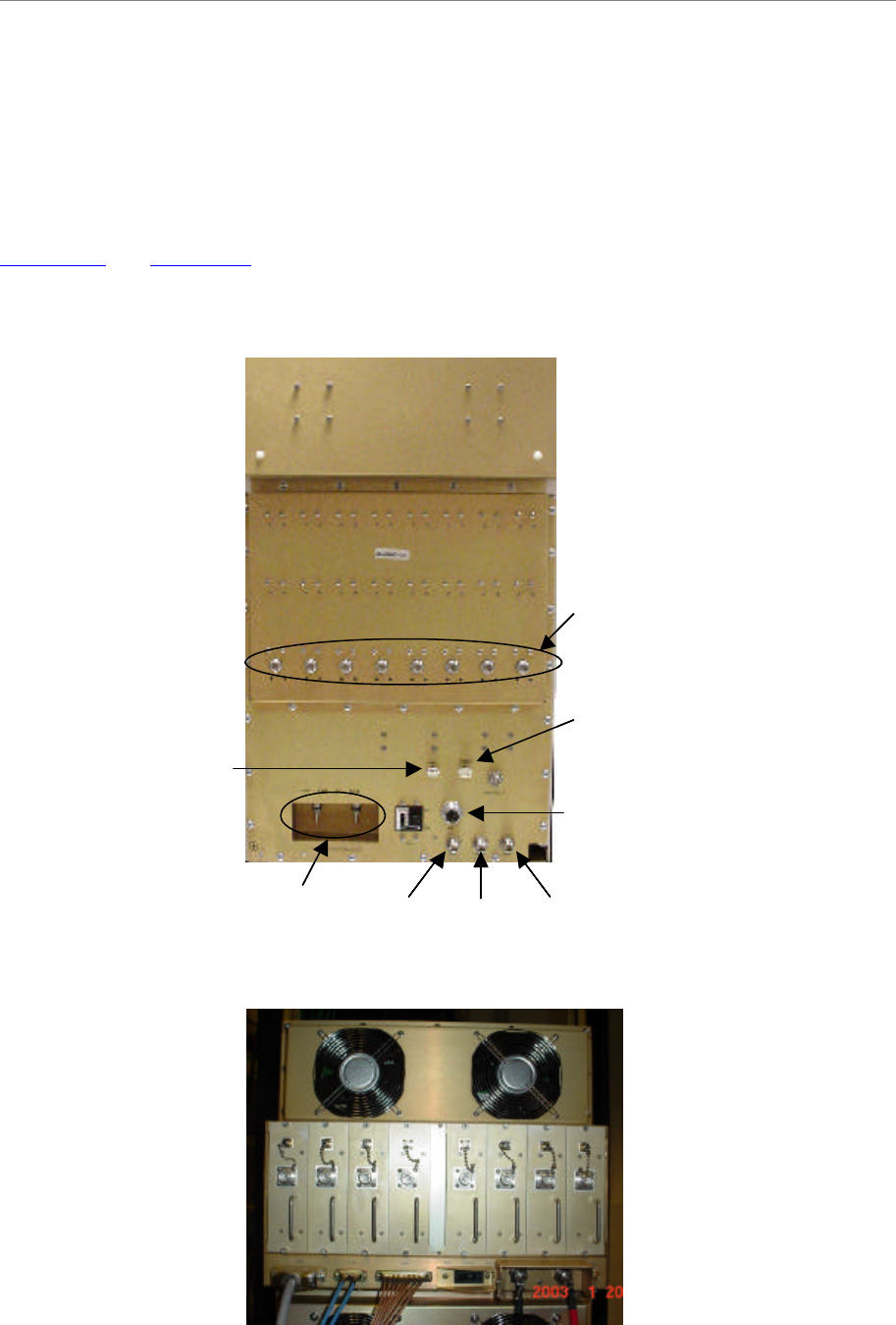
Connect RF Cables & Alarms to BTS
Connect all of the cables to the BTS. The connection points are shown in Figures 39, 40, 41, and
42. Torque the cable connectors to 20-24 inch-pounds. If applicable, connect the cabinet alarm
connector and Battery Backup connector (Cabinet Alarm and BBU) to the back of the chassis.
More information on connecting alarms, rectifiers, and battery backup equipment are provided in
Appendix P and Appendix J, respectively.
Figure 39: Combo Chassis Rear View
Figure 40: Split Chassis RF/PA Shelf Rear View
Cabinet
Alarms
Data/Power
GPS 2CAL GPS 1DC Power
RF Cables
Battery
Backup
Unit
(BBU)
Alarms
Cabinet
Alarms
Data/Power
GPS 2CAL GPS 1DC Power
RF Cables
Battery
Backup
Unit
(BBU)
Alarms
Ripwave Base Station I&C Guide Navini Networks, Inc.
Chapter 2e
70 Part #40-00047-06 Rev F v1.0 (TTA)
October 23, 2003
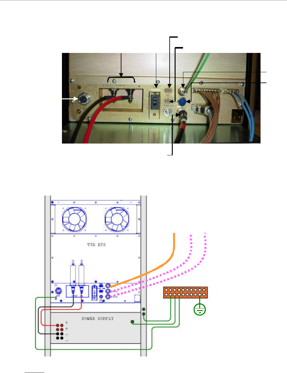
Figure 41: Split Chassis Digital Shelf Rear View
Figure 42: TTA Chassis Digital Shelf Rear View
NOTE: Do not ground the negative terminal of the rectifier for the TTA installation.
Power
Connectors ON/OFF
Battery Backup Connector
Cabinet Alarms Connector
Data/Power
Cable Connector
GPS 1
GPS 2
Cal Cable
Power
Connectors ON/OFF
Battery Backup Connector
Cabinet Alarms Connector
Data/Power
Cable Connector
GPS 1
GPS 2
Cal Cable
Cal Cable
GPS-1
GPS-2
Cal Cable
GPS-1
GPS-2
Cal Cable
GPS-1
GPS-2
Navini Networks, Inc. Ripwave Base Station I&C Guide
Chapter 2e
Part #40-00047-06 Rev F v1.0 (TTA) 71
October 23, 2003
Omni Antenna
The RFS Omni antenna is installed on a structure, such as a tower or a pole, which is defined in
the site survey and design. Following are the steps to complete the installation of the panel
antenna. Refer to the Regulatory Information in Chapter 1, Page 8 prior to installing.
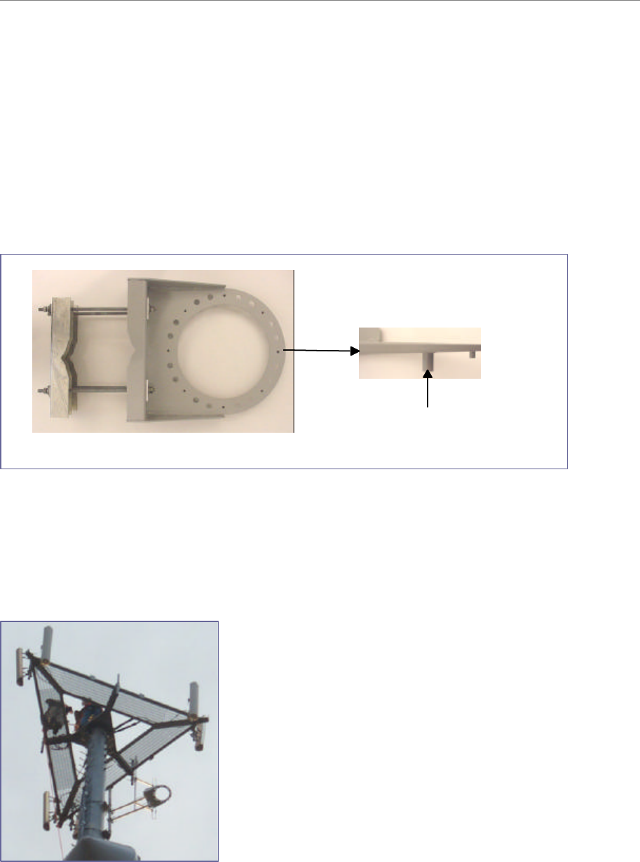
Assemble the Antenna Mount per the instructions that come with it (Figure 43). Use a compass
to determine which direction is true East (incorporating declination angle - see Figure 31).
Figure 43: Omni Antenna Mount
Position the Antenna Mount in a direction to provide accessibility to the RFS after it is installed.
Position and install the Antenna Mount on the mounting structure so that any one of the eight
mounting hole pins is facing East. Tighten the Antenna Mount hardware to secure it to the
structure (Figure 44).
Figure 44: Secured Omni Antenna Mount
Mounting Hole Pin
Ripwave Base Station I&C Guide Navini Networks, Inc.
Chapter 2e
72 Part #40-00047-06 Rev F v1.0 (TTA)
October 23, 2003
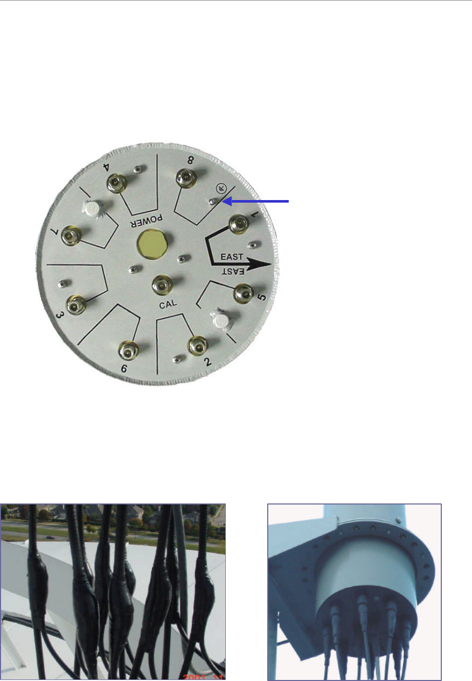
Sweep the RFS antenna inputs for dB loss. Record all results for later calculations. Position the
RFS on the Antenna Mount, ensuring that the arrow on the bottom of the Antenna Mount faces
true East. Secure the RFS antenna to the Antenna Mount (Figure 45). Install surge protectors on
the 8 antenna and 1 cal connectors.
Figure 45: Omni Ground Stud
Connect the eight antenna cables, cal cable, and Data/Power cable to the RFS antenna. Attach the
ground wire to the ground stud. Install grounding kits from RF cables to buss bars. Sweep the
antenna and cables from the RF cable connectors that attach to the BTS. Record all
measurements. Weatherize all connections (Figure 46).
Figure 46: Weatherized Connectors
Ground StubGround Stub
Navini Networks, Inc. Ripwave Base Station I&C Guide
Chapter 2e
Part #40-00047-06 Rev F v1.0 (TTA) 73
October 23, 2003
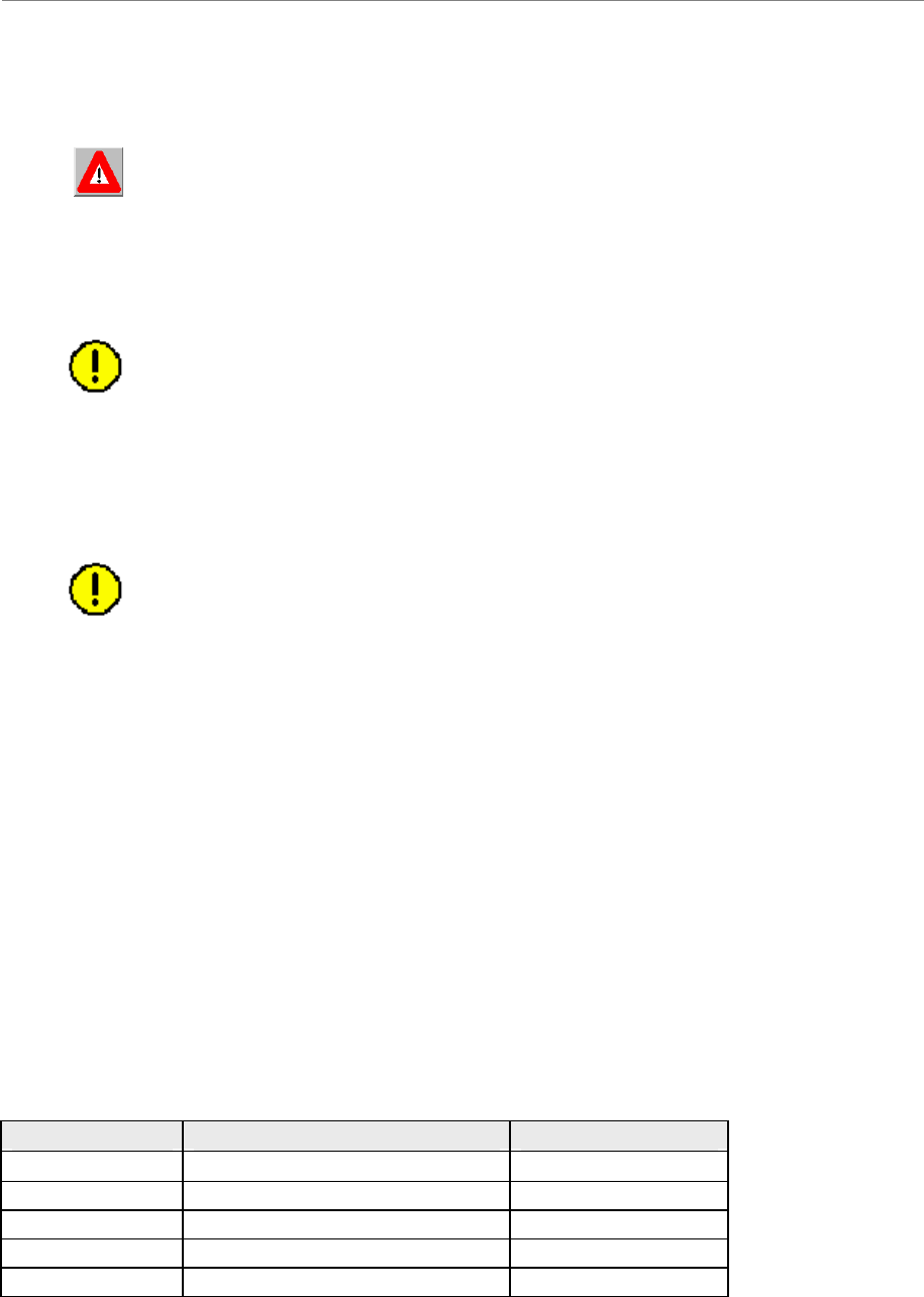
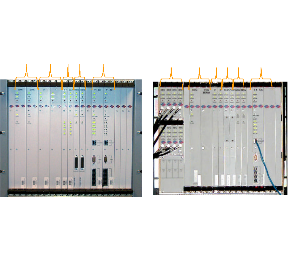
Verify Installed Circuit Cards
WARNING! Ensure that power to the BTS chassis is off before installing the
circuit cards or any of the RF Power Amplifiers in the chassis.
FUSES ARE NOT FIELD-REPLACEABLE. In case of need to replace a fuse on a CHP (F1),
CC (F33, F17-32), SYN (F3), MDM (F1) or PA (F1) contact Navini Networks Technical
Support
CAUTION! For continued protection against risk of fire, replace only with the
same type and rating of fuse.
ATTENTION! Pour ne pas compromettre la protection contre les risques
d’incendie, remplacer par un fusible du même type et des mêmes caractéristiques
nominales.
CAUTION! - Please contact Navini Technical support before attempting to
exchange cards between chassis of different type and frequency to verify
compatibility.
The circuit cards, including the RF/PA cards, normally come seated in the BTS chassis. If they
are already installed, verify that the correct cards are placed and seated properly. The RF/PA
modules may be installed in any position on the top (RF) shelf. For the Digital shelf, refer to
Figure 47 for correct card placement. Table 4 describes the name of each type of card in the
Digital shelf.
Tighten the screws to secure the RF/PAs into the RF shelf. For the circuit cards, follow the
markings on the backplane for the position of each card in the Digital shelf. Make sure the
ejectors on all cards are engaged in the chassis. Figure 46 represents a fully populated Digital
shelf. If the BTS is not fully populated, blank panels are installed to fill in the empty card space.
They are also used to fill in the empty space between the circuit cards and the end of the cabinet.
Table 4: Digital Card Names
Abbreviation Card Name Number of Cards
SYN Synthesizer 1 or 2
IF Intermediate Frequency Always 2
CHP Channel Processor Always 2
MDM Modem Always 2
CC Communications Controller 1 or 2
Ripwave Base Station I&C Guide Navini Networks, Inc.
Chapter 2e
74 Part #40-00047-06 Rev F v1.0 (TTA)
October 23, 2003
Figure 47: Digital Shelf
Base Station Installation Certification
When the installation of the equipment is complete, the Base Station Installation Certification
form needs to be completed and signed off by both the installer and the customer. A copy of this
form may be found in Appendix T.
SYN
IF
CHP
MDM
CC
Combo/Split Chassis
SYN
IF
CHP
MDM
CC
RFC
TTA
SYN
IF
CHP
MDM
CC
Combo/Split Chassis
SYN
IF
CHP
MDM
CC
RFC
TTA