Cisco Systems BTS-R3 Broadband Data BTS User Manual chpt 2c 40 00047 04 F I C TTA
Cisco Systems, Inc Broadband Data BTS chpt 2c 40 00047 04 F I C TTA
Contents
Manual 4
Navini Networks, Inc. Ripwave Base Station I&C Guide
Chapter 2c
Part #40-00047-04 Rev F v1.0 (TTA) 61
October 23, 2003
Install the RFS
Check all regulatory standards (refer to Chapter 1, Page 8 “Regulatory Information”) prior to
installation. Now that the BTS is in place, the RFS is readied for installation. Follow the Panel or
Omni Antenna information and procedures below. Reference the specifications in Appendix H.
Panel Antenna
The RFS Panel antenna is installed on a structure, such as a tower or a pole, which is defined in
the site survey and design. Following are the steps to complete the installation of the panel
antenna.
Verify RFS Operation
Verify proper operation of the RFS before installation. Test the transmit and receive path of each
antenna in the RFS per Appendix S, and using the RFS System Test Form in Appendix O.
Set the Downtilt
Check the engineering study for the required downtilt of the antenna. The panel antenna has 6o of
fixed electrical downtilt but it can be mechanically adjusted for an uptilt of 0 to 10o. As a result,
the main lobe of the beam can be pointed between 4 degrees above and 6 degrees below the
horizon.
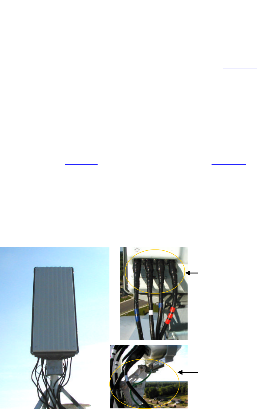
Figure 28: Panel Antenna Elements
Weatherized
connectors
Mounting
Bracket
(downtilt
adjustment)
Weatherized
connectors
Mounting
Bracket
(downtilt
adjustment)
Ripwave Base Station I&C Guide Navini Networks, Inc.
Chapter 2c
62 Part #40-00047-04 Rev F v1.0 (TTA)
October 23, 2003
Omni Antenna
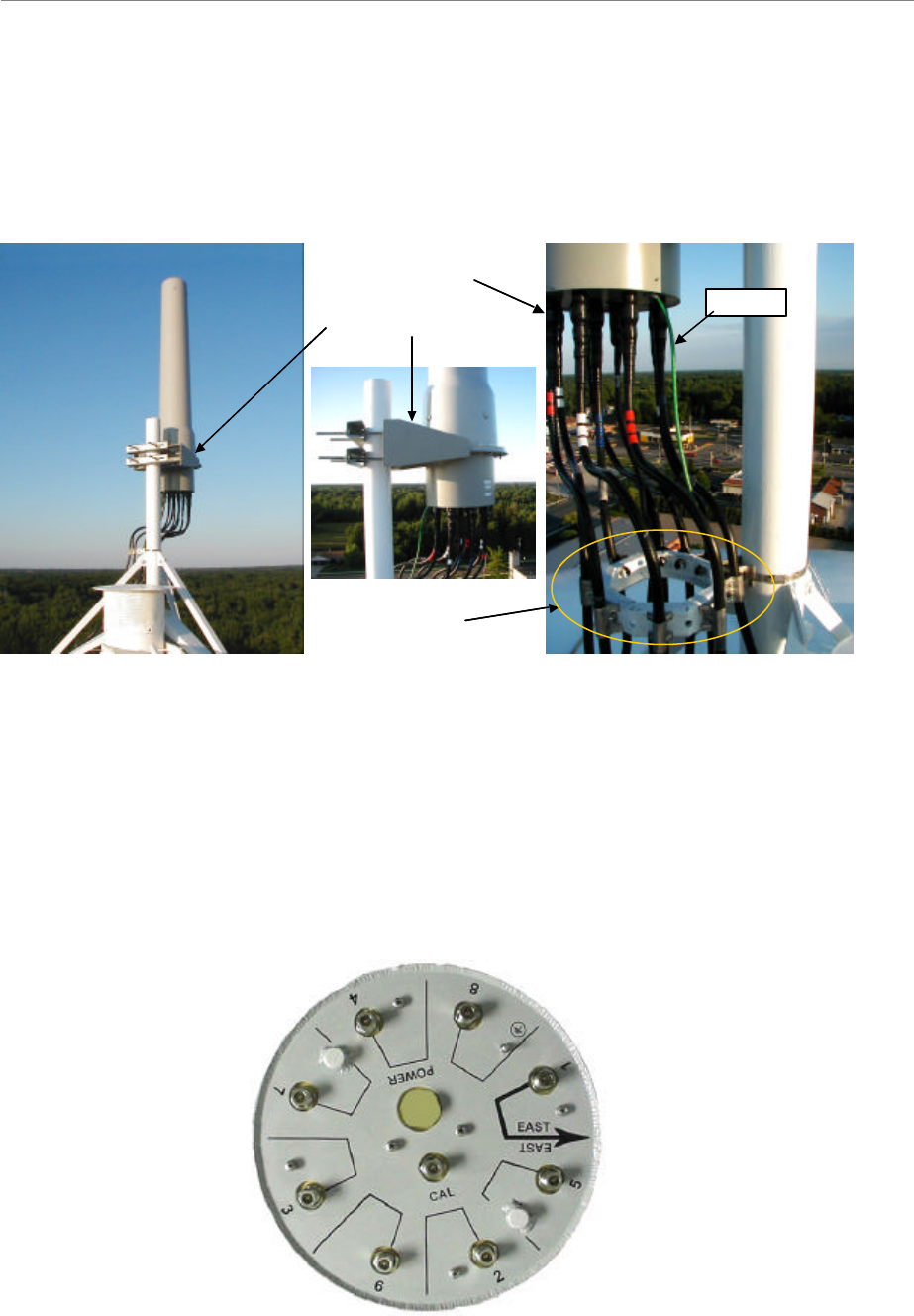
An Omni antenna has 2 degrees of fixed electrical downtilt
Figure 29: Omni Antenna Elements
Set the Azimuth
Position the RFS on the mounting pole or structure, ensuring that the antenna is pointing in the
proper azimuth direction determined by the engineering study. For an omni, the first antenna
element must face East (Figure 30).
Figure 30: Bottom of an Omni Antenna Showing Correct Orientation
Make sure that
this arrow
points due East
Make sure that
this arrow
points due East
Weatherized
connectors
Mounting
bracket
Ground
Cable Hoist
Weatherized
connectors
Mounting
bracket
Ground
Cable Hoist
Navini Networks, Inc. Ripwave Base Station I&C Guide
Chapter 2c
Part #40-00047-04 Rev F v1.0 (TTA) 63
October 23, 2003
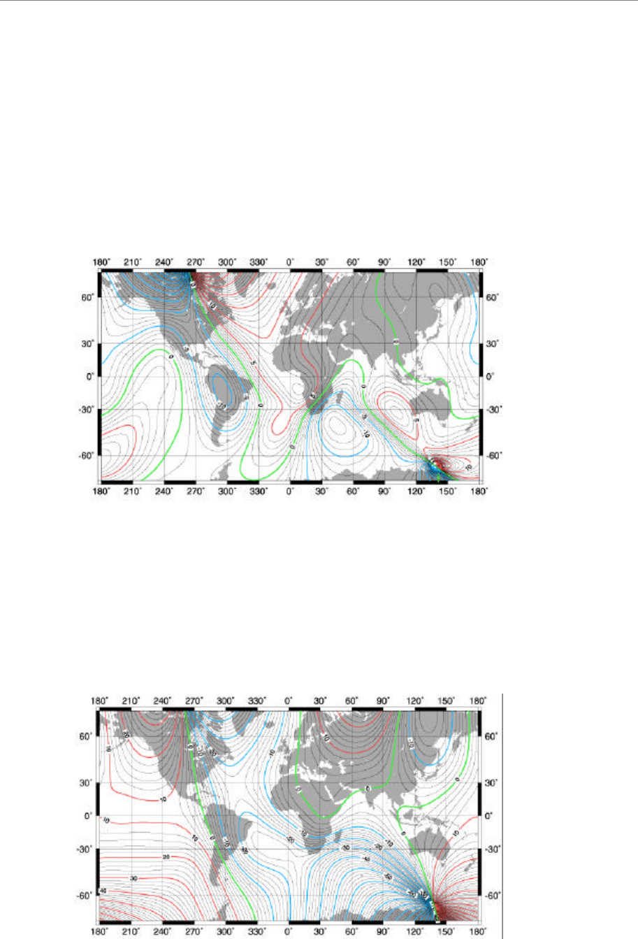
The azimuth direction is stated in degrees from true North. Use the diagram shown in Figure 31
to determine the declination angle for your location. Add or subtract the declination angle from
magnetic North to obtain true North.
Tighten the four nuts on each of the two antenna mounting brackets to secure the RFS to the
mounting pole. Use a compass to check the direction from the center of the panel (this is
magnetic North). Be sure that you are using a compass calibrated for the geographical region
where you are. There are five such regions and a compass calibrated for one of them will not
work properly in the others.
Figure 31: Declination Angle in Degrees (Year 2000)
Since this is not the year 2000 anymore, you will want to check this reference map to learn how
your magnetic declination shifts from year to year. Notice that the map measures annual shifts in
minutes. Since it takes 60 minutes to equal 1 degree, if you notice that your location has a
declination shift of 5 minutes per year, this means it will be another 12 years before your
declination adjustment changes by one whole degree. The following web site provides more
details on how to use these charts: http://www.thecompassstore.com/decvar.html
Figure 31a: Annual Change in Magnetic Declination
Ripwave Base Station I&C Guide Navini Networks, Inc.
Chapter 2c
64 Part #40-00047-04 Rev F v1.0 (TTA)
October 23, 2003
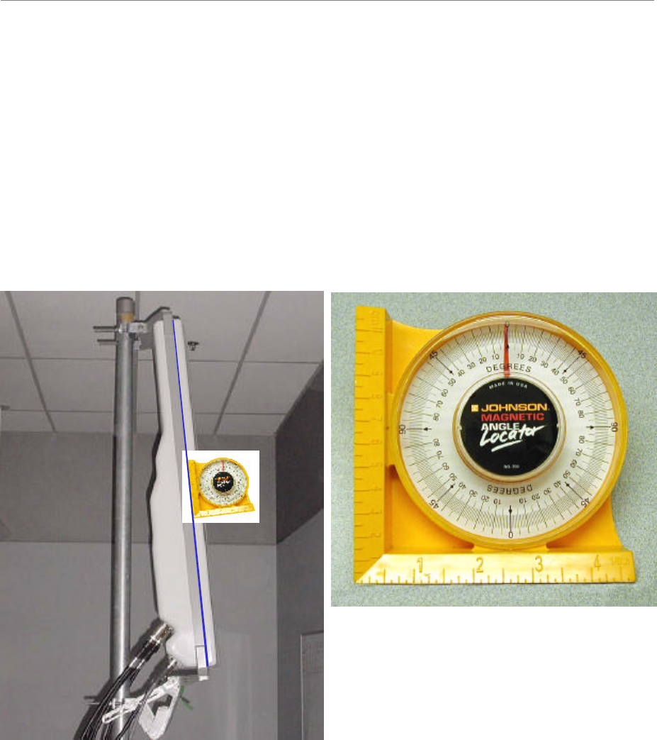
Verify the Downtilt
Using an inclinometer (Figure 32), check the downtilt of the RFS antenna. If required, adjust the
angle using the downtilt adjustment brackets. Be sure to include any electrical uptilt or downtilt
built into the antenna in the setting.
Tighten the mounting hardware to secure the RFS in the proper position. Recheck the downtilt
angle again to verify proper position. Repeat the procedure for all other antennas that are
installed in the system. Ensure that they are mounted in the proper direction and with the correct
downtilt angle.
Figure 32: Measuring Antenna Downtilt
Install Surge Protectors
If lightning protection is required, as determined by the customer, the power/data lightning
arrestors must comply with UL497. Cables, such as the RF and power/data cables, in excess of
140 feet in length must have protective devices installed that are UL497A or UL497B listed.
For accurate results, align the
inclinometer against the metal frame
on the side of the panel antenna, which
is guaranteed to be parallel to the
antenna elements
For accurate results, align the
inclinometer against the metal frame
on the side of the panel antenna, which
is guaranteed to be parallel to the
antenna elements