Cisco Systems BTS-R3 Broadband Data BTS User Manual chpt 2a 40 00047 02 F I C TTA
Cisco Systems, Inc Broadband Data BTS chpt 2a 40 00047 02 F I C TTA
Contents
Manual 2

Navini Networks, Inc. Base Station I&C Guide
Chapter 2a
Part #40-00047-02 Rev F v1.0 (TTA) 41
October 23, 2003
Chapter 2: Installation
Pre-installation
As was shown in Figure 4, prior to installing the equipment a number of planning and acquisition
activities take place. The installation itself takes only about 2 days. The I&C crew may or may
not be involved with all the pre-installation activities. Of these, they are most likely to be
involved in the Site Candidate Evaluation, the gathering of data for the Interference Analysis,
and the Antenna Power & Cable Selection step of the process.
Project Plan
A Project Plan is a document that lays out the work to be done, the objectives of the project, the
schedule, resources required, and so forth. If Navini is performing the I&C activities, a Project
Manager is assigned. The Project Manager prepares the Project Plan and shares it with the
Navini and customer teams.
An example of a written Statement of Work (SOW), Responsibility Assignment Matrix (RAM),
and Work Breakdown Structure (WBS) for installation and commissioning are provided in
Appendices A, B, and C. These types of documents may be used in negotiating work between
companies and contractor services.
Coverage Prediction Map
Early in the planning of deployment of Ripwave Base Station equipment, an RF Engineer will go
through the process of studying the RF environment of the candidate sites that the customer has
identified. Readings are taken and analyzed at each site in order to predict what range of
coverage can be expected from installing a Base Station at the site.
Coverage predictions account for both Base Station performance and Marketing objectives with
the service itself. The customer accomplishes the latter as part of the decisions concerning site
selection.

Ripwave Base Station I&C Guide Navini Networks, Inc.
Chapter 2a
42 Part #40-00047-02 Rev E v1.0 (TTA)
October 23, 2003
Site Candidate Evaluation
Often Technicians will be very comfortable with either the networking side or the wireless side
of the system, but not usually both. To evaluate a potential install site, a form helps ensure all
aspects of the site have been considered. Information about the site is recorded on the form.
Since each site is unique, the form helps to ensure nothing is taken for granted or assumed about
the installation site for the Ripwave equipment.
A copy of this form may be found in Appendix D. It includes places to capture the logistics of
the site, tower or rooftop mount possibilities, GPS coordinates, type of antenna to be installed,
whether or not an outdoor enclosure is provided, power availability, distance between connection
points, ventilation, a place for drawings from every angle, etc. It is from this information that the
site will be designed, then installed to plan.
Interference Analysis
As part of deploying a Ripwave Base Station, the Field Service Engineer must collect critical
information from the site. The data is provided to the RF Engineering personnel, who can then
evaluate the Radio Frequency (RF) conditions. The RF Engineer analyzes the data for existing
interference from other sources, and takes that into account when creating the coverage
prediction map.
The RF Engineer, in turn, supplies to the Field Service Engineer at the site valuable data
parameters and configuration information unique to each system and each site. In addition to
coverage, though, the interference analysis also helps to predict the quality of service, the power
requirements to get above the noise floor, and other expectations regarding the site.
This study helps Navini and the customer decide which type of system (frequency) and antenna
(panel or omni) will provide the best results. To collect the data the on-site Technician or Field
Engineer performs an Interference Sweep Procedure (Appendix E) and supplies that data to the
RF Engineer(s). Refer to Appendix F for instructions on using the sweep tool.
Site Selected & Designed
After evaluating the potential sites and the coverage prediction, the customer must select the
specific site where the Base Station is to be deployed. The site must be carefully blueprinted to
prepare for equipment ordering and installation. Navini can supply specifications and drawings
to help the customer design the site. Refer to Appendices G, H, I, J, and K for BTS
Specifications, RFS Data Sheets, BTS Outdoor Enclosures Manufacturers, Rectifier/Battery
Backup Manufacturers, and a sample Base Station drawing. Check all regulatory standards (refer
to Chapter 1, Page 8 “Regulatory Information”) prior to installation.

Navini Networks, Inc. Ripwave Base Station I&C Guide
Chapter 2a
Part #40-00047-02 Rev F v1.0 (1.20) 43
October 9, 2003
Network Architecture Plan
The IP Networking community involved in the project, both from Navini and the customer, often
work together to analyze and plan how the Ripwave system will be integrated into the
customer’s network. Of course, they are looking for efficient operation of the system and
seamless integration. They have to plan the traffic routing, IP addressing, protocol compatibility,
and so forth.
Antenna Power & Cable Selection
The size and type of cable used to install the Base Station affect power loss and calibration range
for the transmitter and receiver. It is at this point in the process that the specific cable
manufacturer, type of cable, and cable size must be determined. A complete procedure and tool
are explained in Appendix L. Refer, also, to Chapter 1, Page 8 “Regulatory Information” for
FCC warning regarding RF, and UL and NEC/CEC information regarding cable length and
connectors. All BTS and RF shelf Coax and Digital cables between the Digital and RF Shelves
are 60 inches in length. Physical distance between Digital and RF Shelves will always be less
than the cable length.
Bill of Materials
The customer has to generate the Bill of Materials (BoM) - the actual equipment order to be
manufactured and shipped to the installation site. Navini can provide part numbers and ordering
information, as well as recommendations and other details that will assist customers in the
correct placement of orders. There is a sample Bill of Materials in Appendix M.
Acquire Materials
Once ordered, the customer ensures that everything required for installing the Base Station is
secured and at the deployment site.
Confirm Backhaul Connection, EMS Server & FTP Server, Input
Power & Grounding at Site
The Backhaul connection for the Ripwave Base Station consists of up to two (2) Ethernet cable
connections with RJ-45 connectors for each BTS installed, OR, up to eight (8) T1 connections
with RJ-48 connectors for each BTS. The quantity of each connection will depend on the site
requirements. These connections need to be made available before installation begins. Refer to
the Regulatory Information in Chapter 1, Page 8 regarding backhaul connections, power and
grounding.

Ripwave Base Station I&C Guide Navini Networks, Inc.
Chapter 2a
44 Part #40-00047-02 Rev E v1.0 (TTA)
October 23, 2003
The customer’s EMS Server and FTP Server should be put into place prior to the installation
crew’s arrival at site. If the customer’s EMS Server is not available until after installation begins,
the crew can typically use a laptop to perform initial configuration. The FTP Server, however,
must be in place in order to commission the Base Station and test its operation.
Power Requirements for the Base Station
Refer to Table 3 Technical Specifications and to the Regulatory Information found in Chapter 1,
Page 8. The BTS must be connected to a power supply/rectifier that is UL listed to UL60950 or
UL60950-1 and has a grounded SELV output; and it must be installed in accordance with
NEC/CEC Articles 800/810/830. A UL listed disconnect device, such as a circuit breaker or fuse,
must be installed between the power supply and the BTS chassis connections.
Ground Requirements for the Base Station
The Base Station requires an earth ground connection. This ground should exhibit a maximum of
five (5) ohms across true ground. All power and ground conductors must be mechanically
supported to avoid strain of the wires and connection points. Refer to the Regulatory Information
in Chapter 1, Page 8.
NOTE: The installation procedures, which begin next, follow the same order as shown in
the High-level I&C Process Flowchart in Figure 2.
Navini Networks, Inc. Ripwave Base Station I&C Guide
Chapter 2a
Part #40-00047-02 Rev F v1.0 (1.20) 45
October 9, 2003
Install Power & Grounding
Check all regulatory standards (refer to Chapter 1, Page 8 “Regulatory Information”) prior to
installation.
System Ground Buss Bar & Surge Protectors
The Base Station system ground buss bar and data/power cable surge protectors are mounted on
the wall adjacent to the BTS rack or enclosure. They should be mounted per accepted telecom
standards and procedures.
Step 1. Mount the data/power cable surge protectors (Figure 10) with the label ‘lines’ toward
the RFS and the label ‘BTS’ toward the BTS.
Step 2. Apply a thin coat of anti-oxidant joint compound to both sides of the system ground
buss bar to ensure proper connection between it and the surge protectors.
Figure 10: Data/Power Cable Surge Protector (Not Needed in TTA BTS)
To install the eight (8) antenna and one (1) cal cable surge protectors (Figure 11), and the one (1)
or two (2) Global Positioning System (GPS) surge protectors (Figure 11) in the system ground
buss bar, follow the steps below.
1. Install the rubber gasket into the groove in the surge protector.
2. Install the surge protector in the system ground buss bar with the surge side toward the
antenna and the protected side toward the BTS.
3. Install the star washer and nut on the top of the surge protector. Torque the nut to 140-150
inch-pounds.
4. When finished, the mounted surge protectors in the buss bar will appear as in Figure 12.
Ripwave Base Station I&C Guide Navini Networks, Inc.
Chapter 2a
46 Part #40-00047-02 Rev E v1.0 (TTA)
October 23, 2003
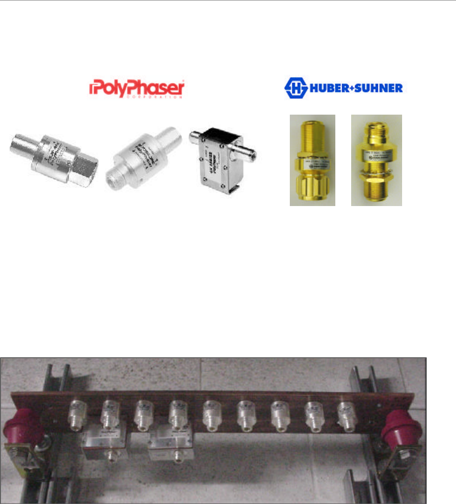
Figure 11: Surge Protectors
From left to right: PolyPhaser surge protectors are used with the Combo Chassis and Split
Chassis configurations (PSX-ME for the Cal and RF cables, at the antenna, PSX for the Cal and
RF cables at the ground Buss Bar, and DGXZ+06NFNF-A for the GPS antenna cable at the
ground Buss Bar. Huber+Suhner surge protectors are used with TTA configurations
(3406.17.0012 PSX for the Cal and GPS cables, and for the Ancillary Surge protection at the
RFS; 3406.17.0009 for the Ancillary Surge protection at the ground Buss Bar). It is
recommended the use of UL listed surge protectors.
Figure 12: Surge Protectors in Buss Bar
PSX-ME PSX DGXZ+06NFNF-A3406.17.0012 3406.17.0009
PSX-MEPSX-ME PSXPSX DGXZ+06NFNF-A3406.17.00123406.17.0012 3406.17.00093406.17.0009
Navini Networks, Inc. Ripwave Base Station I&C Guide
Chapter 2a
Part #40-00047-02 Rev F v1.0 (1.20) 47
October 9, 2003
Antenna Ground Buss Bar
You should install the Antenna Ground Buss Bar on the mounting structure per accepted telecom
standards and procedures (Figure 13). The location is decided on during the site survey and
should be close to the RFS. Two or more buss bars may be installed per system.
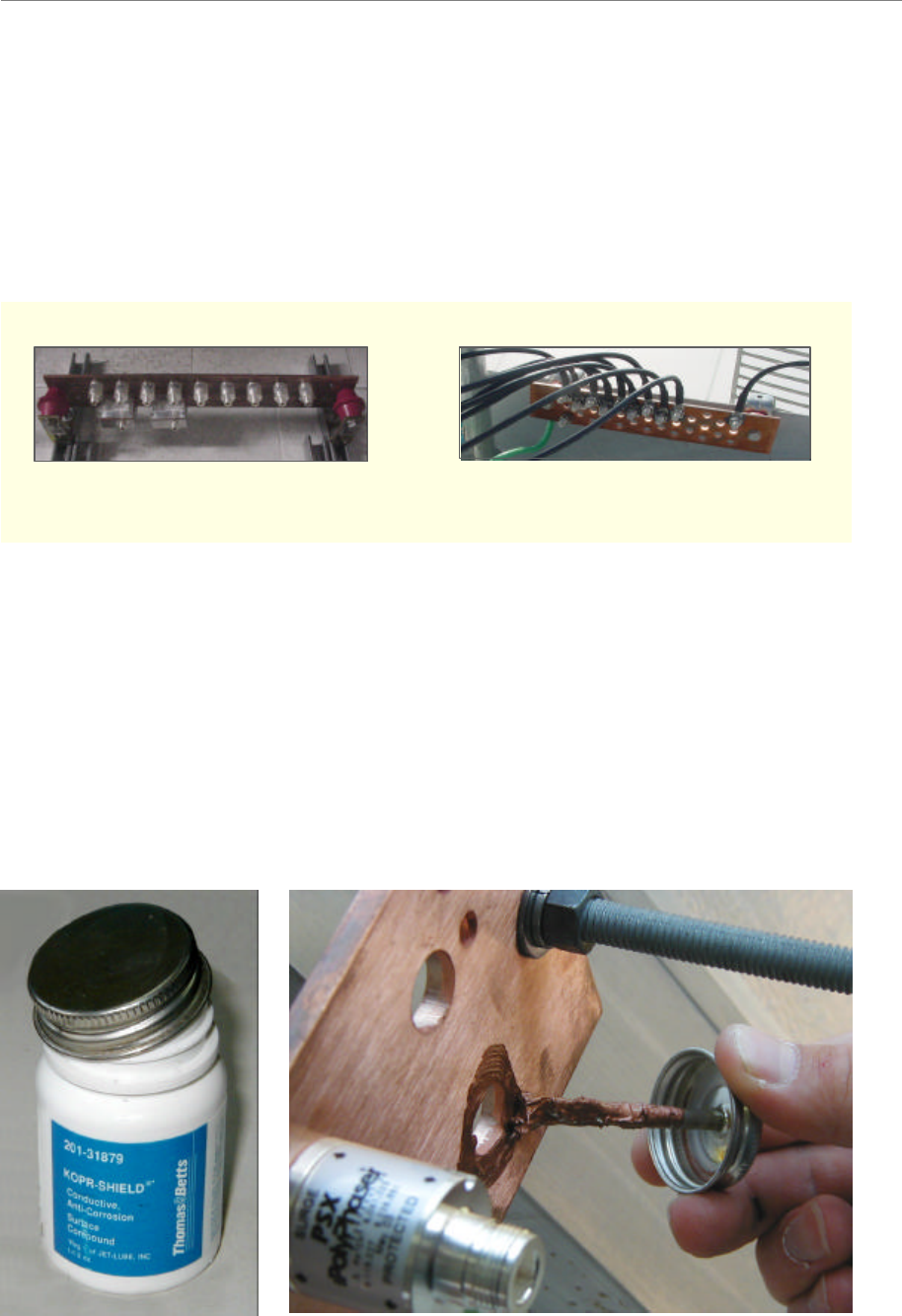
Figure 13: Buss Bars
System Ground Wiring
A minimum #6 stranded, green-coated copper wire and grounding hardware are used for ground
connections. Install the system ground as a single-point connection between the system ground
buss bars, the data/power surge protector, the BTS chassis, the BTS mounting rack, and the RFS
antenna. Connect the system ground to earth ground. Apply anti-oxidant joint compound to all
connections (Figure 14). Tighten all connections until secure.
Figure 14: Applying anti-oxidant joint compound
Antenna Buss BarBTS Buss Bar Antenna Buss BarBTS Buss Bar
Ripwave Base Station I&C Guide Navini Networks, Inc.
Chapter 2a
48 Part #40-00047-02 Rev E v1.0 (TTA)
October 23, 2003
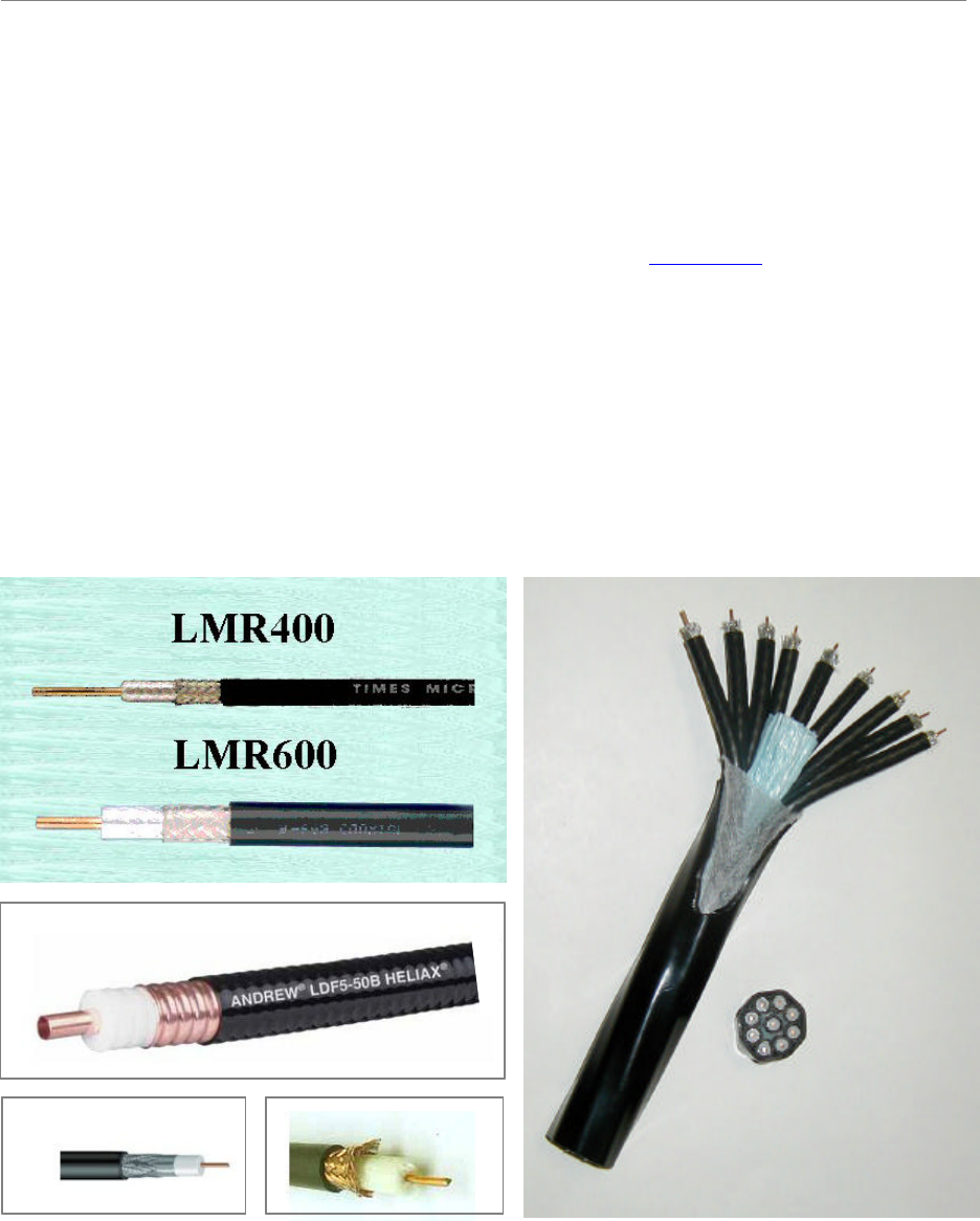
Install Cables
All cable connections in the Combo and Split-Chassis configurations are made using standard
RF coaxial cable. The Navini Networks minimum for cable connections from the GPS to the
BTS is LMR 400, 3/8-inch coaxial cable. Other types of cable that are comparable may be used.
These were determined under “Antenna Power & Cable Selection” (Appendix L) activities cited
earlier. The TTA configuration uses a composite cable containing nine RG-6 or RG-11
individual strands to replace the 8 RF cables, the Cal cable and the Power/Data cable (the signal
previously sent through the Power/Data cable is now sent through the center connector of the
individual RG-6 or RG-11 strands).
All Coaxial and Digital cables between the Digital and RF shelves are 60 inches in length.
Physical distance between Digital and RF shelves will always be less than the cable length.
Figure 15: Coaxial Cables.
HELIAX
RG-6 Bundle
RG6 RG11
HELIAX
RG-6 Bundle
RG6 RG11
Navini Networks, Inc. Ripwave Base Station I&C Guide
Chapter 2a
Part #40-00047-02 Rev F v1.0 (1.20) 49
October 9, 2003
Cut Cables for the Combo and Split Chassis Configurations
The cable run is determined during the site survey. Note that the length of the cables may need to
be slightly different, depending on the position of the buss bar relative to the BTS.
?? Cut nine (9) pieces of cable for the main feeder cables to connect the nine RFS
connectors to the surge protectors on the system ground buss bar. Leave enough extra
length for the service loop below the RFS and for connection to the surge protectors.
?? Cut eight (8) pieces of cable for the jumper cables to connect the surge protectors on the
system ground buss bar to the eight (8) RF input connectors on the back of the BTS.
Leave enough extra cable length for service.
?? Cut one (1) piece of cable for the jumper cable to connect the surge protector on the
system ground buss bar to the CAL connector on the back of the BTS. Leave enough
extra cable length for service.
?? Cut a piece of LMR 400 cable to connect each of the GPS antennas to the surge
protectors on the system ground buss bar. Leave enough extra cable length for service.
The maximum length of the LMR 400 cable for the GPS antenna is 100 feet.
?? Cut a piece of LMR 400 cable to connect the surge protectors on the system ground buss
bar to each GPS connector on the back of the BTS. Leave enough extra cable length for
service. If there is more than one BTS co-located in the installation, two GPS antennas
can serve all BTSs in the installation.
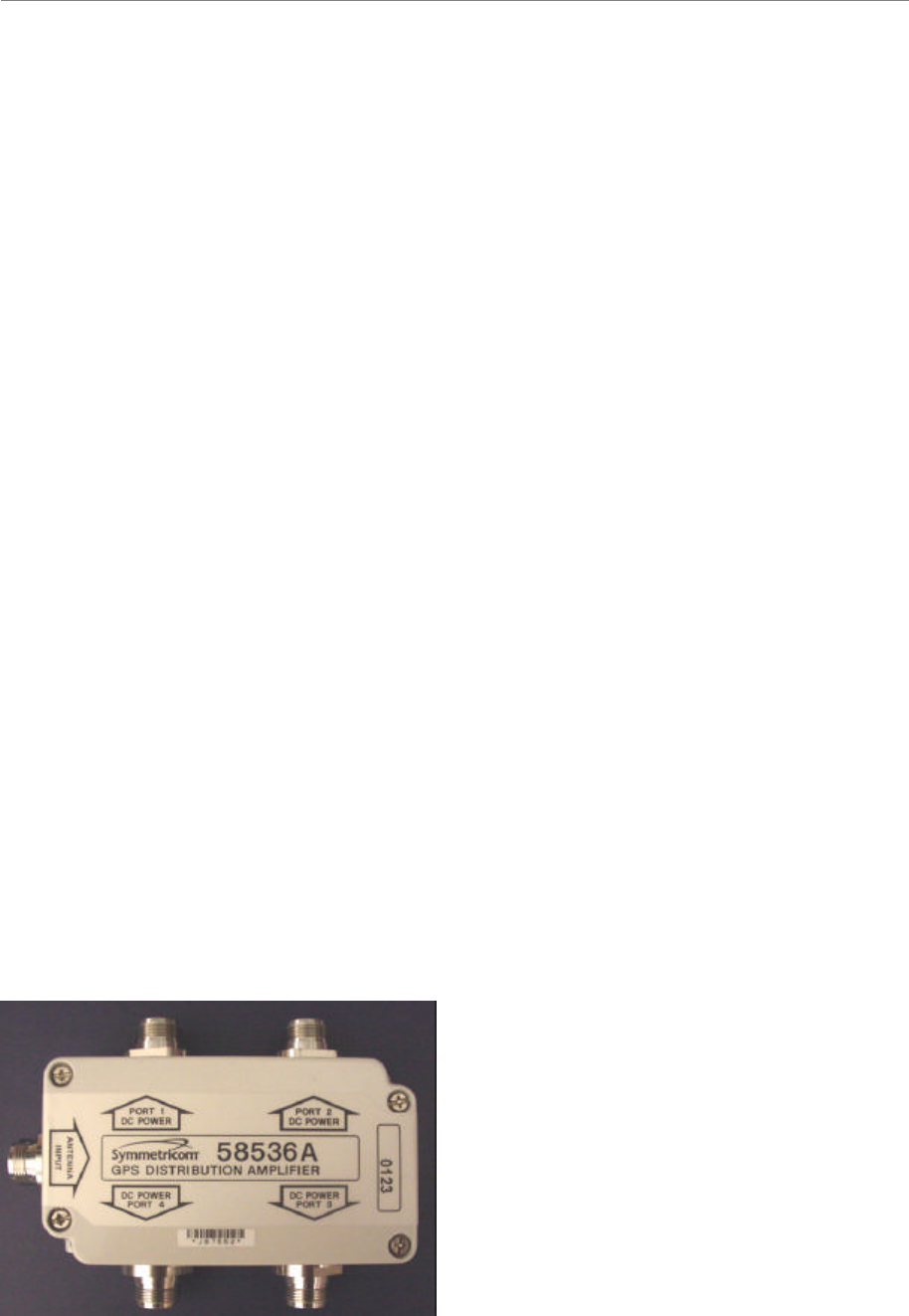
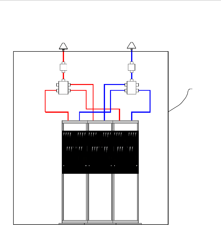
?? The cable from the GPS antenna (after it goes through the surge protector) is connected
to the antenna input of the GPS distribution amplifier (Figure 16). The output ports of the
GPS distribution amplifier are connected to the GPS inputs of the BTS. The GPS
distribution amplifier is powered by the GPS antenna input. The drawing in Figure 17
depicts the placement of the shared GPS resources among three BTSs.
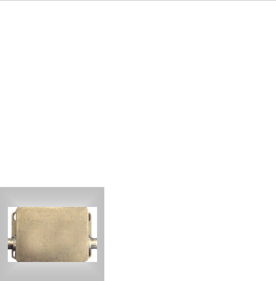
Figure 16: GPS Distribution Amplifier
Ripwave Base Station I&C Guide Navini Networks, Inc.
Chapter 2a
50 Part #40-00047-02 Rev E v1.0 (TTA)
October 23, 2003
Figure 17: Depiction of GPS Distribution Amplifier
GPS 1
Polyphaser
Distribution Amp
GPS 2
Polyphaser
Distribution Amp
BTS 1 BTS 2 BTS 3
SHELTER
Navini Networks, Inc. Ripwave Base Station I&C Guide
Chapter 2a
Part #40-00047-02 Rev F v1.0 (1.20) 51
October 9, 2003
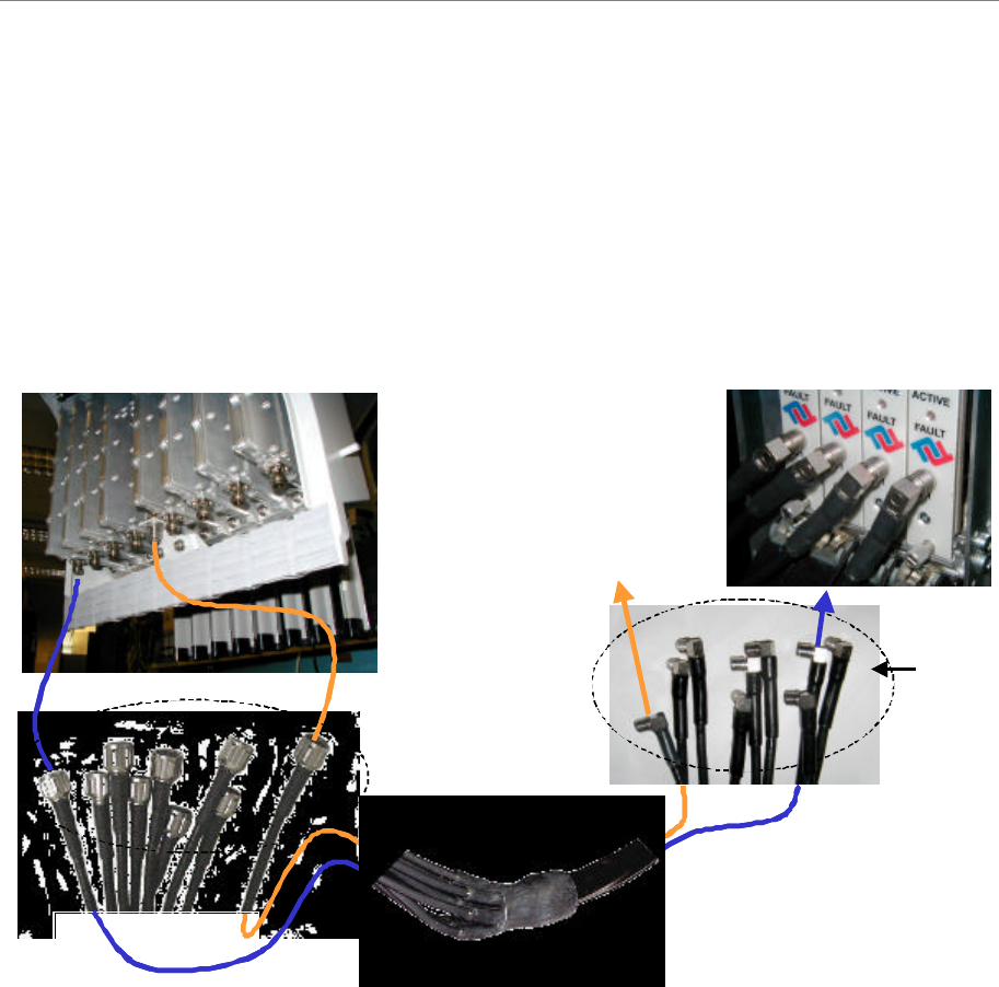
Cut Bundle Cable for the TTA Configuration
On the end that attaches to the antenna, the RG-6 or RG-11 bundle cable comes with a
weatherized “boot” and nine the N-type Male connectors in place. Cut the cable to the proper
length at the other end and attach the proper connectors.
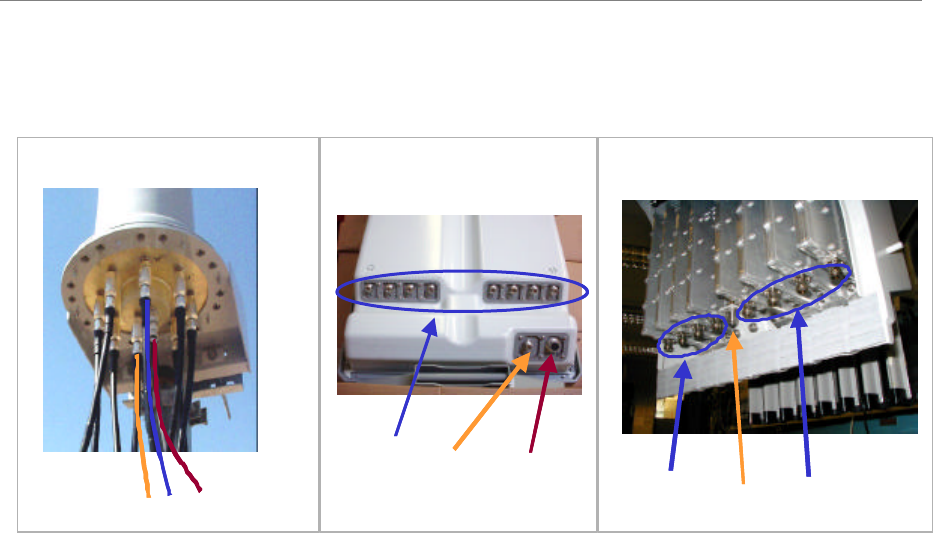
Figure 18 Bundle Cable, Weatherized “Boot” and End Connectors
Cal Port
(BTS back plane)
RFCs
(BTS front)
N-type
QMA
Cal Port
(BTS back plane)
RFCs
(BTS front)
N-type
QMA
Ripwave Base Station I&C Guide Navini Networks, Inc.
Chapter 2a
52 Part #40-00047-02 Rev E v1.0 (TTA)
October 23, 2003
Install Connectors on Cables
Install connectors on both ends of each cable. For LMR 600 cables, install EZ-600 N-type male
connectors. For LMR 400 cables, install EZ-400 N-type male connectors. Steps for installing
both types of connectors can be found in Appendix N. For reference, Appendix L also provides a
list of vendors who can make cables.
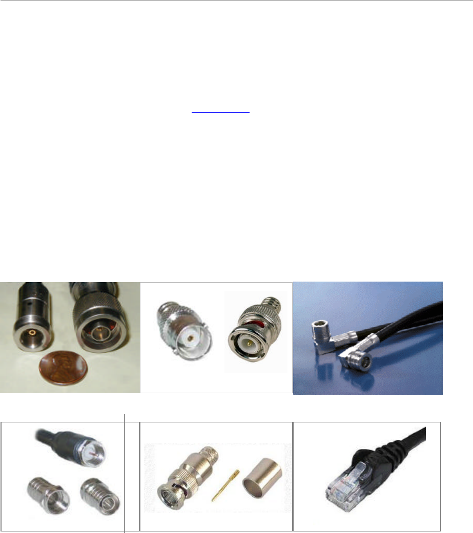
The Cal and RF cables in the Combo and Split Chassis configuration have N-type male
connectors at both ends. The Bundle Cable used with the TTA configuration has N-type male
connectors at the antenna end, but the connectors used at the other end depend on the degree of
lightning protection desired. Is only the built-in protection is used, the connectors at the BTS
end are QMA male, but if the Ancillary surge protectors are used, the connectors at the BTS end
of this cable are N-type male.
Figure 19: Connectors.
N-Type
FM
QMA
M
BNC
FM
RG6
Front Back
RG11 BNC RJ45/RJ48
N-Type
FM
QMA
M
BNC
FM
RG6
Front Back
RG11 BNC RJ45/RJ48
Navini Networks, Inc. Ripwave Base Station I&C Guide
Chapter 2a
Part #40-00047-02 Rev F v1.0 (1.20) 53
October 9, 2003
Sweep RF Cables
Sweep each individual cable, the RFS (8) and CAL main feeder and jumper cables, to check for
line loss. Follow the instructions for sweeping the cables provided in Appendix O entering the
results in the RFS System Test Form. Check continuity of the data/power cable. When finished,
cover the cable connectors for protection until they are connected to the RFS or GPS.
Connectorize & Run Cables
Connect all of the RF cables to the surge protectors in the system ground buss bar. An example
of a buss bar connection is shown in Figure 14. Ensure that the proper cable is connected to the
proper surge protector. Connect the power/data cable to its surge protector. Also connect all the
jumper cables to the surge protectors that will attach to the BTS. Do not connect these cables to
the BTS at this time. Torque all the cable connectors to the surge protectors on the system
ground buss bar to 20-24 inch-pounds.
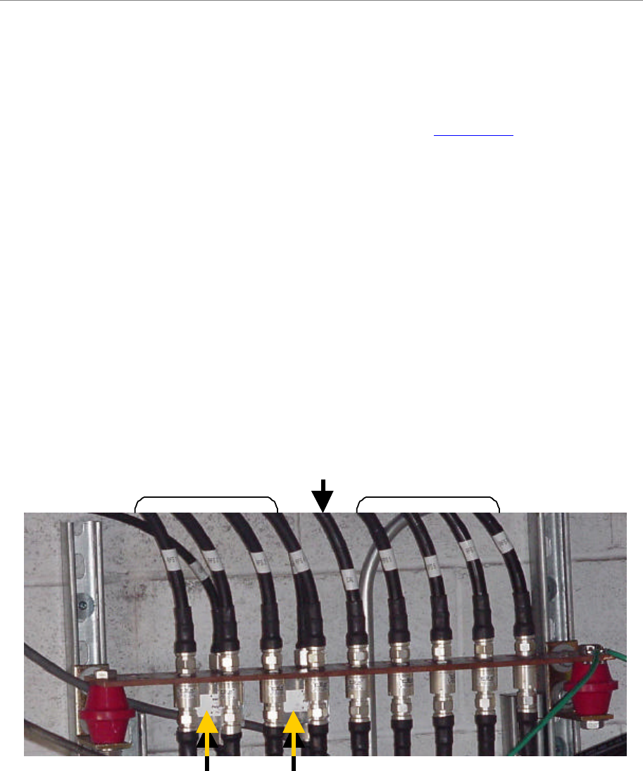
Figure 20: Buss Bar Connections
Route all of the cables – RFS (8), CAL, DATA/POWER and GPS (1 or 2) - between the system
ground buss bar and the RFS, and GPS mounting sites. If running the cables up a tower, use a
hoisting grip to lift the cables.
GPS 1 GPS2
RF 1-4RF 5-8
CAL
GPS 1 GPS2
RF 1-4RF 5-8
CAL
Ripwave Base Station I&C Guide Navini Networks, Inc.
Chapter 2a
54 Part #40-00047-02 Rev E v1.0 (TTA)
October 23, 2003
Figure 21: Cable Routing
CAL
Data/Power*
RF
CAL Data/Power*
RF
CAL
RF RF
Omni Panel 3.5 GHz TTA Panel
* In the TTA configurations, the Data/Power cable is no longer required
CAL
Data/Power*
RF
CAL Data/Power*
RF
CAL
RF RF
Omni Panel 3.5 GHz TTA Panel
* In the TTA configurations, the Data/Power cable is no longer required