Cisco Systems BTS-R3 Broadband Data BTS User Manual chpt 1 40 00047 01 F I C TTA
Cisco Systems, Inc Broadband Data BTS chpt 1 40 00047 01 F I C TTA
Contents
Manual 1

Ripwave™ Base Station
Installation & Commissioning Guide
Part Number 40-00047-01
Revision F (TTA), Version 1.0
October 23, 2003
Proprietary
All information disclosed by this document is the proprietary property of Navini Networks, Inc. and is protected by
copyright, trademark, and/or trade secret laws. All rights therein are expressly reserved.

Ripwave Base Station I&C Guide Navini Networks, Inc.
Chapter 1
2 Part #40-00047-01 Rev F v1.0 (TTA)
October 23, 2003
About This Document
Purpose
This document provides a Navini-certified Installation & Commissioning Technician or Field Engineer with
instructions to properly install the Base Transceiver Station (BTS), Radio Frequency Subsystem (RFS), and cabling;
and to test and commission the Base Station after installation.
Revision History
Date Revision/
Version Authors Editors Comments
2001 A/1.0 J. Price, C. Keltner, A.Chua,
P. Blain, J. Coulson, D.
Karina, K. Sharp, L. Hoffman
N/A Draft
4.02 B/v1.0 Same N/A Preliminary
8.30.02 C/1.0 Same N/A Prepare for release 1.16
9.3.02 C/1.0 Same S. Redfoot Review comments from class 8.30.02
9.27.02 C/1.0 Same Same Preliminary Commercial Release 1.18
10.18.02 C/1.0 Same Same Feedback on forms and specifications
2.7.03 D/1.0 Same Same Combined all Base Station I&C into
one manual; Preliminary 1.19
2.28.03 D/1.0 Same Same Standard Release 1.19
4.4.03 D/1.0 Same Same File Mngtchanges, no content change
7.30.03 E/1.0 Same + R. Hernandez
E. Curl, M. Johnson Same Standard Release 1.20
9.12.03 F/1.0 J. Coulson + L. Font L. Font Draft updates for TTA trials
9.27.03 F/1.0 D. Karina, E. Condon S. Redfoot
& L. Font
UL & TTA updates; TOC, Grounding
diagrams (Fig 1, 2, 3), Flow Diagram,
Technical Specs Table, inclinometer
10.04.03 F/1.0 H. Bhakta, Mitch Johnson L.Font Changes required for UL compliance.
2.4 TTA and 3.5 TTA tables added to
Appx O. Page and TOC renumbering.
10.09.03 F/1.0 L.Font Consolidated changes after Oct 9
review. Plurals of acronyms.
10.23.03 F/1.0 J.Coulson, P.Prudhomme,
L.Font L.Font Some drawing updates pending from
the Oct 9 review. Magnetic Declination
charts update.

Navini Networks, Inc. Ripwave Base Station I&C Guide
Chapter 1
Part #40-00047-01 Rev F v1.0 (TTA) 3
October 23, 2003
Contacts
Contact Navini Networks Technical Support during normal business hours: Monday through Friday 8:30 a.m. to
5:30 p.m. Central Time. You can also submit questions or comments by web or email at any time.
Corporate Headquarters: (972) 852-4200
Technical Support: 1-866-RIPWAVE
Local Number: (972) 852-4389
Web Address: www.navini.com / select Technical Support
E-mail: techsupport@navini.com
Navini Networks, Inc.
2240 Campbell Creek Blvd.
Suite 110
Richardson, Texas 75082
USA

Ripwave Base Station I&C Guide Navini Networks, Inc.
Chapter 1
4 Part #40-00047-01 Rev F v1.0 (TTA)
October 23, 2003
Permissions, Trademarks & Distribution
Copyright© September 2003, Navini Networks, Inc. All information contained herein and
disclosed by this document is the proprietary property of Navini Networks, Inc. and all rights
therein are expressly reserved. Acceptance of this material signifies agreement by the recipient
that the information contained in this document is confidential and that it will be used solely for
the purposes set forth herein. Acceptance of this material signifies agreement by the recipient
that it will not be used, reproduced in whole or in part, disclosed, distributed, or conveyed to
others in any manner or by any means – graphic, electronic, or mechanical, including
photocopying, recording, taping, or information storage and retrieval systems – without the
express written permission of Navini Networks, Inc.
Navini Networks, Internet at the Speed of Thought, zero-install, unwired by Navini, the Navini
Networks logo, and Ripwave are trademarks of Navini Networks, Inc. Other product and
company names mentioned herein may be trademarks and/or service marks of their respective
owners.
Nothing herein constitutes any representation, warranty, assurance, or guaranty of any
kind.
Because of continuing developments and improvements in design, manufacturing, and
deployment, material in this document is subject to change without notification and does not
represent any commitment or obligation on the part of Navini Networks, Inc.
Navini Networks, Inc. shall have no liability for any error or damages resulting from the use of
this document. Any unauthorized usage is strictly prohibited without the express written
permission of Navini Networks, Inc.
Copyright ? 2003 Navini Networks, Inc. All Rights Reserved.
Navini Networks, Inc.
2240 Campbell Creek Boulevard
Suite 110
Richardson, Texas 75082
USA

Navini Networks, Inc. Ripwave Base Station I&C Guide
Chapter 1
Part #40-00047-01 Rev F v1.0 (TTA) 5
October 23, 2003
TABLE OF CONTENTS
About This Document 2
Permissions, Trademarks & Distribution 4
Table of Contents 5
Safety 6
Regulatory Information 7
Battery Caution & Procedures 10
Glossary of Terms & Abbreviations 11
CHAPTER 1: OVERVIEW 20
RIPWAVE DESCRIPTION 21
PROCEDURAL DOCUMENTS & FORMS 23
HIGH-LEVEL I&C PROCESS FLOWCHART 23
BASE STATION COMPONENTS 34
TECHNICAL SPECIFICATIONS 38
BTS INPUT/OUTPUT SPECIFICATIONS 39
CHAPTER 2: INSTALLATION 41
PRE-INSTALLATION 41
INSTALL POWER & GROUNDING 45
INSTALL CABLES 48
INSTALL THE BTS 55
INSTALL GPS ANTENNAS 60
INSTALL THE RFS 61
VERIFY INSTALLED CIRCUIT CARDS 73
BASE STATION INSTALLATION CERTIFICATION 74
CHAPTER 3: COMMISSIONING 75
REVIEW CUSTOMER NETWORK PLANS 75
INSTALL EMS SERVER 75
VERIFY CABLE CONNECTIONS 76
CONFIGURE & POWER UP THE BTS 77
CALIBRATE THE BASE STATION 100
PERFORM THE CALIBRATION VERIFICATION PROCEDURE 104
SINGLE ANTENNA TEST 104
EXPORT BTS DATA 104
PERFORM LOCAL MODEM TESTS 104
INSTALL & TEST CUSTOMER EMS OPERATIONS 105
PERFORM CALIBRATION USING CUSTOMER’S EMS 106
VERIFY SYSTEM PERFORMANCE 106
VERIFY SYSTEM OPERATION WITH MULTIPLE MODEMS 107
BACK UP EMS DATABASE 107
CUSTOMER ACCEPTANCE 107

Ripwave Base Station I&C Guide Navini Networks, Inc.
Chapter 1
6 Part #40-00047-01 Rev F v1.0 (TTA)
October 23, 2003
APPENDICES
A: SAMPLE STATEMENT OF WORK (SOW) 109
B: SAMPLE RESPONSIBILITY ASSIGNMENT MATRIX (RAM) 113
C: SAMPLE WORK BREAKDOWN STRUCTURE (WBS) 121
D: SITE CANDIDATE EVALUATION FORM 123
E: INTERFERENCE SWEEP PROCEDURE 135
F: INTERFERENCE SWEEP TOOL 141
G: BTS SPECIFICATIONS 147
H: RFS DATA SHEETS 155
I: BTS OUTDOOR ENCLOSURES GUIDE 159
J: RECTIFIER/BATTERY BACKUP SPECIFICATIONS 161
K: SAMPLE BASE STATION DRAWING 163
L: ANTENNA POWER & CABLE SELECTION PROCEDURE & FORM 165
M: SAMPLE BILL OF MATERIALS 171
N: INSTALL CONNECTORS ON CABLES PROCEDURE 175
O: RFS SYSTEM TEST (CABLE SWEEP) 181
P: BTS CHASSIS ALARMS 203
Q: SAMPLE TRI-SECTORED BTS GROUNDING DRAWING 205
R: SAMPLE TRI-SECTORED BTS POWER DRAWING 207
S: SINGLE ANTENNA TEST PROCEDURE 209
T: BASE STATION INSTALLATION CERTIFICATION FORM 217
U: EXCEL CONFIGURATION FORM 221
V: BASE STATION CALIBRATION VERIFICATION PROCEDURE & FORM 243
W: LOCAL MODEM TEST PROCEDURES 251
X: DRIVE STUDY PROCEDURE & FORM 257
Y: LOCATION (FTP) TEST PROCEDURE & FORM 263
Z: SITE INSTALLATION CLOSE-OUT DOCUMENTATION 271
AA: CUSTOMER ACCEPTANCE FORM 275

Navini Networks, Inc. Ripwave Base Station I&C Guide
Chapter 1
Part #40-00047-01 Rev F v1.0 (TTA) 7
October 23, 2003
Safety
To optimize safety and expedite installation and service, read this document thoroughly. Follow
all warnings, cautions, and instructions marked on the equipment and included in this document.
To aid in the prevention of injury and damage to property, cautionary symbols have been placed
in this document to alert the reader to known potentially hazardous situations, or hazards to
equipment or procedures. The symbols are placed before the information to which they apply.
However, any situation that involves heavy equipment and electricity can become hazardous, and
caution and safety should be practiced at all times when installing, servicing, or operating the
equipment.
Caution Symbol - possible equipment or property damage
Warning Symbol - could cause personal injury or otherwise be hazardous to
your health
Navini Networks, Inc., expressly requires that when using Navini electronic equipment always
follow the basic safety precautions to reduce the risk of electrical shock, fire, and injury to
people and/or property.
1. Follow all warnings and instructions that come with the equipment.
2. Do not use the equipment while you are in a bathtub, shower, pool, or spa. Exposure of the
equipment to water could cause severe electrical shock or serious damage to the equipment.
3. Do not allow any type of liquid to come in contact with the equipment. Unplug the
equipment from the power source before cleaning. Use a damp cloth for cleaning. Do not use
any soaps or liquid cleaners.
4. Follow all airport and FAA regulations when using the equipment on or near aircraft.
5. Only operate the equipment from the type of power source(s) indicated in this manual (110
VAC or Navini supplied battery). Any other type of input power source may cause damage to
the equipment.
6. Power the equipment using only the battery or the AC adapter cable provided, and in
accordance with the instructions specified in the User Guide.
7. Do not use a frayed or damaged power cord. Do not place the power cord where it can be
stepped on or tripped over.
8. Do not touch wires where the insulation is frayed or worn unless the equipment has been
disconnected from its power source.
9. Do not overload wall outlets, power strips, or extension cords. This can cause serious
electrical shock or fire.
10. Do not place the equipment on an unstable surface. It can fall and cause injury or damage to
the equipment.

Ripwave Base Station I&C Guide Navini Networks, Inc.
Chapter 1
8 Part #40-00047-01 Rev F v1.0 (TTA)
October 23, 2003
11. Do not disassemble the equipment. Removing covers exposes dangerous voltages or other
risks and also voids the warranty. Incorrect reassembly can cause equipment damage or
electrical shock. Only an authorized repair technician should service this product.
12. Do not expose the equipment to extreme hot or cold temperatures.
13. Do not use the equipment under the following conditions:
?? When the equipment has been exposed to water or moisture.
?? When the equipment has been damaged.
?? When the power cord is damaged or frayed.
?? When the equipment does not operate properly or shows a distinct
change in performance.

Navini Networks, Inc. Ripwave Base Station I&C Guide
Chapter 1
Part #40-00047-01 Rev F v1.0 (TTA) 9
October 23, 2003
Regulatory Information
FCC Notice
WARNING! This device is a Radio Frequency transmitter. It is required to comply with
FCC RF exposure requirements for transmitting devices. A minimum separation distance
of 2 meter or more must be maintained between the antenna and all persons during device
operations to ensure compliance with the FCC’s rules for Radio Frequency Exposure. If
this minimum distance cannot be maintained, exposure to RF levels that exceed the
FCC’s limits may result.
INFORMATION TO USER
This device has been authorized as a radio frequency transmitter under the appropriate
rules of the Federal Communications Commission. Any changes or modifications not
expressly approved by Navini Networks could void the user’s authority to operate the
equipment.
UL & NEC/CEC Regulations
1. The Ripwave BTS must be installed in accordance with NEC/CEC Articles 800/810/830.
2. As a minimum, all DC power leads and bonding/grounding straps shall be 6 AWG
copper conductors.
3. GPS, RF, and power/data cables in excess of 140 feet in length must have protective
devices installed that are UL listed to UL 492, UL497A or UL497B, UL497C, and
UL1449.
4. If lightning protection is required, the device(s) must comply with UL497.
5. Power supplies should be UL listed to UL60950 or UL60950-1 and have earthed SELV
output.
6. Ethernet connections require a UL497B listed protection device to be installed between
the BTS and the first network device. T1 connections must be routed from the BTS
through a UL497 listed protection device at the demarcation point.
7. T1 interconnect cables between the BTS and demarcation point must be a minimum of
#26 AWG wire, in accordance with NEC/CEC standards.
8. All power and ground conductors must be mechanically supported to avoid strain of the
wires and connection points.
9. A UL listed disconnect device, such as a circuit breaker or fuse, must be installed
between the power supply and BTS chassis connections.
10. Power-interconnect wires between the power supply/recitifier and the BTS Digital
chassis must have heat shrink tubing applied over the barrel of the terminal lugs after
crimping the wire. A picture is provided in the “Installation” section of this manual.
11. If it is necessary to replace a fuse on a CHP, CC or PA board, a fuse of the same type and
with the same rating must be used to insure continued protection against risk of fire.

Ripwave Base Station I&C Guide Navini Networks, Inc.
Chapter 1
10 Part #40-00047-01 Rev F v1.0 (TTA)
October 23, 2003
Battery Caution & Procedures
WARNING! To reduce risk of injury or fire, follow these instructions when handling the
battery.
1. Risk of explosion is possible if the battery is replaced with one not supplied by Navini
Networks.
2. Do not dispose of the battery in a fire. It may explode. Check with the local codes for
battery disposal guidelines.
3. Do not open or mutilate the battery. The battery contains substances that are toxic,
corrosive, or harmful to humans. If battery substances come in contact with the skin,
seek medical help immediately.
4. Do not attempt to recharge the battery by any means except per the instructions in this
manual.
5. Remove the battery from the equipment if the equipment is not going to be used for a
long period of time. The battery could leak and cause damage to the equipment.
6. Exercise care when handling the battery to prevent shorting the battery with conducting
materials such as bracelets, rings, and keys.
7. Store the battery pack in a dry place, 0 to +40 degrees Celsius.
8. Dispose of used batteries according to environmental guidelines.

Navini Networks, Inc. Ripwave Base Station I&C Guide
Chapter 1
Part #40-00047-01 Rev F v1.0 (TTA) 11
October 23, 2003
Glossary of Terms & Abbreviations
Term Stands For.... Meaning
802.11 802.11 Standard An IEEE LAN standard for wireless Ethernet replacement
technology in the ISM band. Runs at up to 10 Mbps.
ACC Access Channel or
Access Code Channel AKA, Paging Channel. The signal path that tells a mobile to
prepare for an incoming call.
ACK Acknowledge Positive message sent by a protocol to acknowledge reception
of a transmitted packet
AP Access Point Wireless LAN transceiver that acts as a center point of an all-
wireless network or as a connection point between wireless and
wired networks.
AMI Alternate Mark Inversion Old method for encoding data on a 64 kbps channel, which
requires 8 kbps to maintain synchronization, leaving only 56
kbps available to transmit data
ARP Address Resolution Protocol The function of the ARP is to match higher-level network IP
addresses with the physical hardware address of a piece of
equipment.
ARQ Automatic Repeat reQuest A protocol for error control in data transmission that
automatically requests the transmitter to resend a packet when
the receiver detects an error in the packet.
ASYNCH Asynchronous
Not occurring at regular intervals, as in dat
a piped over a
network
AWG American Wire Gauge A measure of thickness of copper, aluminum or other wiring in
the U.S.
ATM Asynchronous Transfer Mode Transporting a broad range of user data at irregular intervals
over network facilities
B8ZS Biploar 8-Zero Substitution An encoding method used on T1 circuits that inserts two
successive ones of the same voltage - referred to as a bipolar
violation - into a signal whenever eight consecutive zeros are
transmitted.
BB Broadband RF system with constant data rate of 1.5 Mbps or higher.
BBU Battery Backup Unit Equipment used to keep a BTS operating in the event of a
power outage
BCC Broadcast Code (or Control)
Channel A channel of data transmitted by one entity and received by
many devices.
BoM Bill of Materials
List of the actual equipment to be manufactured and shipped to
the installation site.
BS Base Station
Network Access equipment and software that transmits and
receives, as well as processes, voice or data calls from mobile
units to network connections.
A Ripwave Base Station consists
of the Base Transceiver Station (BTS) and the Radio
Frequency Subsystem (RFS), or antenna, plus a Global
Positioning System (GPS) antenna for timing.
BTS Base Transceiver Station The Ripwave BTS is a two-shelf rack that holds the RF
modules and digital circuit cards that interpret radio signals
into computer language and sends messages to and from the
local or wide area network. It functions between the RFS and
the EMS to handle the signaling.
BW Bandwidth Frequency spectrum usable for data transfers. It describes the
maximum data rate that a signal can attain on the medium
without encountering significant loss of power. Usually
expressed in bits per second (digital) or Hertz (analog).
BYTE Byte 8 bits

Ripwave Base Station I&C Guide Navini Networks, Inc.
Chapter 1
12 Part #40-00047-01 Rev F v1.0 (TTA)
October 23, 2003
Term Stands For.... Meaning
CAM 1Configuration & Alarm Manager or
2Content Addressable Memory
1An EMS functionality that is handled through a Graphical
User Interface for purposes of configuring elements in the
system and handling other OAM requirements. 2Module of the
BTS software used to provide mappings of users to channels.
CBR Constant Bit Rate One of the two service categories available for the
Management PVC in the ATM/T1 BTS configuration (the
other one is UBR)
CC 1Communications Controller or
2Cross-check
1A type of circuit card that resides in the Digital shelf of the
Ripwave BTS. It handles all interfaces between BTS and
network. 2An EMS functionality that allows the system to
perform an automated sanity check of the datafill.
CD 1Compact Disk or 2Change Directory
1An optical disk capable of storing large amounts of data (700x
floppy disk). It can be inserted into most PCs and “read” to
load files onto a computer 2A software programming term in
“C” language that tells the computer to go to a different
location in the computer’s memory.
CDMA Code Division Multiple Access Digital cellular technology that uses a spread-spectrum
technique where individual conversations are encoded with a
random digital sequence. Increases capacity and speed of
communications messages between mobile units over other
types of wireless networks.
CD-ROM Compact Disk - Read Only Memory See “CD.” If a CD is not Read Only, computers can write data
to it with that capability.
CDVT Cell Delay Variation Tolerance Delay variation parameter required by UBR and CBR.
CHP Channel Processor Card A card in the digital shelf of the BTS that performs the first
stage of signal processing for up to 4 antennae. One Navini 2.4
GHz BTS has 8 antennae. The card performs digital-to-analog
conversion (DAC) and analog-to-digital conversion (ADC) for
up to 10 carriers.
CLEC Competitive Local Exchange Carrier A telephone company that competes with an incumbent Local
Exchange Carrier (LEC).
CLI Command Line Interface A text -based programming language through which a user
communicates with an operating system or an application.
CORBA Common Object Request Broker
Agent A standard for Network Management Systems that allows
integration with NMS regardless of programming language or
Operating System.
CPE Customer Premise Equipment Communications equipment that resides at the customer’s
location.
D4 D4 A framing standard for traditional time-division multiplexing,
which standard describes user channels multiplexed onto a
trunk that has been segmented (framed) into 24 bytes of 8 bits
each. (See also ESF.)
dB Decibel Unit of measurement for sound. A logarithmic expression of
the ratio between two signal power, voltage, or current levels.
A decibel is one-tenth of a Bel, a seldom-used unit named for
Alexander Graham Bell, inventor of the telephone.
dBd Decibel/Dipole A ratio, measured in decibels, of the effective gain of an
antenna compared to a dipole antenna (2 horizontal rods in line
with each other). The greater the dBd value the higher the gain
and therefore the more acute the angle of coverage.

Navini Networks, Inc. Ripwave Base Station I&C Guide
Chapter 1
Part #40-00047-01 Rev F v1.0 (TTA) 13
October 23, 2003
Term Stands For.... Meaning
dBi Decibel/Isotropic A ratio, measured in decibels, of the effective gain of an
antenna compared to an isotropic antenna (measured along
axes in all directions). The greater the dBi value the higher the
gain and therefore the more acute the angle of coverage.
DHCP Dynamic Host Configuration
Protocol
A protocol for dynamically assigning IP addresses to devices
on a network.
DiffServ Differentiated Service Different Quality of Service (QoS) descriptions for different
types of traffic, i.e., voice, video, email. The DiffServ table is
where each level of QoS is defined. Equivalent to Class of
Service (COS) in POTS.
DIR Directory A special kind of file used to organize other files into a
hierarchical structure.
DL DownLink In this case, data messages transmitted from the BTS to the
CPE.
DNS Domain Name Server TCP/IP networking term that is a protocol for matching objects
to network (IP) addresses.
DS-1 Digital Signal - 1 Also “T1” or “E1”. Digital transmission equipment that can
handle up to 1.544 Mbps.
DSL Digital Subscriber Line A type of service whereby users gain access to the Internet
through high-speed data networks.
DSP Digital Signal Processing/Processor Compressing or manipulating analog signals to digital signals
and vice-versa.
EID Equipment Identifier Field in EMS for assigning IP address or name to individual
pieces of equipment for purposes of configuring the system.
EMS Element Management System An application that allows the user to define and manipulate
managed objects as a system within an overall network.
enet Ethernet The most widely-installed local area network (LAN)
technology. Ethernet is specified in the IEEE 802.3 standard
and typically uses coaxial cable or special grade of twisted pair
wires.
ERP Effective Radiated Power The actual power in Watts radiated from a transmitter’s
antenna.
ESF Extended Superframe In T-carrier, a synchronization frame that delineates 24 DS1
frames Note: ESF requires less frequent synchronization than
the T-carrier D4 superframe format. (See also D4.)
FCC Federal Communications
Commission
United States government regulatory agency that supervises,
licenses and otherwise controls electronic and electromagnetic
transmission standards.
FE Far End A relative term that refers to the receiving element in a
network, as opposed to the near-end element that is
transmitting data.
FEC 1Forward Error Correction or
2Fast Ethernet Controller
1A system of error control for data transmission wherein the
receiving device has the capability to detect and correct any
character or code block that contains fewer than a
predetermined number of symbols in error. 2A process created
and attached during BTS booting for the 10/100 Ethernet ports
on the BTS.
FTP File Transfer Protocol A TCP/IP method consisting of a client and server and used to
transfer files between two or more sites or elements in a
network.

Ripwave Base Station I&C Guide Navini Networks, Inc.
Chapter 1
14 Part #40-00047-01 Rev F v1.0 (TTA)
October 23, 2003
Term Stands For.... Meaning
Gain Gain Ratio of the output amplitude of a signal to the input amplitude
of a signal, expressed in decibels (dB).
Gb Gigabit One billion (1,000,000,000) bits.
GB Gigabyte One billion (1,000,000,000) bytes.
GHz Gigahertz One billion (1,000,000,000) hertz - cycles per second. Ultra
high frequency (UHF) signals, including microwave signals.
GPS Global Positioning System A constellation of 24 well-spaced satellites that orbit the earth
and enable users with GPS antennas to pinpoint their exact
geographical position.
GUI Graphical User Interface A graphic rather than purely text based user interface to a
computer or computing system.
HW Hardware Physical, tangible equipment
Hz Hertz 1 cycle per second.
I&C Installation & Commissioning Term used to describe the procedures of physically installing
technical equipment then powering up the equipment to make
sure it will operate (to put it “into commission”).
IEC Inter-exchange Carrier Also IXC. Public switching network service provider (carrier)
that connects across and between local exchange carriers
(LEC).
IF Interface Card Card on the digital shelf of the Ripwave BTS that takes the
analog signal from the Channel Processor card (CHP) and
converts it to a baseband signal before sending it on to the RF
modules for transmission (forward link), and vice-versa
(reverse link).
IMA Inverse Multiplexing over ATM A method of building dynamic routes of 2 or more T1s to
increase bandwidth so that PVCs can share the IMA resources,
as needed, for data transmissions.
inet Internet A worldwide system of computer networks in which users at
any one computer can, if they have permission, get information
from any other computer (and sometimes talk directly to users
at other computers.)
IP Internet Protocol A TCP/IP protocol used to route data from its source to its
destination.
ISM Industrial, Scientific and Medical Unlicensed band around 2.4 MHz
ISP Internet Service Provider A company that provides access to the Internet.
Kb Kilobit 1,024 bits
KB Kilobyte 1,024 bytes
KHz Kilohertz 1,000 hertz.
L1 Layer 1 Physical Layer. Part of the OSI rules and standards for network
management. L1 describes the physical layer, or electrical and
mechanical port-to-port connections, in the network.
L2 Layer 2 Data Link Layer. Part of the OSI rules and standards for
network management. L2 describes the data link layer where
data is set up and torn down in a specific format (frames),
through the overall network. Also responsible for detecting and
correcting errors by requesting retransmission.
L3 Layer 3
Network Layer. Part of the OSI rules and standards for
network management. L3 describes the network addressing
that gets data to its destination within the network, i.e., IP
addressing.
LAN Local Area Network A data network of interconnected computers, servers, printers,
and other peripherals that communicate at high speeds over
short distances, usually within the same building. Also allows
for sharing of resources.

Navini Networks, Inc. Ripwave Base Station I&C Guide
Chapter 1
Part #40-00047-01 Rev F v1.0 (TTA) 15
October 23, 2003
Term Stands For.... Meaning
LCP Link Control Protocol Basis of the Point-to-Point Protocol (PPP) scheme for negotiating
and establishing connections.
LDF see p.45
LED Light-emitting Diode An electronic device that lights up when electricity passes
through it. Often used to indicate equipment or system state.
LLC Logical Link Controller A protocol that governs the transition of frames between data
stations regardless of how the medium is shared. It’s the upper
sub-layer that further defines the Media Access Control (MAC)
protocol. It provides the basis for an unacknowledged
connectionless service on a LAN - i.e., error correction,
multiplexing, broadcasting.
LMR see p.45
LOS Line-of-sight Describes laser, microwave, RF, and infrared transmission
systems that require no obstruction in a direct path between the
transmitter and the receiver.
MAC Media Access Control Protocol that governs access to a network in order to transmit
data between nodes. In a wireless LAN, the MAC is the radio
controller protocol (L2).
Mb Megabit One million (1,000,000) bits.
MB Megabyte One million bytes. Literally - 1,048,576 bytes.
Mbps Megabits Per Second Transmission speed at rate of one million bytes per second.
MCBS Multi-Carrier Beam Forming
Synchronized Multiple Access technology used by Navini Ripwave systems
MDM Modem Card A card in the Navini BTS that converts digital signals into analog
so the signals can be transmitted over telephone lines, and vice-
versa. Modem stands for modulator/demodulator.
MHz Megahertz One million (1,000,000) hertz - cycles per second. Normally used
to refer to how fast a microprocessor can execute instructions.
MIB Management Information Base A collection of managed objects used in SNMP-based networks.
MIBs carry information in a standard format so external tools can
analyze network management and performance.
MMDS Multipoint Multi-channel
Distribution Service Fixed wireless, high-speed local service that operates at 2.1 - 2.7
GHz. Speed 10 Mbps. Originally conceived for cable TV service.
MME see p.92
NE 1Near-end or 2Network Element 1The transmitting end, versus the receiving end, of a signal
transmission. 2 A router, switch, or hub in an ISDN network.
NEC
National Electrical Code
Official rules and regulations that apply to the installation of
electrical equipment in the U.S.
NF
Noise Floor
NIC
Network Interface Card
A computer circuit board or card that is installed in a computer
so that it can be connected to a network. Network interface cards
provide a dedicated, full-time connection to a network.
NLOS
Non Line
-of-site Describes laser, microwave, RF, and infrared transmission
systems that can penetrate obstructions in the path between the
transmitter and the receiver.
NMS
Network Management System
A product that helps manage a network generally hosted on a
well
-
equipped computer such as an engineering workstation. The
system tracks network statistics and resources.
NOC
Network Operations Center
A centralized point, much like a traffic control tower, where
technicians or engineers can monitor network activity, alarms,
and statistics, as well as make network configuration and other
changes dynamically. For Internet, the NOC is often a hub for
ISP services.

Ripwave Base Station I&C Guide Navini Networks, Inc.
Chapter 1
16 Part #40-00047-01 Rev F v1.0 (TTA)
October 23, 2003
Term Stands For.... Meaning
OAM Operation, Administration,
Maintenance
A set of network management functions. Also describes the
human-machine interface tasks - i.e., to operate the system, to
administer the system, and to maintain the system.
OS Operating System A software program that manages the basic operation of a
computer. Most Operating Systems are either based on
OSI Open Systems Interconnection An ISO model for worldwide communications that defines 7
layers of network protocol: L1 Physical Layer; L2 Data Link
Layer; L3 Network Layer; L4 Transport Layer; L5 Session
Layer; L6 Presentation Layer; L7 Application Layer.
OTA Over-the-Air A standard for the transmission and reception of application-
related information in a wireless communications system.
PA Power Amplifier
PC Personal Computer Any IBM-compatible computer, so named because IBMs first
commercial end user computer was called a PC.
PCB Printed Circuit Board A hardware module that holds electronic circuitry and usually
fits into a larger frame where the various PCBs are
interconnected electronically.
PDU Packet Data Unit or Protocol Data
Unit A data packet. Refers to that which is exchanged between peer-
layer entities. Contains header, data, and trailer information.
Ping Ping Generalized term from sonar science, where a short sound burst
is sent out and an echo or “ping” is received. Used to determine
if signals or packets have been dropped, duplicated, or reordered.
PPPoE Point-to-point Protocol Over
Ethernet A protocol that allows dial-up Internet connections. Includes the
Link Control Protocol as well as Network Control Protocols.
PRC Peak Cell Rate
Propagation Propagation To spread out and affect a greater area; travel through space, as
in radio waves.
PSK Phase Shift Keying Digital transmission term that means an angle modulation where
the phase of the carrier varies in relation to a reference or former
phase. An encoded shift. Each change of phase carries one bit of
information, where the bit rate equals the modulation rate.
PSN Packet Switched Network A network in which data is transferred in units called packets.
Packets can be routed individually and reassembled to form a
complete message at the definition.
PSTN Public Switched Telephone
Network
Typically used in the same context as POTS. Analogous to a
network of major highways originally built by a single
organization but added to and expanded by multiple
organizations. AKA, backbone networks.
PVC Private Virtual Circuit A software-defined logical connection between end points in a
network.
QAM Quadrature Amplitude Modulation
A bandwidth conservation process routinely used in modems.
Creates higher throughput but decreased coverage area.
QoS Quality of Service A guaranteed throughput for critical network applications, such
as Voice over IP. Term primarily used in an ATM environment.
Five classes of service: Class 1 Video; Class 2 Audio; Class 3
Data Connection.
RAM 1Random Access Memory or
2Responsibility Assign Matrix
1Computer memory that can be accessed randomly. 2A document
created during the BTS installation and Commissioning, defining
who is responsible for performi
ng each task.
RBW Resolution Band Width A parameter set on the spectrum analyzer during insertion loss
measurements

Navini Networks, Inc. Ripwave Base Station I&C Guide
Chapter 1
Part #40-00047-01 Rev F v1.0 (TTA) 17
October 23, 2003
Term Stands For.... Meaning
RF Radio Frequency A portion of the electromagnetic spectrum in the frequency
range between audio and infrared: 100 KHz to 20 GHz. RF
measurements are expressed in Hz (unit for measuring
frequency); MHz = 1 Million Hz; GHz = 1 Billing Hz.
RFS Radio Frequency Subsystem A term for the antenna portion of the base station.
RH Relative Humidity The amount of water vapor in the air, given as the percent of
saturation humidity, generally calculated in relation to saturated
vapor density.
RMS Root mean Square The most common mathematical method of defining the effective
voltage or current of an AC wave
RS Reed-Solomon Reed-Solomon codes are block-based error correcting codes with
a wide range of applications in digital communications.
RSSI Receiver Signal Strength Indicator
A term that describes the measure of the signal strength in
kilohertz or gigahertz between the transmission and the receiving
end.
Rx Receive An abbreviated way of expressing the term, receive, as in to
receive a transmission.
S-CDMA Synchronous Code Division
Multiple Access Wireless technology based on data being transferred at a fixed
rate using Code Division Multiple Access algorithms.
SELV Safety Extra Low Voltage A secondary circuit which is designed and protected in such a
way that, under normal operative conditions or under a single
fault condition, its voltage does not exceed a safe value.
SLIP Serial Line Internet Protocol A TCP/IP protocol used for communication between two
machines that are previously configured for communication with
each other.
SMDS Switched Multi-megabit Data
Service
Connectionless service for MAN/WAN based on 53-
byte packets
that target the interconnection of different LANs into a public
switched network at speeds higher than T1.
SMS 1Short Message Service or
2Systems Management Server
1A protocol that allows mobile users to send text -
based messages
from one devi
ce to another. The text appears on a device’s screen
and may be a maximum 160 characters in length. 2A Windows
NT process that allows a network administrator to inventory all
hardware and software on the network, then perform software
distribution over the LAN.
SNMP Simple Network Management
Protocol Standard management request-reply protocol for managing
TCP/IP networks. A device is said to be SNMP compatible if it
can be monitored or controlled using SNMP messages.
SNR Signal-to-noise Ratio Related to RSSI, a measurement of the intended signal being
transmitted against the other entities that can interfere with the
signal.
SO/HO Small Office/Home Office Small, remote office with a MAN or WAN connection back to a
larger corporate network and/or the Internet.
SoW Statement of Work A document outlining the general activities that must be
conducted in order to complete the installation and
commissioning tasks for a Ripwave Base Station
SSI Signal Strength Indicator See “RSSI”.
SW Software Computer instructions or data.
SYN Synthesizer Card A circuit card in the Navini BTS digital shelf that provides a
local oscillator and system clock with a single calibration
transceiver. The card is used to calibrate the Base Station so that
no external spectrum analyzer or signal generator is required.
SYNCH Synchronous Digital packets or signals that are sent at the same, precisely
clocked fixed rate of speed.

Ripwave Base Station I&C Guide Navini Networks, Inc.
Chapter 1
18 Part #40-00047-01 Rev F v1.0 (TTA)
October 23, 2003
Term Stands For.... Meaning
TCC 1Traffic Channel or 2Transmission
Control Code
1A portion of a radio channel used to enable transmission of one
direction of a digitized voice conversation (as opposed to the
Voice Channel). 2A way of segregating traffic in order to define
controlled communities of interest among subscribers.
TCP Transport Control Protocol A standardized transport protocol between IP-based network
nodes that allows two hosts to establish a connection and
exchange streams of data. TCP operates on top of Internet
Protocols and handles the multiplexing of sessions, error
recovery, reliability and flow; it guarantees packets are delivered
in the same order in which they were sent.
TCP/IP Transport Control
Protocol/Internet Protocol A set of protocols that allows cooperating computers to share
resources across the network. TCP provides the reliability in the
transmission, while IP provides connectionless packet service.
TDD Time Division Duplex A digital transmission method that combines signals from
multiple sources and allows a single channel to alternately carry
data in each direction of a link.
TFFS True Flash File System Memory in a computing device that does not lose its information
when powered off. Available as a SIMM or PCMCIA card, it
usually stores router Operating System (OS) software. Can be
easily updated.
TTL Time-to-live A field in the Internet Protocol that specifies how many more
hops a packet can travel before being discarded or returned.
Tx Transmit To send by wire or other medium electronically or through air
via electromagnetic waves to a receiving communications device.
UBR Unspecified Bit Rate One of the two service categories available for the Management
PVC in the ATM/T1 BTS configuration (the other one is CBR)
UDP User Datagram Protocol A communications protocol that offers a limited amount of
service when messages are exchanged between computers in a
network that uses the Internet Protocol (IP). UDP is an
alternative to the Transmission Control Protocol (TCP.)
UL UpLink Describes the direction of signal flow being sent from a
subscriber to a network system, as in from a mobile device (CPE)
to a base station.
USB Universal Serial Bus An external bus standard for plug-and-play interfaces between a
computer and add-on devices, such as a mouse, modem,
keyboard, etc. One USB port can connect up to 127 devices.
VBW Video Band Width See p.100
VCC Virtual Channel Circuit AKA, Virtual Channel Connection or Virtual Circuit Connection.
A logical circuit made up of Virtual Channel Links, which carry
data between two end points in an ATM network.
VCI Virtual Channel Identifier A 16-bit value in the ATM cell header that provides a unique
identifier for the Virtual Channel that carries that particular cell.
VCL Virtual Channel Link A connection between two ATM devices.
VDC Volts Direct Current
Vector Vector A quantity representative of both magnitude and direction
(energy + orientation in space)
VPC Virtual Private Channel AKA, Virtual Path Connection. A grouping of Virtual Channel
Connectors, which share one or more contiguous VPLs.
VP Virtual Path A set of Virtual Channels grouped together between cross-
points
(i.e., switches).

Navini Networks, Inc. Ripwave Base Station I&C Guide
Chapter 1
Part #40-00047-01 Rev F v1.0 (TTA) 19
October 23, 2003
Term Stands For.... Meaning
VPI Virtual Path Identifier An 8-bit value in the cell header that identifies the VP as well as
the VC to which the cell belongs. The VPI + VCI identify the
next destination of a cell as it passes through a series of ATM
switches.
VPL Virtual Path Link A group of unidirectional VCLs with the same end points in a
Virtual Path. Grouping VCLs into VPLs reduces the number of
connections to be managed. One or more VPLs makes up a VPC.
WAN 1Wide Area Network or
2Wireless Access Network
1A communications network that spans geographically separate
areas and which provide long-haul services. Examples of inter-
networked connections are frame relay, SMDS, and X.25
protocols. 2 Ge neral term for any product primarily used to gain
access to the Internet, as opposed to being part of the actual
Internet devices or software.
WCS Wireless Communication Service Licensed band around 2.3 GHz
WEC WAN Ethernet Controller Process created during BTS booting and attached to the stack to
perform RFC1483 Ethernet bridging onto the ATM interface.
Ripwave Base Station I&C Guide Navini Networks, Inc.
Chapter 1
20 Part #40-00047-01 Rev F v1.0 (TTA)
October 23, 2003
Chapter 1: Overview
Ripwave Description
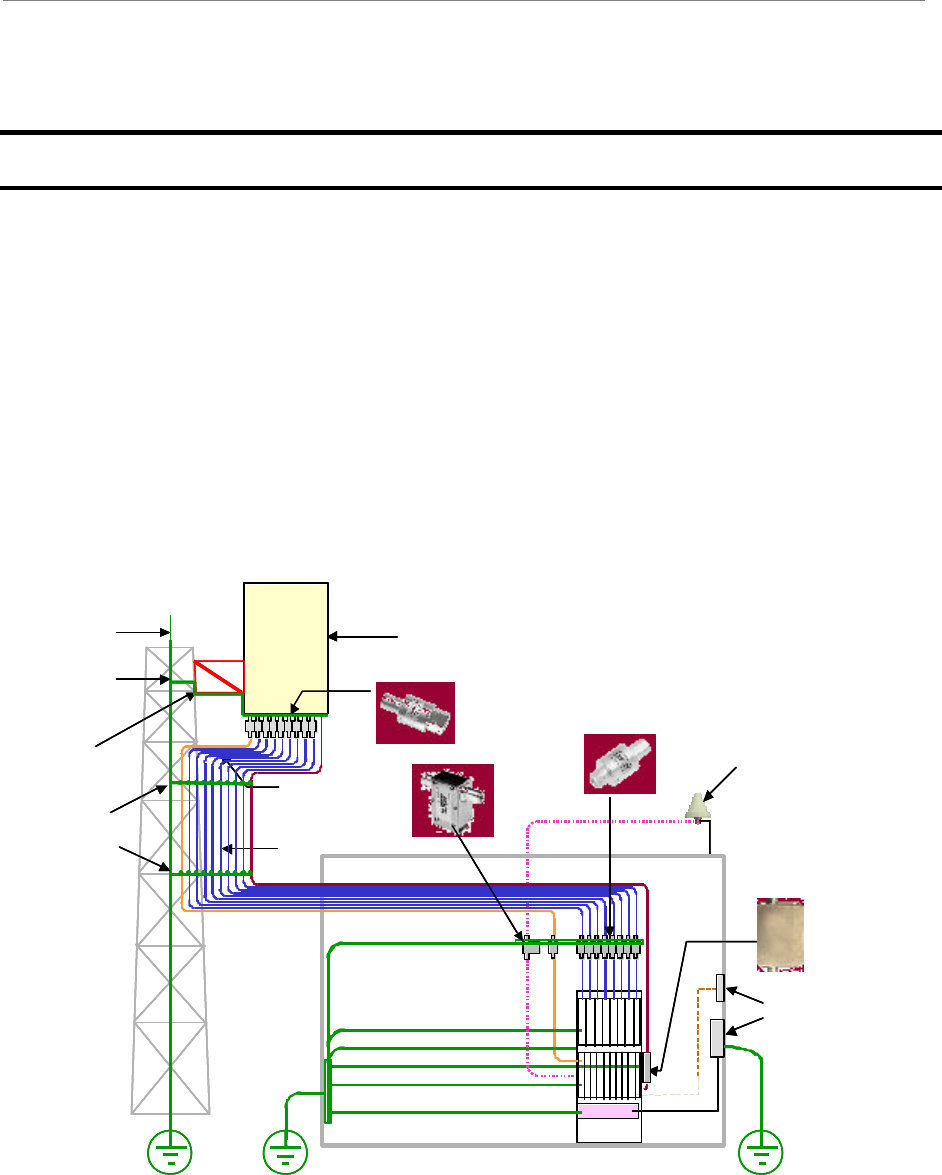
A Ripwave system has three main components: the Customer Premise Equipment (CPE); the
Base Station; and the Element Management System (EMS). The Base Station performs the CPE
registration and call processing, and provides the interface between the backhaul network and the
EMS. It is made up of the Base Transceiver Station (BTS) and the Radio Frequency Subsystem
(RFS) (Figure 1). This manual provides the guidelines and instructions for installing and
commissioning (I&C) the Base Station.
Figure 1: Base Station Installation (Combo and Split-Chassis Configurations)
Grounding
kits for
Coax Cable
Antenna
Bracket
Omni or Panel Antenna
Lightening
Ground
GPS Antenna
RF Shelf
Digital Shelf
Rectifiers (24 VDC, 60 A)
Cal cable
P&D cable Polyphasor
Power & Data cable
RF cables
Frame
Ethernet
110 VAC
Demarc.
PSX
PSX-ME
DGXZ+06NFNF-A
Power & Data
Cable Surge
Protector
GPS
Surge
Protector
Surge
Protectors Surge
Protectors
Grounding
kits for
Coax Cable
Antenna
Bracket
Omni or Panel Antenna
Lightening
Ground
GPS Antenna
RF Shelf
Digital Shelf
Rectifiers (24 VDC, 60 A)
Cal cable
P&D cable Polyphasor
Power & Data cable
RF cables
Frame
Ethernet
110 VAC
Demarc.
PSXPSX
PSX-MEPSX-ME
DGXZ+06NFNF-ADGXZ+06NFNF-A
Power & Data
Cable Surge
Protector
GPS
Surge
Protector
Surge
Protectors Surge
Protectors
Navini Networks, Inc. Ripwave Base Station I&C Guide
Chapter 1
Part #40-00047-01 Rev F v1.0 (TTA) 21
October 23, 2003
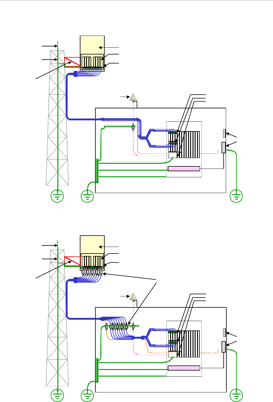
Figure 2: Base Station Installation (TTA Configuration with Built-In Surge Protection)
Figure 3: Base Station Installation (TTA Configuration with Ancillary Surge Protection)
Power Amplifiers
Built-in Surge Protectors
Omni or Panel Antenna
Lightning
Ground
Built-in
Surge Protectors
GPS Antenna
Digital Shelf
Rectifiers (24 VDC, 60 A)
Frame
RF
Cal
GPS
Antenna
Bracket
Ethernet
110 VAC
Demarc.
Power Amplifiers
Built-in Surge Protectors
Omni or Panel Antenna
Lightning
Ground
Built-in
Surge Protectors
GPS Antenna
Digital Shelf
Rectifiers (24 VDC, 60 A)
Frame
RF
Cal
GPS
Antenna
Bracket
Ethernet
110 VAC
Demarc.
Omni or Panel Antenna
Power Amplifiers
Built-in Surge Protectors
Lightning
Ground
RF
Cal
Digital Shelf
Rectifiers (24 VDC, 60 A)
Frame
GPS
Antenna
Bracket
GPS Antenna Built-in
Surge Protectors
Ethernet
110 VAC
Demarc.
Ancillary Surge Protectors
Omni or Panel Antenna
Power Amplifiers
Built-in Surge Protectors
Lightning
Ground
RF
Cal
Digital Shelf
Rectifiers (24 VDC, 60 A)
Frame
GPS
Antenna
Bracket
GPS Antenna Built-in
Surge Protectors
Ethernet
110 VAC
Demarc.
Ancillary Surge Protectors

Ripwave Base Station I&C Guide Navini Networks, Inc.
Chapter 1
22 Part #40-00047-01 Rev F v1.0 (TTA)
October 23, 2003
Procedural Documents & Forms
You will refer to other Ripwave documents, procedures, and forms in the process of installing
and commissioning the Base Station. The product documentation is provided on the Ripwave
Standard Documentation CD (Table 1). As well, the EMS manuals can be viewed on-line
through the EMS Server and Client applications.
Table 1: Ripwave Standard Documentation CD
Order Number 95-00116-00 Component or Part
Number Format
EMS Overview Manual 40-00016-03 MSWord/.pdf
EMS Software Installation Guide 40-00017-00 MS Word/.pdf
EMS-OSS Integration Guide 40-00147-00 MS Word/.pdf
EMS Administration Guide 40-00031-00 MS Word/.pdf
Ripwave Configuration Guide 40-00016-01 MS Word/.pdf
EMS CLI Reference Manual 40-00016-02 MS Word/.pdf
Ripwave Alarm Resolution Reference Manual 40-00033-00 MS Word/.pdf
System Operations, Maintenance & Troubleshooting Guide* 00-00046-00 MS Word/.pdf
EMS Diagnostic Tools Guide 40-00032-00 MS Word/.pdf
Ripwave Modem Quick Installation Guide 40-00112-00 MS Word/.pdf
English 40-00098-00 MS Word/.pdf
Spanish 40-00096-00 MS Word/.pdf
Ripwave Modem User Guide 40-00111-00 MS Word/.pdf
English 40-00097-00 MS Word/.pdf
Spanish 40-00099-00 MS Word/.pdf
Customer Release Notes Varies w/each release MS Word/.pdf
*Available 4Q03
A separate CD specifically created for personnel involved with installation and commissioning
of the Ripwave system, called “VAR Documentation CD”, may be ordered by authorized VARS,
and business partners. The CD includes detailed procedures and electronic forms that Navini
uses during the I&C process. Table 2 contains a partial listing of the files on this CD. The I&C
forms found on the CD are referenced throughout this manual.
.
Table 2: VAR Documentation CD
Order Number 95-00017-00 Part Number Format
Site Candidate Evaluation Form 40-00091-00 Excel Spreadsheet
RFS System Test Form 40-00093-00 Excel Spreadsheet
Base Station Calibration Verification Form 40-00059-00 Excel Spreadsheet
Drive Study Survey Form 40-00076-00 Excel Spreadsheet
Location (FTP) Test Form 40-00077-00 Excel Spreadsheet
Customer Acceptance Form 40-00117-00 MS Word Document
BTS Outdoor Selection Guide 44-00035-00 MS Word/.pdf
Rectifier/Battery Backup Specification 44-00036-00 MS Word/.pdf

Navini Networks, Inc. Ripwave Base Station I&C Guide
Chapter 1
Part #40-00047-01 Rev F v1.0 (TTA) 23
October 23, 2003
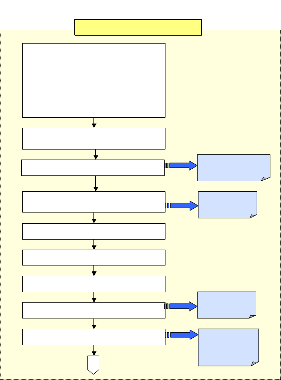
High-level I&C Process
To put the I&C activities in the context of overall system deployment, Figure 4 provides a ‘flow’
of the key activities that are performed prior to and during the installation and commissioning of
the Ripwave Base Station. Post-I&C, the system that has been installed and commissioned goes
through Acceptance Testing against the customer’s objectives for that site. Once customer sign-
off on the site is achieved, the customer becomes fully responsible for operating the system.
Different job holders may perform various portions of these activities and not necessarily all of
the activities. In fact, Marketing and Engineering personnel typically handle the earlier tasks,
while installation may be a stand-alone function. Commissioning may or may not be handled by
the same people who designed or installed the site. Regardless of who does them, these key
activities have to be accomplished for successful deployment:
?? Site Selection, Design, and Preparation
?? Physical Installation
?? Commissioning, with Acceptance Testing and Sign-off
Prior to installation, Navini and the customer formulate a Project Plan and Responsibility
Assignment Matrix (RAM) to clarify who will do what to complete the I&C activities. If
requested by the customer, Navini may provide personnel, procedures, forms, and/or tools
required to install and commission the Base Station equipment. They may also provide special
commissioning software programs, computers, and any other special test equipment required.
As part of the I&C duties, all testing results are recorded and kept for the customer to review and
approve. These test results include the cable sweeps, the BTS Calibration Verification, RF
System Tests, Drive Study, Line-of-Sight (LOS) FTP tests, and Non-Line-of-Sight (NLOS) FTP
test results. The I&C Supervisor provides site tracking and weekly status reports. All of these
tasks can be negotiated with the customer.
If Navini Networks is hired by a customer to provide Installation & Commissioning Services,
involvement and some actual deliverables are still required by the customer. For example, the
customer will need to review or perhaps even explain their Site Design Specifications, approve
Logistics Plans, provide shipping information, approve the Network Architecture Plan, etc.
As part of a successful hand-off from Navini to the customer, it is usually necessary for Navini to
provide some product training to customer personnel who will support the Base Station operation
on-going. Customers may opt to take on a Train-the-Trainer program, in which case Navini
certifies the customer’s instructors who then provide staff training thereafter.
Ripwave Base Station I&C Guide Navini Networks, Inc.
Chapter 1
24 Part #40-00047-01 Rev F v1.0 (TTA)
October 23, 2003
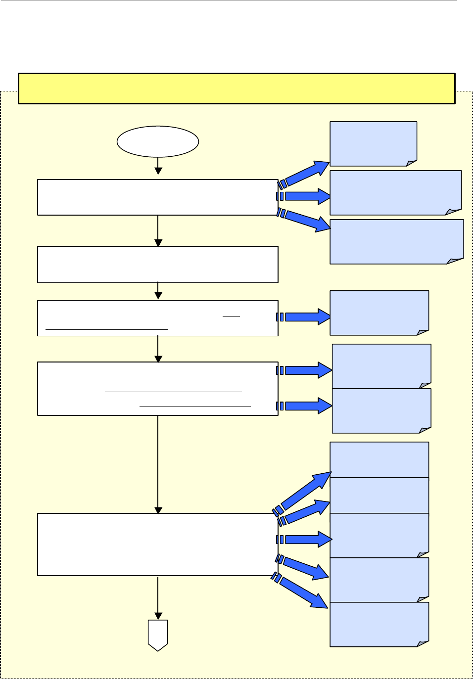
Figure 4: High Level I&C Process Flowchart
Phase I: Pre-installation - Site Selection, Design & Preparation
1
-
Complete the Project Plan for this
deployment. <Program or Project Manager>
2
-
Generate a coverage prediction map.
<RF Engineering>
3
-
Conduct a site survey, filling out the
Site
Candidate Evaluation Form.
4
-
Complete the
Interference Analysis,
following the Interference Sweep Procedure or,
if available, using the Interference Sweep Tool.
5
-
Acquire information about the final site
selected by the customer. Physical site design
completed.
Appendix D:
Site Candidate
Evaluation Form
Appendix E:
Interference Sweep
Procedure
Appendix F:
Interference Sweep
Tool
Appendix A:
Sample Statement
of Wor
k (SoW)
Appendix B:
Sample Responsibility
Assignment Matrix (RAM)
Appendix C:
Sample Work Breakdown
Structure (WBS)
Appendix G:
BTS Specifications
Appendix H:
RFS Data Sheets
Appendix I:
BTS Outdoor
Enclosure Mfrs.
Appendix J:
Rectifier/BBU
Manufacturers
A
BEGIN
Appendix K:
Sample Base Station
Drawing
Navini Networks, Inc. Ripwave Base Station I&C Guide
Chapter 1
Part #40-00047-01 Rev F v1.0 (TTA) 25
October 23, 2003
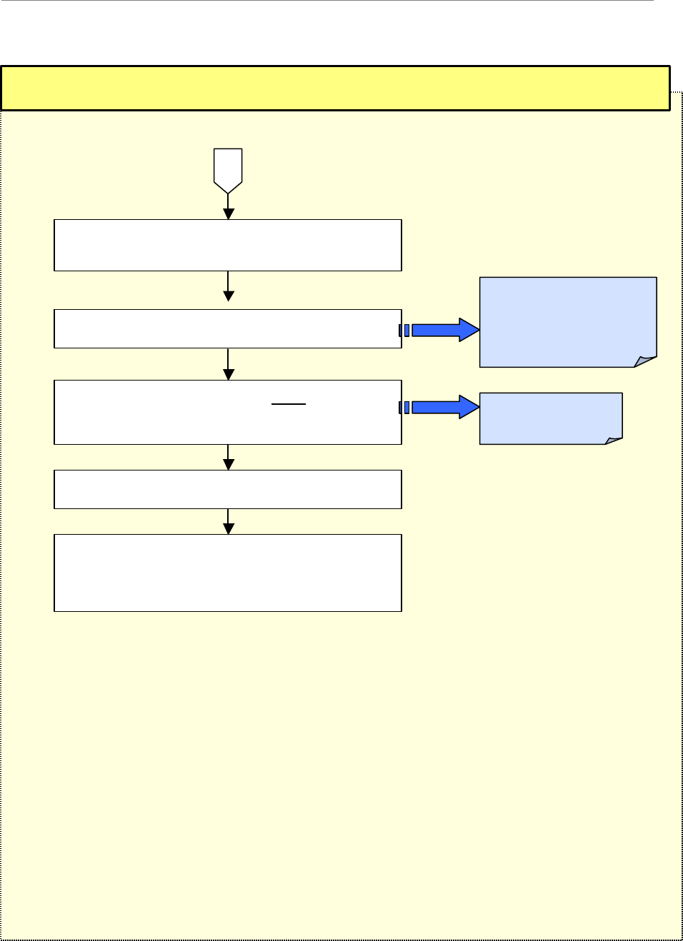
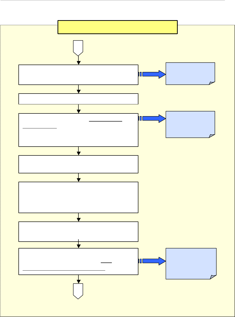
Phase I: Pre-installation -
Site Selection, Design & Preparation, continued
6
-
Complete the Network Architecture design.
<Network Planning>
8
-
Develop a Bill of Materials (
BoM
).
<Customer >
9 - Acquire the materials. <Customer>
10
-
Confirm the customer backhaul, EMS
Server, FTP Server, input power and
grounding are installed and operational at site.
Appendix M:
Sample BoM
7 - Antenna Power & Cable selection.
A
Appendix L:
Antenna Power & Cable
Selection Procedure &
Form
Ripwave Base Station I&C Guide Navini Networks, Inc.
Chapter 1
26 Part #40-00047-01 Rev F v1.0 (TTA)
October 23, 2003
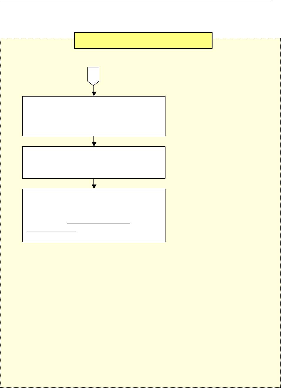
Phase II: Installation
1
-
From the shipping containers received at
the customer site, gather Manufacturing’s
inventory sheet and test data that was collected
before the BTS & RFS equipment shipped.
Verify all equipment arrived (inventory it),
serial numbers match paperwork, and the test
data is available. Keep this as part of the
customer site records.
2
-
Install all system buss bars and surge
protectors.
4
-
Instal
l & sweep the RF cables. Record
results on the RFS System Test Form.
5 - Install & sweep the GPS cables.
6 - Test & install the data/power cable.
7 - If required, install the BTS mounting rack.
8 - Install the BTS chassis.
Appendix O:
RFS System
Test
Appendix Q:
Sample Tri-sector
BTS Grounding
Drawing
9 - Install & verify the BTS & RFS grounding.
A
3 - Cut cables. Install connectors on cables. Appendix N:
Install Connectors
Appendix P:
Chassis Alarms
Information
Navini Networks, Inc. Ripwave Base Station I&C Guide
Chapter 1
Part #40-00047-01 Rev F v1.0 (TTA) 27
October 23, 2003
Phase II: Installation, continued
10
-
Install & verify the DC input power
source to the BTS.
11
-
Install the GPS antennas.
12
-
Sweep the RFS, per the
Single Antenna
Test Procedure. Record the results & the RFS
serial numbers on the RFS System Test Form
(same form as Step 3, Appendix O).
13
-
Install the RFS & surge protectors and
Connect cables to the RFS.
14
-
Sweep the installed RFS & cables to
verify connections & cable loss. Record results
on the RFS System Test Form (same form as
Steps 3 & 11, Appendix O).
15
-
Verify that the digital cards & RF/PA
cards are installed and seated properly.
16
-
Record the serial & version numbers of
the digital and RF/PA cards on the Base
Station Installation Certification Form.
Appendix R:
Sample Tri-sector
BTS Power Drawing
Appendix T:
Base Station
Installation
Certification Form
B
A
Appendix S:
Single Antenna Test
Procedure
Ripwave Base Station I&C Guide Navini Networks, Inc.
Chapter 1
28 Part #40-00047-01 Rev F v1.0 (TTA)
October 23, 2003
Phase II: Installation, continued
17
-
If required in the Responsibility
Assignment Matrix (RAM) portion of the
Project Plan, test the backhaul to the customer
demarcation point.
18
-
Provide a printed package of the measured
results and equipment inventory to the
customer on-site.
19
-
Go over the results using the printed
package and obtain customer sign-off on the
completion of the Installation portion of the
work. Use the Base Station Installation
Certification Form for sign-off (same form as
Step 15, Appendix T).
B
Navini Networks, Inc. Ripwave Base Station I&C Guide
Chapter 1
Part #40-00047-01 Rev F v1.0 (TTA) 29
October 23, 2003
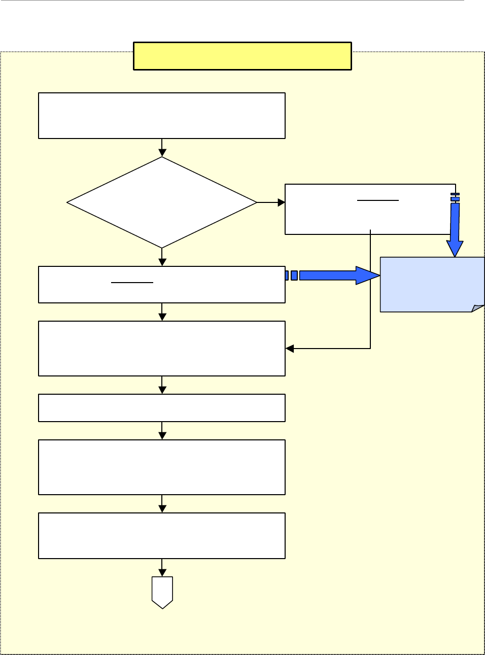
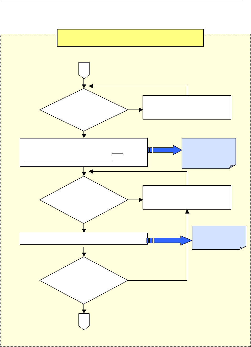
Phase III: Commissioning
1
-
Review the customer’s network plans
-
i.e.,
T1 vs Ethernet backhaul.
3b
-
Install &
configure
the customer EMS
Server & Client. Connect to the BTS.
4
-
Enter the RFS configuration by running the
RFS script that shipped with the antenna
equipment.
2
-
Are you using
the customer’s
EMS Server?
No
Yes
3a
-
Install &
configure
the
Test EMS Server & Client.
Connect to the BTS.
Appendix U:
Excel Configuration
Form
5 - Verify that all cables are connected.
6
-
Power up the BTS & reconfigure the basic
Boot Line parameters through the serial port
on the CC card.
7
-
After the B
TS has been powered up at least
15 minutes, perform 3 calibrations.
A
Ripwave Base Station I&C Guide Navini Networks, Inc.
Chapter 1
30 Part #40-00047-01 Rev F v1.0 (TTA)
October 23, 2003
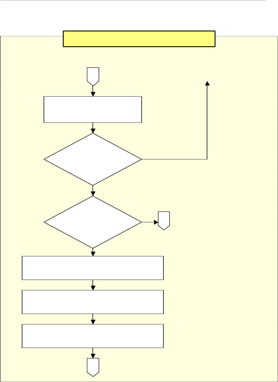
Phase III: Commissioning, continued
9b
-
Perform Base Station calibration. Verify
and record the measurements on the Base
Station Calibration Verification Form.
8
-
Did it pass
calibration? No
Yes
9a
-
Perform sys
tem
troubleshooting procedures.
Appendix V:
Base Station
Calibration
Verification Form
11b
-
Perform local wired Modem test.
B
A
10
-
Did it pass
calibration
verification?
No
Yes
11a
-
Perform system
troubleshooting procedures.
12
-
Did it pass
the wired
Modem test?
No - Go to 11a
Yes
Appendix W:
Local Modem Test
Procedures
Navini Networks, Inc. Ripwave Base Station I&C Guide
Chapter 1
Part #40-00047-01 Rev F v1.0 (TTA) 31
October 23, 2003
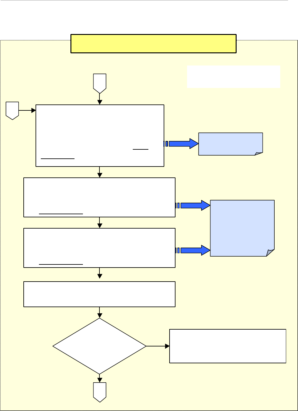
Phase III: Commissioning, continued
14
-
Did it pass
the OTA
Modem test?
Yes
13
-
Perform the local over
-
the-air (OTA) Modem test.
16
-
Install & confi
gure the Customer EMS
Server & Client. Connect to the BTS.
D
B
No
Yes
15
-
Was the
Test EMS
used?
No - Go to 11a
C
17
-
Verify the EMS Server & BTS
connectivity.
18
-
Perform calibration. Ensure successful
results 3 times.
Ripwave Base Station I&C Guide Navini Networks, Inc.
Chapter 1
32 Part #40-00047-01 Rev F v1.0 (TTA)
October 23, 2003
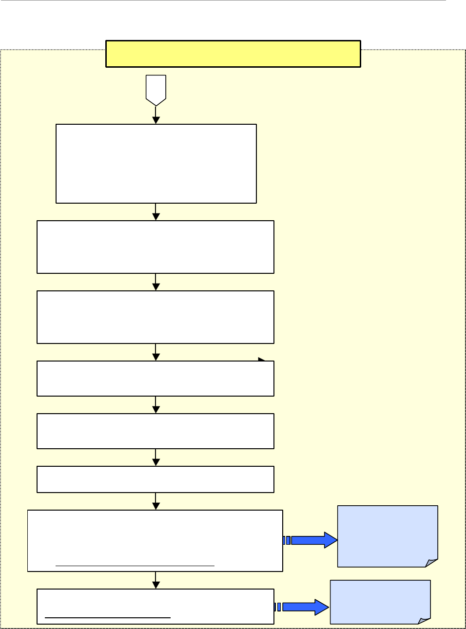
Phase III: Commissioning, continued
Yes
19*
-
Validate that the GPS &
Constellation Debugger are installed
and operational on the Drive Study
laptop. Perform a Preliminary Drive
Study. Record the results on the Drive
Study Form.
20
-
Perform the Preliminary LOS Location
(FTP) Test. Complete 3 uploads & 3
downloads at 3 locations. Record the results on
the FTP Test Form.
E
D
No
23
-
R
esults
adequate?
22
-
Send all preliminary test results to Navini
Technical Support for evaluation.
C
*Note: Step 19 is performed
only if no RF plot is available.
Appendix X:
Drive Study Form
Appendix Y:
Location (FTP) Test
Procedure & Form
21
-
Perform the Preliminary NLOS
Location
(FTP) Test. Complete 3 uploads & 3
downloads at 3 locations. Record the results on
the FTP Test Form.
24a
-
Adjust the RF parameters and
troubleshoot. Go back to Step 18,
Perform calibration.
Navini Networks, Inc. Ripwave Base Station I&C Guide
Chapter 1
Part #40-00047-01 Rev F v1.0 (TTA) 33
October 23, 2003
Phase III: Commissioning, continued
24b
-
Perform full Drive Study, and
record the results on the Drive Study
Form. This is used for tuning the
model (same form as Step 19,
Appendix X).
25
-
Perform full LOS Location (FTP) Test.
Record the results (same form as Step 20,
Appendix Y).
E
27
-
Send test results to Navini Technical
Support.
Appendix Z:
Site Installation
Closeout
Documentation
26
-
Pe
rform full NLOS Location (FTP) Test.
Record the results (same form as Step 20,
Appendix Y).
28
-
Verify system operation with multiple
Modems in use.
29 - Back up the EMS database.
30
-
Gather all required documents & forms to
create a delivery package for the Customer sign-
off and for the Navini Techical Support database.
See Installation Closeout Documentation.
31
-
Participate in the Customer sign
-
off of the
Customer Acceptance Form.
Appendix AA:
Customer
Acceptance Form
Ripwave Base Station I&C Guide Navini Networks, Inc.
Chapter 1
34 Part #40-00047-01 Rev F v1.0 (TTA)
October 23, 2003
Base Station Components
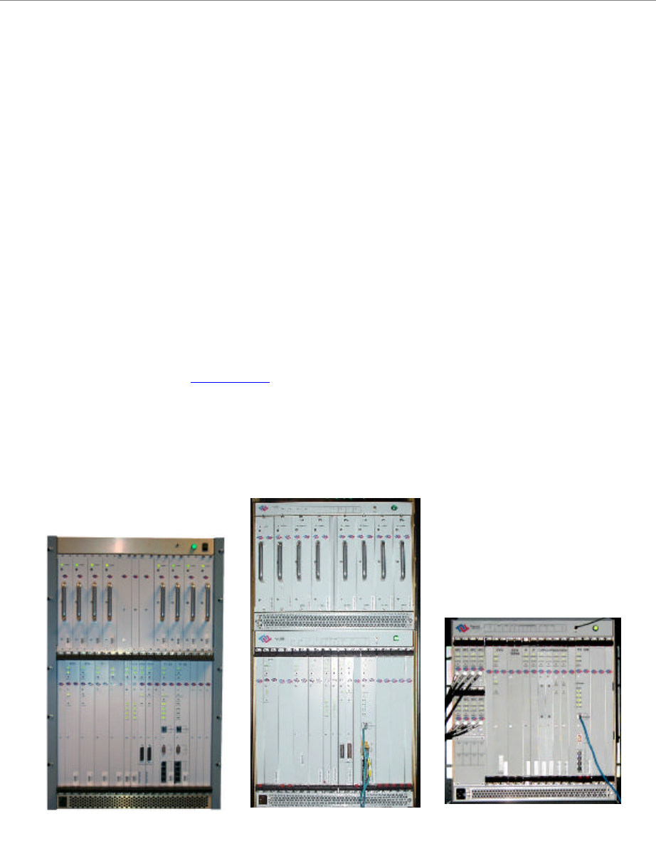
Base Transceiver Station (BTS)
The BTS consists of the RF Power Amplifiers (PAs), the digital circuit cards, the backplane, and
the mechanical enclosure or housing. It performs the signal processing and RF transmission for
the system. There are three types of chassis: Combo, Split, and Tower Top Amplifier (TTA). The
Combo Chassis is used primarily with 2.4 GHz systems. The Split Chasses is used for all other
(2.3, 2.5, 2.6 GHz) systems (Figure 5). The TTA is the latest chassis design, and is available at
this time for 2.4 and 3.5 GHz systems.
The chassis is compartmentalized into two sections - the RF shelf and the Digital shelf. The BTS
connects to the network using a 10/100 Base-T Ethernet connection or up to 8 T1 interfaces. Up
to three BTS assemblies can be installed per system, depending on the configuration. The BTS
specifications are provided in Appendix G.
Figure 5: BTS Chassis
Combo Chassis
Split Chassis
RF/PA ShelfDigital Shelf
TTA Chassis
Combo Chassis
Split Chassis
RF/PA ShelfDigital Shelf
TTA Chassis
Navini Networks, Inc. Ripwave Base Station I&C Guide
Chapter 1
Part #40-00047-01 Rev F v1.0 (TTA) 35
October 23, 2003
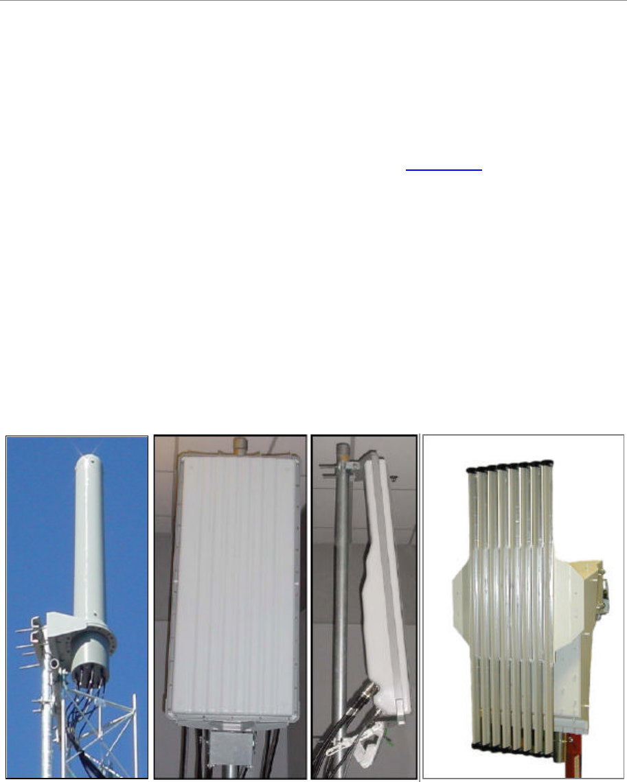
Radio Frequency Subsystem (RFS)
The Radio Frequency Subsystem (RFS) is mounted on a transmission tower or building rooftop.
It transmits and receives data to and from the Ripwave Customer Premise Equipment (CPE)
using a digital beamforming transmission technique. The RFS may be either a panel antenna or
an omni antenna (Figure 6). The RFS data sheets are provided in Appendix H.
An RFS panel transmits in a directional mode, covering a transmit angle of 120 degrees. The
antenna can be used as a single mode antenna, or it can be used in a group of two or three
sectored antennas, covering 240 and 360 degrees respectively. Each panel requires a BTS to
operate. For example, in a tri-sectored cell with 3 panels, you would need 3 BTSs. The omni
antenna provides omni-directional coverage of 360 degrees.
An RFS panel or omni contains eight (8) antenna elements, cavity filters, and, optionally, low
noise amplifiers (LNA). In the TTA configurations, the PAs also are located in the RFS
(antenna) by the LNAs and cavity filters.
Figure 6: RFS
Omni Panel (front) Panel (side) 3.5 GHz TTA PanelOmni Panel (front) Panel (side) 3.5 GHz TTA Panel
Ripwave Base Station I&C Guide Navini Networks, Inc.
Chapter 1
36 Part #40-00047-01 Rev F v1.0 (TTA)
October 23, 2003
Global Positioning System (GPS)
One Global Positioning System (GPS) antenna is used with each Base Station to provide a
timing signal for synchronizaton. A second GPS antenna can be provided for redundancy. The
Ripwave Base Station uses the VIC 100 GPS Antenna (Figure 7).
Figure7: VIC 100 GPS Antenna
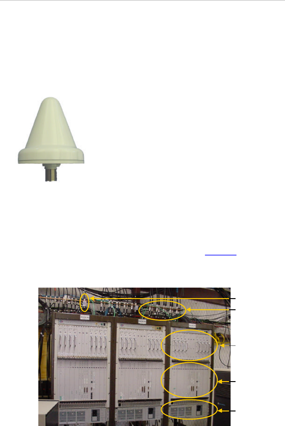
Mounting Racks & Enclosures
The BTS can be installed indoors or outdoors in industry standard 19- or 23-inch racks. Rack
adapters are needed to mount the equipment in a standard 23-inch rack. For outdoor BTSs, the
customer can supply any standard enclosure from a multitude of vendors. Appendix I offers
suggestions for outdoor BTS enclosures. Figure 8 shows 3 BTSs installed indoors.
Figure 8: Indoor BTS (Combo Chassis)
Buss bar with
PSX surge
arrestors for RF
& Cal cables
RF Shelf
Digital Shelf
Rectifiers
Surge arrestor
for GPS cable
Buss bar with
PSX surge
arrestors for RF
& Cal cables
RF Shelf
Digital Shelf
Rectifiers
Surge arrestor
for GPS cable
Navini Networks, Inc. Ripwave Base Station I&C Guide
Chapter 1
Part #40-00047-01 Rev F v1.0 (TTA) 37
October 23, 2003
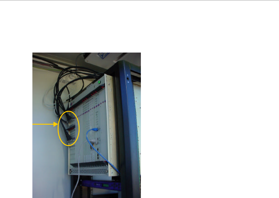
Figure 9: Indoor BTS (TTA Chassis)
Accessibility
Ripwave BTS equipment is required to be installed in a restricted access location, in accordance
with NEC/CEC standards. Only authorized personnel should have access to this equipment.
QMA
connectors
QMA
connectors

Ripwave Base Station I&C Guide Navini Networks, Inc.
Chapter 1
38 Part #40-00047-01 Rev F v1.0 (TTA)
October 23, 2003
Technical Specifications
Table 3a: Technical Specifications
Combo Split TTA
Frequency Band (GHz) 2.4 2.6 2.3
2.5, 2.6 2.4 3.5
Frequency Band (Name) ISM MMDS WCS
ITFS/MMDS ISM WCS
Frequency Range (GHz) 2.400–
2.473 2.602–
2.637 2.305–2.385
2.500–2.596 2.400–
2.483 3.400–
3.700
TTD
1:1 560 850 850 292 292
Watt TTD
3:1 725 1150 1150 360 360
TTD
1:1 1910 2900 2900 1000 1000
Power Dissipation
(Thermal Load ) BTU
per
hour TTD
3:1 2475 3925 3925 1230 1230
Rectifier Rating (Watt)* 975 1,500 1,500 580 580
Circuit Breaker Rating (Amp) 60 RF Shelf : 50
Digital Shelf : 20 40 40
Input Voltage +21 to 28 VDC
Relative Humidity of BTS Operating
Environment 0% to 95% RH, non-condensing
Operating Temperature (°Celsius) 0° to +50°o
Storage Temperature (°Celsius) –40° to +70°
Air Flow (on each shelf) Fresh air intake along the lower front vertical panel.
Air exhaust out of the upper rear of the chassis
Downlink QPSK, 8PSK & QAM16
Modulation Uplink QPSK
Omni 2° electrical downtilt (fixed)
Antenna Downtilt 120o Panel 6° electrical downtilt (fixed) plus 0-10° mechanical uptilt
(adjustable).
Omni 12 dBi Antenna Gain
(per antenna element) 120o Panel 17 dBi
Backhaul interfaces 10/100 BaseT Ethernet or ATM over T1; up to (8) T1s with or
without IMA, long haul support
Bandwidth Allocation Dynamic
Duplex Format Time Division Duplex
RF:
14 x 19 x 15.2 Chassis Mechanical Dimensions in inches
(H x W x D) 30 x 19 x 14 Digital:
19.2 x 19 x 12.9
19.2 x 19 x 12.9
RF: 82
Chassis Weight (lb) 60 Digital: 33 36
Omni Antenna Mechanical Dimensions
(H x Diam.) in inches 60 x 15 50 x 10
Omni Antenna Weight (lb) 65 52
(continued on the next page)
*The BTS must be connected to a power supply/rectifier that is UL listed.

Navini Networks, Inc. Ripwave Base Station I&C Guide
Chapter 1
Part #40-00047-01 Rev F v1.0 (TTA) 39
October 23, 2003
Combo Split TTA
Frequency Band (GHz) 2.4 2.6 2.3
2.5, 2.6 2.4 3.5
Panel Antenna Mechanical Dimensions
(H x W) in inches 46 x 23 38 x 19
Panel Antenna Weight (lb) 64 50
Polarization Vertical
Multiple Access Scheme Multi-carrier Beamforming Synchronous CDMA
Power Control Forward & reverse, open & closed loop
Total System Capacity in Mbps (total raw
capacity with QAM16 downlink and QPSK
uplink) 11.6 12 11.6 12
Base Station Payload Data Rate in Mbps
(with QAM16 downlink and QPSK uplink;
excludes adaptive modulation based on SNR,
end to end network retransmissions and
Ethernet & IP protocol overhead)
6.0
(4.2 DL,
1.8 UL)
6.4
(4.2 DL, 2.2 UL)
6.0
(4.2 DL,
1.8 UL)
6.4
(4.2 DL,
2.2 UL)
BTS Input/Output Specifications
Table 3b: BTS Input/Output Specifications
Item Description Termination Expected
MAX
Length
Protection specified in
Manual
DC +24V
Power +21 to +28V input,
–/+ terminals Power Supply/Rectifier
customer equipment <140 FT
Rectifier must be UL-
listed, comply with
UL60950 or UL60950-1,
and have earthed SELV
output
GND Chassis Ground connection Earth Ground <140 FT GND required.
T1 T1 communication lines off CC
card
T1s interface switch
customer equipment.
Typical installation
requires DSU or CSU
providing loopback
capability and primary
Type 1 protection.
>140 FT In-Line Devices such as
DSU/CSU/TSU/PPC
must be UL497 listed
Ethernet 10/100 BaseT communication
off CC card PC/Router/HUB/Gateway <140 FT Not required
UART D sub serial connection off CC
card, used for on site
communications to PC PC <140 FT Not required
BBU
BBU connector can accept up to
4 alarm inputs plus GND. BTS
monitors alarms and reports
back to EMS condition. Inputs
come from dry contacts at the
BBU side, normally open circuit,
can be closed circuit for
alarmed condition.
BBU customer equipment.
<140 FT Not required
(continued on the next page)

Ripwave Base Station I&C Guide Navini Networks, Inc.
Chapter 1
40 Part #40-00047-01 Rev F v1.0 (TTA)
October 23, 2003
Item Description Termination Expected
MAX
Length
Protection specified in
Manual
Cabinet
Alarms
Cabinet alarms: Door open and
HMC alarms plus 2 GND inputs.
BTS monitors alarms and
reports back to the EMS
condition. Inputs come from dry
contacts in the cabinet, which
are normally open circuit, can
be closed circuit for alarmed
condition.
Cabinet customer
equipment. <140 FT Not required
TDD SYNC
TDD sync is a TTL Sync pulse
at a 10 ms cycle rate, 0 to +5V
swing, which is 5 ?s long in
width. This output of BTS is
used for equipment debugging
and to synchronize test
equipment.
Test equipment such as
oscilloscope or analyzer
equipment
<140 FT Not required
GPS
Antenna A/B
(2)
The GPS coax cable carriers
+5V DC and 1.57 GHz RF
signal to be connected to GPS
antenna LNA. RF is an input to
BTS; DC is an output from BTS.
GPS antenna/LNA, which
is normally located at BTS
or on HUT of BTS, not on
tower.
<140 FT Not required
RFS
Calibration
Cable (1)
This coax cable is an RF signal
path to the RFS. Signal is a low
power signal from 2.1 to 2.5
GHz.
RFS connection to BTS >140 FT Lightning protection
devices must be UL497
listed
RFS
Antenna
Cables (8)
These coax cables are RF
signal path to the RFS. Signal
frequency from 2.3 to 2.7 GHz.
RFS connection to BTS >140 FT Lightning protection
devices must be UL497
listed
Power/Data
Cable (1)
This cable is a 6-twisted pair
bundled cable used for sending
low current DC voltage to the
RFS at +8 to +12V as well as
RS485 digital bus for TDD
control.
RFS Connection to BTS >140 FT Lightning protection
devices must be UL497
listed