Cisco Systems BTS-R3 Broadband Data BTS User Manual chpt 3 40 00047 07 F I C TTA 1
Cisco Systems, Inc Broadband Data BTS chpt 3 40 00047 07 F I C TTA 1
Contents
Manual 7

Navini Networks, Inc. Ripwave Base Station I&C Guide
Chapter 3
Part #40-00047-07 Rev F v1.0 (TTA) 75
October 9, 2003
Chapter 3: Commissioning
This chapter provides post-installation instructions on provisioning, configuring, calibrating,
testing, and commissioning the Ripwave Base Station.
Review Customer Network Plans
As part of preparing to put the BTS into commission, it is important to review the actual installed
site against the customer Network Architecture Plan - i.e., checking that all equipment and
software are installed and available for use. Verify that all routers are installed and IP addresses
are correct. Finally, make sure the installation is approved and signed off by all responsible
parties.
Install EMS Server
The EMS is the management interface for all elements in the Ripwave system. The EMS Server
has to be installed on a computer that is connected directly to the Base Station (called the Test
EMS) or through the system backhaul (customer EMS).
For testing purposes, the Test EMS Server is connected through an Ethernet hub or switch to the
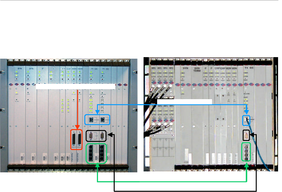
Ethernet port found on the front of the BTS (Figure 48). Note that the EMS Server does not
support more than one Network Interface Card (NIC).
The other port on the front of the CC card is a Serial (Universal Data) Port, also known as the
Console Port. Using a laptop/portable computer connected through the data port, an on-site
technician can communicate directly with the BTS using a terminal emulation software package.
However, this is not recommended. It is always best to rely on the EMS interface for BTS
information.
When connecting the Ripwave equipment to the backhaul, refer to the Regulatory Information in
Chapter 1, Page 8 – specifically regarding cabling to Ethernet or T1 backhauls. Ethernet
connections require a UL497B listed protection device to be installed between the BTS and the
first network device. T1 connections must be routed from the BTS through a UL497 listed
protection device at the demarcation point. The interconnect cables for T1 backhauls must be a
minimum #26 AWG wire, in accordance with NEC/CEC standards.
Ripwave Base Station I&C Guide Navini Networks, Inc.
Chapter 3
76 Part #40-00047-07 Rev F v1.0 (TTA)
October 9, 2003
Figure 48: Ports on CC and MDM Cards
If the customer’s EMS is installed and can be accessed through the backhaul, it can be connected
via T1 or Ethernet to the BTS and used for testing purposes. The EMS software installation
procedures can be found in the EMS Software Installation Guide, P/N 40-00017-00.
After the EMS Server and Client applications are installed, the EMS database needs to be
configured with the settings that are designated for the Base Station. The settings are found in the
Network Architecture Plan provided by the customer.
Verify Cable Connections
Before proceeding, verify that all power is connected and present. Ensure that all T1 or Ethernet
connections are installed correctly and are active. Verify that the BTS and the RFS are properly
installed and that all cables are connected.
Combo/Split Chassis TTA
Serial Port (a.k.a. Console Port)
T1 Connectors
Ethernet Connectors
Serial Ports (factory use only)
Combo/Split Chassis TTA
Serial Port (a.k.a. Console Port)
T1 Connectors
Ethernet ConnectorsEthernet Connectors
Serial Ports (factory use only)Serial Ports (factory use only)

Navini Networks, Inc. Ripwave Base Station I&C Guide
Chapter 3
Part #40-00047-07 Rev F v1.0 (TTA) 77
October 9, 2003
Configure & Power Up the BTS
Overview
During initial power up a minimal set of configuration parameters have to be input to the BTS
through the serial port on the CC card. These early configuration parameters are referred to as
the “boot parameters”. They are required to get the BTS to communicate with the EMS Server so
that all the configuration data can be downloaded from EMS to the BTS.
The PC used at this point is a Test EMS Server (i.e., laptop). If the customer’s actual EMS
Server is available, a separate Test EMS (i.e., laptop) may not be necessary. For simplification,
whether it is a Test EMS laptop or the customer’s EMS Server, we refer to the device at this
stage as the Test EMS.
Set Up the Test EMS
Typically, in order to keep a constant link an Ethernet hub (10/100 Base-T) connects the Test
EMS to the BTS via a male to female RS-232 cable connected to the CC serial port. A
connection between the serial port on the CC and the serial port on the Test EMS is also used.
Standard communication software, i.e., a standard terminal emulation program, such as Windows
HyperTerm or TeraTerm, is used during these early configuration stages.
Step 1. Verify all RF cables going to the BTS are securely connected to the proper connector.
Step 2. Connect an Ethernet cable to the Ethernet connector located on the CC card and to an
Ethernet hub. Connect another Ethernet cable from the Ethernet hub to the Ethernet
connector on the PC containing the Test EMS Server and Client applications.
Step 3. Connect an RS-232 cable (DB-9 male to female) to the serial port (UART) located on
the CC card to the serial port connector on the Test EMS computer.
Note: A VT 100 terminal or any standard Windows based ASCII terminal emulation
program can be used for connecting to the serial port. The connection for
HyperTerminal is explained here. The steps to get to the HyperTerminal program may
be different due to variances in the Operating Systems and in the setup of the PC.
Step 4. Power on the Test EMS Server.
Step 5. On the desktop, go to Start > Programs > Accessories > HyperTerminal >
HyperTerminal (using whichever terminal emulation program you are running).
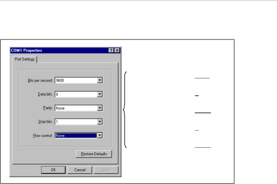
Step 6. In the COM1 Properties window (Figure 49), under the Port Settings tab, enter the
following configuration options. Click OK.
Ripwave Base Station I&C Guide Navini Networks, Inc.
Chapter 3
78 Part #40-00047-07 Rev F v1.0 (TTA)
October 9, 2003
Figure 49: COM1 Properties
Step 7. On the Test EMS Server, click on the Server icon to start the EMS Server. NOTE: This
step assumes you have loaded and configured the EMS Server & Client applications.
Step 8. Click on the EMS Configuration & Alarm Manager (CAM) icon to start the EMS
Client GUI.
Step 9. At the EMS Configuration & Alarm Manager login screen, enter the user name and
password. The defaults are both emsAdmin.
Add BTS in EMS
Once you have the CAM application running on the Test EMS server, you will need to click on
the BTS element tab to add the new BTS. Only the minimal configuration parameters have to be
completed at this time - i.e., BTS name, ID, IP address, subnet mask, and gateway. Follow the
Network Architecture Plan designed for this system.
Also configure the GPS offset time. The default is 0 minutes, indicating the BTS would be
located in the same time zone as Greenwich Mean Time (GMT). Change this value to whatever
time is appropriate to the location of the BTS in relation to GMT time zone. For example, if the
BTS is located in Dallas, Texas, which is 6 hours behind GMT time zone, you would enter –360.
As you will see in the section that follows, you will also configure the RFS splitter loss at this
time. For more details about configuring a BTS, refer to the Ripwave Configuration Guide.
Bits per second: 9600
Data Bits: 8
Parity: None
Stop Bits: 1
Flow Control: None
Bits per second: 9600
Data Bits: 8
Parity: None
Stop Bits: 1
Flow Control: None

Navini Networks, Inc. Ripwave Base Station I&C Guide
Chapter 3
Part #40-00047-07 Rev F v1.0 (TTA) 79
October 9, 2003
Configure RFS (Splitter Loss Value)
Each RFS shipped is pre-programmed for the customer’s specific operating environment. An
RFS Configuration CD accompanies the RFS equipment when it is shipped. The CD includes an
RFS script and a Quick Guide with procedures on selecting the appropriate splitter loss values to
be entered into the EMS database for the given Base Station. Each Configuration disk is unique
to the individual RFS that is shipped. You cannot use the same disk on other RFS equipment.
RFS Configuration Procedure
Step 1. Remove the RFS Configuration disk from the RFS packaging, and insert it in the
floppy drive of the Test EMS.
Step 2. Copy the folder named “RFS” that is on the disk to the Test EMS Server:
<ems install dir>/scripts.
It will take approximately 20 seconds to complete.
Step 3. Open the new folder on the EMS server. You will see a list of file names. The format
of the file names is as follows:
RFS_serial number_frequency.cli
Example: “RFS_024300001_2402500.cli” - This example of the configuration file is
for an RFS with serial number 024300001 and a center frequency of 2.4025.
Verify the correct serial number in the file name against the serial number of the RFS
equipment. The equipment serial number may be found on the back of the RFS panel
or on the side of the bottom cylinder of the omni antenna.
Step 4. Determine which file you need to run, depending on the provisioned frequency of your
BTS.
NOTE: For 2.6 GHz systems, select the frequency that is closest to your provisioned
center frequency. To find the provisioned center frequency for your BTS, open the
EMS Configuration & Alarm Manager (CAM) application. Select the BTS tab and
specific BTS, then Air Interface / Layer 2 / Carrier Data / Show Configuration. This
will display the center frequency information.
Step 5. Open the selected CLI file for editing using any text processing application program.
Note the power splitter values listed there (i.e., write them down or print them out).
Step 6. Modify the line that starts with “bts” by changing the BTS ID for your BTS. The
default is “BTS 1”. For example, if the ID for your BTS is 252, change the “1” to
“252”.

Ripwave Base Station I&C Guide Navini Networks, Inc.
Chapter 3
80 Part #40-00047-07 Rev F v1.0 (TTA)
October 9, 2003
Step 7. Save this file as text, and then close it.
Step 8. Start the EMS Config CLI application to run “script <CLI script>”. Do this by entering
the following:
>enable <user name> <password>
>configure
>script scripts/rfs/rfs_<serial number>_<7-digit frequency>.cli
NOTE: For Unix operating systems, the CLI text is case sensitive and the slash marks
should be backward slashes instead of forward slashes.
Step 9. View the Power Splitter values in EMS to verify that the CLI script ran as expected.
The Power Splitter values may be found under Layer 1 / Show Configuration >
Antenna Table. You will need to “Refresh” the active screen to view the updated
information.
Step 10. Type “Exit” twice to exit the Config CLI edit mode.
Power Up BTS
Now you are ready to power up the BTS.
Step 1. Ensure that input power has been connected to the BTS.
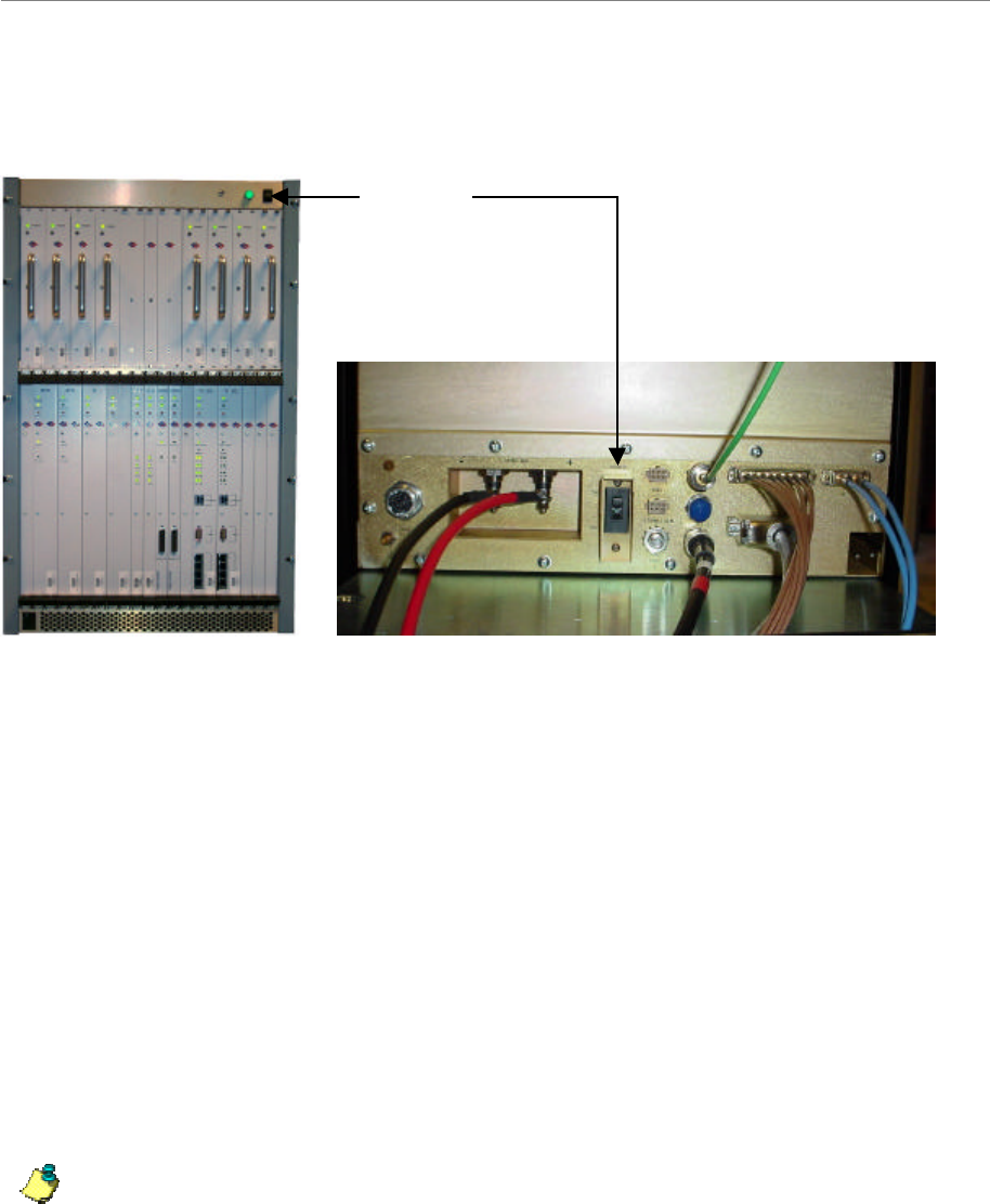
Step 2. Switch the Power to ON. If the BTS is a Combo Chassis, the switch is located on the
top right front of the BTS. The green Power On light next to the switch will illuminate
(Figure 50).
If the BTS is a Split Chassis, the Power ON switch is located on the back lower middle
of the Digital shelf. The green LEDs on the RF/PA modules and the circuit cards in the
BTS chassis should illuminate.
The Power switch for the TTA is located on the lower middle back of the chassis.
Navini Networks, Inc. Ripwave Base Station I&C Guide
Chapter 3
Part #40-00047-07 Rev F v1.0 (TTA) 81
October 9, 2003
Figure 50: BTS Power On Switches
Step 3. Watch for the auto-boot countdown command. Type in config on the computer
keyboard to interrupt the standard boot sequence. The window of time to type in
“config” after auto-boot starts is 20 seconds.
BTS Bootup
The BTS is shipped with a default value of a 20-second countdown to interrupt the standard
bootup sequence. You can escape the standard bootup when the display shows the following:
autoboot countdown : quick [quick|delayed]
To escape the initialization sequence, type in config before the 20-second counter reaches zero.
Note: Under the next section, “Boot Prompt”, you will see how to disable the 20-second
countdown in lieu of a shorter, 1-second countdown. This will minimize downtime
during unattended restart conditions, for example, if there is a power outage and the BTS
is recovering.
Off/On switch
Power
ON/OFF
Combo Chassis
Split Chassis
Off/On switch
Power
ON/OFF
Combo Chassis
Split Chassis

Ripwave Base Station I&C Guide Navini Networks, Inc.
Chapter 3
82 Part #40-00047-07 Rev F v1.0 (TTA)
October 9, 2003
Boot Prompt
After you have escaped from the automated boot sequence, the console will display a
rudimentary Boot prompt:
[Navini Boot]:
This prompt offers the ability to perform a small set of operations. Enter ‘?’ or ‘h’ followed by
the Enter key to display a list of commands (Exhibit 1). To invoke any of the commands, simply
enter the single letter command with optional parameters, followed by the Enter key.
.
Exhibit 1: Boot Commands
[Navini Boot]: ?
? - print this list
@ - resume boot sequence
p - print boot params
c - change boot params
d adrs[,n] - display memory
m adrs - modify memory
f adrs, nbytes, value - fill memory
t adrs, adrs, nbytes - copy memory
@ – Use this command once all parameters have been set as desired. This will resume the boot
initialization sequence that you escaped from previously.
p – This command displays a concise representation of the current parameters used for boot
configuration.
c – Use this command to alter the current boot parameters. Once selected, a detailed sequence of
options is prompted, and is covered in detail later. After all of the items in this list are completed,
you return to the [Navini Boot]: prompt. This option sequence allows you either to accept the
current value by pressing the Enter key or to enter a new value from the range or values listed,
followed by the Enter key. Additionally, you can enter ‘.’ followed by the Enter key to erase the
current value of an item and return it to a default state. If you make an error, you can choose ‘-‘
(hyphen) followed by the Enter key to return to the previous item in the list. Alternatively, you
can fix an error by proceeding with the selections and select ‘change' when you return to the
[Navini Boot]: prompt.
d – Display memory allows you to display portions of the BTSs memory with user-defined
values. It should only be performed with the assistance of a certified Navini service technician.
m – Modify memory allows you to alter portions of the BTSs memory with user defined values.
It should only be performed with the assistance of a certified Navini service technician.

Navini Networks, Inc. Ripwave Base Station I&C Guide
Chapter 3
Part #40-00047-07 Rev F v1.0 (TTA) 83
October 9, 2003
f – Fill memory allows you to alter portions of the BTSs memory with a fixed pattern. It should
only be performed with the assistance of a certified Navini service technician.
t – Fill memory allows you to alter portions of the BTSs memory with a pattern from another
area of memory. It should only be performed with the assistance of a certified Navini service
technician.
Ethernet Configuration
The Ethernet configuration is grouped into three sections: general, EMS, and traffic path. An
example of the Ethernet configuration parameters is shown in Exhibit 2.
Exhibit 2: Ethernet Configuration
[Navini Boot]: p
date and time : 01/09/2003[10:19] MM/dd/yyyy[hh:mm]
autoboot countdown : delayed [quick|delayed]
ems inet : 172.16.0.10
snmp community : public
traffic path : enet [enet|atm]
mac address : 00:04:6a:00:01:20
ip on enet (active) : 172.16.23.181
ip on enet (standby) : 172.16.23.182
netmask on enet : 255.255.0.0
ip on backplane : 10.0.0.1
gateway on enet : 172.16.0.100
General
The general section offers you the ability to change the date and time manually. If a GPS has
been installed, the BTS will automatically set the date and time:
date and time : 08/21/2002[13:21] MM/dd/yyyy[hh:mm]
When this line is displayed, the current date (08/21/2002) and time [13:21] are displayed. Accept
the defaults by pressing the Enter key, or enter “date” at the console and a new value using the
format indicated in military time (Hours 1-24). All 5 fields must be entered as specified. Leading
zeroes can be omitted.
Previously, it was mentioned that the 20-second auto-boot countdown timer can be disabled and
a 1 second countdown can be used instead. To enable this feature, change the autoboot
countdown item from “delayed” (which is 20 seconds) to “quick”, which is 1 second:
autoboot countdown : delayed [quick|delayed]

Ripwave Base Station I&C Guide Navini Networks, Inc.
Chapter 3
84 Part #40-00047-07 Rev F v1.0 (TTA)
October 9, 2003
EMS
This section concerns the configuration of the EMS Server itself. First, the Internet (inet) IP
address of the Server is specified. Make sure to fill this field with the address of the Server used
to configure this BTS. Your BTS is shipped with this field un-initialized. You must provide a
valid 4-digit IP address before you can proceed. For example:
ems inet : 172.16.0.10
The second parameter that you must specify to allow the EMS Server to recognize this BTS is a
community string for the EMSs Simple Network Management Protocol (SNMP) interface. The
default community string shipped with the BTS is “public”. Press the Enter key to accept this
default, or type in a new value and press the Enter key to alter it:
snmp community : public
Traffic Path
The last major block of configurations required for an Ethernet backhaul to the BTS is the traffic
path parameters. The first prompt instructs the BTS to use the Ethernet as the WAN (backhaul)
configuration. It must be set to “enet” for an Ethernet backhaul.
If “atm” is selected, proceed with the description in the ATM or IMA sections. The BTS is pre-
configured to use Ethernet for the WAN connection. Press the Enter key to accept this default:
traffic path : enet [enet|atm]
The BTS address is specified next. Every BTS must be uniquely addressed and have values that
equate in the EMS configurations. This address information defines the Layer 2 parameters first,
and then it defines the Layer 3 parameters. For Layer 2, you are only given an opportunity to see
the Ethernet Media Access Control (MAC) address used by this BTS. This is a unique number
programmed in the BTS. You cannot alter it. However, situations may develop in which you
need to know the MAC address and, therefore, need to display the information. For example:
mac address : 00:04:6a:00:01:20
Next are the IP addresses that represent this BTS: one for the active CC card and one for the
standby CC card. Enter the IP for the active controller card, for 172.16.23.181, and the next IP
(172.16.23.182) is automatically assigned to the Standby card.
ip on enet (active) : 172.16.23.181
ip on enet (standby) : 172.16.23.182

Navini Networks, Inc. Ripwave Base Station I&C Guide
Chapter 3
Part #40-00047-07 Rev F v1.0 (TTA) 85
October 9, 2003
The standby field is only displayed for your convenience and cannot be altered. Note that the
BTS automatically handles switching the address when a failure occurs on an active Controller
card, requiring the standby Controller to go into service. However, the MAC addresses remain
fixed.
Coupled with any IP configuration is a need to specify the corresponding subnet mask. Refer to
common network administration literature for guides on addresses, networks, masks, and
gateways. In short, the subnet mask identifies the portion of the IP address that is common to
those devices connected to the same Ethernet. The most important “other” device is the BTSs
default gateway (specified later).
The portion is identified using a logical “and” of the mask with the address. For example, a
subnet mask of 255.255.0.0 and with an IP address of 172.16.23.182 yields a network of
172.16.x.x. In this case, the default gateway must also be on the 172.16.x.x network. The BTS
requires that this association be met. If not, you will be asked to try again.
netmask on enet : 255.255.0.0
The BTS uses a high-speed Serial Line Internet Protocol (SLIP) connection to communicate with
the redundant T1/Controller Card. This interface is only used internally and has a fixed subnet
mask of 255.255.255.252.
The host portion of the address –that is, the least significant 2 bits– is automatically provided by
the software based upon slot ID. However, you may want to alter the default network address to
avoid conflict with your network.
The BTS is shipped with the 10.0.0.0 network as the internal network. This is a reserved network
not used on the Internet. However, if your private network utilizes this private address space, you
may need to change it to avoid the conflict.
ip on backplane : 10.0.0.1
As for the default gateway for the BTS, all traffic routed outside the directly connected Ethernet
port goes through the gateway. Furthermore, the gateway must be reachable on the directly
connected Ethernet port. Therefore, the BTS will prevent you from entering a default gateway
address that fails the logical “and” test discussed previously. This address is specified on the line
item shown below:
gateway on enet : 172.16.0.100

Ripwave Base Station I&C Guide Navini Networks, Inc.
Chapter 3
86 Part #40-00047-07 Rev F v1.0 (TTA)
October 9, 2003
ATM/T1 Configuration
For an ATM/T1 configuration, the items shown in Exhibit 3 are identical to Ethernet with the
exception of the traffic path, which must show “atm” for this type of configuration.
Exhibit 3: ATM/T1 Configuration
date and time : 01/09/2003[10:22]
autoboot countdown : delayed
ems inet : 172.16.0.10
snmp community : public
traffic path : atm
mac address : 00:04:6a:00:01:20
ip on atm (active) : 172.16.23.181
ip on atm (standby) : 172.16.23.182
netmask on atm : 255.255.0.0
When ATM is selected for the WAN interface using the traffic mode parameter, an additional set
of parameters is required (Exhibit 6). First of all, another IP address must be identified for the
ATM interface. The ATM IP address cannot be the same as the Ethernet IP address. In this case,
the Ethernet IP address is only used for debug purposes and is a non-routed interface. This means
that the BTS can only reach other computers directly connected to the Ethernet port of the BTS.
The only routed interface available is through the ATM port. This routed interface address is
specified with the “ip on atm” line item and the corresponding netmask parameter (Exhibit 4).
The information on network address specifications from the Ethernet Configuration section of
this chapter applies to ATM as well. For ATM, the only gateway allowed for the BTS is on the
ATM interface, as specified here.
Exhibit 4: Additional ATM Parameters
ip on atm (active) : 172.17.0.101
ip on atm (standby) : 172.17.0.102
netmask on atm : 255.255.0.0
ip on backplane : 10.0.0.1
gateway on atm : 172.17.0.100
For an ATM system, the BTS must have some additional configuration for the Management
Private Virtual Channel (Management PVC). Recall the boot parameter philosophy discussed
before. The boot parameters only identify those settings required to allow the BTS to reach the
EMS. Note that the boot parameters only allow specification for one PVC (the Management
PVC), which is used to reach the EMS.
All user traffic PVC parameters are specified in the EMS configuration. Ensure that the EMS
parameters for the Management PVC match those being set here through the boot prompt. If not,
as soon as connection is made with the EMS, the Management PVC will be reconfigured and can
potentially disconnect the BTS from the network.

Navini Networks, Inc. Ripwave Base Station I&C Guide
Chapter 3
Part #40-00047-07 Rev F v1.0 (TTA) 87
October 9, 2003
The PVC configuration is broken into 3 sections: ATM layer parameters; optional Inverse
Multiplexing over ATM (IMA) parameters, and T1 physical layer parameters. The first item
selects which ATM interface will be used for the Management PVC. If IMA is not selected, you
may select from one of the 8 T1 ports numbered 1-8 using the option t1-N, where N is the port
number. This is the same interface port number specified in the EMS. If IMA is desired,
reference the following section:
pvc type-atm i/f : t1-0 [t1-(1-8)|ima-(1-2)]
The circuit identifier for this segment of the Management PVC is the next item specified. The
first parameter identifies the maximum number of bits for any PVCs identifier Virtual Path
Identifier/ Virtual Channel Identifier (VPI/VCI) pair. The BTS restricts the available set to 13
total bits. However, you are free to divide those 13 bits between the VPI and VCI as needed,
with the VPI having a maximum allocation of 8 bits. You can choose the number of bits for each
by selecting two values separated by a “:”. Or you may select the BTS default of 3 VPI bits and
10 VCI bits by pressing the Enter key:
pvc id size vpi:vci : 3:10 [1-8:1-13]
Having specified the number of significant VPI and VCI bits, now select the actual identifier.
The BTS will restrict the values entered for the VPI and VCI to the ranges you selected in the
previous size specification. For instance, if 3:10 is selected as a size allocation, the VPI must be
between 0 and 7.
Again, you can select the values for the VPI and VCI separated by a “:” or accept the default
value of VPI = 1 and VCI = 100 by pressing the Enter key. Be careful not to use the reserved
VCI values from 0-15 that are often used in ATM networks for Operation, Administration, and
Maintenance (OAM) purposes.
pvc vpi:vci : 1:100 [0-255:16-8192]
The service category for the Management PVC is specified next. The choices are Unspecified Bit
Rate (UBR) or Constant Bit Rate (CBR). Other ATM service categories are available for traffic
PVCs, but those are specified in the EMS configuration. UBR and CBR both require a set data
rate and delay variation parameter. The data rate is specified in cells per second in the ATM
Traffic Contract’s Peak Cell Rate (PCR) field. The delay variation is in the ATM Cell Delay
Variation Tolerance (CDVT) in the ATCs CDVT field. Specify the PCR and the CDVT values
separated by a “:” or chose the default by pressing the Enter key.
pvc service category : ubr [cbr|ubr]
pvc atc pcr:cdvt : 3641:100 [1-3641:0-100]

Ripwave Base Station I&C Guide Navini Networks, Inc.
Chapter 3
88 Part #40-00047-07 Rev F v1.0 (TTA)
October 9, 2003
The final set of values is used to configure the T1 parameters. The line type allows you to select
Extended Super-Frame (ESF) or D4. ESF format is the standard format for ATM/T1
applications. D4 format is supported as an alternate; however, T1 signaling capabilities may be
limited. Check your network plans for a definition for your specific application.
line type : esf [esf|d4]
Additionally, you must choose a line coding type:
line coding : b8zs [b8zs|ami]
The approximate length of the T1 line is specified next. It is used to control the signal
conditioning used on the T1:
line length (ft) : 500
Finally, the T1s timing source must be specified. A T1 uses only one timing source either at the
near-end or far-end of the line. You may select the BTS as the originator of the timing source by
selecting “local”, or you may select the far-end as the timing reference by selecting “loop”.
line clock source : loop [loop|local]
IMA Configuration
If you decide to utilize IMA groups to pool the T1 resources, then the same parameters described
for the ATM/T1 Configuration above also apply to configuring IMAs. Refer to Exhibit 5.
Exhibit 5: IMA Configuration
date and time : 08/21/2001[10:22]
ems inet : 172.16.0.10
snmp community : public
traffic path : atm
mac address : 00:04:6a:00:01:20
ip on enet (active) : 172.16.23.181
ip on enet (standby) : 172.16.23.182
netmask on enet : 255.255.0.0
ip on atm (active) : 172.17.0.101
ip on atm (standby) : 172.17.0.102
netmask on atm : 255.255.0.0
ip on backplane : 10.0.0.1
gateway on atm : 172.17.0.100
In addition, the ATM interface must be specified as IMA and reference one of two IMA groups
used for the Management PVC. This IMA group must match what is identified in the EMS. Use
“0” for the first group and “1” for the second group.

Navini Networks, Inc. Ripwave Base Station I&C Guide
Chapter 3
Part #40-00047-07 Rev F v1.0 (TTA) 89
October 9, 2003
Each group identifies a set of T1 ports that are being combined to form one larger virtual port.
For the sake of boot parameter specification, ALL T1 interfaces for the Management PVCs IMA
group are assumed to be identical. So the parameters for T1 specifications apply to all T1s of the
IMA group:
pvc type-atm i/f : ima-0
Once the IMA interface is selected, a set of IMA parameters must be specified for the IMA
group used by the Management PVC. An IMA group inherently supports dynamic addition and
drops of individual T1 facilities from the group to facilitate fault tolerance to failed T1 facilities.
The minimum number of T1 ports, or links, that must exist for the IMA group to function is
specified here. A value from 1-7 is required for each one of the receive and transmit directions.
Separate the values with “:”. You can increase the values from the default of 1 link in each
direction or accept the default by pressing the Enter key.
ima min rx:tx links : 1:1 [1-7:1-7]
Next, specify which T1 ports are used to form the IMA group. This is a list of T1 port identifiers
(1-8), each separated by commas. The BTS makes sure you enter at least as many links as you
specified for the minimum requirements above:
selected ima links : 1,2,3,4,5,6,7,8
The near- and far-end IMA protocols use an ID number to identify each other. This value must
agree with that provisioned at the far-end of the IMA link. The BTS defaults to a value of 0, but
you can specify any value from 0 to 255:
ima group id : 0 [0-255]
Group symmetry modes allow symmetric or asymmetric operation of IMA links:
ima symmetry : sym [sym|asym|asym-cfg]
IMA frame length specifies the size of the IMA frames that are being transmitted:
ima frame length : 128 [32|64|128]
The IMA alpha/beta/gamma parameters are used by the IMA frame synchronization mechanism.:
ima alpha:beta:gamma : 2:2:1 [1-2:1-5:1-5]
The IMA clock mode selects either a common or independent IMA clock mode (Exhibit 6). It is
the same as for ATM/T1.

Ripwave Base Station I&C Guide Navini Networks, Inc.
Chapter 3
90 Part #40-00047-07 Rev F v1.0 (TTA)
October 9, 2003
Exhibit 6: IMA Clock Mode
ima clock mode : ctc [ctc|itc]
pvc id size vpi:vci : 3:10
pvc vpi:vci : 1:100
pvc service category : ubr
pvc atc pcr:cdvt : 3641:100
line type : esf
line coding : b8zs
line length (ft) : 500
line clock source : loop
Standard Boot Sequence
The first items in Exhibit 7 (Ethernet) and Exhibit 8 (ATM) illustrate the BOOTROM loading
and launching of the core application. This is a fixed process that cannot be altered in the field.
Auto-booting is the process that can be escaped by user intervention, (i.e., enter “config”), in
order to enter the boot prompt. Without user intervention, the remaining sequence occurs
automatically; hence, “auto-boot”.
Exhibit 7: Standard Ethernet Boot Sequence - Example
System Boot
Copyright 2000-2001 Navini Networks, Inc.
Copyright 1984-1998 Wind River Systems, Inc.
CPU: CC (PPC860P)
Kernel Version: 5.4
BSP version: 1.0/110501
Creation date: Nov 5 2001, 13:09:12
Attaching to TFFS... done.
Loading /tffs0/LOADS/BTSA/core...5249740
Starting at 0x10000...
Auto-booting..............................Done
Starting File System......................Done
Mounting Drive /tffs0.....................Done
Mounting Drive /dev0......................Done
Mounting Drive /dev1......................Done
Starting TCP/IP Stack.....................Done
Starting ARP..............................Done
Starting motfec I/f.......................Done
Attaching sl(0) I/f.......................Done
Attaching motfec(0) I/f...................Done
Attaching lo(0) I/f.......................Done
Mounting Remote Filesystem................Done
Starting Telnet Daemon....................Done
Starting Load Monitoring Tools............Done
Loading Target Shell Symbols..............Done
Starting WDB Tools........................Done
Starting Target Shell.....................Done
Initializing System Logger................Done
Starting Application......................Done
Starting LLC I/f..........................Done
Starting LLC Proxy........................Done
Starting Lpbk Proxy.......................Done

Navini Networks, Inc. Ripwave Base Station I&C Guide
Chapter 3
Part #40-00047-07 Rev F v1.0 (TTA) 91
October 9, 2003
Starting CDI..............................Done
Starting CAM I/f..........................Done
Starting MME..............................Done
Starting EtherBridge......................Done
Starting DHCP Relay Agent.................Done
Starting Peer ARP Proxy Agent.............Done
Starting Host ARP Proxy Agent.............Done
Starting Mobile IP Proxy Agent............Done
Starting LLC Proxy........................Done
Selecting Config Data Source as EMS ......Done
Loading LLC...............................Done
Initializing NvRam Mib ...................Done
Initializing SNMP Agent ..................Done
Pinging EMS (172.28.79.30)................Done
Loading MTMG..............................Done
Loading MDSW..............................Done
Loading MBSW..............................Done
Loading CAP...............................Done
Loading AUX_..............................Done
Loading LLC...............................Done
Loading MTMG..............................Done
Loading MDSW..............................Done
Loading MBSW..............................Done
Loading CAP...............................Done
Loading BAUX..............................Done
Loading BMCB..............................Done
Loading MACA..............................Done
Loading MACB..............................Done
Loading CHAD..............................Done
Loading CHTT..............................Done
Loading CDSW..............................Done
Loading BDSC..............................Done
Loading CHSL..............................Done
Loading CHMA..............................Done
Loading AUX_..............................Done
Loading LLC...............................Done
Stopping LLC Proxy........................Done
Evaluating bootload status................Done
Initializing DSP(s).......................Done
Starting LLC Proxy........................Done
Starting LLC Proxy........................Done
Updating Slot Table.......................Done
Requesting EMS for Configuration Data ....Done
Configuring BTS from EMS .................Done
Starting LLC Proxy........................Done
Configuring Diag Feature(s)...............Done
!!!!!!!! BTS Initialization Complete !!!!!!!!!
Z (TM)
NNNN ZZZ
NNNNNN ZZZZZ N N i i
NNNNNNNN ZZZZZZ NN N
NNNNNNNNNN ZZZZZZ N N N aaa v v i n nn i
NNNNNNNNNNNN ZZZZZZ N N N a v v i nn n i
NNNNNN NNNNNN ZZZZZZ N N N aaaa v v i n n i
NNNNNN NNNNNN ZZZZZZ ZZ N NN a a v v i n n i
NNNNNN Z NNNNNN ZZZZZZZZZZ N N aaaa v i n n i
NNNNNN ZZZ NNNNNN ZZZZZZZZZ
NNNNNN ZZZZZ NNNNNN ZZZZZZZ N E T W O R K S (TM)
NNNNNNN ZZZZZZ NNNNN ZZZZZZ
NNNNNNNNN ZZZZZZ NNN ZZZZZZ
NNNNNNNNNN ZZZZZZ N ZZZZZZ Internet at the Speed of Thought (TM)
NN NNNNNN ZZZZZZ ZZZZZZ
NNNNNN ZZZZZZ ZZZZZZ Copyright (c) Navini Networks, Inc. 2000-2002
NNNNNN ZZZZZZZZZZZZ Copyright (c) Conexant, Inc. 2000-2001
NNNNNN ZZZZZZZZZZ Copyright (c) NComm, Inc. 1997-2001
NNNNNN ZZZZZZZZ Copyright (c) RSA Data Security, Inc. 1991-1992
NNNNN ZZZZZZ Copyright (c) SNMP Research, Inc. 1989-1999
NNN ZZZZ Copyright (c) Texas Instruments, Inc. 2000-2001
N Copyright (c) Wind River Systems, Inc. 1984-2000

Ripwave Base Station I&C Guide Navini Networks, Inc.
Chapter 3
92 Part #40-00047-07 Rev F v1.0 (TTA)
October 9, 2003
KERNEL : 5.4(WIND version 2.5)
BSP : 1.0/01.19.00.00
CPU: CC (PPC860P). Processor #0.
Memory Size: 0x3f80000.
WDB: Ready.
Last reset caused by a power on condition.
Current time is FRI JUL 12 14:48:29 2002
bts-4 [Active]%
Exhibit 8: Standard ATM Boot Sequence - Example
System Boot
Copyright 2000-2001 Navini Networks, Inc.
Copyright 1984-1998 Wind River Systems, Inc.
CPU: CC (PPC860P)
Kernel Version: 5.4
BSP version: 1.0/110501
Creation date: Nov 5 2001, 13:09:12
Attaching to TFFS... done.
Loading /tffs0/LOADS/BTSB/core...5249740
Starting at 0x10000...
Auto-booting..............................Done
Starting File System......................Done
Mounting Drive /tffs0.....................Done
Mounting Drive /dev0......................Done
Mounting Drive /dev1......................Done
Starting TCP/IP Stack.....................Done
Starting ARP..............................Done
Starting motfec I/f.......................Done
Starting wec I/f..........................Done
Attaching wec(0) I/f......................Done
Attaching sl(0) I/f.......................Done
Attaching motfec(0) I/f...................Done
Attaching lo(0) I/f.......................Done
Mounting Remote Filesystem................Done
Starting Telnet Daemon....................Done
Starting Load Monitoring Tools............Done
Loading Target Shell Symbols..............Done
Starting WDB Tools........................Done
Starting Target Shell.....................Done
Initializing System Logger................Done
Starting Application......................Done
Starting LLC I/f..........................Done
Starting LLC Proxy........................Done
Starting Lpbk Proxy.......................Done
Starting CDI..............................Done
Include CME Starting T1 I/f...............Done
Starting CAM I/f..........................Done
Starting MME..............................Done
Starting EtherBridge......................Done
Starting DHCP Relay Agent.................Done
Starting Peer ARP Proxy Agent.............Done
Starting Host ARP Proxy Agent.............Done
Starting Mobile IP Proxy Agent............Done
Starting PCI Bridge.......................Done
Starting Network Processor................Done
Starting LLC Proxy........................Done
Loading LLC...............................Done
Selecting Config Data Source as EMS ......Done
Initializing NvRam Mib ...................Done
Booting Network Processor ................Done
Configuring T1(s).........................Done
Configuring ATM Interface.................Done

Navini Networks, Inc. Ripwave Base Station I&C Guide
Chapter 3
Part #40-00047-07 Rev F v1.0 (TTA) 93
October 9, 2003
Configuring IMA Group.....................Done
Configuring IMA Link......................Done
Configuring PVC(s)........................Done
Configuring Management PVC................Done
Initializing SNMP Agent ..................Done
Pinging EMS (172.28.79.30)................Done
Loading MTMG..............................Done
Loading MDSW..............................Done
Loading MBSW..............................Done
Loading CAP...............................Done
Loading AUX_..............................Done
Loading LLC...............................Done
Loading MTMG..............................Done
Loading MDSW..............................Done
Loading MBSW..............................Done
Loading CAP...............................Done
Loading BAUX..............................Done
Loading BMCB..............................Done
Loading MACA..............................Done
Loading MACB..............................Done
Loading CHAD..............................Done
Loading CHTT..............................Done
Loading CDSW..............................Done
Loading BDSC..............................Done
Loading CHSL..............................Done
Loading CHMA..............................Done
Loading AUX_..............................Done
Loading LLC...............................Done
Stopping LLC Proxy........................Done
Evaluating bootload status................Done
Initializing DSP(s).......................Done
Starting LLC Proxy........................Done
Starting LLC Proxy........................Done
Updating Slot Table.......................Done
Requesting EMS for Configuration Data ....Done
Configuring BTS from EMS .................Done
Starting LLC Proxy........................Done
Starting AtmMgmt..........................Done
Configuring Diag Feature(s)...............Done
!!!!!!!! BTS Initialization Complete !!!!!!!!!
Z (TM)
NNNN ZZZ
NNNNNN ZZZZZ N N i i
NNNNNNNN ZZZZZZ NN N
NNNNNNNNNN ZZZZZZ N N N aaa v v i n nn i
NNNNNNNNNNNN ZZZZZZ N N N a v v i nn n i
NNNNNN NNNNNN ZZZZZZ N N N aaaa v v i n n i
NNNNNN NNNNNN ZZZZZZ ZZ N NN a a v v i n n i
NNNNNN Z NNNNNN ZZZZZZZZZZ N N aaaa v i n n i
NNNNNN ZZZ NNNNNN ZZZZZZZZZ
NNNNNN ZZZZZ NNNNNN ZZZZZZZ N E T W O R K S (TM)
NNNNNNN ZZZZZZ NNNNN ZZZZZZ
NNNNNNNNN ZZZZZZ NNN ZZZZZZ
NNNNNNNNNN ZZZZZZ N ZZZZZZ Internet at the Speed of Thought (TM)
NN NNNNNN ZZZZZZ ZZZZZZ
NNNNNN ZZZZZZ ZZZZZZ Copyright (c) Navini Networks, Inc. 2000-2002
NNNNNN ZZZZZZZZZZZZ Copyright (c) Conexant, Inc. 2000-2001
NNNNNN ZZZZZZZZZZ Copyright (c) NComm, Inc. 1997-2001
NNNNNN ZZZZZZZZ Copyright (c) RSA Data Security, Inc. 1991-1992
NNNNN ZZZZZZ Copyright (c) SNMP Research, Inc. 1989-1999
NNN ZZZZ Copyright (c) Texas Instruments, Inc. 2000-2001
N Copyright (c) Wind River Systems, Inc. 1984-2000
KERNEL : 5.4(WIND version 2.5)
BSP : 1.0/01.19.00.00
CPU: CC (PPC860P). Processor #0.
Memory Size: 0x3f80000.
WDB: Ready.

Ripwave Base Station I&C Guide Navini Networks, Inc.
Chapter 3
94 Part #40-00047-07 Rev F v1.0 (TTA)
October 9, 2003
Last reset caused by a power on condition.
Current time is FRI JUL 12 14:26:59 2002
bts-4 [Active]%
Attaching to TFFS... done.
Loading /tffs0/LOADS/BTSB/core... 4337576
Starting at 0x10000...
Auto-booting..............................Done
The line items in Exhibit 9 are the ones that create and initialize the core components to the
BTSs on-board file system. This file system is used to store operating code images, configuration
data, and log files. The BTS Operating System software handles the images, data, and files and
does not require operator assistance.
There are three on-board file systems’ FLASH and RAM drives. The FLASH drive is at /tffs0
and the two RAM drives use /dev0 and /dev1. All on-board file system drives have dedicated
functions and should not be altered or used through manual operations.
Exhibit 9: On-board File Systems
Starting File System......................Done
Mounting Drive /tffs0.....................Done
Mounting Drive /dev0......................Done
Mounting Drive /dev1......................Done
The sequence shown in Exhibit 10 initializes the TCP/IP stack on the BTS. The TCP, UDP, IP,
and ARP protocol stacks are created. Interfaces for the stack are then created and attached to the
stack. Three or four interfaces are created depending on the selection for “traffic path” in the
boot parameters.
The Fast Ethernet Controller, fec (0), is created and attached for the 10/100 Ethernet ports on the
BTS. If “atm” is selected, then a WAN Ethernet Controller, WEC (0), is also created and
attached to the stack to perform RFC1483 Ethernet bridging onto the ATM interface. Internally,
the BTS utilizes a high-speed SLIP interface, sl (0), to provide communication between
redundant devices. Finally, a debug local loopback interface, lo (0), is created and attached.
Exhibit 10: TCP/IP Stack
Starting TCP/IP Stack.....................Done
Starting ARP..............................Done
Starting fec I/f..........................Done
Starting wec I/f..........................Done
Attaching wec(0) I/f......................Done
Attaching sl(0) I/f.......................Done
Attaching fec(0) I/f......................Done
Attaching lo(0) I/f.......................Done

Navini Networks, Inc. Ripwave Base Station I&C Guide
Chapter 3
Part #40-00047-07 Rev F v1.0 (TTA) 95
October 9, 2003
Next, the user interface through the console port on the BTS is activated. It should be noted
however, that once the Telnet Daemon has been started, this same interface is available remotely
through a password protected telnet session. You can access the remote shell service by
telnetting directly to the well-known Telnet port (23) of the BTS:
Starting Telnet Daemon....................Done
This invokes a suite of tools accessible by the Navini developers to assess runtime loads of
various components in the system:
Starting Load Monitoring Tools............Done
This creates a database of commands that can be issued from the shell:
Loading Target Shell Symbols..............Done
This in turn invokes a suite of tools accessible by the Navini software developers to access
runtime debugging of the system:
Starting WDB Tools........................Done
This starts the actual interface for the console command interface:
Starting Target Shell.....................Done
The BTS is equipped with a rich suite of logs that are automatically collected for analysis by
Navini developers in the unlikely event a crash occurs. This line item invokes the automatic log
collection:
Initializing System Logger................Done
The core software is separated into operating system initialization and Ripwave application
software that provides OAM and bridging functionality. This line item identifies the transition
point from OS initialization to the point where the OS begins spawning application level tasks:
Starting Application......................Done
The next task provides an interface to the Logical Link Control (LLC) on the MDM card and
forms a conduit for all message and user traffic from the CC to MDM card.
Starting LLC I/f..........................Done

Ripwave Base Station I&C Guide Navini Networks, Inc.
Chapter 3
96 Part #40-00047-07 Rev F v1.0 (TTA)
October 9, 2003
A Command and Debug Interface is initialized to extend rudimentary target shell capabilities for
Navini developers to diagnose problems with the Digital Signal Processors on the MDM and
CHP cards:
Starting CDI..............................Done
The Content Addressable Memory (CAM) is used to provide mappings of users to channels. This
mapping interface is started at this point:
Starting CAM I/f..........................Done
The management entity for CPE mobility, nomadicity, and access control security is handled by
the MME application that is started at this point:
Starting MME..............................Done
The protocol bridging performed by the BTS for user traffic is handled by the EtherBridge
component. Depending on the traffic mode selected, the EtherBridge will perform varying
protocol encapsulation methods, such as RFC1483 bridging over ATM. The bridge is started at
this point:
Starting EtherBridge......................Done
Network layer protocol security and mobility applications are handled by specialized protocol
handler components. Various modes of operation are configurable through the EMS and provide
such services as DHCP address learning and authentication assistance via the DHCP Relay
Agent, Proxy ARP broadcast security, and network layer mobility support. These components
are started at this point:
Starting DHCP Relay Agent.................Done
Starting Peer ARP Proxy Agent.............Done
Starting Host ARP Proxy Agent.............Done
Starting Mobile IP Proxy Agent............Done
An LLC Proxy is an object that provides relay service via the LLC IF conduit to the MDM card.
Objects on the CC card can communicate with an object on the MDM card directly using such a
proxy. Several such proxied objects exist and are created with this message:
Starting LLC Proxy........................Done
As the CC card downloads and initializes the DSPs on the MDM and CHP cards, each
component is identified with a “Loading” message:
Loading LLC...............................Done

Navini Networks, Inc. Ripwave Base Station I&C Guide
Chapter 3
Part #40-00047-07 Rev F v1.0 (TTA) 97
October 9, 2003
The next item that appears notifies the user of the location where the BTS is retrieving its
Management Information Base (MIB). After initial installation and provisioning through the boot
line, “EMS” is selected as the Config Data Source. In this case, all remaining parameters are
downloaded from the EMS.
Once the BTS and EMS have synchronized and ownership of individual elements in the MIB
negotiated, subsequent reboots of the BTS will indicate the local “BTS” copy of the MIB is
being used. This reduces the burden and start-up time of a system-wide restart:
Selecting Config Data Source as BTS ......Done
Once the MIB information is identified, the SNMP agent is initialized. At this point, the EMS
can begin communicating with the BTS via this agent:
Initializing SNMP Agent ..................Done
The BTS tests that a path through the WAN exists to its EMS Server. That test is identified next
in the sequence. If the EMS is selected as the Config Data Source, the initialization cannot
continue. If the “BTS” is selected as the data source, the BTS can continue to initialize.
However, it will be unmanaged, as the EMS cannot communicate with the BTS.
Pinging EMS (172.16.0.10).................Done
A status message appears indicating that all DSPs have been downloaded and are now beginning
the initialization process:
Bootload is a success.....................Done
Initialization can take a significant period of time, with progress through the DSP initialization
shown by a growing string of “.” on this line. Initialization is complete with “Done” on this line,
and the configuration data is passed to the application entities on each device:
Initializing DSP(s).......................Done
Configuring LLC Bandwidth Management......Done
Configuring MAC Carrier Data..............Done
Configuring MAC Bandwidth Management......Done
Configuring Layer 1.......................Done
Configuring CPE Descriptor Table .........Done
The final step in the BTS initialization is to start up the GPS subsystem. With the GPS, the BTS
will remain time synchronized with the other BTSs in the network:
Configuring GPS...........................Done

Ripwave Base Station I&C Guide Navini Networks, Inc.
Chapter 3
98 Part #40-00047-07 Rev F v1.0 (TTA)
October 9, 2003
The BTS is now provisioned with minimal data. This is enough data to be able to calibrate and
test the BTS. Power cycle the BTS for the changes to take place. An example of a reboot is
shown in Exhibit 11.
Exhibit 11: BTS Reboot - Example
!!!!! Shutdown Started. Terminating all interfaces!!!!!!
Stopping Ime..............................Done
Stopping Cme..............................Done
Stopping EtherBridge......................Done
Stopping CAM I/f..........................Done
Stopping Lpbk Proxy.......................Done
Stopping LLC Proxy........................Done
Stopping LLC I/f...........................Done
!!!!!!!!!!!! Shutdown Completed. Rebooting !!!!!!!!!!!!!
.
Attaching to TFFS... done.
Loading /tffs0/LOADS/btsb/core...5569208
Starting at 0x10000...
Auto-booting..............................Done
Starting File System......................Done
Mounting Drive /tffs0.....................Done
Mounting Drive /dev0......................Done
Mounting Drive /dev1......................Done
Starting TCP/IP Stack.....................Done
Starting ARP..............................Done
Starting motfec I/f.......................Done
Attaching sl(0) I/f.......................Done
Attaching motfec(0) I/f...................Done
Attaching lo(0) I/f.......................Done
Mounting Remote Filesystem................Done
Starting Telnet Daemon....................Done
Starting Load Monitoring Tools............Done
Loading Target Shell Symbols..............Done
Starting WDB Tools........................Done
Starting Target Shell.....................Done
Initializing System Logger................Done
Starting Application......................Done
Starting LLC I/f..........................Done
Starting LLC Proxy........................Done
Starting Lpbk Proxy.......................Done
Starting CDI..............................Done
Starting CAM I/f..........................Done
Starting MME..............................Done
Starting EtherBridge......................Done
Starting ARP Conflict Detection...........Done
Starting DHCP Relay Agent.................Done
Starting Peer ARP Proxy Agent.............Done
Starting Host ARP Proxy Agent.............Done
Starting Mobile IP Proxy Agent............Done
Starting LLC Proxy........................Done
Selecting Config Data Source as BTS ......Done
Initializing SNMP Agent ..................Done
Loading BLLC..............................Done
Pinging EMS (172.16.100.9)................Done
Loading MTMG..............................Done
Loading MDSW..............................Done
Loading MBSW..............................Done
Loading CAP...............................Done
Loading AUX_..............................Done
Loading BLLC..............................Done
Loading MTMG..............................Done
Loading MDSW..............................Done
Loading MBSW..............................Done

Navini Networks, Inc. Ripwave Base Station I&C Guide
Chapter 3
Part #40-00047-07 Rev F v1.0 (TTA) 99
October 9, 2003
Loading CAP...............................Done
Loading BAUX..............................Done
Loading BMCB..............................Done
Loading MACA..............................Done
Loading MACB..............................Done
Loading CHAD..............................Done
Loading CHTT..............................Done
Loading CDSW..............................Done
Loading BDSC..............................Done
Loading CHSL..............................Done
Loading CHMA..............................Done
Loading AUX_..............................Done
Loading LLC...............................Done
Stopping LLC Proxy........................Done
Evaluating bootload status................Done
Initializing DSP(s).......................Done
Starting LLC Proxy........................Done
Starting LLC Proxy........................Done
Updating Slot Table.......................Done
Configuring LLC Bandwidth Management......Done
Configuring MAC Carrier Data..............Done
Configuring MAC Bandwidth Management......Done
Configuring Layer 1.......................Done
Configuring CPE Descriptor Table .........Done
Starting LLC Proxy........................Done
Configuring Diag Feature(s)...............Done
Configuring GPS...........................Done
!!!!!!!! BTS Initialization Complete !!!!!!!!!
Z (TM)
NNNN ZZZ
NNNNNN ZZZZZ N N i i
NNNNNNNN ZZZZZZ NN N
NNNNNNNNNN ZZZZZZ N N N aaa v v i n nn i
NNNNNNNNNNNN ZZZZZZ N N N a v v i nn n i
NNNNNN NNNNNN ZZZZZZ N N N aaaa v v i n n i
NNNNNN NNNNNN ZZZZZZ ZZ N NN a a v v i n n i
NNNNNN Z NNNNNN ZZZZZZZZZZ N N aaaa v i n n i
NNNNNN ZZZ NNNNNN ZZZZZZZZZ
NNNNNN ZZZZZ NNNNNN ZZZZZZZ N E T W O R K S (TM)
NNNNNNN ZZZZZZ NNNNN ZZZZZZ
NNNNNNNNN ZZZZZZ NNN ZZZZZZ
NNNNNNNNNN ZZZZZZ N ZZZZZZ Internet at the Speed of Thought (TM)
NN NNNNNN ZZZZZZ ZZZZZZ
NNNNNN ZZZZZZ ZZZZZZ Copyright(c)Navini Networks,Inc.2000-2002
NNNNNN ZZZZZZZZZZZZ Copyright(c)Conexant,Inc. 2000-2001
NNNNNN ZZZZZZZZZZ Copyright(c)Free Sw Foundation,Inc.1988-1999
NNNNNN ZZZZZZZZ Copyright(c)NComm, Inc.1997-2001
NNNN ZZZZZZ Copyright(c)RSA Data Security,Inc.1991-1992
NNN ZZZZ Copyright(c)SNMP Research,Inc.1989-1999
N ZZ Copyright(c)Texas Instruments,Inc.2000-2001
Copyright(c)Wind River Systems,Inc.1984-2000
KERNEL : 5.4(WIND version 2.5)
BSP : 1.0/RW1.19.1.3
CPU: CC (PPC860P). Processor #0.
Memory Size: 0x3f80000.
WDB: Ready.
Last reset caused by a user request from the console.
Current time is FRI JAN 10 14:38:36 2003
bts-120 [Active]% TimerHandler called for port /tty/2
--> 1/10/2003 14:38:38
Position fix: latitude: 32:58:42, longitude: -96:42:4, height: 188.78
Ripwave Base Station I&C Guide Navini Networks, Inc.
Chapter 3
100 Part #40-00047-07 Rev F v1.0 (TTA)
October 9, 2003
Calibrate the Base Station
Calibrating the Base Station detects the phase differential between the antennas and matches the
output power across all antennas in the RFS. The calibration procedure must be performed at
least three times to verify consistency of the returned values. Ensure that the BTS has been
powered on with the power amplifiers on for at least fifteen minutes to allow them time to
warm up and stabilize.
Calibration Procedure
To calibrate the BTS, follow the steps in the procedure below. Refer to the Ripwave
Configuration Guide, as needed.
Step 1. On the Test EMS, click on the Server icon to start the EMS Server.
Step 2. Click on the EMS Configuration icon to start the EMS Client GUI.
Step 3. At the EMS Configuration & Alarm Manager login screen, enter the user name and
password. The defaults are emsAdmin / emsAdmin.
Step 4. Verify that Antenna Power, RX Sensitivity, and Cal Cable Loss values are entered in
the fields in the EMS. NOTE: The Power Splitter Loss was entered when you
performed the RFS configuration earlier.
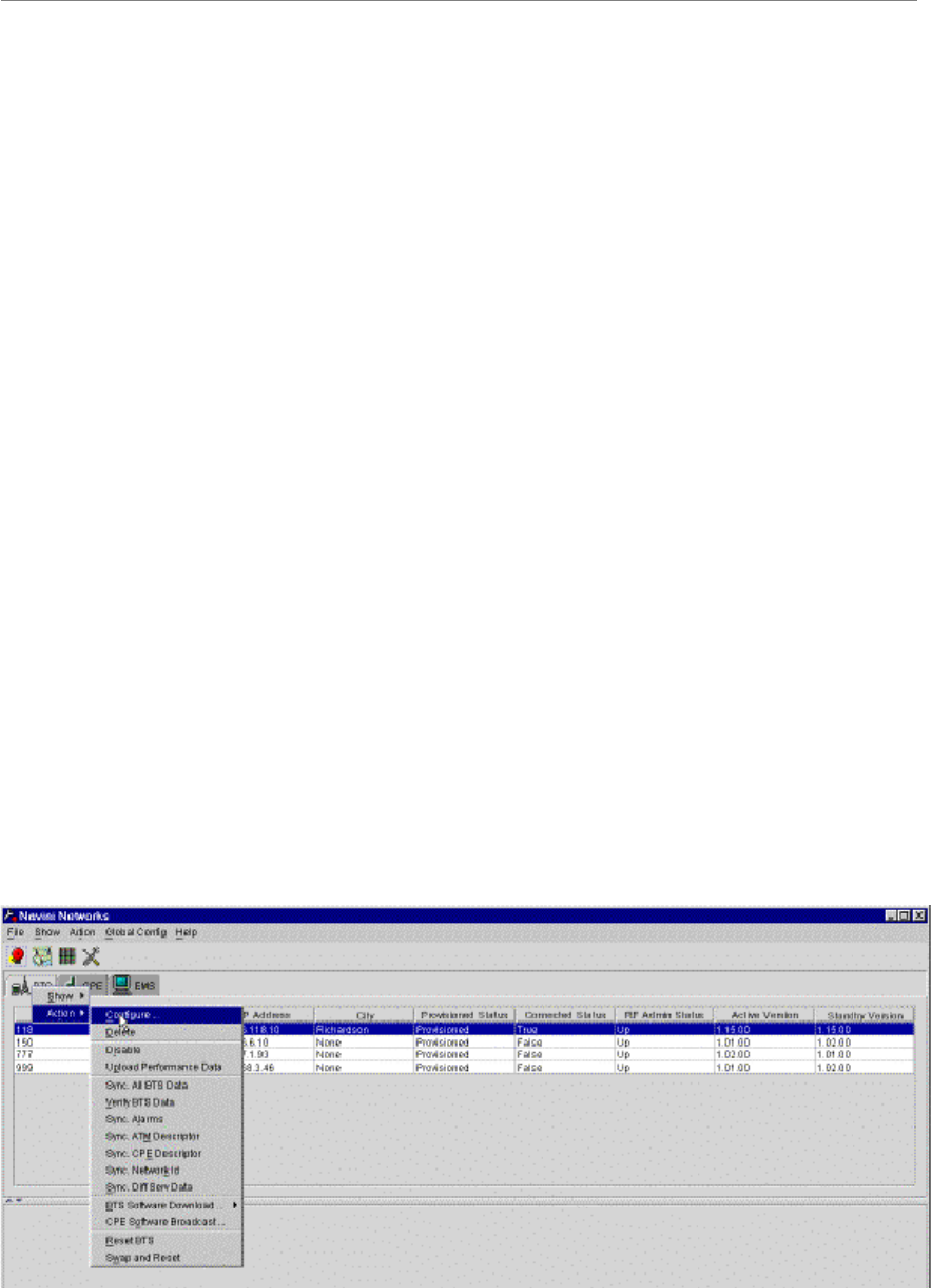
Step 5. Click on the BTS that is being installed to select it. Right-click on the highlighted BTS
and select Action > Configure. Refer to Figure 51.
Figure 51: Select BTS
Navini Networks, Inc. Ripwave Base Station I&C Guide
Chapter 3
Part #40-00047-07 Rev F v1.0 (TTA) 101
October 9, 2003
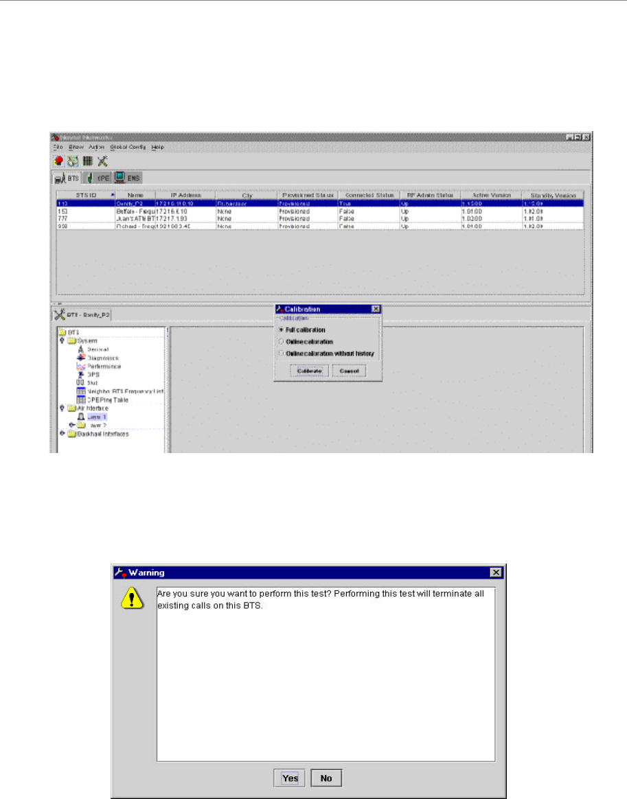
Step 6. Click on Air Interface > Layer 1, and then click Calibrate. In the resulting dialog box
(Figure 52), select FULL CALIBRATION and Calibrate.
Figure 52: Calibrate BTS
Step 7. When the Warning window appears (Figure 53), click Yes.
Figure 53: Warning Window
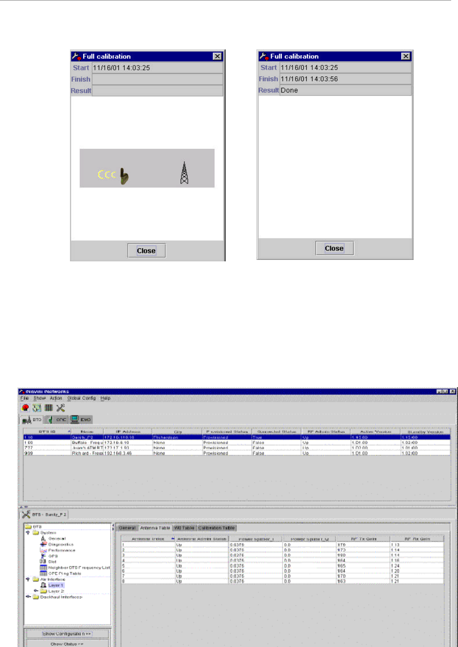
Step 8. The Full Calibration window appears during system calibration (Figure 54). When
calibration is complete, the Full Calibration window changes and displays the finish
time and the result. Click the Close button to close the Full Calibration window. Note
that the result of “Done” does not mean that the system passed calibration.
Ripwave Base Station I&C Guide Navini Networks, Inc.
Chapter 3
102 Part #40-00047-07 Rev F v1.0 (TTA)
October 9, 2003
Figure 54: Full Calibration Window
Step 9. Click Show Configuration and select the Antenna Table tab (Figure 55). Check the Tx
Gain and Rx Gain columns (the last two columns in the table) for transmit and receive
results. The transmit and receive results for all the eight antennas must be between 1
and 254. The eight values in each column should be relatively close to each other. A
value of zero indicates a problem with the associated antenna path.
Figure 55: Show Configuration/Antenna Table
Navini Networks, Inc. Ripwave Base Station I&C Guide
Chapter 3
Part #40-00047-07 Rev F v1.0 (TTA) 103
October 9, 2003
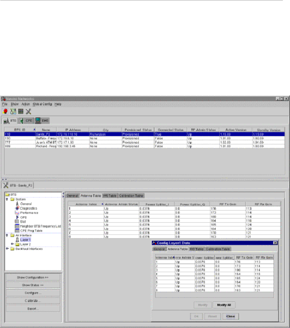
Step 10. Perform the calibration function two more times. Ensure each time that the values
remain relatively stable (+/- 3), and that none of the results is zero. After you perform
the second calibration, click on Configure. The Config Layer 1 Data window (Figure
56) shows the data from the second calibration. The values in the main screen from the
Show Config selection are from the first calibration. Compare the values from the two
calibrations to ensure that they are stable, and not equal to zero.
Figure 56: Config Layer 1 Data Window
Step 11. Close the Config Layer 1 Data window. Update the main screen by clicking the Show
Configuration button.

Ripwave Base Station I&C Guide Navini Networks, Inc.
Chapter 3
104 Part #40-00047-07 Rev F v1.0 (TTA)
October 9, 2003
Perform the Calibration Verification Procedure
Base Station Calibration Verification is a set of procedures to verify that the equipment has
passed calibration and that the RF portion of the equipment is operating within acceptable
parameters. The results of the tests should be documented in the Base Station Calibration
Verification Form, P/N 40-00059-00. This form, along with the procedure and form instructions,
may be found in Appendix V.
Single Antenna Test
The object of the RFS Single Antenna Test is to verify the functionality of each antenna element
in the Ripwave Radio Frequency Subsystem (RFS). The 8 antenna elements work together to
create the beamforming that results from using a Smart Antenna - Phased Array technology.
Using 8 combined single antenna elements creates the beamed radiation that is part of what
constitutes the gain of up to 18 dB during transmission of data. In order to verify the correct
beamforming and that each single antenna is working properly, we have to turn off the individual
PA that controls each antenna element, one at a time.
The Single Antenna Test should be performed after completing the Base Station Calibration
Verification procedure. This test is necessary since an equipment calibration does not check the
functionality of the RFS, and the Calibration Verification only searches for losses in the RFS, not
RFS functionality. More specifically, the Single Antenna Test checks the following:
1. Low Noise Amplifier (LNA) at the RFS. LNAs are an integral part of the smart antenna
technology.
2. Power Amplifiers. There is one PA for each antenna element, for a total of 8. Each PA
converts IF to RF and vice versa and amplifies the signal before transmission and after
reception.
3. Modulations. As each antenna element is checked, the variable modulations are checked.
The higher the modulation, the higher the power and the better the data rate. The test
ensures that all modulations possible, i.e., QPSK, 8PSK, and QAM16, are working
properly.
Export BTS Data
Once you complete the calibration verification, export the BTS configuration data to a text file.
This is done by highlighting the specific BTS in the Configuration and Alarms Manager (CAM)
window, and on the Main Menu select File > Export BTS Data. This saves the configuration
information if needed for later retrieval.

Navini Networks, Inc. Ripwave Base Station I&C Guide
Chapter 3
Part #40-00047-07 Rev F v1.0 (TTA) 105
October 9, 2003
Perform Local Modem Tests
Local wireline, then over-the-air, Modem testing will verify that the Base Station is working
properly and is able transmit and receive data. Data rates are not being checked at this time.
Refer to Appendix W to set up and perform the Local Modem procedures.
Install & Test Customer EMS Operations
If you have been using a Test EMS up to this point, you will now need to install and test the
customer’s EMS server. This involves installing the EMS Server and Client on a computer that is
connected through the system backhaul. When connecting the Ripwave equipment to the
backhaul, refer to the Regulatory Information in Chapter 1, Page 8 – specifically regarding
cabling to Ethernet or T1 backhauls. Ethernet connections require a UL497B listed protection
device to be installed between the BTS and the first network device. T1 connections must be
routed from the BTS through a UL497 listed protection device at the demarcation point. The
interconnect cables for T1 backhauls must be a minimum #26 AWG wire, in accordance with
NEC/CEC standards. If the customer’s EMS is already installed and has been used for testing
purposes, skip to the “Verify System Performance” section of this chapter.
Install EMS Software
The EMS software installation procedures can be found in the EMS Software Installation Guide,
P/N 40-00017-00. After installing the EMS Server and Client applications, the EMS needs to be
configured with the settings that are designated for the Base Station. The settings are found in the
Network Architecture Plan provided by the customer.
Ensure connection between the Base Station and the backhaul. The connection to the Base
Station will be either an Ethernet connection or T1 connections.
Verify EMS to Base Station Connectivity
Follow the steps below to ensure the EMS and Base Station can communicate.
Step 1. Open a Command Prompt window on the computer where the EMS is installed.
Step 2. Ping the Base Station using the CLI command ping <base station ip address>. Verify
that a reply from the Base Station is received.

Ripwave Base Station I&C Guide Navini Networks, Inc.
Chapter 3
106 Part #40-00047-07 Rev F v1.0 (TTA)
October 9, 2003
Perform Calibration Using Customer’s EMS
This step is necessary only if you have been using a Test EMS up to this point. You will need to
install the customer’s EMS server and software. Calibrate the Base Station using the customer’s
EMS. Follow the same calibration procedures described earlier in this chapter, Calibrate the Base
Station. Perform the procedure three times and make sure that the results are stable (+/–3).
Verify System Performance
Drive Study
The preliminary Drive Study is performed if no RF coverage model is available. The Drive
Study helps you to map out the coverage area. Later, the full Drive Study is performed to see if
the system’s coverage area is as predicted and, if necessary, to fine-tune the RF model.
Following the detailed Drive Study procedures in Appendix X, you will perform a preliminary
Drive Study by driving back and forth through a sector, staying on major roads about a kilometer
apart. Special attention has to be paid to the null and fringe areas. You will follow this scheme
for each sector in the site, recording the results of all tests. The test results will be sent for
evaluation, along with the Location (FTP) test results, to Navini Networks Technical Support. If
the results are not adequate, Technical Support will have you adjust some of the RF parameters
and perform the Drive Study again.
Location (FTP) Test
Location Tests are performed to see if the system file transfer functions are working as predicted
between CPE and Base Station. These are conducted in stages as well. The first stage is the
preliminary Location Test, where you perform three uploads and three downloads at three
locations with the Base Station in line-of-sight (LOS). Then you perform three uploads and three
downloads at three locations with the Base Station in non-line-of-sight (NLOS). For the NLOS
testing, you will need to find an obstacle, such as a building, between the CPE and Base Station.
Results are sent, along with the preliminary Drive Study results, to Navini Networks Technical
Support for evaluation. If the results are not adequate - i.e., file transfers do not meet customer’s
objectives - Technical Support will have you adjust some of the RF parameters and perform the
Location tests again. The detailed Location Test procedures and form are located in Appendix Y.
To summarize, these are the high-level steps for verifying system performance:
1. Conduct preliminary Drive Study (if no RF coverage map is available).
2. Conduct preliminary LOS Location Tests.
3. Conduct preliminary NLOS Location Tests.

Navini Networks, Inc. Ripwave Base Station I&C Guide
Chapter 3
Part #40-00047-07 Rev F v1.0 (TTA) 107
October 9, 2003
4. Send all test results to Navini’s Technical Support for evaluation.
5. If directed by Technical Support, adjust RF parameters.
6. Conduct full Drive Study.
7. Conduct full LOS Location Tests.
8. Conduct full NLOS Location Tests.
9. Send all test results to Navini’s Technical Support for evaluation.
The cycle continues until the performance objectives are reached.
Verify System Operation With Multiple Modems
Set up three computers with Modems connected to them. Perform file transfers from all three
computers to verify Base Station operation.
Back Up EMS Database
After all system installation and commissioning activities are complete, perform a backup of the
EMS database. The procedure can be found in the EMS Administration Guide. Place the backup
files on a different system server where they will be periodically backed up on a tape drive.
Customer Acceptance
To conclude the installation and commissioning activities, gather all of the required documents
and forms from the installation and commissioning procedures to create a comprehensive system
I&C package. Refer to Appendix Z for a summary of the documentation package. The customer
and Navini Networks will sign the Customer Acceptance Form. A copy of this form is provided
in Appendix AA. The signed form and the system I &C package are provided to the customer.
The original, signed Customer Acceptance Form and system I &C package are stored in the
Navini Networks Technical Support database.

Ripwave Base Station I&C Guide Navini Networks, Inc.
Chapter 3
108 Part #40-00047-07 Rev F v1.0 (TTA)
October 9, 2003