Cambium Networks 50450I Fixed Outdoor Point to Multipoint Transceiver User Manual 450 Platform User Guide
Cambium Networks Limited Fixed Outdoor Point to Multipoint Transceiver 450 Platform User Guide
Contents
- 1. Installation Guide
- 2. User Guide Part 1
- 3. User Guide Part 2
- 4. User Guide Part 3
- 5. User Guide Part 4
- 6. User Guide Part 5
- 7. User Guide Part 6
- 8. User Guide Part 7
- 9. Exhibit D Users Manual per 2 1033 b3
- 10. User Manual - Part 1
- 11. User Manual - Part 2
- 12. User Manual - Part 3
- 13. User Manual - Part 4
- 14. Users Manual - Part 5
- 15. Users Manual - Part 6
- 16. User Manual
User Manual - Part 2
Chapter 3: System planning Radio Frequency planning
Page 3-21
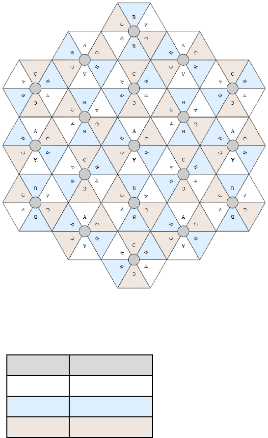
Figure 49 Example layout of 6 Access Point sectors (ABC), 60-degree sectors
An example for assignment of frequency channels and sector IDs is provided in the following
table.
Table 77 Example 5.8 GHz 3-channel assignment by access site
Symbol
Frequency
A 5.740 GHz
B 5.760 GHz
C 5.780 GHz
Chapter 3: System planning Radio Frequency planning
Page 3-22
Considerations on back-to-back frequency reuse
Cambium Networks recommends using back-to-back (ABAB) frequency reuse, as shown in Figure
48. This means that a base site of four sectors can be created using two frequencies, which works
very well and helps define networks in situations where high capacity is required in a limited
amount of spectrum.
The conditions necessary to implement this plan are:
• GPS synchronization: all the access points transmit at the same time
• Uplink and Downlink timings across APs do not overlap: they can be adjusted using the frame
calculators and co-location tools provided by Cambium
• Uplink power control to ensure that all signals are received on the uplink at the same level: this
is automatically enabled on all sectors
• There are no reflecting objects which are too large in the exclusion zones defined in this
section.
• The SMs do not normally have line-of-sight (LoS) to an interfering base station. The worst-case
range ratio in Figure 48 is 5:1 which in LoS only gives 14 dB protection. Greater than 30 dB is
required for 256QAM capability. Down tilt can be used to advantage when the elevation
beamwidth is low. Also, the range ratio applies to the longest distance SM, shorter distance
SMs have a better range ratio. This frequency reuse plan may not always give 256QAM for the
longest distance SMs. It is usually a good compromise between using more spectrum and
guaranteed modulation rate.
Reflecting objects
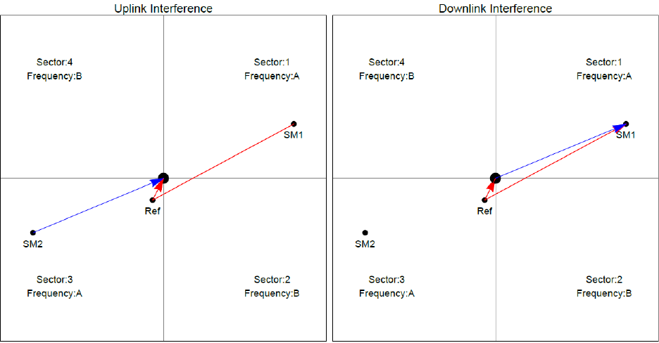
Figure 50 shows two diagrams of the same reflecting object. Uplink interference demonstrates the
situation when the two SMs are transmitting at the same time. SM2 should be received cleanly by
the AP for Sector 3. At the same time interference can arise from SM1 via the reflecting object and
cause a lower Signal-to-Interference ratio than required at AP3. This may either cause transmission
errors which are corrected by ARQ or cause the selected modulation rate to be lowered. Either
may cause a lower throughput from SM2 and therefore sector 3.
Downlink interference shows the situation when AP3 interferes with SM1. Again, the transmission
may be reduced by errors or a reduction in modulation rate.
Chapter 3: System planning Radio Frequency planning
Page 3-23
Figure 50 Reflection
Reflection likelihood guidance
As shown in the previous section, reflection can cause a decrease in throughput in an ABAB base
site. This section provides guidance on whether a reflection is likely to cause interference. The first
condition for whether a reflection can cause the data rate to reduce is that the reflecting object
must be in view of the AP and the SM to re-transmit the signal. If this is not the case, then the
object cannot cause interference.
Given that the potential reflecting object is seen by the AP and the SM, there are a range of object
sizes and a range of zones where we can predict that interference will occur which may reduce the
throughput when both sector 1 and sector 3 are carrying traffic.
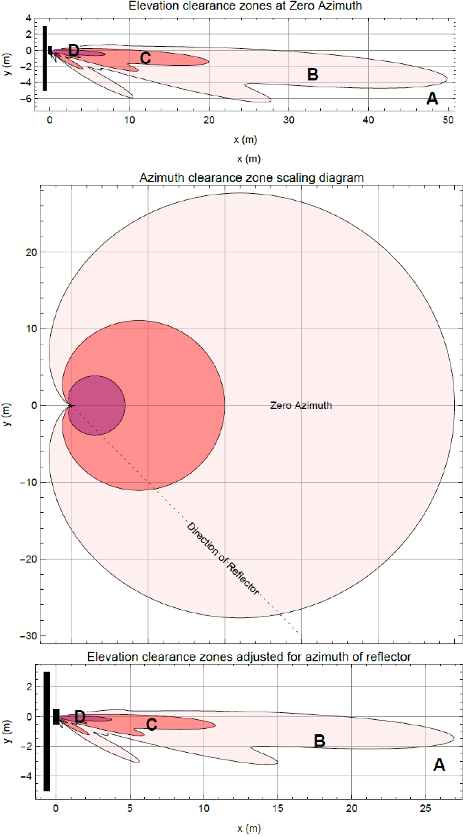
Figure 51 and Figure 52 show regions enumerated A, B, C, and D. We also need to consider objects
of size 1, 2, 3 and 4 and define the areas where the objects may interfere.
• object size 1: a flat building face with a clear reflecting property from sector to AP
• object size 2: random metalwork such as a wireless tower
• object size 3: a 0.5 X 0.5m flat metallic face or tree
• object size 4: a 0.2 X 0.2m random metal structure or 0.5 X 0.5m foliage.
The conditions for no interference are:
• size 2 outside zone B
• size 3 outside zone C
• size 4 outside zone D
The size 1 object can interfere at large distances. It is necessary to look at the geometry by which
reflection could occur and cause interference. Typically, this will occur at a restricted range of
azimuths and ranges.
Chapter 3: System planning Radio Frequency planning
Page 3-24
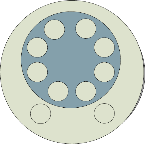
Figure 51 Sector Antenna
Chapter 3: System planning Radio Frequency planning
Page 3-25
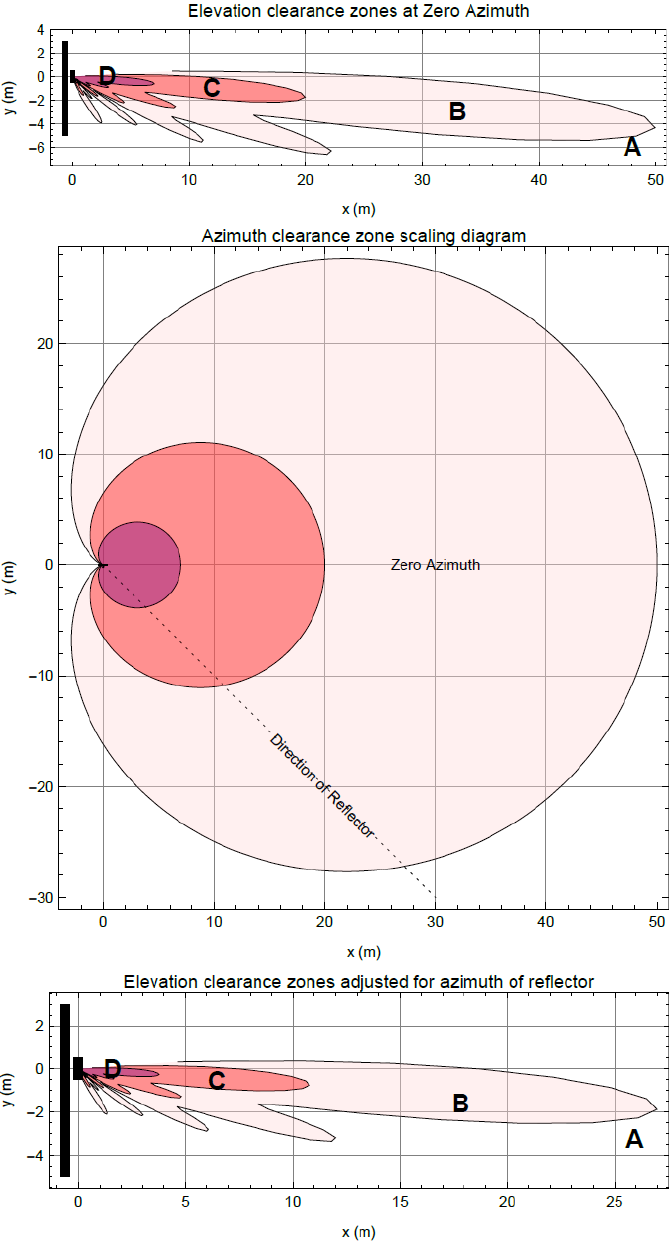
Figure 52 cnMedusa Antenna
Chapter 3: System planning Radio Frequency planning
Page 3-26
Figure 51 and Figure 52 each have three diagrams scaled in meters where Figure 51 is for the
sector antenna and Figure 52 is for cnMedusa. In each figure the distances and heights assume a
typical down tilt of 4°.
In each figure the top diagram represents the clearances required at zero azimuth. The middle
diagram represents the scaling required to the top diagram to allow for differences in azimuth of
the considered reflecting object. The bottom diagram is the scaled version of the top diagram
allowing for the dotted azimuth line in the middle diagram.
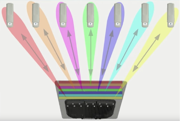
PMP 450m Series AP is based on Massive MU-MIMO technology. It is a 14x14 MIMO system which
allows simultaneous communication to up to seven SMs.
Figure 53 PMP 450m Series AP antenna beam
PMP 450m installation recommendations
• For best performance it is recommended to have a clearance zone around the mast. The
clearance zone depends on the surrounding environment and the antenna’s down tilt. If the
mast is surrounded by metal then larger clearance is required compared to an environment
where the antenna is surrounded by foliage
• SMs should be spread in azimuth of AP antenna
• 450m is susceptible to movement, for best MU-MIMO performance it is recommended that the
450m AP is mounted/installed on a mast that is extremely rigid (no movement and is 100%
vertical).
• LINKPlanner can be used to plan SMs across the AP antenna azimuth

Chapter 3: System planning Link planning
Page 3-27
Link planning
This section describes factors to be considered when planning links, such as range, obstacles path
loss and throughput. LINKPlanner is recommended.
Range and obstacles
Calculate the range of the link and identify any obstacles that may affect radio performance.
Perform a survey to identify all the obstructions (such as trees or buildings) in the path and to
assess the risk of interference. This information is necessary in order to achieve an accurate link
feasibility assessment.
The 450 Platform Family is designed to operate in Non-Line-of-Sight (NLoS) and Line-of-Sight
(LoS) environments. An NLOS environment is one in which there is no optical line-of-sight, that is,
there are obstructions between the antennas.
OFDM technology can often use multi-pathing to an advantage to overcome nLOS, especially in
cases where the Fresnel zone is only partially blocked by buildings, “urban canyons”, or foliage.
OFDM tends to help especially when obstacles are near the middle of the link, and less so when
the obstacles are very near the ODU.
However, attenuation through walls and trees is substantial for any use of the 5.4 GHz and 5.8 GHz
frequency bands. The lower frequency radio waves of 900 MHz radios provide greater penetration
through walls, trees and other obstacles, making it optimal for most non-line-of-sight applications.
Even with OFDM, these products are not expected to penetrate walls or extensive trees and
foliage.
Path loss
Path loss is the amount of attenuation the radio signal undergoes between the two ends of the
link. The path loss is the sum of the attenuation of the path if there were no obstacles in the way
(Free Space Path Loss), the attenuation caused by obstacles (Excess Path Loss) and a margin to
allow for possible fading of the radio signal (Fade Margin). The following calculation needs to be
performed to judge whether a link can be installed:
capabilityseasonalfadeexcessspace
free
LLLLL <+
++
_
Where: Is:
spacefree
L_
Free Space Path Loss (dB)
excess
L
Excess Path Loss (dB)
fade
L
Fade Margin Required (dB)
Chapter 3: System planning Link planning
Page 3-28
seasonal
L
Seasonal Fading (dB)
capability
L
Equipment Capability (dB)
Calculating Link Loss
The link loss is the total attenuation of the wireless signal between two point-to-multipoint units.
The link loss calculation is presented below:
Link Loss (dB) = Transmit power of the remote wireless unit (dBm) − Tx Cable loss (dB)
− Received power at the local unit (dBm) – Rx cable loss (dB) +
Antenna gain at the remote unit (dBi) + Antenna gain at the local unit
(dBi)
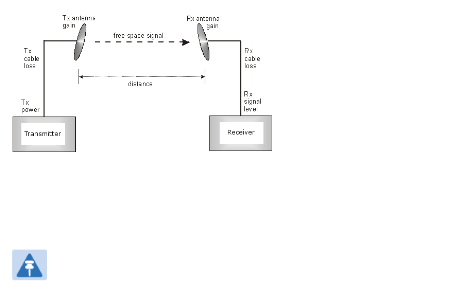
Calculating Rx Signal Level
The determinants in Rx signal level are illustrated in Figure 54.
Figure 54 Determinants in Rx signal level
Rx signal level is calculated as follows:
Rx signal level dB = Tx power − Tx cable loss + Tx antenna gain
− free space path loss + Rx antenna gain − Rx cable loss
Note
This Rx signal level calculation presumes that a clear line of sight is established
between the transmitter and receiver and that no objects encroach in the Fresnel zone.
Chapter 3: System planning Link planning
Page 3-29
Calculating Fade Margin
Free space path loss is a major determinant in Rx (received) signal level. Rx signal level, in turn, is
a major factor in the system operating margin (fade margin), which is calculated as follows:
System operating margin (fade margin) dB = Rx signal level dB − Rx sensitivity dB
Thus, fade margin is the difference between strength of the received signal and the strength that
the receiver requires for maintaining a reliable link. A higher fade margin is characteristic of a
more reliable link.
Adaptive modulation
Adaptive modulation ensures that the highest throughput that can be achieved instantaneously
will be obtained, taking account of propagation and interference. When the link has been installed,
web pages provide information about the link loss currently measured by the equipment, both
instantaneously and averaged. The averaged value will require maximum seasonal fading to be
added, and then the radio reliability of the link can be computed.
For details of the system throughput, link loss and maximum distance for each frequency band in
all modulation modes, see Link on page 10-45.

Chapter 3: System planning Planning for connectorized units
Page 3-30
Planning for connectorized units
This section describes factors to be considered when planning to use connectorized ODUs with
external antennas in 450 Platform Family links.
When to install connectorized units
Most of radio links can be successfully deployed with the integrated ODU. However, the integrated
units may not be sufficient in some areas, for example:
• Where the path is heavily obscured by dense woodland on an NLOS link.
• Where long LOS links are required.
• Where there are known to be high levels of interference.
In these areas, connectorized ODUs and external antennas should be used.
Choosing external antennas
When selecting external antennas, consider the following factors:
• The required antenna gain.
• Ease of mounting and alignment.
• Use dual-polarization antenna (as the integrated antenna).
Note
Enter the antenna gain and cable loss into the Installation Wizard, if the country
selected has an EIRP limit, the corresponding maximum transmit power will be
calculated automatically by the unit.
Calculating RF cable length (5.8 GHz FCC only)
The 5.8 GHz band FCC approval for the product is based on tests with a cable loss between the
ODU and antenna of not less than 1.2 dB. If cable loss is below 1.2 dB with a 1.3 m (4 ft) diameter
external antenna, the connectorized 450 Platform Family may exceed the maximum radiated
spurious emissions allowed under FCC 5.8 GHz rules.
Cable loss depends mainly upon cable type and length. To meet or exceed the minimum loss of
1.2 dB, use cables of the type and length specified in Table 78 (source: Times Microwave). This
data excludes connector losses.

Chapter 3: System planning Planning for connectorized units
Page 3-31
Table 78 RF cable lengths required to achieve 1.2 dB loss at 5.8 GHz
RF cable type
Minimum cable length
LMR100 0.6 m (1.9 ft)
LMR200 1.4 m (4.6 ft)
LMR300 2.2 m (7.3 ft)
LMR400 3.4 m (11.1 ft)
LMR600 5.0 m (16.5 ft)

Chapter 3: System planning Data network planning
Page 3-32
Data network planning
This section describes factors to be considered when planning 450 Platform Family data networks.
Understanding addresses
A basic understanding of Internet Protocol (IP) address and subnet mask concepts is required for
engineering your IP network.
IP address
The IP address is a 32-bit binary number that has four parts (octets). This set of four octets has two
segments, depending on the class of IP address. The first segment identifies the network. The
second identifies the hosts or devices on the network. The subnet mask marks a boundary
between these two sub-addresses.
Dynamic or static addressing
For any computer to communicate with a module, the computer must be configured to either
• use DHCP (Dynamic Host Configuration Protocol). In this case, when not connected to the
network, the computer derives an IP address on the 169.254 network within two minutes.
• have an assigned static IP address (for example, 169.254.1.5) on the 169.254 network.
Note
If an IP address that is set in the module is not the 169.254.x.x network address, then
the network operator must assign the computer a static IP address in the same subnet.
When a DHCP server is not found
To operate on a network, a computer requires an IP address, a subnet mask, and possibly a
gateway address. Either a DHCP server automatically assigns this configuration information to a
computer on a network or an operator must input these items.
When a computer is brought on line and a DHCP server is not accessible (such as when the server
is down or the computer is not plugged into the network), Microsoft and Apple operating systems
default to an IP address of 169.254.x.x and a subnet mask of 255.255.0.0 (169.254/16, where /16
indicates that the first 16 bits of the address range are identical among all members of the subnet).
Chapter 3: System planning Data network planning
Page 3-33
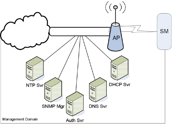
DNS Client
The DNS Client is used to resolve names of management servers within the operator’s
management domain (see Figure 55). This feature allows hostname configuration for NTP servers,
Authorization Servers, DHCP relay servers, and SNMP trap servers. Operators may choose to
either enter in the FQDN (Fully Qualified Domain Name) for the host name or to manually enter the
IP addresses of the servers.
Figure 55 Cambium networks management domain
Network Address Translation (NAT)
NAT, DHCP Server, DHCP Client and DMZ in SM
The system provides NAT (network address translation) for SMs in the following combinations of
NAT and DHCP (Dynamic Host Configuration Protocol):
• NAT Disabled
• NAT with DHCP Client (DHCP selected as the Connection Type of the WAN interface) and DHCP
Server
• NAT with DHCP Client (DHCP selected as the Connection Type of the WAN interface)
• NAT with DHCP Server
• NAT without DHCP
NAT
NAT isolates devices connected to the Ethernet/wired side of a SM from being seen directly from
the wireless side of the SM. With NAT enabled, the SM has an IP address for transport traffic
(separate from its address for management), terminates transport traffic, and allows you to assign
a range of IP addresses to devices that are connected to the Ethernet/wired side of the SM.
Chapter 3: System planning Data network planning
Page 3-34
In the Cambium system, NAT supports many protocols, including HTTP, ICMP (Internet Control
Message Protocols), and FTP (File Transfer Protocol). For virtual private network (VPN)
implementation, L2TP over IPSec (Level 2 Tunneling Protocol over IP Security) and PPTP (Point to
Point Tunneling Protocol) are supported.
DHCP
DHCP enables a device to be assigned a new IP address and TCP/IP parameters, including a default
gateway, whenever the device reboots. Thus DHCP reduces configuration time, conserves IP
addresses, and allows modules to be moved to a different network within the Cambium system.
In conjunction with the NAT features, each SM provides:
• A DHCP server that assigns IP addresses to computers connected to the SM by Ethernet
protocol.
• A DHCP client that receives an IP address for the SM from a network DHCP server.
DMZ
In conjunction with the NAT features, a DMZ (demilitarized zone) allows the assignment of one IP
address behind the SM for a device to logically exist outside the firewall and receive network
traffic. The first three octets of this IP address must be identical to the first three octets of the NAT
private IP address.
Developing an IP addressing scheme
Network elements are accessed through IP Version 4 (IPv4) addressing.
A proper IP addressing method is critical to the operation and security of a network.
Each module requires an IP address on the network. This IP address is for only management
purposes. For security, you must either:
• Assign a non-routable IP address.
• Assign a routable IP address only if a firewall is present to protect the module.
You assign an IP addresses to computers and network components by either static or dynamic IP
addressing. You will also assign the appropriate subnet mask and network gateway to each
module.
Address Resolution Protocol
As previously stated, the MAC address identifies a module in:
• Communications between modules.
• The data that modules store about each other.
Chapter 3: System planning Data network planning
Page 3-35
The IP address is essential for data delivery through a router interface. Address Resolution
Protocol (ARP) correlates MAC addresses to IP addresses.
For communications to outside the network segment, ARP reads the network gateway address of
the router and translates it into the MAC address of the router. Then the communication is sent to
MAC address (physical network interface card) of the router.
For each router between the sending module and the destination, this sequence applies. The ARP
correlation is stored until the ARP cache times out.
Allocating subnets
The subnet mask is a 32-bit binary number that filters the IP address. Where a subnet mask
contains a bit set to 1, the corresponding bit in the IP address is part of the network address.
Example IP address and subnet mask
In Figure 56, the first 16 bits of the 32-bit IP address identify the network:
Figure 56 Example of IP address in Class B subnet
Octet 1
Octet 2
Octet 3
Octet 4
IP address 169.254.1.1 10101001 11111110 00000001 00000001
Subnet mask 255.255.0.0 11111111 11111111 00000000 00000000
In this example, the network address is 169.254 and 216 (65,536) hosts are addressable.
Selecting non-routable IP addresses
The factory default assignments for network elements are:
• Unique MAC address
• IP address of 169.254.1.1
• Subnet mask of 255.255.0.0
• Network gateway address of 169.254.0.0
For each radio and CMM4, assign an IP address that is both consistent with the IP addressing plan
for your network and cannot be accessed from the Internet. IP addresses within the following
ranges are not routable from the Internet, regardless of whether a firewall is configured:
• 10.0.0.0 – 10.255.255.255
• 172.16.0.0 – 172.31.255.255
• 192.168.0.0 – 192.168.255.255
Also, the subnet mask and network gateway for each CMM4 can be assigned.
Chapter 3: System planning Data network planning
Page 3-36
Translation bridging
Optionally, the AP can be configured to change the source MAC address in every packet it receives
from its SMs to the MAC address of the SM/BHS that bridged the packet, before forwarding the
packet toward the public network. In this case:
• Not more than 128 IP devices at any time are valid to send data to the AP from behind the SM.
• SM populates the Translation Table tab of its Statistics web page, displaying the MAC address
and IP address of all the valid connected devices.
• Each entry in the Translation Table is associated with the number of minutes that have elapsed
since the last packet transfer between the connected device and the SM.
• If 128 are connected, and another attempt to connect:
o If no Translation Table entry is older than 255 minutes, the attempt is ignored.
o If an entry is older than 255 minutes, the oldest entry is removed and the attempt is
successful.
• The Send Untranslated ARP parameter in the General tab of the Configuration page can be:
o Disabled, so that the AP overwrites the MAC address in ARP packets before forwarding
them.
o Enabled, so that the AP forwards ARP packets regardless of whether it has overwritten the
MAC address.
This is the Translation Bridging feature, which you can enable in the General page of the
Configuration web page in the AP. When this feature is disabled, the setting of the
Send Untranslated ARP parameter has no effect, because all packets are forwarded untranslated
(with the source MAC address intact). See Address Resolution Protocol on Page 3-34.
Engineering VLANs
The radios support VLAN functionality as defined in the 802.1Q (Virtual LANs) specification, except
for the following aspects of that specification:
• Protocols:
o Generic Attribute Registration Protocol (GARP) GARV
o Spanning Tree Protocol (STP)
o Multiple Spanning Tree Protocol (MSTP)
o GARP Multicast Registration Protocol (GMRP)
• Embedded source routing (ERIF) in the 802.1Q header
• Multicast pruning
• Flooding unknown unicast frames in the downlink
As an additional exception, the AP/BHM does not flood downward the unknown unicast frames to
the SM/BHS.
A VLAN configuration in Layer 2 establishes a logical group within the network. Each computer in
the VLAN, regardless of initial or eventual physical location, has access to the same data. For the
network operator, this provides flexibility in network segmentation, simpler management, and
enhanced security.

Chapter 3: System planning Data network planning
Page 3-37
Special case VLAN numbers
This system handles special case VLAN numbers according to IEEE specifications:
Table 79 Special case VLAN IDs
VLAN Number
Purpose
Usage Constraint
0 These packets have 802.1p priority, but are
otherwise handled as untagged.
Must not be used as a
management VLAN.
1
Although not noted as special case by IEEE
specifications, these packets identify traffic
that was untagged upon ingress into the SM
and must remain untagged upon egress.
This policy is hard-coded in the AP.
Must not be used for
system VLAN traffic.
4095 This VLAN is reserved for internal use. Must not be used at all.
SM membership in VLANs
With the supported VLAN functionality, the radios determine bridge forwarding on the basis of not
only the destination MAC address, but also the VLAN ID of the destination. This provides flexibility
in how SMs are used:
• Each SM can be a member in its own VLAN.
• Each SM can be in its own broadcast domain, such that only the radios that are members of
the VLAN can see broadcast and multicast traffic to and from the SM.
• The network operator can define a work group of SMs, regardless of the AP(s) to which they
register.

Chapter 3: System planning Data network planning
Page 3-38
PMP 450 Platform Family modules provide the VLAN frame filters that are described in Table 80.
Table 80 VLAN filters in point-to-multipoint modules
Where VLAN is active,
if this parameter value
is selected …
then a frame is discarded if…
because of this VLAN
filter in the software:
entering the bridge/
NAT switch through…
Ethernet…
TCP/IP…
any combination of
VLAN
parameter settings
with a VID not in the
membership table Ingress
any combination of
VLAN
parameter settings
with a VID not in
the
membership table
Local Ingress
Allow Frame Types:
Tagged Frames Only
with no 802.1Q tag Only Tagged
Allow Frame Types:
Untagged Frames Only
with an 802.1Q tag,
regardless of VID Only Untagged
Local SM Management:
Disable
in the SM, or
All Local SM
Management:
Disable
in the AP
with an 802.1Q tag
and a VID in the
membership table
Local SM Management
leaving the bridge/
NAT switch through…
Ethernet…
TCP/IP…
any combination of
VLAN
parameter settings
with a VID not in the
membership table Egress
any combination of
VLAN
parameter settings
with a VID not in
the
membership table
Local Egress
Priority on VLANs (802.1p)
The radios can prioritize traffic based on the eight priorities described in the IEEE 802.1p
specification. When the high-priority channel is enabled on a SM, regardless of whether VLAN is
enabled on the AP for the sector, packets received with a priority of 4 through 7 in the 802.1p field
are forwarded onto the high-priority channel.

Chapter 3: System planning Data network planning
Page 3-39
Operators may configure priority precedence as 802.1p Then Diffserv (Default) or Diffserv Then
802.1p. Since these priority precedence configurations are independent between the AP and SM,
this setting must be configured on both the AP and SM to ensure that the precedence is adhered to
by both sides of the link.
VLAN settings can also cause the module to convert received non-VLAN packets into VLAN
packets. In this case, the 802.1p priority in packets leaving the module is set to the priority
established by the DiffServ configuration.
If VLAN is enabled, immediately monitor traffic to ensure that the results are as desired. For
example, high-priority traffic may block low-priority.
Q-in-Q DVLAN (Double-VLAN) Tagging (802.1ad)
PMP and PTP modules can be configured with 802.1ad Q-in-Q DVLAN (Double-VLAN) tagging
which is a way for an operator to put an 802.1Q VLAN inside of an 802.1ad VLAN. A nested VLAN,
which is the original 802.1Q tag and a new second 802.1ad tag, allows for bridging of VLAN traffic
across a network and segregates the broadcast domains of 802.1Q VLANs. Q-in-Q can be used
with PPPoE and/or NAT.
The 802.1ad standard defines the S-VLAN as the Service Provider VLAN and the C-VLAN as the
customer VLAN. The radio software does 2-layer Q-in-Q whereby the C-VLAN is the 802.1Q tag and
the S-VLAN is the second layer Q tag as shown in Table 81.
Table 81 Q-in-Q Ethernet frame
Ethernet Header S-VLAN EthType
0x88a8
C-VLAN EthType
0x8100 IP Data EthType 0x0800
The 802.1ad S-VLAN is the outer VLAN that is configurable on the Configuration > VLAN web page
of the AP/BHM. The Q-in-Q EtherType parameter is configured with a default EtherType of 0x88a8
in addition to four alternate EtherTypes that can be configured to aid in interoperability with
existing networks that use a different EtherType than the default.
The C-VLAN is the inner VLAN tag, which is the same as 802.1Q. As a top-level concept, this
operates on the outermost tag at any given time, either “pushing” a tag on or “popping” a tag off.
This means packets will at most transition from an 802.1Q frame to an 801.ad frame (with a tag
“pushed” on) or an untagged 802.1 frame (with the tag “popped” off. Similarly, for an 802.1ad
frame, this can only transition from an 802.1ad frame to an 802.1Q frame (with the tag “popped”
off) since the radio software only supports 2 levels of tags.

Chapter 3: System planning Network management planning
Page 3-40
Network management planning
This section describes how to plan for 450 Platform Family links to be managed remotely using
SNMP.
Planning for SNMP operation
Cambium modules provide the following SNMP traps for automatic notifications to the NMS:
• coldStart, which signals that the SNMPv2c element is reinitializing itself and that its
configuration may have been altered.
• warmStart, which signals that the SNMPv2c element is reinitializing such that its configuration
is unaltered.
• authenticationFailure, which signals that the SNMPv2c element has received a protocol
message that is not properly authenticated (contingent on the snmpEnableAuthenTraps object
setting).
• linkDown, as defined in RFC 1573
• linkUp, as defined in RFC 1573
• egpNeighborLoss, as defined in RFC 1213
• whispGPSInSync, which signals a transition from not synchronized to synchronized.
• whispGPSOutSync, which signals a transition from synchronized to not synchronized.
• whispRegComplete, which signals registration completed.
• whispRegLost, which signals registration lost.
• whispRadarDetected, which signals that the one-minute scan has been completed, radar has
been detected and the radio will shut down.
• whispRadarEnd, which signals that the one-minute scan has been completed, radar has not
been detected and the radio will resume normal operation.
Note
The proprietary MIBs are provided in the 450 Platform Family software download files
in the support website (see Contacting Cambium Networks on page 1).
Enabling SNMP
Enable the SNMP interface for use by configuring the following attributes in the SNMP
Configuration page:
• SNMP State (default disabled)
• SNMP Version (default SNMPv2c)
• SNMP Port Number (default 161)

Chapter 3: System planning Security planning
Page 3-41
Security planning
This section describes how to plan for 450 Platform Family links to operate in secure mode.
• Managing module access by passwords
• Filtering protocols and ports
• Port Configuration
Isolating AP/BHM from the Internet
Ensure that the IP addresses of the AP/BHM in the network:
• are not routable over the Internet.
• do not share the subnet of the IP address of your user.
RFC 1918, Address Allocation for Private Subnets, reserves for private IP networks three blocks of
IP addresses that are not routable over the Internet:
• /8 subnets have one reserved network, 10.0.0.0 to 10.255.255.255.
• /16 subnets have 16 reserved networks, 172.16.0.0 to 172.31.255.255.
• /24 subnets have 256 reserved networks, 192.168.0.0 to 192.168.255.255.
Encrypting radio transmissions
Cambium fixed wireless broadband IP systems employ the following form of encryption for
security of the wireless link:
• DES (Data Encryption Standard): An over-the-air link encryption option that uses secret 56-bit
keys and 8 parity bits. DES performs a series of bit permutations, substitutions, and
recombination operations on blocks of data. DES encryption does not affect the performance
or throughput of the system.
• AES (Advanced Encryption Standard): An over-the-air link encryption option that uses the
Rijndael algorithm and 128-bit keys to establish a higher level of security than DES. AES
products are certified as compliant with the Federal Information Processing Standards (FIPS
197) in the U.S.A.
The default encryption setting for 450 Platform Family ODU is "None".

Chapter 3: System planning Security planning
Page 3-42
Planning for HTTPS operation
Before starting to configure HTTPS operation, ensure that the cryptographic material listed in
Table 82 is available.
Table 82 HTTPS security material
Item
Description
Quantity required
User Defined Security
Banner
The banner provides warnings and notices
to be read by the user before logging in to
the ODU. Use text that is appropriate to
the network security policy.
Normally one per link.
This depends upon
network policy.
Port numbers for HTTP,
HTTPS and Telnet
Port numbers allocated by the network. As allocated by
network.
Planning for SNMPv3 operation
SNMP security mode
Decide how SNMPv3 security will be configured.
MIB-based security management uses standard SNMPv3 MIBs to configure the user-based
security model and the view-based access control model. This approach provides considerable
flexibility, allowing a network operator to tailor views and security levels appropriate for different
types of user. MIB-based security management may allow a network operator to take advantage of
built-in security management capabilities of existing network managers.
Web-based security management allows an operator to configure users, security levels, privacy
and authentication protocols, and passphrases using the 450 Platform Family web-based
management interface. The capabilities supported are somewhat less flexible than those
supported using the MIB-based security management, but will be sufficient in many applications.
Selection of web-based management for SNMPv3 security disables the MIB-based security
management. 450 Platform Family does not support concurrent use of MIB-based and web-based
management of SNMPv3 security.
Web-based management of SNMPv3 security
Initial configuration of SNMPv3 security is available only to HTTP or HTTPS user accounts with
security role of Security Officer.
Identify the format used for SNMP Engine ID. The following formats are available:
• MAC address (default)
• 5 and 32 hex characters (the hex character input is driven by RFC 3411 recommendations on
the Engine ID)

Chapter 3: System planning Security planning
Page 3-43
Identify the user names and security roles of initial SNMPv3 users. Two security roles are
available:
• Read Only
• System Administrator
Identify the security level for each of the security roles. Three security levels are available:
(a) No authentication, no privacy
(b) Authentication, no privacy
(c) Authentication, privacy
If authentication is required, identify the protocol. The authentication protocol available is MD5.
If privacy will be used, identify the protocol. The privacy protocol available is cbc-des.
Managing module access by passwords
From the factory, each module has a preconfigured administrator-level account in the name root,
which initially requires no associated password. When you upgrade a module:
• An account is created in the name admin.
• Both admin and root inherit the password that was previously used to access the module, if:
o Full Access password, if one was set.
o Display-Only Access password, if one was set and no Full Access password was set.
Caution
If you use Wireless Manager, do not delete the root account from any module. If you
use a NMS that communicates with modules through SNMP, do not delete the root
account from any module unless you first can confirm that the NMS does not rely on
the root account for access to the modules.
Each module supports four or fewer user accounts, regardless of account levels. The available
levels are
• ADMINISTRATOR, who has full read and write permissions. This is the level of the root and
admin users, as well as any other administrator accounts that one of them creates.
• INSTALLER, who has permissions identical to those of ADMINISTRATOR except that the
installer cannot add or delete users or change the password of any other user.
• TECHNICIAN, who has permissions to modify basic radio parameters and view informational
web pages.
• GUEST, who has no write permissions and only a limited view of General Status tab.
• Admin, Installer and Tech accounts can be configured as READ-ONLY. This will allow the
account to only see the items.
The ability to view information of General Status tab can be controlled by the "Site Information
Viewable to Guest Users" under the SNMP tab.
Chapter 3: System planning Security planning
Page 3-44
From the factory default state, configure passwords for both the root and admin account at the
ADMINISTRATOR permission level, using the Account > Change Users Password page. (If
configure only one of these, then the other will still require no password for access into it and thus
remain a security risk.) If you are intent on configuring only one of them, delete the admin account.
The root account is the only account that CNUT uses to update the module.
After a password has been set for any ADMINISTRATOR-level account, initial access to the module
GUI opens the view of GUEST level.
Planning for RADIUS operation
Configure RADIUS where remote authentication is required for users of the web-based interface.
Remote authentication has the following advantages:
• Control of passwords can be centralized.
• Management of user accounts can be more sophisticated. For example; users can be prompted
by a network manager to change passwords at regular intervals. As another example,
passwords can be checked for inclusion of dictionary words and phrases.
• Passwords can be updated without reconfiguring multiple network elements.
• User accounts can be disabled without reconfiguring multiple network elements.
Remote authentication has one significant disadvantage in a wireless link product such as 450
Platform Family. If the wireless link is down, a unit on the remote side of the broken link may be
prevented from contacting a RADIUS Server, with the result that users are unable to access the
web-based interface.
One useful strategy would be to combine RADIUS authentication for normal operation with a
single locally-authenticated user account for emergency use.
PMP 450 Platform Family SM provides a choice of the following authentication methods:
• Phase 1:
o EAP-MSCHAPv2
o EAP-TTLS
o EAP PEAP
• Phase 2:
o PAP
o CHAP
o MSCHAPv2
Ensure that the authentication method selected in 450 Platform Family is supported by the RADIUS
server.
Filtering protocols and ports
Configure filters for specified protocols and ports from leaving the AP/BHM and SM/BHS and
entering the network. This protects the network from both intended and inadvertent packet loading
or probing by network users. By keeping the specified protocols or ports off the network, this
feature also provides a level of protection to users from each other.

Chapter 3: System planning Security planning
Page 3-45
Protocol and port filtering is set per AP/SM/BH. Except for filtering of SNMP ports, filtering occurs
as packets leave the AP/SM/BH.
For example, if SM is configured to filter SNMP, then SNMP packets are blocked from entering the
SM and, thereby, from interacting with the SNMP portion of the protocol stack on the SM.
Port Filtering with NAT Enabled
Where NAT is enabled on the SM/BHS, the filtering can be enabled for only the user-defined ports.
The following are examples for situations where the configure port can be filtered where NAT is
enabled:
• To block a subscriber from using FTP, you can filter Ports 20 and 21 (the FTP ports) for both the
TCP and UDP protocols.
• To block a subscriber from access to SNMP, you can filter Ports 161 and 162 (the SNMP ports)
for both the TCP and UDP protocols.
Note
In only the SNMP case, filtering occurs before the packet interacts with the protocol
stack.
Protocol and Port Filtering with NAT Disabled
Where NAT is disabled on the SM/BHS, the filtering can be enabled for both protocols and the
three user-defined ports. Using the check boxes on the interface, it can be either:
• Allow all protocols except those that user wish to block.
• Block all protocols except those that user wish to allow.
Allow or block any of the following protocols:
• PPPoE (Point to Point Protocol over Ethernet)
• Any or all the following IPv4 (Internet Protocol version 4) protocols:
o SMB (Network Neighborhood)
o SNMP
o Bootp Client
o Bootp Server
o Up to 3 user-defined ports
o All other IPv4 traffic (see Figure 29)
• Any or all of the following IPv6 (Internet Protocol version 6) protocols:
o SMB (Network Neighborhood)
o SNMP
o Bootp Client
o Bootp Server
o Up to 3 user-defined ports
Chapter 3: System planning Security planning
Page 3-46
o All other IPv6 traffic (see Figure 29)
• Filter Direction – Upstream and Downstream
• ARP (Address Resolution Protocol)
Figure 57 Categorical protocol filtering
The following are example situations in which the protocol filtering is configured where NAT is
disabled:
• If a subscriber is blocked from only PPPoE and SNMP, then the subscriber retains access to all
other protocols and all ports.
• If PPPoE, IPv4, and Uplink Broadcast are blocked, and check the All others selection, then only
Address Resolution Protocol is not filtered.
The ports filtered because of protocol selections in the Protocol Filtering tab of the SM/BHS are
listed in Table 83.
BootP
Client
BootP
Server
SNMP
IPv4
Multica
st
User
Defined
Port 1
SMB
User
Defined
Port 3
User
Defined
Port 2
PPPoE ARP
All
Others
All
Other
IPv4

Chapter 3: System planning Security planning
Page 3-47
Table 83 Ports filtered per protocol selections
Port Configuration
450 Platform Family supports access to various communication protocols and only the ports
required for these protocols are available for access by external entities. Operators may change
the port numbers for these protocols via the radio GUI or SNMP.
Table 84 Device default port numbers
Port
Usage
Port Usage
Device
21 FTP Listen Port AP, SM
80 HTTP Listen Port AP, SM
443 HTTPS Listen Port AP, SM
161 SNMP port Listen Port AP, SM
162 SNMP trap port Destination Port AP, SM
514 Syslog Server port Destination Port AP, SM
1812 Standard RADIUS port Destination Port AP
1813 Standard RADIUS accounting port Destination Port AP, SM
Protocol Selected
Port Filtered (Blocked)
SMB Destination Ports UDP: 137, 138, 139, 445, 3702 and 1900
Destination Ports TCP: 137, 138, 139, 445, 2869, 5357 and 5358
SNMP Destination Ports TCP and UDP: 161 and 162
Bootp Client Source Port 68 UDP
Bootp Server Source Port 67 UDP
User Defined Port 1..3 User defined ports for filtering UDP and TCP
IPv4 Multicast Block IPv4 packet types except other filters defined
IPv6 Multicast Block IPv6 packet types except other filters defined
ARP Filter all Ethernet packet type 806
Upstream Applies packet filtering to traffic coming into the FEC interface
Downstream Applies packet filtering to traffic destined to exit the FEC
interface
Chapter 3: System planning Security planning
Page 3-48
Encrypting downlink broadcasts
An AP can be enabled to encrypt downlink broadcast packets such as the following:
• ARP
• NetBIOS
• broadcast packets containing video data on UDP.
The encryption used is DES for a DES-configured module and AES for an AES-configured module.
Before the Encrypt Downlink Broadcast feature is enabled on the AP, air link security must be
enabled on the AP.
Isolating SMs in PMP
In an AP, SMs in the sector can be prevented from directly communicating with each other. In
CMM4, the connected APs can be prevented from directly communicating with each other, which
prevents SMs that are in different sectors of a cluster from communicating with each other.
In the AP, the SM Isolation parameter is available in the General tab of the Configuration web
page. Configure the SM Isolation feature by any of the following selections from drop-down menu:
• Disable SM Isolation (the default selection). This allows full communication between SMs.
• Enable Option 1 - Block SM destined packets from being forwarded. This prevents both
multicast/broadcast and unicast SM-to-SM communication.
• Enable Option 2 - Forward SM destined packets upstream. This not only prevents
multicast/broadcast and unicast SM-to-SM communication but also sends the packets, which
otherwise may have been handled SM to SM, through the Ethernet port of the AP.
In the CMM and the CMM4, SM isolation treatment is the result of how to manage the port-based
VLAN feature of the embedded switch, where all traffic can be switched from any AP to a specified
uplink port. However, this is not packet level switching. It is not based on VLAN IDs.
Filtering management through Ethernet
Configure the SM to disallow any device that is connected to its Ethernet port from accessing the
IP address of the SM. If the Ethernet Access Control parameter is set to Enabled, then:
• No attempt to access the SM management interface (by http, SNMP, ftp, or tftp) through
Ethernet is granted.
• Any attempt to access the SM management interface over the air (by IP address, presuming
that LAN1 Network Interface Configuration, Network Accessibility is set to Public, or by link
from the Session Status or Remote Subscribers tab in the AP) is unaffected.
Chapter 3: System planning Security planning
Page 3-49
Allowing management from only specified IP addresses
The Security sub-menu of the Configuration web page in the AP/BHM and SM/BHS includes the IP
Access Control parameter. Specify one, two, or three IP addresses that must be allowed to access
the management interface (by HTTP, SNMP, FTP or TFTP).
If the selection is:
• IP Access Filtering Disabled, then management access is allowed from any IP address, even if
the Allowed Source IP 1 to 3 parameters are populated.
• IP Access Filtering Enabled, and specify at least one address in the Allowed Source IP 1 to 3
parameter, then management access is limited to the specified address(es).
Configuring management IP by DHCP
The Configuration > IP web page of every radio contains a LAN1 Network Interface Configuration,
DHCP State parameter that, if enabled, causes the IP configuration (IP address, subnet mask, and
gateway IP address) to be obtained through DHCP instead of the values of those individual
parameters. The setting of this DHCP state parameter is also viewable, but is not settable, in the
Network Interface tab of the Home page.
In the SM/BHS, this parameter is settable
• in the NAT tab of the Configuration web page, but only if NAT is enabled.
• in the IP tab of the Configuration web page, but only if the Network Accessibility parameter in
the IP tab is set to Public.
DHCP option 81
The DHCP server can be used to register and update the pointer (PTR) and host (A) DNS resource
records on behalf of its DHCP-enabled clients.
The DHCP option 81 permits the client to provide its fully qualified domain name (FQDN) as well as
instructions to the DHCP server on how it would like the server to process DNS dynamic updates
(if any) on its behalf. The hostname is populated as SiteName.DomainName depending upon
following conditions:
• If Sitename is default i.e. No Site Name, mac address will be used instead.
• The SiteName should only be a-z | A-Z | 0-9 and period(.) and dash (-).
• The domain name part should not start or end with dash (-).
• The underscore or space in domain name part will be converted to dash (-), anything else apart
from valid characters will be skipped.
Chapter 3: System planning Security planning
Page 3-50
Controlling PPPoE PADI Downlink Forwarding
The AP supports the control of forwarding of PPPoE PADI (PPPoE Active Discovery Initiation)
packets. This forwarding is configured on the AP GUI Configuration > Radio page by parameter
PPPoE PADI Downlink Forwarding. When set to “Enabled”, the AP allows downstream and
upstream transmission of PPPoE PADI packets. When set to “Disabled”, the AP does NOT allow
PPPoE PADI packets to be sent out of the AP RF interface (downstream) but will allow PPPoE PADI
packets to enter the RF interface (upstream) and exit the Ethernet interface.
Chapter 3: System planning Remote AP Deployment
Page 3-51
Remote AP Deployment
In cases where the subscriber population is widely distributed, or conditions such as geography
restrict network deployment, you can add a Remote AP to:
• provide high-throughput service to near LoS business subscribers.
• reach around obstructions or penetrate foliage with non-LoS throughput.
• reach new, especially widely distributed, residential subscribers with broadband service.
• pass sync to an additional RF hop.
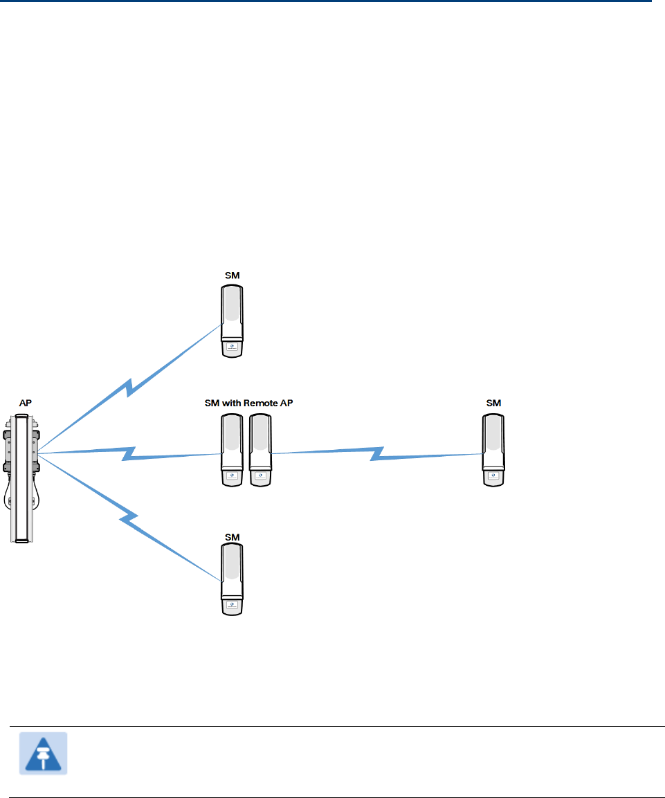
In the remote AP configuration, a remote AP is co-located with an SM. The remote AP distributes
the signal to SMs that are logically behind the co-located SM. A remote AP deployment is
illustrated in Figure 58.
Figure 58 Remote AP deployment
The co-located SM receives data in one channel, and the remote AP must redistribute the data in a
different channel. The two channels need to have a frequency gap equal to at least two times the
used channel bandwidth.
Base your selection of frequency band ranges on regulatory restrictions, environmental conditions,
and throughput requirements.
Note
Each relay hop (additional daisy-chained remote AP) adds approximately 5-7 msec
round trip latency.
Chapter 3: System planning Remote AP Deployment
Page 3-52
Remote AP (RAP) Performance
The performance of a remote AP is identical to the AP performance in cluster. Throughputs,
ranges, and antenna coverage are identical.
As with all equipment operating in the unlicensed spectrum, Cambium strongly recommends that
you perform site surveys before you add network elements. These will indicate that spectrum is
available in the area where you want to grow. Keep in mind that:
• non-LoS ranges heavily depend on environmental conditions.
• in most regions, not all frequencies are available.
• your deployments must be consistent with local regulatory restrictions.
Example Use Case for RF Obstructions
A remote AP can be used to provide last-mile access to a community where RF obstructions
prevent SMs from communicating with the higher-level AP in cluster. For example, you may be
able to use 900 MHz for the last mile between a remote AP and the outlying SMs where these
subscribers cannot form good links to a higher-level 5 GHz AP. In this case, the ability of the 900-
MHz wavelength to be effective around foliage at short range solves the foliage penetration
problem.
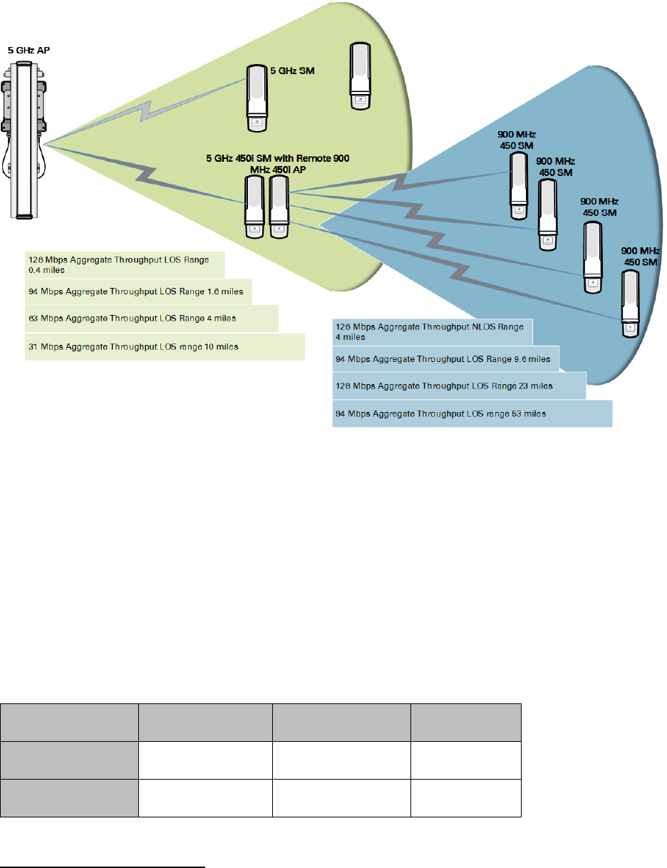
An example of this use case is shown in Figure 59.
In this example, the 5 GHz AP is a PMP 450i AP in the 5.8 GHz band operating on a 20 MHz channel
with a 2.5 ms frame; the SMs are 5 GHz PMP 450 integrated SMs. The SM connected to the remote
AP is a PMP 450i SM.
The remote AP is a PMP 450i AP in the 900 MHz band, also operating in a 20 MHz channel with a
2.5 ms frame; the SMs are 900 MHz PMP 450 connectorized SMs using the Cambium 23 dBi gain
antenna.
Chapter 3: System planning Remote AP Deployment
Page 3-53
Figure 59 Example for 900-MHz remote AP behind 5 GHz SM
The 5 GHz modules provide a sustained aggregate throughput of up to 126 Mbps to the sector.
One of the SMs in the sector is wired to a 900-MHz remote AP, which provides NLoS sustained
aggregate throughput2 of:
• 126 Mbps to 900-MHz SMs up to 4 miles away in the sector.
• 94 Mbps to 900-MHz SMs between 4 and 10 miles away in the sector.
Example Use Case for Passing Sync
All radios support the remote AP functionality. The BHS and the SM can reliably pass the sync
pulse, and the BHM and AP can reliably receive it.
However, not all devices are compatible with all other devices. The following table shows which
SMs can be connected to which APs.
Devices
PMP 450 AP/BHM PMP 450i AP/BHM PMP 450m AP
PMP 450 SM/BHS X
PMP 450i SM/BHS X X
2 NLoS ranges depend on environmental conditions. Your results may vary from these.
Chapter 3: System planning Remote AP Deployment
Page 3-54
Examples of passing sync over cable are shown under Passing Sync in an Additional Hop on page
3-56.
For PMP 450, the sync is passed in a cable that connects Pins 1 and 6 of the RJ-11 timing ports of
the two modules.
For PMP 450i/450m the sync is passed in a cable that connects Pins7 and 8 of the RJ-45 timing
ports of the two modules.
When connecting modules in this way, make sure the AP and SM are properly configured, as
described in the Wiring to Extend Network Sync.
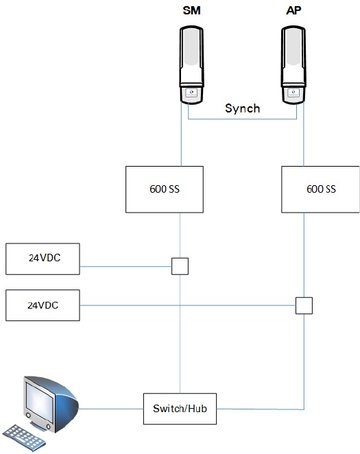
Physical Connections Involving the Remote AP
The SM to which a remote AP is connected to can be either an SM that serves a customer or an
SM that simply serves as a relay. If the SM serves a customer, wire the remote AP to the SM as
shown in Figure 60.
Figure 60 Remote AP wired to SM that also serves a customer
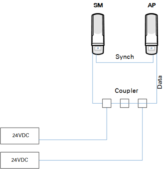
If the SM simply serves as a relay, you must use a straight-through RJ-45 female-to-female coupler
and wire the SM to the remote AP as shown in Figure 61.
Chapter 3: System planning Remote AP Deployment
Page 3-55
Figure 61 Remote AP wired to SM that serves as a relay
Chapter 3: System planning Remote AP Deployment
Page 3-56
Passing Sync signal
Passing Sync in a Single Hop
Network sync can be passed in a single hop in the following network designs:
• Design 1
o A CMM provides sync to a co-located AP.
o This AP sends the sync over the air to SMs.
• Design 2
o A CMM provides sync to a co-located BH timing master.
o This BH timing master sends the sync over the air to a BH timing slave.
Passing Sync in an Additional Hop
Network sync can be extended by one additional link in any of the following network designs:
Note
In each of these following designs, Link 2 is not on the same frequency band as Link 4.
(For example, Link 2 may be a 5.2 GHz link while Link 4 is a 5.7 or 2.4 GHz link.)
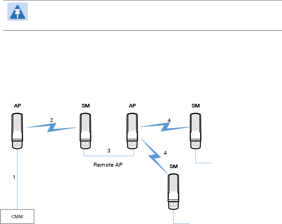
• Design 3
o A CMM provides sync to a co-located AP.
o This AP sends the sync over the air to an SM.
o This SM delivers the sync to a co-located AP.
o This AP passes the sync in the additional link over the air to SMs.
This design is illustrated in Figure 62.
Figure 62 Additional link to extend network sync, Design 3
Chapter 3: System planning Remote AP Deployment
Page 3-57
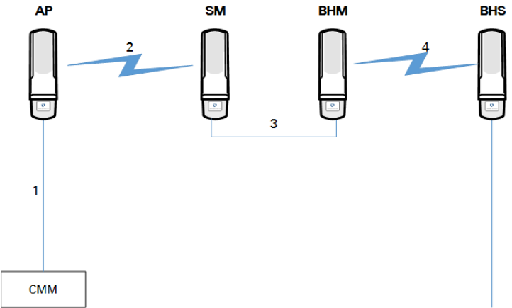
• Design 4
o A CMM provides sync to a co-located AP.
o This AP sends the sync over the air to an SM.
o This SM delivers the sync to a co-located BHM.
o This BHM passes the sync in the additional link over the air to a BHS.
This design is illustrated in Figure 63.
Figure 63 Additional link to extend network sync, Design 4
Chapter 3: System planning Remote AP Deployment
Page 3-58
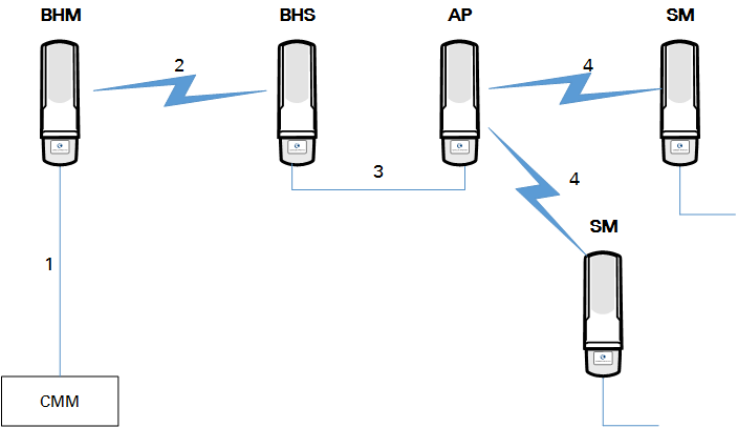
• Design 5
o A CMM provides sync to a co-located BHM or the BHM generates timing.
o This BHM sends the sync over the air to a BHS.
o This BHS delivers the sync to a co-located AP.
This AP passes the sync in the additional link over the air to SMs.
This design is illustrated in Figure 64.
Figure 64 Additional link to extend network sync, Design 5
Wiring and configuration information for this sync extension is described under Wiring to Extend
Network Sync on page 3-59.
Chapter 3: System planning Remote AP Deployment
Page 3-59
Wiring to Extend Network Sync
The following procedure can be used to extend network sync by one additional hop, as described
under Passing Sync in an Additional Hop on page 3-56. When a co-located module receives sync
over the air, the co-located modules can be wired to pass the sync as follows:
1. Connect the GPS Utility ports of the co-located modules using a sync cable with RJ-11 (for
450) or RJ-45 (for 450i/450m) connectors.
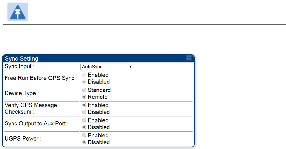
2. Set the Sync Input parameter on the Configuration page of the co-located AP or BH timing
master to AutoSync.
3. Set the Device Type parameter on the Configuration page of the co-located AP or BH
timing master to Remote.
4. Set the Sync Output to Aux Port parameter on the Configuration page of the co-located AP
or BH timing master to Disabled.
5. Set the UGPS Power parameter on the Configuration page of the co-located AP or BH
timing master to Disabled.
6. Set the Frame Timing Pulse Gated parameter on the Configuration page of the co-located
SM or BH timing slave to Enable.
Note
This setting prevents interference if the SM or BH timing slave loses sync.
Figure 65 Co-located AP or BH timing master Sync Setting configuration

Page 4-1
Chapter 4: Legal and regulatory information
This chapter provides end user license agreements and regulatory notifications.
Caution
Intentional or unintentional changes or modifications to the equipment must not be
made unless under the express consent of the party responsible for compliance. Any
such modifications could void the user’s authority to operate the equipment and will
void the manufacturer’s warranty.
Attention
Changements ou modifications Intentionnels ou non de l'équipement ne doivent pas
être entrepris sans l'autorisation de l’organisme responsable de la déclaration de
conformité. Ces modifications ou changements pourraient invalider le droit de
l'utilisateur à utiliser cet appareil et annuleraient la garantie du fabricant.
The following topics are described in this chapter:
• Cambium Networks end user license agreement on page 4-2 contains the Cambium and third-
party license agreements for the 450 Platform Family ODUs.
• Compliance with safety standards on page 4-22 lists the safety specifications against which the
450 Platform Family has been tested and certified. It also describes how to keep RF exposure
within safe limits.
• Compliance with radio regulations on page 4-33 describes how the 450 Platform Family
complies with the radio regulations that are in force in various countries, and contains
notifications made to regulatory bodies for the 450 Platform Family.

Chapter 4: Legal and regulatory information Cambium Networks end user license agreement
Page 4-2
Cambium Networks end user license agreement
Definitions
In this Agreement, the word “Software” refers to the set of instructions for computers, in
executable form and in any media, (which may include diskette, CD-ROM, downloadable internet,
hardware, or firmware) licensed to you. The word “Documentation” refers to electronic or printed
manuals and accompanying instructional aids licensed to you. The word “Product” refers to
Cambium Networks’ fixed wireless broadband devices for which the Software and Documentation
is licensed for use.
Acceptance of this agreement
In connection with Cambium Networks’ delivery of certain proprietary software or products
containing embedded or pre-loaded proprietary software, or both, Cambium Networks is willing to
license this certain proprietary software and the accompanying documentation to you only on the
condition that you accept all the terms in this End User License Agreement (“Agreement”).
IF YOU DO NOT AGREE TO THE TERMS OF THIS AGREEMENT, DO NOT USE THE PRODUCT OR
INSTALL THE SOFTWARE. INSTEAD, YOU MAY, FOR A FULL REFUND, RETURN THIS PRODUCT
TO THE LOCATION WHERE YOU ACQUIRED IT OR PROVIDE WRITTEN VERIFICATION OF
DELETION OF ALL COPIES OF THE SOFTWARE. ANY USE OF THE SOFTWARE, INCLUDING BUT
NOT LIMITED TO USE ON THE PRODUCT, WILL CONSTITUTE YOUR ACCEPTANCE TO THE
TERMS OF THIS AGREEMENT.
Grant of license
Cambium Networks Limited (“Cambium”) grants you (“Licensee” or “you”) a personal,
nonexclusive, non-transferable license to use the Software and Documentation subject to the
Conditions of Use set forth in “Conditions of use” and the terms and conditions of this Agreement.
Any terms or conditions relating to the Software and Documentation appearing on the face or
reverse side of any purchase order, purchase order acknowledgment or other order document that
are different from, or in addition to, the terms of this Agreement will not be binding on the parties,
even if payment is accepted.
Chapter 4: Legal and regulatory information Cambium Networks end user license agreement
Page 4-3
Conditions of use
Any use of the Software and Documentation outside of the conditions set forth in this Agreement
is strictly prohibited and will be deemed a breach of this Agreement.
1. Only you, your employees or agents may use the Software and Documentation. You will take all
necessary steps to insure that your employees and agents abide by the terms of this Agreement.
2. You will use the Software and Documentation (i) only for your internal business purposes; (ii)
only as described in the Software and Documentation; and (iii) in strict accordance with this
Agreement.
3. You may use the Software and Documentation, provided that the use is in conformance with the
terms set forth in this Agreement.
4. Portions of the Software and Documentation are protected by United States copyright laws,
international treaty provisions, and other applicable laws. Therefore, you must treat the Software
like any other copyrighted material (for example, a book or musical recording) except that you may
either: (i) make 1 copy of the transportable part of the Software (which typically is supplied on
diskette, CD-ROM, or downloadable internet), solely for back-up purposes; or (ii) copy the
transportable part of the Software to a PC hard disk, provided you keep the original solely for back-
up purposes. If the Documentation is in printed form, it may not be copied. If the Documentation
is in electronic form, you may print out 1 copy, which then may not be copied. With regard to the
copy made for backup or archival purposes, you agree to reproduce any Cambium Networks
copyright notice, and other proprietary legends appearing thereon. Such copyright notice(s) may
appear in any of several forms, including machine-readable form, and you agree to reproduce
such notice in each form in which it appears, to the extent it is physically possible to do so.
Unauthorized duplication of the Software or Documentation constitutes copyright infringement,
and in the United States is punishable in federal court by fine and imprisonment.
5. You will not transfer, directly or indirectly, any product, technical data or software to any
country for which the United States Government requires an export license or other governmental
approval without first obtaining such license or approval.
Chapter 4: Legal and regulatory information Cambium Networks end user license agreement
Page 4-4
Title and restrictions
If you transfer possession of any copy of the Software and Documentation to another party outside
of the terms of this agreement, your license is automatically terminated. Title and copyrights to the
Software and Documentation and any copies made by you remain with Cambium Networks and its
licensors. You will not, and will not permit others to: (i) modify, translate, decompile, bootleg,
reverse engineer, disassemble, or extract the inner workings of the Software or Documentation,
(ii) copy the look-and-feel or functionality of the Software or Documentation; (iii) remove any
proprietary notices, marks, labels, or logos from the Software or Documentation; (iv) rent or
transfer all or some of the Software or Documentation to any other party without Cambium’s prior
written consent; or (v) utilize any computer software or hardware which is designed to defeat any
copy protection device, should the Software and Documentation be equipped with such a
protection device. If the Software and Documentation is provided on multiple types of media (such
as diskette, CD-ROM, downloadable internet), then you will only use the medium which best meets
your specific needs, and will not loan, rent, lease, or transfer the other media contained in the
package without Cambium’s written consent. Unauthorized copying of the Software or
Documentation, or failure to comply with any of the provisions of this Agreement, will result in
automatic termination of this license.
Confidentiality
You acknowledge that all Software and Documentation contain valuable proprietary information
and trade secrets and that unauthorized or improper use of the Software and Documentation will
result in irreparable harm to Cambium Networks for which monetary damages would be
inadequate and for which Cambium Networks will be entitled to immediate injunctive relief. If
applicable, you will limit access to the Software and Documentation to those of your employees
and agents who need to use the Software and Documentation for your internal business purposes,
and you will take appropriate action with those employees and agents to preserve the
confidentiality of the Software and Documentation, using the same degree of care to avoid
unauthorized or improper disclosure as you use for the protection of your own proprietary
software, but in no event less than reasonable care.
You have no obligation to preserve the confidentiality of any proprietary information that: (i) was
in the public domain at the time of disclosure; (ii) entered the public domain through no fault of
yours; (iii) was given to you free of any obligation to keep it confidential; (iv) is independently
developed by you; or (v) is disclosed as required by law provided that you notify Cambium
Networks prior to such disclosure and provide Cambium Networks with a reasonable opportunity
to respond.
Chapter 4: Legal and regulatory information Cambium Networks end user license agreement
Page 4-5
Right to use Cambium’s name
Except as required in “Conditions of use”, you will not, during the term of this Agreement or
thereafter, use any trademark of Cambium Networks, or any word or symbol likely to be confused
with any Cambium Networks trademark, either alone or in any combination with another word or
words.
Transfer
The Software and Documentation may not be transferred to another party without the express
written consent of Cambium Networks, regardless of whether or not such transfer is accomplished
by physical or electronic means. Cambium’s consent may be withheld at its discretion and may be
conditioned upon transferee paying all applicable license fees and agreeing to be bound by this
Agreement.
Updates
During the first 12 months after purchase of a Product, or during the term of any executed
Maintenance and Support Agreement for the Product, you are entitled to receive Updates. An
“Update” means any code in any form which is a bug fix, patch, error correction, or minor
enhancement, but excludes any major feature added to the Software. Updates are available for
download at the support website.
Major features may be available from time to time for an additional license fee. If Cambium
Networks makes available to your major features and no other end user license agreement is
provided, then the terms of this Agreement will apply.
Maintenance
Except as provided above, Cambium Networks is not responsible for maintenance or field service
of the Software under this Agreement.
Chapter 4: Legal and regulatory information Cambium Networks end user license agreement
Page 4-6
Disclaimer
CAMBIUM NETWORKS DISCLAIMS ALL WARRANTIES OF ANY KIND, WHETHER EXPRESS,
IMPLIED, STATUTORY, OR IN ANY COMMUNICATION WITH YOU. CAMBIUM NETWORKS
SPECIFICALLY DISCLAIMS ANY WARRANTY INCLUDING THE IMPLIED WARRANTIES OF
MERCHANTABILTY, NONINFRINGEMENT, OR FITNESS FOR A PARTICULAR PURPOSE. THE
SOFTWARE AND DOCUMENTATION ARE PROVIDED “AS IS.” CAMBIUM NETWORKS DOES NOT
WARRANT THAT THE SOFTWARE WILL MEET YOUR REQUIREMENTS, OR THAT THE OPERATION
OF THE SOFTWARE WILL BE UNINTERRUPTED OR ERROR FREE, OR THAT DEFECTS IN THE
SOFTWARE WILL BE CORRECTED. CAMBIUM NETWORKS MAKES NO WARRANTY WITH
RESPECT TO THE CORRECTNESS, ACCURACY, OR RELIABILITY OF THE SOFTWARE AND
DOCUMENTATION. Some jurisdictions do not allow the exclusion of implied warranties, so the
above exclusion may not apply to you.
Limitation of liability
IN NO EVENT SHALL CAMBIUM NETWORKS BE LIABLE TO YOU OR ANY OTHER PARTY FOR ANY
DIRECT, INDIRECT, GENERAL, SPECIAL, INCIDENTAL, CONSEQUENTIAL, EXEMPLARY OR OTHER
DAMAGE ARISING OUT OF THE USE OR INABILITY TO USE THE PRODUCT (INCLUDING,
WITHOUT LIMITATION, DAMAGES FOR LOSS OF BUSINESS PROFITS, BUSINESS
INTERRUPTION, LOSS OF BUSINESS INFORMATION OR ANY OTHER PECUNIARY LOSS, OR
FROM ANY BREACH OF WARRANTY, EVEN IF CAMBIUM NETWORKS HAS BEEN ADVISED OF
THE POSSIBILITY OF SUCH DAMAGES. (Some states do not allow the exclusion or limitation of
incidental or consequential damages, so the above exclusion or limitation may not apply to you.)
IN NO CASE SHALL CAMBIUM’S LIABILITY EXCEED THE AMOUNT YOU PAID FOR THE PRODUCT.
U.S. government
If you are acquiring the Product on behalf of any unit or agency of the U.S. Government, the
following applies. Use, duplication, or disclosure of the Software and Documentation is subject to
the restrictions set forth in subparagraphs (c) (1) and (2) of the Commercial Computer Software –
Restricted Rights clause at FAR 52.227-19 (JUNE 1987), if applicable, unless being provided to the
Department of Defense. If being provided to the Department of Defense, use, duplication, or
disclosure of the Products is subject to the restricted rights set forth in subparagraph (c) (1) (ii) of
the Rights in Technical Data and Computer Software clause at DFARS 252.227-7013 (OCT 1988), if
applicable. Software and Documentation may or may not include a Restricted Rights notice, or
other notice referring specifically to the terms and conditions of this Agreement. The terms and
conditions of this Agreement will each continue to apply, but only to the extent that such terms
and conditions are not inconsistent with the rights provided to you under the aforementioned
provisions of the FAR and DFARS, as applicable to the particular procuring agency and
procurement transaction.
Chapter 4: Legal and regulatory information Cambium Networks end user license agreement
Page 4-7
Term of license
Your right to use the Software will continue in perpetuity unless terminated as follows. Your right
to use the Software will terminate immediately without notice upon a breach of this Agreement by
you. Within 30 days after termination of this Agreement, you will certify to Cambium Networks in
writing that through your best efforts, and to the best of your knowledge, the original and all
copies, in whole or in part, in any form, of the Software and all related material and
Documentation, have been destroyed, except that, with prior written consent from Cambium
Networks, you may retain one copy for archival or backup purposes. You may not sublicense,
assign or transfer the license or the Product, except as expressly provided in this Agreement. Any
attempt to otherwise sublicense, assign or transfer any of the rights, duties or obligations
hereunder is null and void.
Governing law
This Agreement is governed by the laws of the United States of America to the extent that they
apply and otherwise by the laws of the State of Illinois.
Assignment
This agreement may not be assigned by you without Cambium’s prior written consent.
Survival of provisions
The parties agree that where the context of any provision indicates an intent that it survives the
term of this Agreement, then it will survive.
Entire agreement
This agreement contains the parties’ entire agreement regarding your use of the Software and
may be amended only in writing signed by both parties, except that Cambium Networks may
modify this Agreement as necessary to comply with applicable laws.
Third party software
The software may contain one or more items of Third-Party Software supplied by other third-party
suppliers. The terms of this Agreement govern your use of any Third-Party Software UNLESS A
SEPARATE THIRD-PARTY SOFTWARE LICENSE IS INCLUDED, IN WHICH CASE YOUR USE OF THE
THIRD-PARTY SOFTWARE WILL THEN BE GOVERNED BY THE SEPARATE THIRD-PARTY LICENSE.
Chapter 4: Legal and regulatory information Cambium Networks end user license agreement
Page 4-8
Net SNMP
Various copyrights apply to this package, listed in various separate parts below. Please make sure
that you read all the parts.
---- Part 1: CMU/UCD copyright notice: (BSD like) -----
Copyright 1989, 1991, 1992 by Carnegie Mellon University
Derivative Work - 1996, 1998-2000
Copyright 1996, 1998-2000 The Regents of the University of California
All Rights Reserved
Permission to use, copy, modify and distribute this software and its documentation for any
purpose and without fee is hereby granted, provided that the above copyright notice appears in all
copies and that both that copyright notice and this permission notice appear in supporting
documentation, and that the name of CMU and The Regents of the University of California not be
used in advertising or publicity pertaining to distribution of the software without specific written
permission.
CMU AND THE REGENTS OF THE UNIVERSITY OF CALIFORNIA DISCLAIM ALL WARRANTIES
WITH REGARD TO THIS SOFTWARE, INCLUDING ALL IMPLIED WARRANTIES OF
MERCHANTABILITY AND FITNESS. IN NO EVENT SHALL CMU OR THE REGENTS OF THE
UNIVERSITY OF CALIFORNIA BE LIABLE FOR ANY SPECIAL, INDIRECT OR CONSEQUENTIAL
DAMAGES OR ANY DAMAGES WHATSOEVER RESULTING FROM THE LOSS OF USE, DATA OR
PROFITS, WHETHER IN AN ACTION OF CONTRACT, NEGLIGENCE OR OTHER TORTIOUS ACTION,
ARISING OUT OF OR IN CONNECTION WITH THE USE OR PERFORMANCE OF THIS SOFTWARE.
---- Part 2: Networks Associates Technology, Inc copyright notice (BSD) -----
Copyright © 2001-2003, Networks Associates Technology, Inc
All rights reserved.
Redistribution and use in source and binary forms, with or without modification, are permitted
provided that the following conditions are met:
• Redistributions of source code must retain the above copyright notice, this list of conditions
and the following disclaimer.
• Redistributions in binary form must reproduce the above copyright notice, this list of
conditions and the following disclaimer in the documentation and/or other materials provided
with the distribution.
• Neither the name of the Networks Associates Technology, Inc nor the names of its contributors
may be used to endorse or promote products derived from this software without specific prior
written permission.
Chapter 4: Legal and regulatory information Cambium Networks end user license agreement
Page 4-9
THIS SOFTWARE IS PROVIDED BY THE COPYRIGHT HOLDERS AND CONTRIBUTORS “AS IS”
AND ANY EXPRESS OR IMPLIED WARRANTIES, INCLUDING, BUT NOT LIMITED TO, THE IMPLIED
WARRANTIES OF MERCHANTABILITY AND FITNESS FOR A PARTICULAR PURPOSE ARE
DISCLAIMED. IN NO EVENT SHALL THE COPYRIGHT HOLDERS OR CONTRIBUTORS BE LIABLE
FOR ANY DIRECT, INDIRECT, INCIDENTAL, SPECIAL, EXEMPLARY, OR CONSEQUENTIAL
DAMAGES (INCLUDING, BUT NOT LIMITED TO, PROCUREMENT OF SUBSTITUTE GOODS OR
SERVICES; LOSS OF USE, DATA, OR PROFITS; OR BUSINESS INTERRUPTION) HOWEVER
CAUSED AND ON ANY THEORY OF LIABILITY, WHETHER IN CONTRACT, STRICT LIABILITY, OR
TORT (INCLUDING NEGLIGENCE OR OTHERWISE) ARISING IN ANY WAY OUT OF THE USE OF
THIS SOFTWARE, EVEN IF ADVISED OF THE POSSIBILITY OF SUCH DAMAGE.
---- Part 3: Cambridge Broadband Ltd. copyright notice (BSD) -----
Portions of this code are copyright © 2001-2003, Cambridge Broadband Ltd.
All rights reserved.
Redistribution and use in source and binary forms, with or without modification, are permitted
provided that the following conditions are met:
• Redistributions of source code must retain the above copyright notice, this list of conditions
and the following disclaimer.
• Redistributions in binary form must reproduce the above copyright notice, this list of
conditions and the following disclaimer in the documentation and/or other materials provided
with the distribution.
• The name of Cambridge Broadband Ltd. may not be used to endorse or promote products
derived from this software without specific prior written permission.
THIS SOFTWARE IS PROVIDED BY THE COPYRIGHT HOLDER “AS IS” AND ANY EXPRESS OR
IMPLIED WARRANTIES, INCLUDING, BUT NOT LIMITED TO, THE IMPLIED WARRANTIES OF
MERCHANTABILITY AND FITNESS FOR A PARTICULAR PURPOSE ARE DISCLAIMED. IN NO
EVENT SHALL THE COPYRIGHT HOLDER BE LIABLE FOR ANY DIRECT, INDIRECT, INCIDENTAL,
SPECIAL, EXEMPLARY, OR CONSEQUENTIAL DAMAGES (INCLUDING, BUT NOT LIMITED TO,
PROCUREMENT OF SUBSTITUTE GOODS OR SERVICES; LOSS OF USE, DATA, OR PROFITS; OR
BUSINESS INTERRUPTION) HOWEVER CAUSED AND ON ANY THEORY OF LIABILITY, WHETHER
IN CONTRACT, STRICT LIABILITY, OR TORT (INCLUDING NEGLIGENCE OR OTHERWISE) ARISING
IN ANY WAY OUT OF THE USE OF THIS SOFTWARE, EVEN IF ADVISED OF THE POSSIBILITY OF
SUCH DAMAGE.
---- Part 4: Sun Microsystems, Inc. copyright notice (BSD) -----
Copyright © 2003 Sun Microsystems, Inc., 4150 Network Circle, Santa Clara,
California 95054, U.S.A. All rights reserved.
Use is subject to license terms below.
This distribution may include materials developed by third parties.
Sun, Sun Microsystems, the Sun logo and Solaris are trademarks or registered trademarks of Sun
Microsystems, Inc. in the U.S. and other countries.
Redistribution and use in source and binary forms, with or without modification, are permitted
provided that the following conditions are met:
Chapter 4: Legal and regulatory information Cambium Networks end user license agreement
Page 4-10
• Redistributions of source code must retain the above copyright notice, this list of conditions
and the following disclaimer.
• Redistributions in binary form must reproduce the above copyright notice, this list of
conditions and the following disclaimer in the documentation and/or other materials provided
with the distribution.
• Neither the name of the Sun Microsystems, Inc. nor the names of its contributors may be used
to endorse or promote products derived from this software without specific prior written
permission.
THIS SOFTWARE IS PROVIDED BY THE COPYRIGHT HOLDERS AND CONTRIBUTORS “AS IS”
AND ANY EXPRESS OR IMPLIED WARRANTIES, INCLUDING, BUT NOT LIMITED TO, THE IMPLIED
WARRANTIES OF MERCHANTABILITY AND FITNESS FOR A PARTICULAR PURPOSE ARE
DISCLAIMED. IN NO EVENT SHALL THE COPYRIGHT HOLDERS OR CONTRIBUTORS BE LIABLE
FOR ANY DIRECT, INDIRECT, INCIDENTAL, SPECIAL, EXEMPLARY, OR CONSEQUENTIAL
DAMAGES (INCLUDING, BUT NOT LIMITED TO, PROCUREMENT OF SUBSTITUTE GOODS OR
SERVICES; LOSS OF USE, DATA, OR PROFITS; OR BUSINESS INTERRUPTION) HOWEVER
CAUSED AND ON ANY THEORY OF LIABILITY, WHETHER IN CONTRACT, STRICT LIABILITY, OR
TORT (INCLUDING NEGLIGENCE OR OTHERWISE) ARISING IN ANY WAY OUT OF THE USE OF
THIS SOFTWARE, EVEN IF ADVISED OF THE POSSIBILITY OF SUCH DAMAGE.
---- Part 5: Sparta, Inc copyright notice (BSD) -----
Copyright © 2003-2008, Sparta, Inc
All rights reserved.
Redistribution and use in source and binary forms, with or without modification, are permitted
provided that the following conditions are met:
• Redistributions of source code must retain the above copyright notice, this list of conditions
and the following disclaimer.
• Redistributions in binary form must reproduce the above copyright notice, this list of
conditions and the following disclaimer in the documentation and/or other materials provided
with the distribution.
• Neither the name of Sparta, Inc nor the names of its contributors may be used to endorse or
promote products derived from this software without specific prior written permission.
THIS SOFTWARE IS PROVIDED BY THE COPYRIGHT HOLDERS AND CONTRIBUTORS “AS IS”
AND ANY EXPRESS OR IMPLIED WARRANTIES, INCLUDING, BUT NOT LIMITED TO, THE IMPLIED
WARRANTIES OF MERCHANTABILITY AND FITNESS FOR A PARTICULAR PURPOSE ARE
DISCLAIMED. IN NO EVENT SHALL THE COPYRIGHT HOLDERS OR CONTRIBUTORS BE LIABLE
FOR ANY DIRECT, INDIRECT, INCIDENTAL, SPECIAL, EXEMPLARY, OR CONSEQUENTIAL
DAMAGES (INCLUDING, BUT NOT LIMITED TO, PROCUREMENT OF SUBSTITUTE GOODS OR
SERVICES; LOSS OF USE, DATA, OR PROFITS; OR BUSINESS INTERRUPTION) HOWEVER
CAUSED AND ON ANY THEORY OF LIABILITY, WHETHER IN CONTRACT, STRICT LIABILITY, OR
TORT (INCLUDING NEGLIGENCE OR OTHERWISE) ARISING IN ANY WAY OUT OF THE USE OF
THIS SOFTWARE, EVEN IF ADVISED OF THE POSSIBILITY OF SUCH DAMAGE.
---- Part 6: Cisco/BUPTNIC copyright notice (BSD) -----
Copyright © 2004, Cisco, Inc and Information Network
Center of Beijing University of Posts and Telecommunications.
Chapter 4: Legal and regulatory information Cambium Networks end user license agreement
Page 4-11
All rights reserved.
Redistribution and use in source and binary forms, with or without modification, are permitted
provided that the following conditions are met:
• Redistributions of source code must retain the above copyright notice, this list of conditions
and the following disclaimer.
• Redistributions in binary form must reproduce the above copyright notice, this list of
conditions and the following disclaimer in the documentation and/or other materials provided
with the distribution.
• Neither the name of Cisco, Inc, Beijing University of Posts and Telecommunications, nor the
names of their contributors may be used to endorse or promote products derived from this
software without specific prior written permission.
THIS SOFTWARE IS PROVIDED BY THE COPYRIGHT HOLDERS AND CONTRIBUTORS “AS IS”
AND ANY EXPRESS OR IMPLIED WARRANTIES, INCLUDING, BUT NOT LIMITED TO, THE IMPLIED
WARRANTIES OF MERCHANTABILITY AND FITNESS FOR A PARTICULAR PURPOSE ARE
DISCLAIMED. IN NO EVENT SHALL THE COPYRIGHT HOLDERS OR CONTRIBUTORS BE LIABLE
FOR ANY DIRECT, INDIRECT, INCIDENTAL, SPECIAL, EXEMPLARY, OR CONSEQUENTIAL
DAMAGES (INCLUDING, BUT NOT LIMITED TO, PROCUREMENT OF SUBSTITUTE GOODS OR
SERVICES; LOSS OF USE, DATA, OR PROFITS; OR BUSINESS INTERRUPTION) HOWEVER
CAUSED AND ON ANY THEORY OF LIABILITY, WHETHER IN CONTRACT, STRICT LIABILITY, OR
TORT (INCLUDING NEGLIGENCE OR OTHERWISE) ARISING IN ANY WAY OUT OF THE USE OF
THIS SOFTWARE, EVEN IF ADVISED OF THE POSSIBILITY OF SUCH DAMAGE.
---- Part 7: Fabasoft R&D Software GmbH & Co KG copyright notice (BSD) -----
Copyright © Fabasoft R&D Software GmbH & Co KG, 2003
oss@fabasoft.com
Author: Bernhard Penz
Redistribution and use in source and binary forms, with or without modification, are permitted
provided that the following conditions are met:
• Redistributions of source code must retain the above copyright notice, this list of conditions
and the following disclaimer.
• Redistributions in binary form must reproduce the above copyright notice, this list of
conditions and the following disclaimer in the documentation and/or other materials provided
with the distribution.
• The name of Fabasoft R&D Software GmbH & Co KG or any of its subsidiaries, brand or
product names may not be used to endorse or promote products derived from this software
without specific prior written permission.
Chapter 4: Legal and regulatory information Cambium Networks end user license agreement
Page 4-12
THIS SOFTWARE IS PROVIDED BY THE COPYRIGHT HOLDER “AS IS” AND ANY EXPRESS OR
IMPLIED WARRANTIES, INCLUDING, BUT NOT LIMITED TO, THE IMPLIED WARRANTIES OF
MERCHANTABILITY AND FITNESS FOR A PARTICULAR PURPOSE ARE DISCLAIMED. IN NO
EVENT SHALL THE COPYRIGHT HOLDER BE LIABLE FOR ANY DIRECT, INDIRECT, INCIDENTAL,
SPECIAL, EXEMPLARY, OR CONSEQUENTIAL DAMAGES (INCLUDING, BUT NOT LIMITED TO,
PROCUREMENT OF SUBSTITUTE GOODS OR SERVICES; LOSS OF USE, DATA, OR PROFITS; OR
BUSINESS INTERRUPTION) HOWEVER CAUSED AND ON ANY THEORY OF LIABILITY, WHETHER
IN CONTRACT, STRICT LIABILITY, OR TORT (INCLUDING NEGLIGENCE OR OTHERWISE) ARISING
IN ANY WAY OUT OF THE USE OF THIS SOFTWARE, EVEN IF ADVISED OF THE POSSIBILITY OF
SUCH DAMAGE.
OpenSSL
Copyright (c) 1998-2008 The OpenSSL Project. All rights reserved.
Redistribution and use in source and binary forms, with or without modification, are permitted
provided that the following conditions are met:
1. Redistributions of source code must retain the above copyright notice, this list of conditions and
the following disclaimer.
2. Redistributions in binary form must reproduce the above copyright notice, this list of conditions
and the following disclaimer in the documentation and/or other materials provided with the
distribution.
3. All advertising materials mentioning features or use of this software must display the following
acknowledgment:
“This product includes software developed by the OpenSSL Project for use in the OpenSSL
Toolkit. (http://www.openssl.org/)”
4. The names “OpenSSL Toolkit” and “OpenSSL Project” must not be used to endorse or promote
products derived from this software without prior written permission. For written permission,
please contact openssl-core@openssl.org.
5. Products derived from this software may not be called “OpenSSL” nor may “OpenSSL” appear
in their names without prior written permission of the OpenSSL Project.
6. Redistributions of any form whatsoever must retain the following acknowledgment:
“This product includes software developed by the OpenSSL Project for use in the OpenSSL Toolkit
(http://www.openssl.org/)”
THIS SOFTWARE IS PROVIDED BY THE OpenSSL PROJECT “AS IS” AND ANY EXPRESSED OR
IMPLIED WARRANTIES, INCLUDING, BUT NOT LIMITED TO, THE IMPLIED WARRANTIES OF
MERCHANTABILITY AND FITNESS FOR A PARTICULAR PURPOSE ARE DISCLAIMED. IN NO
EVENT SHALL THE OpenSSL PROJECT OR ITS CONTRIBUTORS BE LIABLE FOR ANY DIRECT,
INDIRECT, INCIDENTAL, SPECIAL, EXEMPLARY, OR CONSEQUENTIAL DAMAGES (INCLUDING,
BUT NOT LIMITED TO, PROCUREMENT OF SUBSTITUTE GOODS OR SERVICES; LOSS OF USE,
DATA, OR PROFITS; OR BUSINESS INTERRUPTION) HOWEVER CAUSED AND ON ANY THEORY
OF LIABILITY, WHETHER IN CONTRACT, STRICT LIABILITY, OR TORT (INCLUDING NEGLIGENCE
OR OTHERWISE) ARISING IN ANY WAY OUT OF THE USE OF THIS SOFTWARE, EVEN IF ADVISED
OF THE POSSIBILITY OF SUCH DAMAGE.
Chapter 4: Legal and regulatory information Cambium Networks end user license agreement
Page 4-13
This product includes cryptographic software written by Eric Young (eay@cryptsoft.com). This
product includes software written by Tim Hudson (tjh@cryptsoft.com).
Original SSLeay License
Copyright © 1995-1998 Eric Young (eay@cryptsoft.com)
All rights reserved.
This package is an SSL implementation written by Eric Young (eay@cryptsoft.com). The
implementation was written so as to conform with Netscapes SSL.
This library is free for commercial and non-commercial use as long as the following conditions are
adhered to. The following conditions apply to all code found in this distribution, be it the RC4,
RSA, lhash, DES, etc., code; not just the SSL code. The SSL documentation included with this
distribution is covered by the same copyright terms except that the holder is Tim Hudson
(tjh@cryptsoft.com).
Copyright remains Eric Young's, and as such any Copyright notices in the code are not to be
removed.
If this package is used in a product, Eric Young should be given attribution as the author of the
parts of the library used. This can be in the form of a textual message at program startup or in
documentation (online or textual) provided with the package.
Redistribution and use in source and binary forms, with or without modification, are permitted
provided that the following conditions are met:
1. Redistributions of source code must retain the copyright notice, this list of conditions and the
following disclaimer.
2. Redistributions in binary form must reproduce the above copyright notice, this list of conditions
and the following disclaimer in the documentation and/or other materials provided with the
distribution.
3. All advertising materials mentioning features or use of this software must display the following
acknowledgement:
“This product includes cryptographic software written by Eric Young (eay@cryptsoft.com)”
The word ‘cryptographic’ can be left out if the routines from the library being used are not
cryptographic related.
4. If you include any Windows specific code (or a derivative thereof) from the apps directory
(application code) you must include an acknowledgement:
“This product includes software written by Tim Hudson (tjh@cryptsoft.com)”
THIS SOFTWARE IS PROVIDED BY ERIC YOUNG “AS IS” AND ANY EXPRESS OR IMPLIED
WARRANTIES, INCLUDING, BUT NOT LIMITED TO, THE IMPLIED WARRANTIES OF
MERCHANTABILITY AND FITNESS FOR A PARTICULAR PURPOSE ARE DISCLAIMED. IN NO
EVENT SHALL THE AUTHOR OR CONTRIBUTORS BE LIABLE FOR ANY DIRECT, INDIRECT,
INCIDENTAL, SPECIAL, EXEMPLARY, OR CONSEQUENTIAL DAMAGES (INCLUDING, BUT NOT
LIMITED TO, PROCUREMENT OF SUBSTITUTE GOODS OR SERVICES; LOSS OF USE, DATA, OR
PROFITS; OR BUSINESS INTERRUPTION) HOWEVER CAUSED AND ON ANY THEORY OF
LIABILITY, WHETHER IN CONTRACT, STRICT LIABILITY, OR TORT (INCLUDING NEGLIGENCE OR
OTHERWISE) ARISING IN ANY WAY OUT OF THE USE OF THIS SOFTWARE, EVEN IF ADVISED OF
THE POSSIBILITY OF SUCH DAMAGE.

Chapter 4: Legal and regulatory information Cambium Networks end user license agreement
Page 4-14
The license and distribution terms for any publically available version or derivative of this code
cannot be changed. i.e. this code cannot simply be copied and put under another distribution
license [including the GNU Public License.]
Zlib
Copyright © 1995-2005 Jean-loup Gailly and Mark Adler
This software is provided ‘as-is’, without any express or implied warranty. In no event will the
authors be held liable for any damages arising from the use of this software.
Permission is granted to anyone to use this software for any purpose, including commercial
applications, and to alter it and redistribute it freely, subject to the following restrictions:
1. The origin of this software must not be misrepresented; you must not claim that you wrote the
original software. If you use this software in a product, an acknowledgment in the product
documentation would be appreciated but is not required.
2. Altered source versions must be plainly marked as such, and must not be misrepresented as
being the original software.
3. This notice may not be removed or altered from any source distribution.
Jean-loup Gailly jloup@gzip.org
Mark Adler madler@alumni.caltech.edu
Libpng
libpng versions 1.2.6, August 15, 2004, through 1.2.35, February 14, 2009, are Copyright © 2004,
2006-2008 Glenn Randers-Pehrson, and are distributed according to the same disclaimer and
license as libpng-1.2.5 with the following individual added to the list of Contributing Authors
Cosmin Truta
libpng versions 1.0.7, July 1, 2000, through 1.2.5 - October 3, 2002, are Copyright © 2000-2002
Glenn Randers-Pehrson, and are distributed according to the same disclaimer and license as
libpng-1.0.6 with the following individuals added to the list of Contributing Authors
Simon-Pierre Cadieux
Eric S. Raymond
Gilles Vollant
and with the following additions to the disclaimer:
There is no warranty against interference with your enjoyment of the library or against
infringement. There is no warranty that our efforts or the library will fulfil any of your particular
purposes or needs. This library is provided with all faults, and the entire risk of satisfactory quality,
performance, accuracy, and effort is with the user.
libpng versions 0.97, January 1998, through 1.0.6, March 20, 2000, are Copyright © 1998, 1999
Glenn Randers-Pehrson, and are distributed according to the same disclaimer and license as
libpng-0.96, with the following individuals added to the list of Contributing Authors:
Tom Lane
Glenn Randers-Pehrson
Chapter 4: Legal and regulatory information Cambium Networks end user license agreement
Page 4-15
Willem van Schaik
libpng versions 0.89, June 1996, through 0.96, May 1997, are Copyright © 1996, 1997 Andreas
Dilger
Distributed according to the same disclaimer and license as libpng-0.88, with the following
individuals added to the list of Contributing Authors:
John Bowler
Kevin Bracey
Sam Bushell
Magnus Holmgren
Greg Roelofs
Tom Tanner
libpng versions 0.5, May 1995, through 0.88, January 1996, are Copyright © 1995, 1996 Guy Eric
Schalnat, Group 42, Inc.
For the purposes of this copyright and license, “Contributing Authors” is defined as the following
set of individuals:
Andreas Dilger
Dave Martindale
Guy Eric Schalnat
Paul Schmidt
Tim Wegner
The PNG Reference Library is supplied “AS IS”. The Contributing Authors and Group 42, Inc.
disclaim all warranties, expressed or implied, including, without limitation, the warranties of
merchantability and of fitness for any purpose. The Contributing Authors and Group 42, Inc.
assume no liability for direct, indirect, incidental, special, exemplary, or consequential damages,
which may result from the use of the PNG Reference Library, even if advised of the possibility of
such damage.
Permission is hereby granted to use, copy, modify, and distribute this source code, or portions
hereof, for any purpose, without fee, subject to the following restrictions:
1. The origin of this source code must not be misrepresented.
2. Altered versions must be plainly marked as such and must not be misrepresented as being the
original source.
3. This Copyright notice may not be removed or altered from any source or altered source
distribution.
The Contributing Authors and Group 42, Inc. specifically permit, without fee, and encourage the
use of this source code as a component to supporting the PNG file format in commercial products.
If you use this source code in a product, acknowledgment is not required but would be
appreciated.
A “png_get_copyright” function is available, for convenient use in “about” boxes and the like:
printf("%s",png_get_copyright(NULL));
Also, the PNG logo (in PNG format, of course) is supplied in the files "pngbar.png" and "pngbar.jpg
(88x31) and "pngnow.png" (98x31).

Chapter 4: Legal and regulatory information Cambium Networks end user license agreement
Page 4-16
Libpng is OSI Certified Open Source Software. OSI Certified Open Source is a certification mark of
the Open Source Initiative.
Glenn Randers-Pehrson
glennrp at users.sourceforge.net
February 14, 2009
Bzip2
This program, "bzip2", the associated library "libbzip2", and all documentation, are copyright (C)
1996-2007 Julian R Seward. All rights reserved.
Redistribution and use in source and binary forms, with or without modification, are permitted
provided that the following conditions are met:
1. Redistributions of source code must retain the above copyright notice, this list of conditions and
the following disclaimer.
2. The origin of this software must not be misrepresented; you must not claim that you wrote the
original software. If you use this software in a product, an acknowledgment in the product
documentation would be appreciated but is not required.
3. Altered source versions must be plainly marked as such, and must not be misrepresented as
being the original software.
4. The name of the author may not be used to endorse or promote products derived from this
software without specific prior written permission.
THIS SOFTWARE IS PROVIDED BY THE AUTHOR “AS IS” AND ANY EXPRESS OR IMPLIED
WARRANTIES, INCLUDING, BUT NOT LIMITED TO, THE IMPLIED WARRANTIES OF
MERCHANTABILITY AND FITNESS FOR A PARTICULAR PURPOSE ARE DISCLAIMED. IN NO
EVENT SHALL THE AUTHOR BE LIABLE FOR ANY DIRECT, INDIRECT, INCIDENTAL, SPECIAL,
EXEMPLARY, OR CONSEQUENTIAL DAMAGES (INCLUDING, BUT NOT LIMITED TO,
PROCUREMENT OF SUBSTITUTE GOODS OR SERVICES; LOSS OF USE, DATA, OR PROFITS; OR
BUSINESS INTERRUPTION) HOWEVER CAUSED AND ON ANY THEORY OF LIABILITY, WHETHER
IN CONTRACT, STRICT LIABILITY, OR TORT (INCLUDING NEGLIGENCE OR OTHERWISE) ARISING
IN ANY WAY OUT OF THE USE OF THIS SOFTWARE, EVEN IF ADVISED OF THE POSSIBILITY OF
SUCH DAMAGE.
Julian Seward, jseward@bzip.org
USB library functions
Atmel Corporation
2325 Orchard Parkway
San Jose, Ca 95131
Copyright (c) 2004 Atmel
Chapter 4: Legal and regulatory information Cambium Networks end user license agreement
Page 4-17
Apache
Apache License
Version 2.0, January 2004
http://www.apache.org/licenses/
TERMS AND CONDITIONS FOR USE, REPRODUCTION, AND DISTRIBUTION
1. Definitions.
"License" shall mean the terms and conditions for use, reproduction,
and distribution as defined by Sections 1 through 9 of this document.
"Licensor" shall mean the copyright owner or entity authorized by
the copyright owner that is granting the License.
"Legal Entity" shall mean the union of the acting entity and all
other entities that control, are controlled by, or are under common
control with that entity. For the purposes of this definition,
"control" means (i) the power, direct or indirect, to cause the
direction or management of such entity, whether by contract or
otherwise, or (ii) ownership of fifty percent (50%) or more of the
outstanding shares, or (iii) beneficial ownership of such entity.
"You" (or "Your") shall mean an individual or Legal Entity
exercising permissions granted by this License.
"Source" form shall mean the preferred form for making modifications,
including but not limited to software source code, documentation
source, and configuration files.
"Object" form shall mean any form resulting from mechanical
transformation or translation of a Source form, including but
not limited to compiled object code, generated documentation,
and conversions to other media types.
"Work" shall mean the work of authorship, whether in Source or
Object form, made available under the License, as indicated by a
copyright notice that is included in or attached to the work
(an example is provided in the Appendix below).
"Derivative Works" shall mean any work, whether in Source or Object
form, that is based on (or derived from) the Work and for which the
editorial revisions, annotations, elaborations, or other modifications
represent, as a whole, an original work of authorship. For the purposes
of this License, Derivative Works shall not include works that remain
separable from, or merely link (or bind by name) to the interfaces of,
the Work and Derivative Works thereof.
"Contribution" shall mean any work of authorship, including
the original version of the Work and any modifications or additions
to that Work or Derivative Works thereof, that is intentionally
submitted to Licensor for inclusion in the Work by the copyright owner
or by an individual or Legal Entity authorized to submit on behalf of
the copyright owner. For the purposes of this definition, "submitted"
Chapter 4: Legal and regulatory information Cambium Networks end user license agreement
Page 4-18
means any form of electronic, verbal, or written communication sent
to the Licensor or its representatives, including but not limited to
communication on electronic mailing lists, source code control systems,
and issue tracking systems that are managed by, or on behalf of, the
Licensor for the purpose of discussing and improving the Work, but
excluding communication that is conspicuously marked or otherwise
designated in writing by the copyright owner as "Not a Contribution."
"Contributor" shall mean Licensor and any individual or Legal Entity
on behalf of whom a Contribution has been received by Licensor and
subsequently incorporated within the Work.
2. Grant of Copyright License. Subject to the terms and conditions of
this License, each Contributor hereby grants to You a perpetual,
worldwide, non-exclusive, no-charge, royalty-free, irrevocable
copyright license to reproduce, prepare Derivative Works of,
publicly display, publicly perform, sublicense, and distribute the
Work and such Derivative Works in Source or Object form.
3. Grant of Patent License. Subject to the terms and conditions of
this License, each Contributor hereby grants to You a perpetual,
worldwide, non-exclusive, no-charge, royalty-free, irrevocable
(except as stated in this section) patent license to make, have made,
use, offer to sell, sell, import, and otherwise transfer the Work,
where such license applies only to those patent claims licensable
by such Contributor that are necessarily infringed by their
Contribution(s) alone or by combination of their Contribution(s)
with the Work to which such Contribution(s) was submitted. If You
institute patent litigation against any entity (including a
cross-claim or counterclaim in a lawsuit) alleging that the Work
or a Contribution incorporated within the Work constitutes direct
or contributory patent infringement, then any patent licenses
granted to You under this License for that Work shall terminate
as of the date such litigation is filed.
4. Redistribution. You may reproduce and distribute copies of the
Work or Derivative Works thereof in any medium, with or without
modifications, and in Source or Object form, provided that You
meet the following conditions:
(a) You must give any other recipients of the Work or
Derivative Works a copy of this License; and
(b) You must cause any modified files to carry prominent notices
stating that You changed the files; and
(c) You must retain, in the Source form of any Derivative Works
that You distribute, all copyright, patent, trademark, and
attribution notices from the Source form of the Work,
excluding those notices that do not pertain to any part of
the Derivative Works; and
(d) If the Work includes a "NOTICE" text file as part of its
distribution, then any Derivative Works that You distribute must
include a readable copy of the attribution notices contained
within such NOTICE file, excluding those notices that do not
pertain to any part of the Derivative Works, in at least one
Chapter 4: Legal and regulatory information Cambium Networks end user license agreement
Page 4-19
of the following places: within a NOTICE text file distributed
as part of the Derivative Works; within the Source form or
documentation, if provided along with the Derivative Works; or,
within a display generated by the Derivative Works, if and
wherever such third-party notices normally appear. The contents
of the NOTICE file are for informational purposes only and
do not modify the License. You may add Your own attribution
notices within Derivative Works that You distribute, alongside
or as an addendum to the NOTICE text from the Work, provided
that such additional attribution notices cannot be construed
as modifying the License.
You may add Your own copyright statement to Your modifications and
may provide additional or different license terms and conditions
for use, reproduction, or distribution of Your modifications, or
for any such Derivative Works as a whole, provided Your use,
reproduction, and distribution of the Work otherwise complies with
the conditions stated in this License.
5. Submission of Contributions. Unless You explicitly state otherwise,
any Contribution intentionally submitted for inclusion in the Work
by You to the Licensor shall be under the terms and conditions of
this License, without any additional terms or conditions.
Notwithstanding the above, nothing herein shall supersede or modify
the terms of any separate license agreement you may have executed
with Licensor regarding such Contributions.
6. Trademarks. This License does not grant permission to use the trade
names, trademarks, service marks, or product names of the Licensor,
except as required for reasonable and customary use in describing the
origin of the Work and reproducing the content of the NOTICE file.
7. Disclaimer of Warranty. Unless required by applicable law or
agreed to in writing, Licensor provides the Work (and each
Contributor provides its Contributions) on an "AS IS" BASIS,
WITHOUT WARRANTIES OR CONDITIONS OF ANY KIND, either express or
implied, including, without limitation, any warranties or conditions
of TITLE, NON-INFRINGEMENT, MERCHANTABILITY, or FITNESS FOR A
PARTICULAR PURPOSE. You are solely responsible for determining the
appropriateness of using or redistributing the Work and assume any
risks associated with Your exercise of permissions under this License.
8. Limitation of Liability. In no event and under no legal theory,
whether in tort (including negligence), contract, or otherwise,
unless required by applicable law (such as deliberate and grossly
negligent acts) or agreed to in writing, shall any Contributor be
liable to You for damages, including any direct, indirect, special,
incidental, or consequential damages of any character arising as a
result of this License or out of the use or inability to use the
Work (including but not limited to damages for loss of goodwill,
work stoppage, computer failure or malfunction, or any and all
other commercial damages or losses), even if such Contributor
has been advised of the possibility of such damages.
9. Accepting Warranty or Additional Liability. While redistributing
the Work or Derivative Works thereof, You may choose to offer,
and charge a fee for, acceptance of support, warranty, indemnity,
Chapter 4: Legal and regulatory information Cambium Networks end user license agreement
Page 4-20
or other liability obligations and/or rights consistent with this
License. However, in accepting such obligations, You may act only
on Your own behalf and on Your sole responsibility, not on behalf
of any other Contributor, and only if You agree to indemnify,
defend, and hold each Contributor harmless for any liability
incurred by, or claims asserted against, such Contributor by reason
of your accepting any such warranty or additional liability.
END OF TERMS AND CONDITIONS
APPENDIX: How to apply the Apache License to your work.
To apply the Apache License to your work, attach the following
boilerplate notice, with the fields enclosed by brackets "[]"
replaced with your own identifying information. (Don't include
the brackets!) The text should be enclosed in the appropriate
comment syntax for the file format. We also recommend that a
file or class name and description of purpose be included on the
same "printed page" as the copyright notice for easier
identification within third-party archives.
Copyright [yyyy] [name of copyright owner]
Licensed under the Apache License, Version 2.0 (the "License");
you may not use this file except in compliance with the License.
You may obtain a copy of the License at
http://www.apache.org/licenses/LICENSE-2.0
Unless required by applicable law or agreed to in writing, software
distributed under the License is distributed on an "AS IS" BASIS,
WITHOUT WARRANTIES OR CONDITIONS OF ANY KIND, either express or implied.
See the License for the specific language governing permissions and
limitations under the License.
Chapter 4: Legal and regulatory information Cambium Networks end user license agreement
Page 4-21
D3 JS library
Copyright (c) 2013, Michael Bostock
All rights reserved.
Redistribution and use in source and binary forms, with or without
modification, are permitted provided that the following conditions are met:
* Redistributions of source code must retain the above copyright notice, this
list of conditions and the following disclaimer.
* Redistributions in binary form must reproduce the above copyright notice,
this list of conditions and the following disclaimer in the documentation
and/or other materials provided with the distribution.
* The name Michael Bostock may not be used to endorse or promote products
derived from this software without specific prior written permission.
THIS SOFTWARE IS PROVIDED BY THE COPYRIGHT HOLDERS AND CONTRIBUTORS "AS IS"
AND ANY EXPRESS OR IMPLIED WARRANTIES, INCLUDING, BUT NOT LIMITED TO, THE
IMPLIED WARRANTIES OF MERCHANTABILITY AND FITNESS FOR A PARTICULAR PURPOSE ARE
DISCLAIMED. IN NO EVENT SHALL MICHAEL BOSTOCK BE LIABLE FOR ANY DIRECT,
INDIRECT, INCIDENTAL, SPECIAL, EXEMPLARY, OR CONSEQUENTIAL DAMAGES (INCLUDING,
BUT NOT LIMITED TO, PROCUREMENT OF SUBSTITUTE GOODS OR SERVICES; LOSS OF USE,
DATA, OR PROFITS; OR BUSINESS INTERRUPTION) HOWEVER CAUSED AND ON ANY THEORY
OF LIABILITY, WHETHER IN CONTRACT, STRICT LIABILITY, OR TORT (INCLUDING
NEGLIGENCE OR OTHERWISE) ARISING IN ANY WAY OUT OF THE USE OF THIS SOFTWARE,
EVEN IF ADVISED OF THE POSSIBILITY OF SUCH DAMAGE.

Chapter 4: Legal and regulatory information Compliance with safety standards
Page 4-22
Compliance with safety standards
This section lists the safety specifications against which the 450 Platform Family has been tested
and certified. It also describes how to keep RF exposure within safe limits.
Electrical safety compliance
The 450 Platform Family hardware has been tested for compliance to the electrical safety
specifications listed in Table 85.
Table 85 Safety compliance specifications
Region
Specification
USA UL 60950
Canada CSA C22.2 No.60950
International CB certified & certificate to IEC 60950
Electromagnetic compatibility (EMC) compliance
The EMC specification type approvals that have been granted for 450 Platform Family are listed
under Table 86.
Table 86 EMC emissions compliance
Region
Specification
USA FCC Part 15 Class B
Canada RSS Gen and RSS 210
International EN 301 489-1 V1.9.2
EN 301 489-17 V2.1.1
Human exposure to radio frequency energy
Relevant standards (USA and EC) applicable when working with RF equipment are:
• ANSI IEEE C95.1-1991, IEEE Standard for Safety Levels with Respect to Human Exposure to
Radio Frequency Electromagnetic Fields, 3 kHz to 300 GHz.
• Council recommendation of 12 July 1999 on the limitation of exposure of the general public to
electromagnetic fields (0 Hz to 300 GHz) (1999/519/EC) and respective national regulations.

Chapter 4: Legal and regulatory information Compliance with safety standards
Page 4-23
• Directive 2004/40/EC of the European Parliament and of the Council of 29 April 2004 on the
minimum health and safety requirements regarding the exposure of workers to the risks
arising from physical agents (electromagnetic fields) (18th individual Directive within the
meaning of Article 16(1) of Directive 89/391/EEC).
• US FCC limits for the general population. See the FCC web site at http://www.fcc.gov, and the
policies, guidelines, and requirements in Part 1 of Title 47 of the Code of Federal Regulations,
as well as the guidelines and suggestions for evaluating compliance in FCC OET Bulletin 65.
• Health Canada limits for the general population. See the Health Canada web site at
http://www.hc-sc.gc.ca/ewh-semt/pubs/radiation/99ehd-dhm237/limits-limites_e.html and
Safety Code 6.
• EN 50383:2002 to 2010 Basic standard for the calculation and measurement of electromagnetic
field strength and SAR related to human exposure from radio base stations and fixed terminal
stations for wireless telecommunication systems (110 MHz - 40 GHz).
• BS EN 50385:2002 Product standard to demonstrate the compliances of radio base stations and
fixed terminal stations for wireless telecommunication systems with the basic restrictions or
the reference levels related to human exposure to radio frequency electromagnetic fields (110
MHz – 40 GHz) – general public.
• ICNIRP (International Commission on Non-Ionizing Radiation Protection) guidelines for the
general public. See the ICNIRP web site at http://www.icnirp.de/ and Guidelines for Limiting
Exposure to Time-Varying Electric, Magnetic, and Electromagnetic Fields.
Power density exposure limit
Install the radios for the 450 Platform Family of wireless solutions so as to provide and maintain
the minimum separation distances from all persons.
The applicable FCC power density exposure limit for RF energy in the 4.9, 5.4 and 5.8 GHz
frequency bands is 10 W/m2 and in 900 MHz frequency band is 6 W/m2. For more information, see
Human exposure to radio frequency energy on page 4-22.
The applicable ISEDC power density exposure limit for RF energy in unlicensed bands is 0.02619 *
(f^(0.6834)), where f is the lowest frequency of the supported band. For licensed bands, the power
density exposure limit is 0.6455 * (f^(0.5)), where f is the lowest frequency of the supported band.

Chapter 4: Legal and regulatory information Compliance with safety standards
Page 4-24
Calculation of power density
The following calculation is based on the ANSI IEEE C95.1-1991 method, as that provides a worst
case analysis. Details of the assessment to EN50383:2002 can be provided, if required.
Peak power density in the far field of a radio frequency point source is calculated as follows:
Where:
Is:
S power density in W/m2
P maximum average transmit power
capability of the radio, in W
G total Tx gain as a factor, converted
from dB
d distance from point source, in m
Rearranging terms to solve for distance yields:
Calculated distances and power compliance margins
Table 88 and Table 89 shows calculated minimum separation distances, recommended distances
and resulting margins for each frequency band and antenna combination for the USA and Canada.
These are conservative distances that include compliance margins. At these and greater separation
distances, the power density from the RF field is below generally accepted limits for the general
population.
450 Platform Family ODU adheres to all applicable EIRP limits for transmit power when operating
in MIMO mode. Separation distances and compliance margins include compensation for both
transmitters.
Explanation of terms used in Table 88 and Table 89:
P burst – maximum average transmit power during transmit burst (Watt)
P – maximum average transmit power of the radio (Watt)
G – total transmit gain as a factor, converted from dB
S – power density (Watt/m2)
d – minimum safe separation distance from point source (meters)
2
4
.
d
GP
S
π
=
S
G
P
d.4
.
π
=

Chapter 4: Legal and regulatory information Compliance with safety standards
Page 4-25
Table 87 FCC minimum safe distances – PMP 450m 5.1 GHz, 5.2 GHz, 5.4 GHz and 5.8 GHz
Band (GHz)
Antenna
PG (W)
S (W/ m2)
d (m)
5.1 90° sector 3.38 10 0.16
5.2 90° sector 0.85 10 0.08
5.4 90° sector 0.85 10 0.08
5.8 90° sector 3.38 10 0.16

Chapter 4: Legal and regulatory information Compliance with safety standards
Page 4-26
Table 88 FCC minimum safe distances – PMP/PTP 450i 900 MHz, 3.65 GHz, 4.9 GHz, 5.1 GHz, 5.2
GHz, 5.4 GHz and 5.8 GHz
Band
Antenna
P burst
(W)
P
(W)
G
(dBi)
S
(W/ m2)
d
(m)
900
MHz
Sector antenna - 0.19 22.75 (13 dBi) 6.0 0.27
3.65
GHz
90° sector antenna,
integrated - 0.316 50.0 (17 dBi) 10.0 0.36
90° sector antenna,
connectorized - 0.316 40.0 (16 dBi) 10.0 0.32
Panel, integrated - 0.251 79.0 (19 dBi) 10.0 0.40
4.9
GHz
Omni-directional 0.2138 0.2512 20.0 (13 dBi) 10.0 0.17
90° sector antenna 0.2138 0.2512 50.0 (17 dBi) 10.0 0.26
2ft directional flat plate 0.2138 0.2512 631.0 (28 dBi) 10.0 0.93
4ft directional parabolic 0.851 0.1000 2344.0 (34.9 dBi) 10.0 1.14
6ft directional parabolic 0.1413 0.1659 5248.0 (37.2 dBi) 10.0 2.19
5.1
GHz
Omni-directional 0.170 0.200 20.0 (13.0 dBi) 10 0.15
90° sector 0.034 0.040 50.1 (17.0 dBi) 10 0.10
2ft directional flat plate 0.002 0.002 707.9 (28.5 dBi) 10 0.09
4ft directional parabolic 0.011 0.013 2818.4 (34.5 dBi) 10 0.44
5.2
GHz
Omni-directional 0.036 0.042 20.0 (13.0 dBi) 10 0.07
90° sector 0.014 0.017 50.1 (17.0 dBi) 10 0.07
2ft directional flat plate 0.001 0.001 707.9 (28.5 dBi) 10 0.07
4ft directional parabolic 0.000 0.000 2818.4 (34.5 dBi) 10 0.06
5.4
GHz
Omni-directional 0.036 0.042 20.0 (13.0 dBi) 10 0.07
90° sector 0.014 0.017 50.1 (17.0 dBi) 10 0.07
2ft directional flat plate 0.001 0.001 707.9 (28.5 dBi) 10 0.07
2ft directional parabolic 0.001 0.001 707.9 (28.5 dBi) 10 0.08
5.8
GHz 90°/120° sector 0.10 0.12 50.0 (17 dBi) 10.0 0.18
Table 89 ISEDC minimum safe distances – PMP/PTP 450i, 900 MHz, 3.5 GHz, 3.65 GHz, 4.9 GHz, 5.2
GHz, 5.4 GHz, and 5.8 GHz

Chapter 4: Legal and regulatory information Compliance with safety standards
Page 4-27
Band
Antenna
P burst
(W)
P
(W)
G
(dBi)
S
(W/ m2)
d
(m)
900
MHz Sector - .02 20.0 (13 dBi) 2.74 0.11
3.5 GHz
90° sector antenna,
integrated
- 0.794 50.0 (17 dBi) 37.10 0.29
90° sector antenna,
connectorized
- 0.794 40.0 (16 dBi) 37.10 0.23
Panel, integrated - 0.794 79.0 (19 dBi) 37.10 0.37
3.65
GHz
(Lower
Canada)
90° sector antenna,
integrated
- 0.794 50.0 (17 dBi) 7.13 0.67
90° sector antenna,
connectorized
- 0.794 40.0 (16 dBi) 7.13 0.59
Panel, integrated - 0.794 79.0 (19 dBi) 7.13 0.84
3.65
GHz
(Upper
Canada)
90° sector antenna,
integrated
- 0.316 50.0 (17 dBi) 7.13 0.42
90° sector antenna,
connectorized
- 0.316 40.0 (16 dBi) 7.13 0.37
Panel, integrated - 0.251 79.0 (19 dBi) 7.13 0.47
4.9 GHz
Omni-directional 0.214 0.251 20.0 (13 dBi) 8.71 0.20
90° sector 0.214 0.251 50.1 (17 dBi) 8.71 0.31
2ft directional flat plate 0.214 0.251 631.0 (28 dBi) 8.71 1.11
6ft directional parabolic 0.141 0.166 5248.0 (37.2 dBi) 8.71 2.60
5.2 GHz
Omni-directional 0.009 0.011 20.0 (13.0 dBi) 9.13 0.04
90° sector 0.012 0.014 50.1 (17.0 dBi) 9.13 0.06
2ft directional flat plate 0.001 0.001 707.9 (28.5 dBi) 9.13 0.07
2ft directional parabolic 0.001 0.001 707.9 (28.5 dBi) 9.13 0.06

Chapter 4: Legal and regulatory information Compliance with safety standards
Page 4-28
Band
Antenna
P burst
(W)
P
(W)
G
(dBi)
S
(W/ m2)
d
(m)
5.4 GHz
Omni-directional 0.036 0.042 20.0 (13.0 dBi) 9.39 0.07
90° sector 0.014 0.017 50.1 (17.0 dBi) 9.39 0.07
2ft directional flat plate 0.001 0.001 707.9 (28.5 dBi) 9.39 0.07
2ft directional parabolic 0.001 0.001 707.9 (28.5 dBi) 9.39 0.06
5.8 GHz 90°/120° sector 0.10 0.12 50.1 (17 dBi) 9.69 0.20
Table 90 FCC minimum safe distances – PMP/PTP 450 900 MHz, 2.4 GHz, 3.65 GHz and 5 GHz
Band
Antenna
P burst
(W)
G
(dBi)
S
(W/ m2)
d
(m)
900 MHz Yagi 0.032 13 (11 dBi) 6 0.07
2.4 GHz
Sector Antenna 0.079 50 (17 dBi) 10 0.18
Integrated 0.158 6 (8 dBi) 10 0.09
Reflector 0.040 100 (20 dBi)
10 0.18
3.65
GHz
Sector Antenna 0.316 32 (15 dBi) 10 0.28
Integrated 0.316 6 (8 dBi) 10 0.12
Reflector 0.25 100 (20 dBi) 10 0.45
High-gain Ruggedized 0.25 79 (19 dBi) 10 0.40
5.4 GHz
Sector 0.025 40 (16 dBi) 10 0.09
Integrated 0.126 8 (9 dBi) 10 0.09
Reflector 0.003 316 (25 dBi) 10 0.09
CLIP 0.020 50 (17 dBi) 10 0.09
LENS 0.032 28 (14.5 dBi) 10 0.08
Integrated Dish (450d) 0.0032 316 (25 dBi) 10 0.09
5.8 GHz
Sector 0.079 40 (16 dBi) 10 0.16
Integrated 0.158 8 (9 dBi) 10 0.10
Reflector 0.158 316 (25 dBi) 10 0.63
CLIP 0.158 50 (17 dBi) 10 0.25
LENS 0.158 28 (14.5 dBi) 10 0.19
Integrated Dish (450d) 0.158 316 (25 dBi) 10 0.63

Chapter 4: Legal and regulatory information Compliance with safety standards
Page 4-29
Table 91 ISEDC minimum safe distances – PMP/PTP 450 900 MHz, 2.4 GHz, 3.5/3.65 GHz and 5 GHz
Band
Antenna
P burst
(W)
G
(dBi)
S
(W/ m2)
d
(m)
900 MHz
Yagi 0.316 13 (11 dBi) 2.74 0.35
2.4 GHz
Sector Antenna 0.079 50 (17 dBi) 5.35 0.24
Integrated 0.158 6 (8 dBi) 5.35 0.12
Reflector 0.040 100 (20 dBi) 5.35 0.24
3.5 GHz
Sector 0.316 32 (15 dBi) 37.10 0.15
Integrated 0.316 6 (8 dBi) 37.10 0.06
Reflector 0.316 100 (20 dBi) 37.10 0.26
High-gain Ruggedized 0.316 79 (19 dBi) 37.10 0.23
3.65
GHz
(lower
Canada)
Sector 0.316 32 (15 dBi) 38.20 0.15
Integrated 0.316 6 (8 dBi) 38.20 0.06
Reflector 0.316 100 (20 dBi) 38.20 0.26
High-gain Ruggedized 0.316 79 (19 dBi) 38.20 0.23
3.65
GHz
(upper
Canada)
Sector 0.316 32 (15 dBi) 38.20 0.14
Integrated 0.316 6 (8 dBi) 38.20 0.06
Reflector 0.20 100 (20 dBi) 38.20 0.20
High-gain Ruggedized 0.003 79 (19 dBi) 38.20 0.23
5.4 GHz
Sector 0.025 40 (16 dBi) 9.39 0.09
Integrated 0.126 8 (9 dBi) 9.39 0.09
Reflector 0.003 316 (25 dBi) 9.39 0.09
CLIP 0.020 50 (17 dBi) 9.39 0.09
LENS 0.032 28 (14.5 dBi) 9.39 0.09
Integrated Dish (450d) 0.0032 316 (25 dBi) 9.39 0.09
5.8 GHz
Sector .079 40 (16 dBi) 9.69 0.16
Integrated 0.158 8 (9 dBi) 9.69 0.10
Reflector 0.158 316 (25 dBi) 9.69 0.064
CLIP 0.158 50 (17 dBi) 9.69 0.25
LENS 0.158 28 (14.5 dBi) 9.69 0.19
Integrated Dish (450d) 0.158 316 (25 dBi) 9.69 0.64
Chapter 4: Legal and regulatory information Compliance with safety standards
Page 4-30
(*1) P: maximum average transmit power capability of the radio including cable loss (Watt)
Capacité de puissance d'émission moyenne maximale de la radio comprenant la perte dans
les câble de connexion (W)
(*2) G: total transmit gain as a factor, converted from dB
Gain total d'émission, converti à partir de la valeur en dB
(*3) S: power density (W/m2)
Densité de puissance (W/m2)
(*4) d: minimum distance from point source (meters)
Distance minimale de source ponctuelle (en mètres)

Chapter 4: Legal and regulatory information Compliance with safety standards
Page 4-31
Note
Gain of antenna in dBi = 10 * log(G).
The regulations require that the power used for the calculations is the maximum
power in the transmit burst subject to allowance for source-based time-averaging.
At 5.4 GHz and EU 5.8 GHz, the products are generally limited to a fixed EIRP which
can be achieved with the Integrated Antenna. The calculations above assume that the
maximum EIRP allowed by the regulations is being transmitted.
Remarque
Gain de l'antenne en dBi = 10 * log(G).
Les règlements exigent que la puissance utilisée pour les calculs soit la puissance
maximale de la rafale de transmission soumis à une réduction pour prendre en
compte le rapport cyclique pour les signaux modulés dans le temps.
Pour une opération dans la CEE dans les bandes 5,4 GHz et 5,8 GHz, les produits sont
généralement limités à une PIRE qui peut être atteinte avec l'antenne intégrée. Les
calculs ci-dessus supposent que la PIRE maximale autorisée par la réglementation est
atteinte.
Note
If there are no EIRP limits in the country of deployment, use the distance calculations
for FCC 5.8 GHz for all frequency bands.
At FCC 5.8 GHz, for antennas between 0.6m (2ft) and 1.8m (6ft), alter the distance
proportionally to the antenna gain.
Remarque
Si aucune limite de PIRE existe pour le pays de déploiement, utilisez les calculs de
distance pour FCC 5,8 GHz pour toutes les bandes de fréquence.
Pour la band FCC 5,8 GHz et les antennes entre 0,6 m (2 pieds) et 1,8 m (6 pieds),
modifier la distance proportionnellement au gain de l'antenne.
Hazardous location compliance
The PMP/PTP 450i series ATEX/HAZLOC ODUs have been certified for operation in the following
hazardous locations:
ATEX
The products have been approved under an “Intrinsic Safety” assessment as defined in EN60079-
11:2007.
The approval is given by certificate number TRAC09ATEX31224X, issued by TRaC Global, with the
specific level of coverage shown below:
• II 3 G Ex ic IIC T4
• II - Equipment group (surface applications)
• 3 - Equipment category (infrequent exposure)
Chapter 4: Legal and regulatory information Compliance with safety standards
Page 4-32
• G - Atmosphere (Gas)
• ic - Protection concept (intrinsic safety)
• IIC - Gas group (up to and including Hydrogen and Acetylene)
• T4 - Temperature class (135°C)

Chapter 4: Legal and regulatory information Compliance with radio regulations
Page 4-33
Compliance with radio regulations
This section describes how the 450 Platform Family complies with the radio regulations that are in
force in various countries.
Caution
Where necessary, the end user is responsible for obtaining any National licenses
required to operate this product and these must be obtained before using the product
in any country. Contact the appropriate national administrations for details of the
conditions of use for the bands in question and any exceptions that might apply.
Caution
Changes or modifications not expressly approved by Cambium Networks could void
the user’s authority to operate the system.
Caution
For the connectorized version of the product and in order to reduce potential radio
interference to other users, the antenna type and its gain should be so chosen that the
Effective Isotropically Radiated Power (EIRP) is not more than that permitted for
successful communication.
Attention
Le cas échéant, l'utilisateur final est responsable de l'obtention des licences nationales
nécessaires pour faire fonctionner ce produit. Celles-ci doivent être obtenus avant
d'utiliser le produit dans un pays particulier. Contactez les administrations nationales
concernées pour les détails des conditions d'utilisation des bandes en question, et
toutes les exceptions qui pourraient s'appliquer
Attention
Les changements ou modifications non expressément approuvés par les réseaux de
Cambium pourraient annuler l'autorité de l'utilisateur à faire fonctionner le système.
Attention
Pour la version du produit avec une antenne externe, et afin de réduire le risque
d'interférence avec d'autres utilisateurs, le type d'antenne et son gain doivent être
choisis afin que la puissance isotrope rayonnée équivalente (PIRE) ne soit pas
supérieure au minimum nécessaire pour établir une liaison de la qualité requise.

Chapter 4: Legal and regulatory information Compliance with radio regulations
Page 4-34
Type approvals
This system has achieved Type Approval in various countries around the world. This means that
the system has been tested against various local technical regulations and found to comply. The
frequency bands in which the system operates may be ‘unlicensed’ and, in these bands, the
system can be used provided it does not cause interference. The system is not guaranteed
protection against interference from other products and installations.
The radio specification type approvals that have been granted for 450 Platform Family frequency
variants are listed under Table 92.
Table 92 Radio certifications
Region/Country
Band
Specification
Brazil 4.9 GHz ANATEL, RESOLUÇÃO Nº 633, DE 14 DE MARÇO DE 2014
5.4 GHz ANATEL, RESOLUTION No. 506, FROM JULY 1, 2008
5.8 GHz ANATEL, RESOLUTION No. 506, FROM JULY 1, 2008
Mexico 900 MHz NOM-121-SCT1-2009
4.9 GHz Protocol Between the UNITED STATES OF AMERICA and
MEXICO – Use of 4940 to 4990 MHz band.
5.4 GHz Acuerdo del 27 de noviembre de 2012
5.8 GHz NOM-121-SCT1-2009
USA 900 MHz FCC Part 15.247
2.4 GHz FCC Part 15 Class B
3.6 GHz FCC Part 15 Class B
4.9 GHz FCC 47 CFR Part 90
5.1 GHz FCC 47 CFR Part 15 E
5.2 GHz FCC 47 CFR Part 15 E
5.4 GHz FCC 47 CFR Part 15 E
5.8 GHz FCC 47 CFR Part 15 C
Canada 900 MHz RSS Gen and RSS 210
2.4 GHz RSS Gen and RSS 210
3.5 /3.6 GHz RSS Gen and RSS 192
4.9 GHz IC RSS-111, Issue 5
5.8 GHz IC RSS-247, Issue 1
Europe 3.5 GHz ETSI EN 302 326-2 V1.2.2

Chapter 4: Legal and regulatory information Compliance with radio regulations
Page 4-35
4.9 GHz ETSI EN302 625; V1.1.1 Broadband Disaster Relief
5.4 GHz ETSI EN 301 893 V1.8.1
5.8 GHz ETSI EN 302 502 V2.1.1
Brazil specific information
Brazil notification
For compliant operation in the 5.4 GHz band, the Equivalent Isotropic Radiated Power from the
integrated antenna or connectorized antenna shall not exceed 30 dBm (0.5 W).
The operator is responsible for enabling the DFS feature on any Canopy 5.4 GHz radio by setting
the Country Code to “Brazil”, including after the module is reset to factory defaults.
Important Note: This equipment operates as a secondary application, so it has no rights against
harmful interference, even if generated by similar equipment, and cannot cause harmful
interference on systems operating as primary applications.
Brazil certification numbers
The Anatel certification number for Brazil for the PMP/PTP 450i Series is 2426-15-7745.
Australia Notification
900 MHz modules must be set to transmit and receive only on center channels of 920, 922, or 923
MHz to stay within the ACMA approved band of 915 MHz to 928 MHz for the class license and not
interfere with other approved users.
After considering antenna gain (in dBi), 900 MHz modules’ transmitter output power (in dBm) must
be set to stay within the legal regulatory limit of 30 dBm (1 W) EIRP for this 900 MHz frequency
band.
Regulatory Requirements for CEPT Member States
(www.cept.org)
When operated in accordance with the instructions for use, Cambium Wireless equipment
operating in the 5.1 GHz and 5.4 GHz bands is compliant with CEPT Resolution 229 (REV. WRC-12).
Operating the 450 Platform Family in the bands 5150 to 5350 MHz and 5470 to 5725 MHz is granted
providing it is not causing interference to the existing primary services allocated to those bands.
For compliant operation in the 5250 to 5350 MHz band, the transmit power from the integrated
antenna or a connectorized antenna shall be limited to a maximum mean EIRP of 200 mW and a
maximum mean EIRP density of 10 mW/MHz in any 1 MHz band.

Chapter 4: Legal and regulatory information Compliance with radio regulations
Page 4-36
For compliant operation in the 5470 to 5725 MHz band, the transmit power shall be restricted to a
maximum of 250 mW with a maximum mean EIRP of 1 W and a maximum mean EIRP density of
50 mW/MHz in any 1 MHz band.
For compliant operation in the bands 5 250-5 350 MHz and 5 470-5 725 MHz, the 450 Platform
Family employs transmitter power control.
For EU member states, RLAN equipment in the 5.4GHz bands is exempt from individual licensing
under Commission Recommendation 2003/203/EC. Contact the appropriate national
administrations for details on the conditions of use for the bands in question and any exceptions
that might apply. Also see www.ero.dk for further information.
Cambium Radio equipment operating in the 5470 to 5725 MHz band are categorized as “Class 1”
devices within the EU in accordance with ECC DEC(04)08 and are “CE” marked
to show compliance with the European Radio & Telecommunications Terminal Equipment
(R&TTE) directive 1999/5/EC. The relevant Declaration of Conformity can be found at
http://www.cambiumnetworks.com/support/ec_doc/ .
A European Commission decision, implemented by Member States on 31 October 2005, makes the
frequency band 5470-5725 MHz available in all EU Member States for wireless access systems.
Under this decision, the designation of Canopy 5.4GHz products become “Class 1 devices” and
these do not require notification under article 6, section 4 of the R&TTE Directive. Consequently,
these 5.4GHz products are only marked with the symbol and may be used in
any member state.

Page 5-1
Chapter 5: Preparing for installation
This chapter describes how to stage and test the hardware for a 450 Platform network. This
chapter is arranged as follows:
• Safety on page 5-2: Describes the precautions to be observed and checks to be performed
before proceeding with the installation
• Preparing for installation on page 5-6: Describes the pre-configuration procedure before
proceeding with installation.
• Testing system components on page 5-8: Describes the procedures for unpacking and
performing and initial staging of the 450 Platform Family ODU.
• Configuring Link for Test on page 5-17: Describes the procedures for testing the equipment’s
radio links.

Chapter 5: Preparing for installation Safety
Page 5-2
Safety
Warning
To prevent loss of life or physical injury, observe the following safety guidelines. In no
event shall Cambium Networks be liable for any injury or damage caused during the
installation of the Cambium 450 Platform Family. Ensure that only qualified personnel
install a 450 Platform link.
Hazardous locations
Warning
When installing the PMP/PTP 450i ATEX/HAZLOC product variants in hazardous
locations, follow the instructions contained in the PMP/PTP 450i Series Hazardous
Location Guide (supplied in box with the products), in addition to the instructions in
this user guide.
Power lines
Exercise extreme care when working near power lines.
Working at heights
Exercise extreme care when working at heights.
Power supply
Always use one of the Cambium 450 Platform Family power supply units (PSU) to power the ODU.
Failure to use a Cambium supplied PoE could result in equipment damage and will invalidate the
safety certification and may cause a safety hazard.
Chapter 5: Preparing for installation Safety
Page 5-3
Grounding and protective earth
The Outdoor Unit (ODU) must be properly grounded to protect against lightning. It is the user’s
responsibility to install the equipment in accordance with national regulations. In the USA follow
the requirements of the National Electrical code NFPA 70-2005 and 780-2004 Installation of
Lightning Protection Systems. In Canada, follow Section 54 of the Canadian Electrical Code. These
codes describe correct installation procedures for grounding the outdoor unit, mast, lead-in wire
and discharge unit, size of grounding conductors and connection requirements for grounding
electrodes. Other regulations may apply in different countries and therefore it is recommended
that installation of the outdoor unit be contracted to a professional installer.
Powering down before servicing
Always power down and unplug the equipment before servicing.
Primary disconnect device
The ODU power supply is the primary disconnect device.
External cables
Safety may be compromised if outdoor rated cables are not used for connections that will be
exposed to the outdoor environment. For outdoor copper Cat5e Ethernet interfaces, always use
Cat5e cable that is gel-filled and shielded with copper-plated steel.
RF exposure near the antenna
Strong radio frequency (RF) fields will be present close to the antenna when the transmitter is on.
Always turn off the power to the ODU before undertaking maintenance activities in front of the
antenna.
Minimum separation distances
Ensure that personnel are not exposed to unsafe levels of RF energy. The units start to radiate RF
energy as soon as they are powered up. Never work in front of the antenna when the ODU is
powered. Install the ODUs so as to provide and maintain the minimum separation distances from
all persons. For minimum separation distances, see Calculated distances and power compliance
margins on page 4-24.

Chapter 5: Preparing for installation Safety
Page 5-4
Grounding and lightning protection requirements
Ensure that the installation meets the requirements defined in Grounding and lightning protection
on page 3-8.
Grounding cable installation methods
To provide effective protection against lightning induced surges, observe these requirements:
• Grounding conductor runs are as short, straight and smooth as possible, with bends and
curves kept to a minimum.
• Grounding cables must not be installed with drip loops.
• All bends must have a minimum radius of 200 mm (8 in) and a minimum angle of 90°. A
diagonal run is preferable to a bend, even though it does not follow the contour or run parallel
to the supporting structure.
• All bends, curves and connections must be routed towards the grounding electrode system,
ground rod, or ground bar.
• Grounding conductors must be securely fastened.
• Braided grounding conductors must not be used.
• Approved bonding techniques must be used for the connection of dissimilar metals.
Siting ODUs and antennas
ODUs, external antennas and GPS receivers are not designed to survive direct lightning strikes. For
this reason they must be installed in Zone B as defined in Lightning protection zones on page 3-9.
Mounting in Zone A may put equipment, structures and life at risk.
Thermal Safety
The ODU enclosure may be hot to the touch when in operation. The ODU must not be operated in
ambient temperatures exceeding 40°C unless mounted in a Restricted Access Location. For more
information, see ODU ambient temperature limits on page 3-10.
Warning
Do not install the ODU in a location where the ambient temperature could exceed 40°C
unless this is a Restricted Access Location as defined by EN 60950-1.

Chapter 5: Preparing for installation Safety
Page 5-5
Alerte
L’unité externe ne doit pas être installée dans un endroit où la température ambiante
est supérieure à 40C à moins que l’accès soit limité au personnel autorisé.

Chapter 5: Preparing for installation Preparing for installation
Page 5-6
Preparing for installation
ODU pre-configuration
It is common practice to pre-configure the units during staging before site installation by
performing the following tasks:
• Connecting to the unit
• Configuring IP and Ethernet interfaces
• Upgrading the software version and using CNUT
• General configuration
• Configuring security
• Configuring radio parameters
• Setting up SNMP agent
• Configuring syslog
• Configuring remote access
• Monitoring the Link
• Configuring quality of service
• Zero Touch Configuration Using DHCP Option 66
• Configuring Radio via config file
• Configuring a RADIUS server
If the units are to be pre-configured during staging, the safety precautions below MUST be
observed.
Preparing personnel
In no event shall Cambium Networks be liable for any injury or damage caused during the
installation of the Cambium 450 Platform Family ODU.
Ensure that only qualified personnel undertake the installation of a 450 Platform system.
Ensure that all safety precautions are observed.
Preparing inventory
Perform the following inventory checks:
• Check that the correct components are available, as described in Ordering the components on
page 2-60.
• Check the contents of all packages against their packing lists.
Chapter 5: Preparing for installation Preparing for installation
Page 5-7
Preparing tools
Check that following specific tools are available, in addition to general tools:
• RJ45 crimp tool (it must be the correct tool for the type of RJ45 being used).
• Personal Computer (PC) with 10 or 100 or 1000 BaseT Ethernet port
• Web browser
• Ethernet patch cables

Chapter 5: Preparing for installation Testing system components
Page 5-8
Testing system components
The best practice is to connect all components—AP/BHM, SMs/BHS, GPS antenna (if applicable)
and CMM (if applicable)—in a test setting and initially configure and verify them before deploying
them to an installation. In this way, any configuration issues are worked out before going on-site,
on a tower, in the weather, where the discovery of configuration issues or marginal hardware is
more problematic and work-flow affecting.
Unpacking Components
When a delivery arrives, inspect all packages immediately for damages.
Carefully unpack the equipment, verify that all the components have arrived as per order and are
in good condition. Save all packaging materials for equipment transportation to the installation
site.
Preparing the ODU
After the equipment is unpacked, the units may be configured for staging tests.
Use either of two methods to configure an AP/BHM:
• Use the Quick Start feature of the product (via GUI menu Quick Start)
• Manually set each parameter
After changing configuration parameters on a GUI web page:
• Before you leave a web page, click the Save button to save the change(s)
• After making change(s) on multiple web pages, click the Reboot button to reboot the module
and implement the change(s)
Configuring the Computing Device for Test
If the computer is configured for Dynamic Host Configuration Protocol (DHCP), disconnect the
computer from the network. If the computer is instead configured for static IP addressing
• Set the static address in the 169.254 network
• Set the subnet mask to 255.255.0.0.
For detailed instructions, see section Configuring the management PC on page 5-17.

Chapter 5: Preparing for installation Testing system components
Page 5-9
Factory default Configuration
From the factory, the APs/BHMs and SMs/BHSs are all configured to not transmit on any
frequency. This configuration ensures that equipment operators do not accidentally turn on an
unsynchronized module. Site synchronization of modules is required because
• modules:
o cannot transmit and receive signals at the same time.
o use TDD (Time Division Duplexing) to distribute signal access of the downlink and uplink
frames.
• when one module transmits while an unintended module nearby receives signal, the
transmitting module may interfere with or desense the receiving module. In this context,
interference is self-interference (within the same network).
ODU interfaces
See section 450 Platform Family interfaces on page 2-7
ODU diagnostic LEDs
See section AP/BHM LEDs on page 2-15.
See section SM/BHS LEDs on page 2-17.
Recommended Tools for Installation
The following tools may be needed for installation:
Table 93 Tools for PMP and PTP 450 Platform ODU installation
Equipment to Be
Installed
Tools Required
AP or BHM • 3 mm Allen Wrench
Used for connecting the antenna mating bracket to the rear of the AP
housing
• Crescent Wrench Pair
Used for tightening cable glands
• Self-amalgamating and PVC Tape
Used for weatherproofing N-type connections

Chapter 5: Preparing for installation Testing system components
Page 5-10
Equipment to Be
Installed
Tools Required
AP or BHM or BHS
Antenna
• 13 mm Spanner Wrench (or Ratchet Spanner Wrench) Pair
Used for connecting the antenna (sector or omni for AP, or directional for
BH)base to the pole/mast mounting bracket
• Self-amalgamating and PVC Tape
Used for weatherproofing N-type connections
• N-type Torque Wrench (not required but recommended)
Used for assuring proper tightening of N-type connectors terminating the
RF cables
SM • Wrench/driver (depending on operator’s choice of clamps)
Used for tightening clamps to the pole
• Alignment tone adapter / headset
Used for aligning the SM to the AP
Universal Global
Positioning System
• Philips Screwdriver
Used for attaching the UGPS unit to the pole/mast mounting bracket
• 13mm Spanner Wrench (or Ratchet Spanner Wrench)
Used for connecting the mounting bracket’s U-bolt to the antenna or mast
Cabling • Electrician’s Scissors or Wire Cutters
Used for cutting wire to length
• RJ-11/RJ-45 Crimping Tool
Used for stripping RJ-11/RJ-45 cables and for terminating cable ends
• Cable Testing Device
Used to ensure that cables are properly constructed
Standards for Wiring
Modules automatically sense whether the Ethernet cable in a connection is wired as straight-
through or crossover. Operators may use either straight-through or crossover cable to connect a
network interface card (NIC), hub, router, or switch to these modules. This guide follows the
EIA/TIA-568B colour code standard.
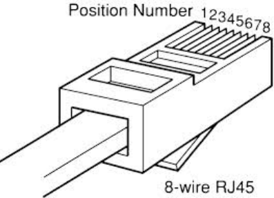
Chapter 5: Preparing for installation Testing system components
Page 5-11
Best Practices for Cabling
The following practices are essential to the reliability and longevity of cabled connections:
• Use only shielded cables to resist interference.
• For vertical runs, provide cable support and strain relief.
• Include a 2-ft (0.6-m) service loop on each end of the cable to allow for thermal expansion and
contraction and to facilitate terminating the cable again when needed.
• Include a drip loop to shed water so that most of the water does not reach the connector at the
device.
• Properly crimp all connectors.
• Use dielectric grease on all connectors to resist corrosion.
• Use only shielded connectors to resist interference and corrosion.
Wiring Connectors
The following diagrams correlate pins to wire colors and illustrate crossovers where applicable.
Pin 1, relative to the lock tab on the connector of a straight-through cable is located as shown
below.
Figure 66 Pin 1 location

Chapter 5: Preparing for installation Testing system components
Page 5-12
Main port pinout
Table 94 Main port pinout
RJ45 pin
Description
1 +TxRx0
2 –TxRx0
3 +TxRx1
4 +TxRx2
5 –TxRx2
6 –TxRx1
7 +TxRx3
8 –TxRx3
Aux port pinout
Table 95 Aux port pinout
RJ45 pin
Description
1 +TxRx0
2 –TxRx0
3 +TxRx1
4 GPS power out, Alignment tone out, GPS data out
5 GPS data in
6 –TxRx1
7 GPS 0v
8 GPS Sync in
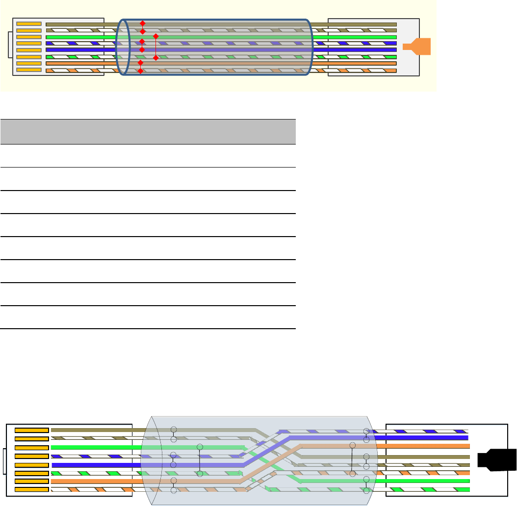
Chapter 5: Preparing for installation Testing system components
Page 5-13
RJ-45 Pinout for Straight-through Ethernet Cable
Figure 67 Straight-through Ethernet Cable
Table 96 RJ-45 pinout for straight-through Ethernet cable
Pin
Signal
Pair
Color
1 TP1+ 2 White/orange stripe
2 TP1- 2 Orange solid
3 TP2+ 3 White/green stripe
4 TP3+ 1 Blue solid
5 TP3- 1 White/blue stripe
6 TP2- 3 Green solid
7 TP4+ 4 White/brown stripe
8 TP4- 4 Brown solid
RJ-45 Pinout for Crossover Ethernet Cable
Figure 68 Crossover Ethernet Cable
1
3
2
4
5
6
7
8
1
3
2
4
5
6
7
8
Hook
Hook Underneath Hook On Top
Crossover Cable
UTP Category 5/6 Cable
``
RJ45 Connector (Bottom)
Straight-Through Cable
RJ45 Connector (Top)
8
7
6
5
4
3
2
1
8
7
6
5
4
3
2
1

Chapter 5: Preparing for installation Testing system components
Page 5-14
Table 97 RJ-45 pinout for crossover Ethernet cable
Pin
Connection 1
Connection 2
Signal
Pair
Color
Signal
Pair
Color
1 TP1+ 2 White/orange stripe TP2+ 3 White/green stripe
2 TP1- 2 Orange solid TP2- 3 Green solid
3 TP2+ 3 White/green stripe TP1+ 2 White/orange stripe
4 TP3+ 1 White/blue stripe TP4+ 4 White/brown stripe
5 TP3- 1 Blue solid TP4- 4 Brown solid
6 TP2- 3 Green solid TP1- 2 Orange solid
7 TP4+ 4 White/brown stripe TP3+ 1 Blue solid
8 TP4- 4 Brown solid TP3- 1 White/blue stripe
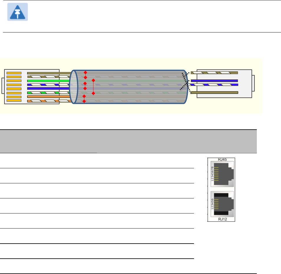
Chapter 5: Preparing for installation Testing system components
Page 5-15
AP/BHM to UGPS cable
The AP/BHM to UGPS cable can be constructed from RJ12 to RJ 45 cable using the pin
configuration described in Table 98.
Note
This is only applicable for 450 AP/BHM.
The AP/BHM will only power up the UGPS if it configured to do so.
Figure 69 AP/BHM to UGPS cable
Table 98 AP/BHM to UGPS cable pinout
Pin
450i Series AP RJ 45
Connector
Pin
UGPS RJ 12 Connector
Connector
1 NC 1 8 on RJ 45
2 NC 2 NC
3 NC 3 5 on RJ 45
4 4 on RJ 12 4 4 on RJ 45
5 3 on RJ 12 5 NC
6 NC 6 7 on RJ 45
7 6 on RJ 12
8 1 on RJ 12
``
RJ45 Connector (Bottom)
Straight-Through Cable
RJ12 Connector (Top)
6
NC 5
4
3
NC 2
1
8
7
6
5
4
3
2
1
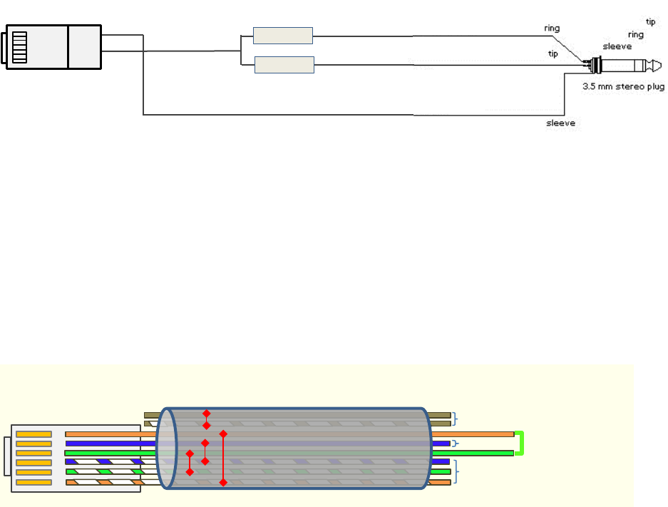
Chapter 5: Preparing for installation Testing system components
Page 5-16
Alignment tone cable (for PMP/PTP 450i)
The alignment tone cable is constructed using RJ45 plug and Stereo plug. The pin configuration is
shown in Figure 70
Figure 70 Alignment tone cable pin configuration
For more information, refer Aux port to alignment tone headset wiring.
Override plug cable (for PMP 450 only)
To construct an override plug, perform the following steps:
• Crimp an RJ-12 6 pins connector onto a 6-inch length of CAT 5 cable
• Pin out all 6 pins
• Short (solder together) pins 4 and 6 on the other end. Do not connect any other wires to
anything.
Figure 71 RJ-12 pinout for the default plug
220 Ω
220 Ω
Resistors
Pin 7
Pin 4
Left
Right
Common
#8
#1
``
RJ12 Connector (Bottom)
Override plug cable wiring
6
5
4
3
2
1
Tie together
Not used
Not used
Not used
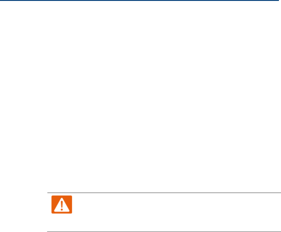
Chapter 5: Preparing for installation Configuring Link for Test
Page 5-17
Configuring Link for Test
It is important to stage the AP/BHM and SM/BHS units first to verify proper registration before
deploying the modules to the site. To begin configuring the modules for test, see the sections
below:
Configuring the management PC
To configure the local management PC to communicate with the AP, SM, BHM or BHS, proceed as
follows:
Powering the AP/SM/BH for test configuration
Perform the following steps to power on the ODU.
Procedure 2 Powering the ODU
1
Plug one end of a CAT 5 Ethernet cable into the ODU.
2
Plug the Ethernet cable connector labeled To Radio into the jack in the pig tail that
hangs from the power supply.
3
Plug the other connector of the pig tail (this connector labeled To Computer) into
the Ethernet jack of the computing device.
4
Plug the power supply into an electrical outlet.
Warning
From this point until you remove power from the ODU, stay at least as
far from the AP as the minimum separation distance specified in
Minimum separation distances on page 5-3.
5
Power up the computing device
6
Start the browser in the computing device
The AP/BHM interface provides a series of web pages to configure and monitor the unit. Access
web-based interface through a computing device that is either directly connected or connected
through a network to the AP/BHM. If the computing device is not connected to a network when it is
being configured for test environment, and if the computer has used a proxy server address and
port to configure a module, then the operator may need to first disable the proxy setting in the
computer.

Chapter 5: Preparing for installation Configuring Link for Test
Page 5-18
Perform the following procedure to toggle the computer to not use the proxy setting.
Procedure 3 Bypassing browser proxy settings to access module web pages
1
Launch Microsoft Internet Explorer
2
Select
Tools, Internet Options, Connections, LAN Settings.
Alternate web browser
menu selections may differ.
3
Uncheck the
Use a proxy server
box.
In the address bar of your browser, enter the IP address of the AP/BHM. (For example, enter
http://169.254.1.1 to access the AP/BHM through its default IP address). The AP/BHM
responds by opening the General Status tab of its Home page.
Logging into the web interface – AP/SM/BH
Procedure 4 Logging into the web interface
1
Plug one end of a CAT 5 Ethernet cable into the AP/BHM
2
Plug the Ethernet cable connector labeled To Radio into the jack in the pig tail that
hangs from the power supply.
3
Plug the other connector of the pig tail (this connector labeled To Computer) into
the Ethernet jack of the computing device.
4
Plug the power supply into an electrical outlet.
Warning
From this point until you remove power from the ODU, stay at least as
far from the ODU as the minimum separation distance specified in
Minimum separation distances on page 5-3.
Using the Quick Start Configuration Wizard of the AP/BHM
See section Quick link setup on page 7-12.
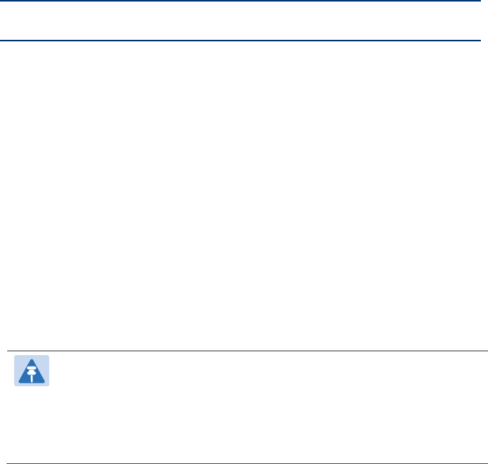
Page 6-1
Chapter 6: Installation
This chapter describes how to install and test the hardware for a 450 Platform link. It contains the
following topics:
• ODU variants and mounting bracket options on page 6-2 provides details of six different
bracket options, including the type of ODU and range of pole diameters supported by each
option.
• Mount the ODU, LPU and surge suppressor on page 6-3 describes how to mount and ground
an integrated or connectorized ODU, how to mount and ground the top LPU.
• Installing the copper Cat5e Ethernet interface on page 6-19 describes how to install the copper
Cat5e power over Ethernet interface from the ODU to the PSU.
• Installing external antennas to a connectorized ODU on page 6-23 describes how to install
external antennas for a connectorized ODU.
• Installing ODU on page 6-58 describes how to install PTP and PMP ODU radios.
• Installing the AC Power Injector on page 6-63 describes how to install a power supply unit for
the PMP/PTP 450 platform, either the AC Power Injector.
• Supplemental installation information on page 6-65 contains detailed installation procedures
that are not included in the above topics, such as how to strip cables, create grounding points
and weatherproof connectors.
Note
These instructions assume that LPUs are being installed from the 450 Platform Family
LPU and grounding kit (Cambium part number C000065L007). If the installation does
not require LPUs, adapt these instructions as appropriate.
If LPUs are being installed, only use the five black-capped EMC cable glands supplied
in the LPU and grounding kit. The silver-capped cable glands supplied in the ODU kits
must only be used in 450 Platform installations which do not require LPUs.

Chapter 6: Installation ODU variants and mounting bracket options
Page 6-2
ODU variants and mounting bracket options
Mounting bracket– PMP/PTP 450i Series
The PMP/PTP 450i Series supports below mentioned mounting bracket option:
Table 99 PMP/PTP 450i Series - ODU mounting bracket part numbers
Cambium description
Cambium part number
Mounting bracket – low profile adjustable N000045L002A
The low profile bracket provides elevation adjustment with the PMP/PTP 450i Series Integrated
ODUs of +10° to –5° or +5° to –10°. A larger adjustment range is available using the standard
integrated mounting bracket. The connectorized mounting bracket does not provide elevation
adjustment.
Mounting bracket– PMP 450 Series – SM 900 MHz
The PMP 450i Series – SM 900 MHz has special mounting bracket option. The PMP 450i Series AP -
900 MHz mounting procedure is the same as the other 450i Series radios. The 450 Series SM 900
MHz has a different mounting bracket which is supplied along with Yagi antenna.
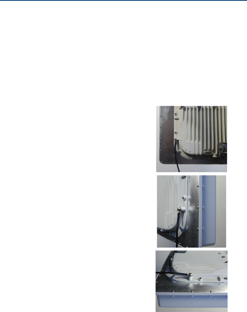
Chapter 6: Installation Mount the ODU, LPU and surge suppressor
Page 6-3
Mount the ODU, LPU and surge suppressor
To install the ODU and top LPU, use the following procedures:
• Attach ground cables to the ODU on page 6-3
• Mount the ODU on the mast on page 6-6
• Mount the top LPU on page 6-10
• Mount the Surge Suppressor on page 6-10
Attach ground cables to the ODU
PMP 450m Series – AP
1
Fasten
an AWG 10 (or 6mm2) copper ground
cable
to each ODU grounding point using the
M6 (small) lugs.
2
Secure
the M6 grounding bolts by applying 3
Nm torque.
.
3
Securely connect the copper wire
s to the
grounding system (Protective Earth)
and the
LPU or Gigabit Ethernet Surge Suppressor
accor
ding to applicable regulations.
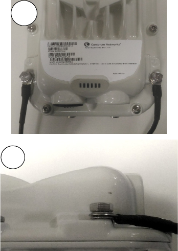
Chapter 6: Installation Mount the ODU, LPU and surge suppressor
Page 6-4
PMP/PTP 450i Series – AP/SM/BH, PMP 450 3GHz Ruggedized SM
1
Fasten
an AWG 10 (or 6mm2) copper ground
cable to each ODU grounding point using the
M6 (small) lugs
.
2
Tighten the Ground post
screws.
3
Securely
connect the copper wires to the grounding system (Protective Earth) and the LPU or
Gigabit Ethernet Surge Suppressor
according to applicable regulations.
2
1
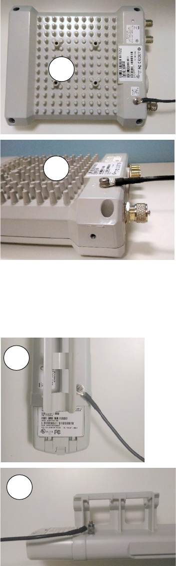
Chapter 6: Installation Mount the ODU, LPU and surge suppressor
Page 6-5
PMP 450 AP
1
Fasten an AWG 10 (or 6mm
2) copper ground
cable to each ODU grounding point using
the
M6 (small) lugs
2
Tighten the Ground post locking nut in the
copper wire
3
Securely connect the copper wire to the grounding system (Protective Earth) according to
applicable regulations.
PMP 450 SM
1
Fasten an AWG 10 (or 6mm
2) copper ground
cable to each ODU grounding point using the
M6 (small) lugs
2
Tighten the Ground post locking nut in the
copper wire
1
2
1
2
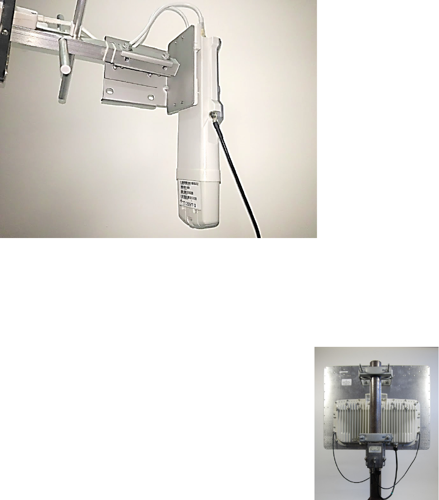
Chapter 6: Installation Mount the ODU, LPU and surge suppressor
Page 6-6
3
Securely connect the copper wire to the grounding system (Protective Earth) according to
applicable regulations.
The grounding point on PMP 450 Series SM 900 MHz is different from 2.4, 3.5/3.65 and 5 GHz PMP
450 SMs as shown in Figure 72.
Figure 72 PMP 450 900 MHz SM grounding
Mount the ODU on the mast
PMP 450m Series – AP
1
See - PMP 450m Series – AP on page 6-51 for
Installation for an integrated ODU
2
Remove the rear bracket strap from upper and lower
brackets of ODU
3
Attach the upper and lower bracket of ODU to the
mount point by closing the rear strap around the pole
4
Secure the four serrated flange M8 nuts by applying
10 Nm torque on upper and lower rear strap using a
13 mm spanner wrench. These must be tightened
evenly on the pole to avoid jumping/stripping threads
Secure the bolts on four sides by applying 8 Nm
torque as per the angle of the antenna.
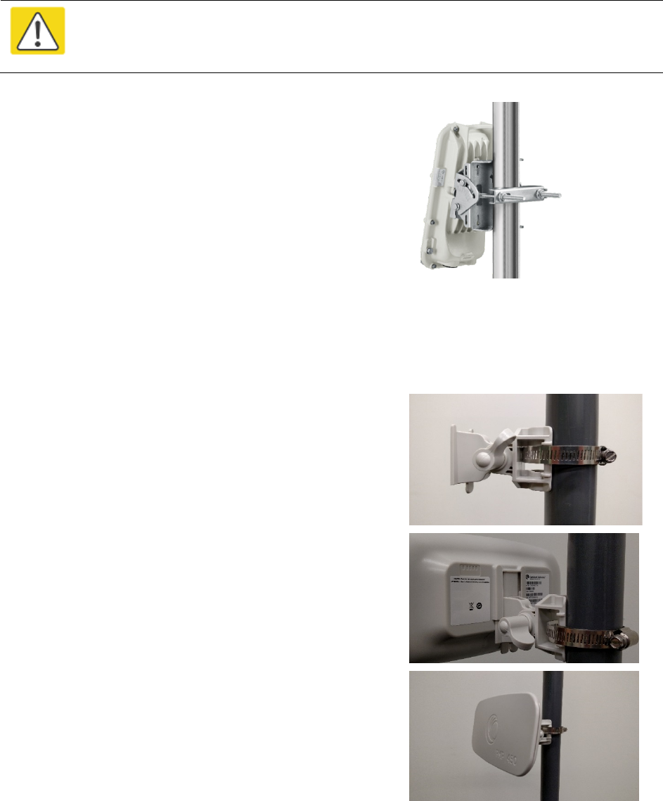
Chapter 6: Installation Mount the ODU, LPU and surge suppressor
Page 6-7
PMP/PTP 450i Series – AP/SM/BH, PMP 450 3 GHz Ruggedized SM
Caution
Do not reverse the bracket clamp, as this arrangement may lead to failure of the
assembly. Do not over-tighten the bolts as this may lead to failure of the assembly.
1
Fix the mounting plate to the back of the ODU using
the four bolts, and spring and plain washers provided.
Tighten the bolts.
2
Attach the bracket body to the mounting plate using
the M8 bolt, spring and plain washers.
3
Hoist the ODU to the mounting position
4
Attach the bracket body to the pole using the bracket
clamp, M8 bolts, and spring and plain washers.
5
Adjust the elevation and azimuth to achieve visual
alignment.
PMP 450b SM
1
Use a stainless steel hose clamp for the attachment.
2
Attach the mounting bracket to the structure with the
release tab facing downward. Tighten the hose clamp.
3
Slide the 450b SM onto the mounting bracket. Press
downwards until it clicks into place.
4
Loosen the adjuster wingnut on the bracket and set
the required SM tilt angle. Retighten the adjuster
wingnut by hand to secure the SM at the chosen
angle.
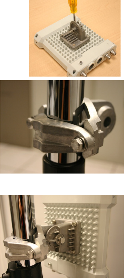
Chapter 6: Installation Mount the ODU, LPU and surge suppressor
Page 6-8
PMP 450 AP
1
Using an 8mm nut driver, attach the pole mount’s
AP housing bracket to the unit using the 4 M5 x
16mm bolts included with the AP.
2
Using the included (depending on pole diameter):
• M8 x 70mm hex cap bolts ( 2 quantity)
or
• M8 x 40mm hex cap bolts ( 2 quantity)
and
• M8 flat washers ( 2 quantity)
• M8 coil washers ( 2 quantity)
Attach the mounting bracket to the pole/mast.
The mounting bracket is designed to attach to
poles with diameters in the range of 2 in. (50mm)
to 3in. (75mm).
3
Complete the AP mounting assembly by attaching
the included:
• 8mm hex cap bolt ( one quantity)
Through the AP’s attached mounting bracket and
pole mount. At this time the AP may be adjusted
to the desired position and tightened with a 1/2
inch spanner wrench to 11 lb/ft (14Nm).
PMP 450 SM (except PMP 450 SM - 900 MHz)
1
Use stainless steel hose clamps for the
attachment.
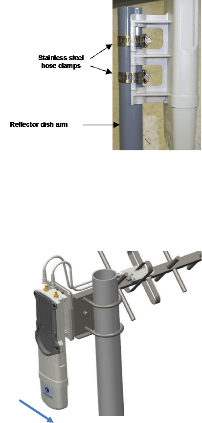
Chapter 6: Installation Mount the ODU, LPU and surge suppressor
Page 6-9
2
Attach the mounting bracket to the structure.
Tighten the locking nut.
PMP 450 SM 900 MHz (connectorized)
The PMP 450 900 MHz connectorized SM mounting procedure is different from other radios. It
does not get directly mounted on pole.
1
Align the 900 MHz SM to E bracket
of Yagi antenna
2
Slide the radio towards right to
lock on the antenna
Slide towards right to lock
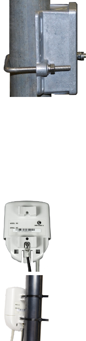
Chapter 6: Installation Mount the ODU, LPU and surge suppressor
Page 6-10
Mount the top LPU
1
For separate LPU mounting, use the U
-bolt
bracket from the LPU kit to mount the top LPU
on the pole below the ODU. Tighten to a torque
setting of 7.0 Nm (5.2 lb ft)
.
Please refer
Gigabit LPU and Grounding Kit
I
nstallation Guide for more details.
Mount the Surge Suppressor
PMP/PTP 450i/450b Series
Gigabit Ethernet Surge Suppressors are installed at both ends of the drop cable. One within 600
mm (24”) of and under the ODU. The other located within 600 mm (24”) of the building entry
point.
Quick procedure:
The quick procedure for the Surge Suppressor for PMP/PTP 450i/450b Series mounting is as
follows:
1
Ground using the terminal on the back of the
units. Use the supplied Tubular Lug and 6 mm2
(10 AWG) stranded cable, max length 600 mm
(24”).
I. Waterproof the cable lug with heat
shrink sleeving.
II. Secure the Cable assembly to the unit using
the supplied screw and washer.
2
Mount the Gigabit Ethernet Surge Suppressor on
the wall or pole
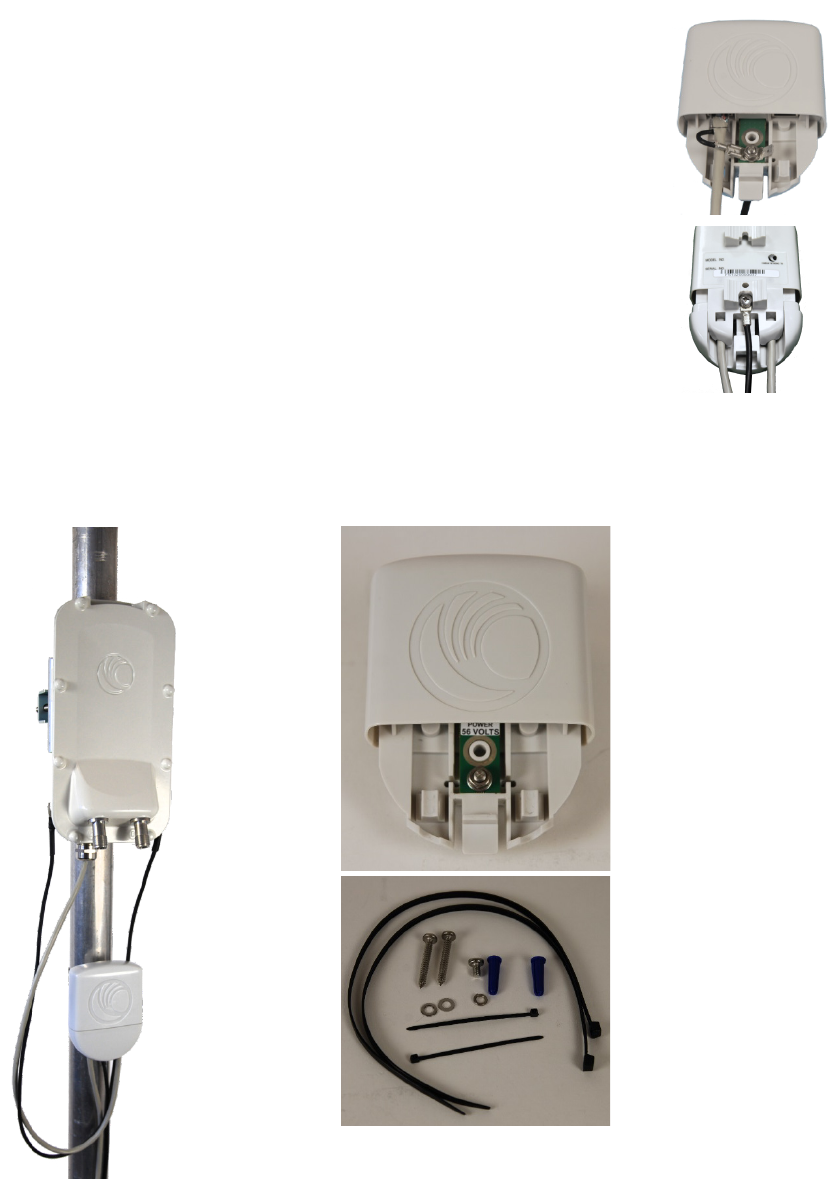
Chapter 6: Installation Mount the ODU, LPU and surge suppressor
Page 6-11
3
Connect the two CAT5e cables to the Gigabit
Ethernet Surge Suppressor
4
Slide the end cap over the bottom of the Gigabit
Ethernet Surge Suppressor, ensuring it clicks
firmly in place
Refer to the Gigabit Ethernet Surge Suppressor Installation Guide for more details.
Figure 73 Gigabit Etherner Surge Suppressor
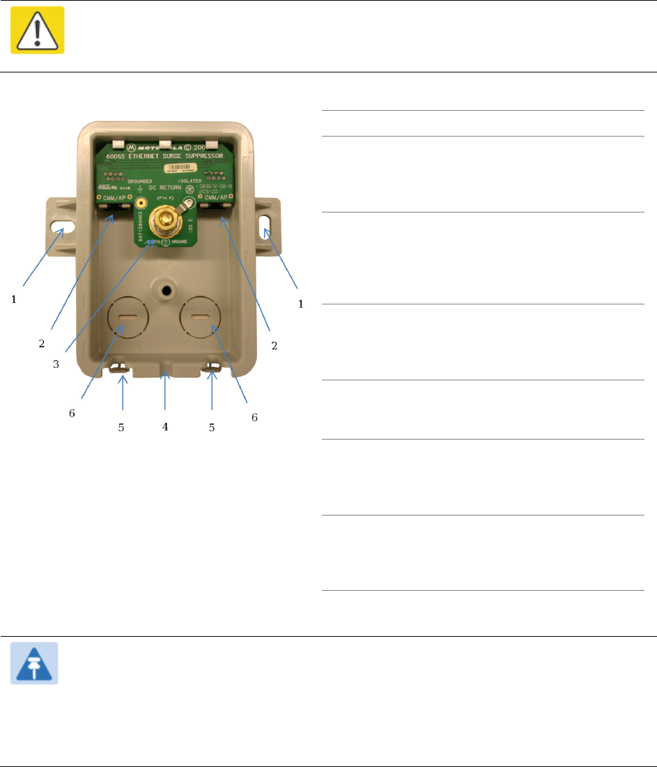
Chapter 6: Installation Mount the ODU, LPU and surge suppressor
Page 6-12
PMP/PTP 450 Series
The PMP/PTP 450 Series uses 600SSH Surge Suppressor. The inside of the surge suppressor is
shown in Figure 74.
Caution
The PMP 450 SM 900 MHz is based off of the 450 Series, be sure to use a 600SS to
protect this radio type.
Figure 74 600SSH Surge Suppressor – inside
Key to Callouts 600SSH
1 Holes—for mounting the Surge
Suppressor to a flat surface (such as an
outside wall). The distance between
centers is 4.25 inches (108 mm).
2 RJ-45 connectors—One side (neither side
is better than the other for this purpose)
connects to the product (AP, SM, AC
Adapter, or cluster management module).
The other connects to the drop cable.
3 Ground post and washer—use heavy
gauge (10 AWG or 6 mm2) copper wire for
connection. Refer to local electrical codes
for exact specifications.
4 Ground Cable Opening—route the 10
AWG (6 mm2) ground cable through this
opening.
5 CAT-5 Cable Knockouts—route the two
CAT-5 cables through these openings, or
alternatively through the Conduit
Knockouts.
6 Conduit Knockouts—on the back of the
case, near the bottom. Available for
installations where cable is routed
through building conduit.
Note
The 600SSH surge suppressor is shipped in the “isolated” position (pin 4 isolated by
68V from protective earth). If packet error issues occur over the Ethernet link (verify by
pinging the device through the 600SSH), configure the 600SSH to “grounded”
position (by moving the 600SSH switch from “isolated” to “ground”) to avoid ground
loops that may be present in the system.
Chapter 6: Installation Mount the ODU, LPU and surge suppressor
Page 6-13
The mounting procedure for the Surge Suppressor for PMP/PTP 450 Series is as follows:
1
Remove the cover of the 600SSH Surge Suppressor.
2
With the cable openings facing downward, mount the 600SSH to the outside of the
subscriber premises, as close to the point where the Ethernet cable penetrates the residence
or building as possible, and as close to the grounding system (Protective Earth) as possible.
3
Wrap an AWG 10 (or 6mm2) copper wire around the Ground post of the 600SSH.
4
Tighten the Ground post locking nut in the 600SSH onto the copper wire.
5
Securely connect the copper wire to the grounding system (Protective Earth) according to
applicable regulations.
6
Using diagonal cutters or long nose pliers, remove the knockouts that cover the cable
openings to the 600SSH.
7
Pack both of the surge suppressor Ethernet jacks with dielectric grease.
8
Wrap a splice loop in the loose end of the Ethernet cable from the SM.
9
Connect that cable to one of the Ethernet jacks.
10
Connect an Ethernet cable to the other Ethernet jack of the 600SSH and to the power adapter.
11
Replace the cover of the 600SSH.
General protection installation
To adequately protect a 450 Platform Family installation, both ground bonding and transient
voltage surge suppression are required.
Grounding cable requirements
When routing, fastening and connecting grounding cables, the following requirements must be
implemented:
• Grounding conductors must be run as short, straight, and smoothly as possible, with the
fewest possible number of bends and curves.
• Grounding cables must not be installed with drip loops.
• All bends must have a minimum radius of 203 mm (8 in) and a minimum angle of 90° (Figure
75). A diagonal run is preferable to a bend, even though it does not follow the contour or run
parallel to the supporting structure.
• All bends, curves and connections must be routed towards the grounding electrode system,
ground rod, or ground bar.
• Grounding conductors must be securely fastened.
• Braided grounding conductors must not be used.
• Approved bonding techniques must be used for the connection of dissimilar metals.
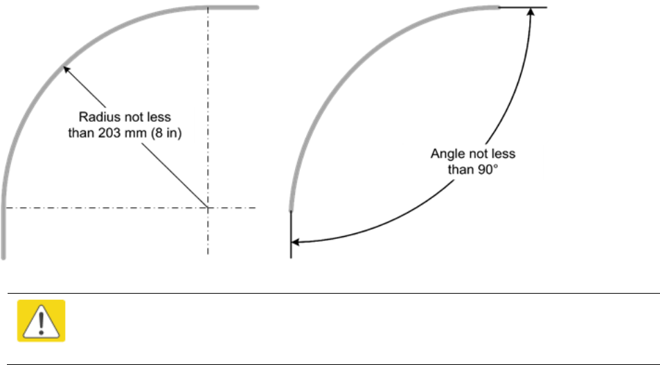
Chapter 6: Installation Mount the ODU, LPU and surge suppressor
Page 6-14
Figure 75 Grounding cable minimum bend radius and angle
Caution
Do not attach grounding cables to the ODU mounting bracket bolts, as this
arrangement will not provide full protection.
Chapter 6: Installation Mount the ODU, LPU and surge suppressor
Page 6-15
Basic requirements
The following basic protection requirements must be implemented:
• ODU must be in ‘Zone B’ (see Lightning protection zones on page 3-9).
• ODU must be grounded to the supporting structure.
• A surge suppression unit must be installed on the outside of the building.
• The distance between the ODU and Gigabit Surge Suppressor should be kept to a minimum.
• The drop cable must not be laid alongside a lightning air terminal.
• All grounding cables must be a minimum size of 10 mm2 csa (8AWG), preferably 16 mm2 csa
(6AWG), or 25 mm2 csa (4AWG).
Protection requirements for a wall installation
If the ODU is to be mounted on the wall of a building, then in addition to the general protection
requirements (above), the following requirements must be observed:
• The equipment must be lower than the top of the building or its lightning air terminal.
• The building must be correctly grounded.
Schematic examples of wall installations are shown in Figure 76.
Figure 76 Grounding and lightning protection on wall
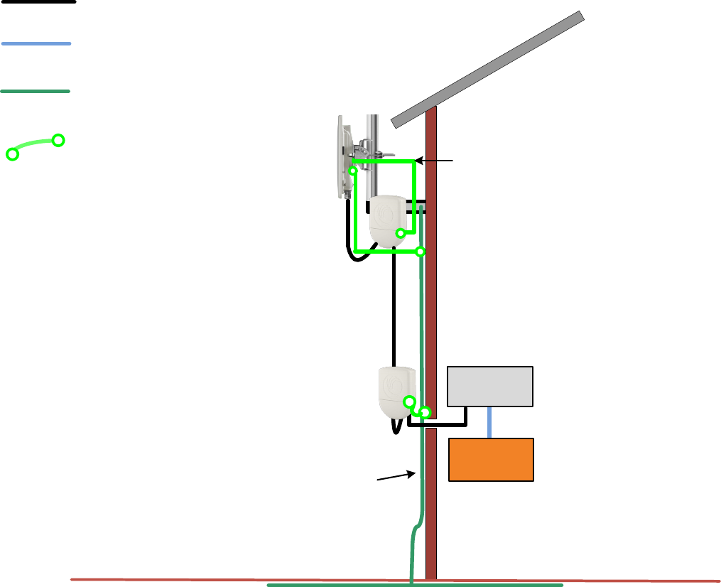
Chapter 6: Installation Mount the ODU, LPU and surge suppressor
Page 6-16
External
ground bar
Ground cable
Ground ring
Outdoor CAT5e cable
Power
Supply
Equipment building
Network
switch
Building ground system
SM/BHS
Cat5e cable
Gigabit Surge Suppressor
Gigabit Surge Suppressor
Ground to opposite-side
ODU grounding lug
Protection requirements for a mast or tower installation
If the ODU is to be mounted on a metal tower or mast, then in addition to the general protection
requirements (above), the following requirements must be observed:
• The equipment must be lower than the top of the tower or its lightning air terminal.
• The metal tower or mast must be correctly grounded.
Schematic examples of mast or tower installations are shown in Figure 77.
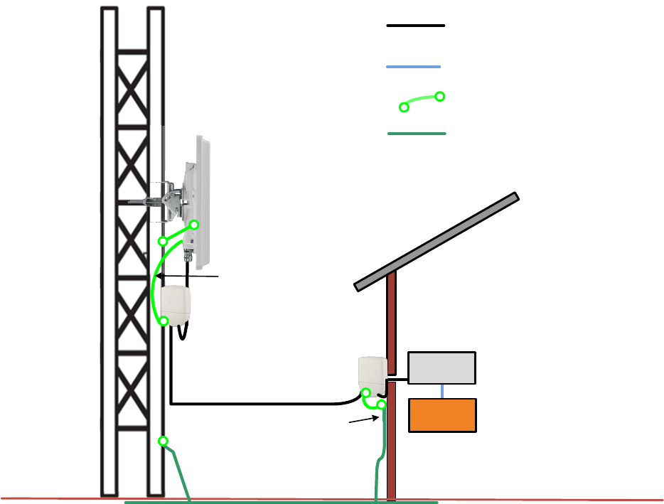
Chapter 6: Installation Mount the ODU, LPU and surge suppressor
Page 6-17
Figure 77 Grounding and lightning protection on mast or tower
External
ground bar
Ground ring
Outdoor CAT5e cable
Power
supply
Equipment building
Network
switch
AP/BHM
Ground Cable
Tower/building ground system
Cat5e cable
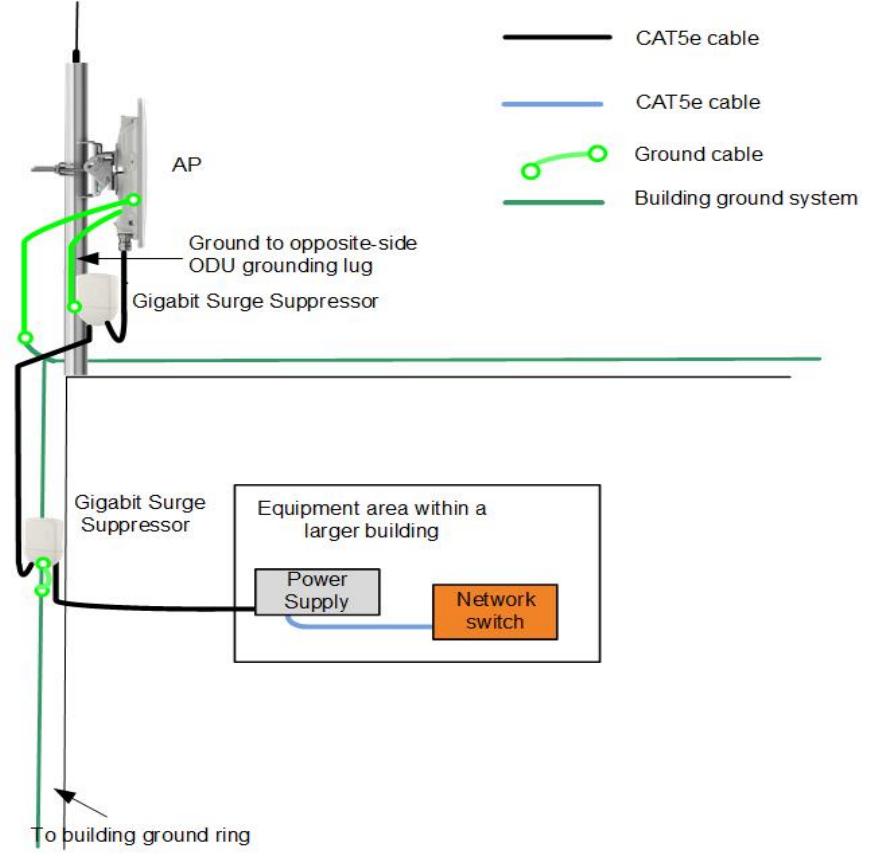
Chapter 6: Installation Mount the ODU, LPU and surge suppressor
Page 6-18
Protection requirements on a multifloor building
If the ODU is to be mounted on a high rise building, it is likely that cable entry is at roof level
(Figure 44) and the equipment room is several floors below. The following additional requirements
must be observed:
• The ODU must be below the lightning terminals and finials.
• A grounding conductor must be installed around the roof perimeter to form the main roof
perimeter lightning protection ring.
• Air terminals are typically installed along the length of the main roof perimeter lightning
protection ring typically every 6.1m (20ft).
• The main roof perimeter lightning protection ring must contain at least two down conductors
connected to the grounding electrode system. The down conductors should be physically
separated from one another, as far as practical.
Figure 78 Grounding and lightning protection on building

Chapter 6: Installation Installing the copper Cat5e Ethernet interface
Page 6-19
Installing the copper Cat5e Ethernet interface
To install the copper Cat5e Ethernet interface, use the following procedures:
• Install the main drop cable on page 6-19
• Install the bottom LPU to PSU drop cable on page 6-21
• Installing external antennas to a connectorized ODU on page 6-23
Caution
To avoid damage to the installation, do not connect or disconnect the drop cable when
power is applied to the PSU or network terminating equipment.
Caution
Always use Cat5e cable that is gel-filled and shielded with copper-plated steel.
Alternative types of Cat5e cable are not supported by Cambium Networks. Cambium
Networks supply this cable (Cambium part numbers WB3175 and WB3176), RJ45
connectors (Cambium part number WB3177) and a crimp tool (Cambium part number
WB3211). The LPU and grounding kit contains a 600 mm length of this cable.
Install the main drop cable
Warning
The metal screen of the drop cable is very sharp and may cause personal injury.
• ALWAYS wear cut-resistant gloves (check the label to ensure they are cut resistant).
• ALWAYS wear protective eyewear.
• ALWAYS use a rotary blade tool to strip the cable (DO NOT use a bladed knife).
Warning
Failure to obey the following precautions may result in injury or death:
• Use the proper hoisting grip for the cable being installed. If the wrong hoisting grip is
used, slippage or insufficient gripping strength will result.
• Do not reuse hoisting grips. Used grips may have lost elasticity, stretched, or become
weakened. Reusing a grip can cause the cable to slip, break, or fall.
• The minimum requirement is one hoisting grip for each 60 m (200 ft) of cable.
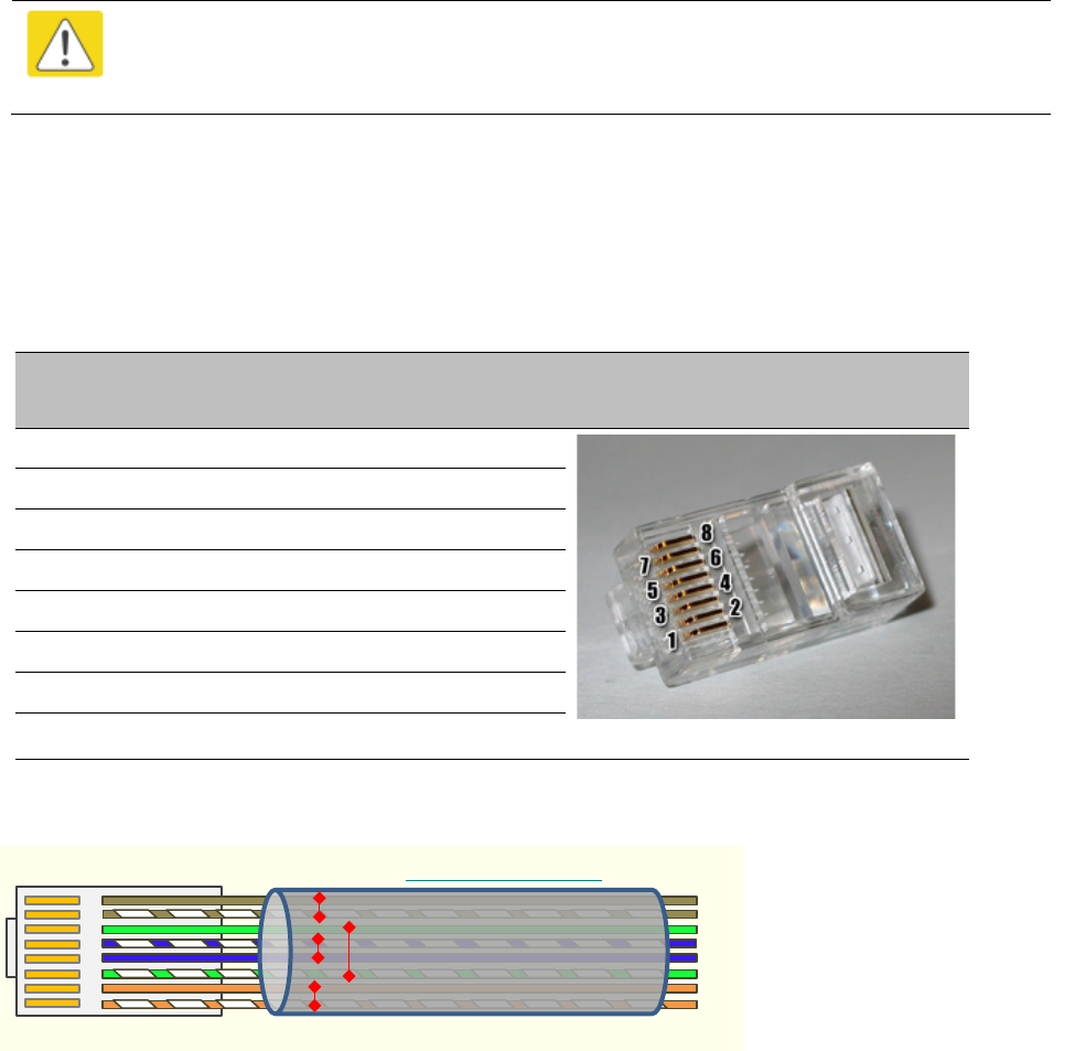
Chapter 6: Installation Installing the copper Cat5e Ethernet interface
Page 6-20
Cut to length and fit hoisting grips
1
Cut the main drop cable to length from the top LPU to the bottom LPU.
2
Slide one
or more hoisting grips onto the top end of the drop cable.
3
Secure the hoisting grip to the cable using a special tool, as recommended by the manufacturer.
Terminate with RJ45 connectors
Caution
Check that the crimp tool matches the RJ45 connector, otherwise the cable or
connector may be damaged.
1
Strip the cable outer sheath and fit the RJ45 connector load bar.
2
Fit
the RJ45 connector housing as shown. To ensure there is effective strain relief, locate the
cable inner sheath under the connector housing tang
.
Table 100 RJ45 connector and cable color code
Pin
Color (Supplied
cable)
Color
(Conventional)
Pins on plug face
1 Light Orange White/Orange
2 Orange Orange
3 Light Green White/Green
4 Blue Blue
5 Light Blue White/Blue
6 Green Green
7 Light Brown White/Brown
8 Brown Brown
Figure 79 RJ45 cable
``
RJ45 Connector (Bottom)
Straight-Through Cable
8
7
6
5
4
3
2
1
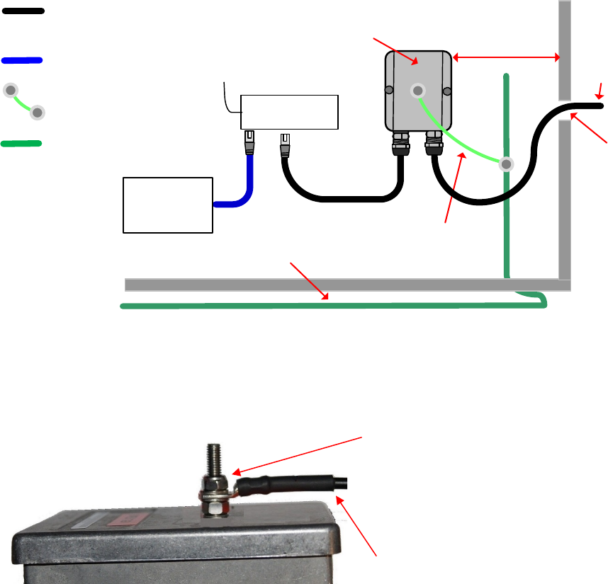
Chapter 6: Installation Installing the copper Cat5e Ethernet interface
Page 6-21
Install the bottom LPU to PSU drop cable
Install the bottom LPU
Install the bottom LPU, ground it, and connect it to the main drop cable.
1
Select a mounting point for the bottom LPU within 600 mm (24 in) of the building entry point.
Mount the LPU vertically with cable glands facing downwards.
Maximum 600 mm
(24 inches)
Bottom LPU
Grounding system
Building
entry
point
LPU to grounding system
PSU drop
cable
PSU
AC supply
Network
terminating
equipment
Ground cables
Power over Ethernet CAT5e
cable (gel-filled, shielded with
copper-plated steel)
Network CAT5e cable
Site grounding system
2
Connect the main drop cable using the EMC cable gland to the bottom LPU.
3
Fasten one ground cable to the bottom LPU using the M6 (small) lug. Tighten both nuts to a
torque of 5 Nm (3.9 lb ft):
Locking nut
Washer
M6 lug
Washer
Nut
Toothed washer
Other end of ground cable has M10 lug
to ground
4
Select a building grounding point near the LPU bracket. Remove paint from the surface and
apply anti-oxidant compound. Fasten the LPU ground cable using the M10 (large) lug.
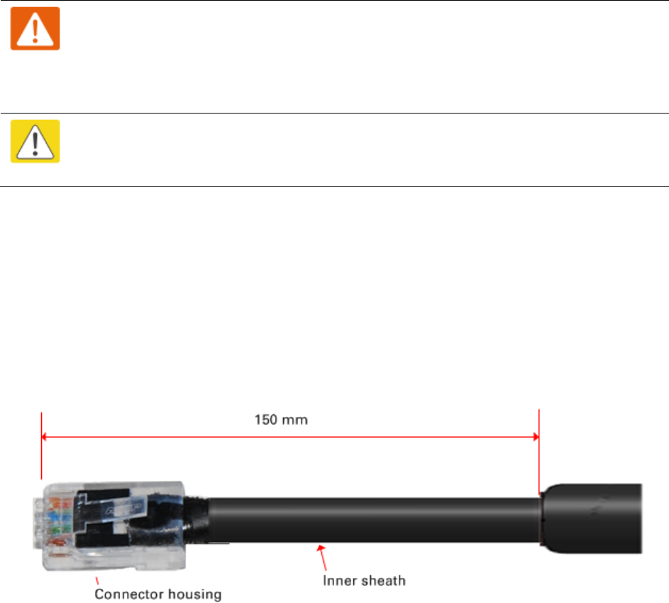
Chapter 6: Installation Installing the copper Cat5e Ethernet interface
Page 6-22
Install the LPU to PSU drop cable
Use this procedure to terminate the bottom LPU to PSU drop cable with RJ45 connectors at both
ends, and with a cable gland at the LPU end.
Warning
The metal screen of the drop cable is very sharp and may cause personal injury.
ALWAYS wear cut-resistant gloves (check the label to ensure they are cut resistant).
ALWAYS wear protective eyewear. ALWAYS use a rotary blade tool to strip the cable,
not a bladed knife.
Caution
Check that the crimp tool matches the RJ45 connector, otherwise the cable or
connector may be damaged.
1
Cut the drop cable to the length required from bottom LPU to PSU.
2
At the LPU end only
:
•
Fit one cable gland and one RJ45 connector by following the procedure Terminate with
RJ45 connectors on page 6-20.
•
Connect this cable and gland to the bottom LPU.
3
At the PSU end only
: Do not fit a cable gland. Strip the cable outer sheath and fit the RJ45
connector load bar. Fit the RJ45 connector housing. To ensure there is effective strain relief,
locate the cable inner sheath under the connector housing tang:
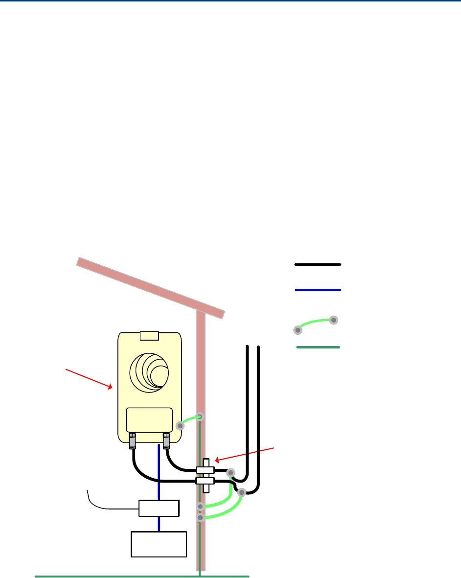
Chapter 6: Installation Installing external antennas to a connectorized ODU
Page 6-23
Installing external antennas to a connectorized ODU
PMP 450i Series
To mount and connect an external antenna to the connectorized ODU, proceed as follows:
1
M
ount the antenna(s) according to manufacturer’s instructions.
2
Connect the ODU
A and B interfaces to the antenna(s) with RF cable of type LMR-400 (Cambium
part
numbers 30010194001 and 30010195001) and N type connectors (Cambium part number
09010091001). Tighten the
N type connectors to a torque setting of 1.7 Nm (1.3 lb ft).
3
If
the ODU is mounted indoors, install lightning arrestors at the building entry point:
4
Form
drip loops near the lower ends of the antenna cables. These ensure that water is not
channeled towards the connector
s.
5
If the ODU is mounted outdoors, weatherproof the N type connectors (when antenna alignment
is complete) using PVC tape and
self-amalgamating rubber tape.
6
Weatherproof the antenna connectors in the same way (unless the antenna manufacturer
specifies a different method).
PSU
Network
equipment
CAT5e cable
Ground ring
RF cables to
antenna
AC supply
Lightning arrestors
Equipment building
or cabinet
RF cable
Connectorized
ODU
AB
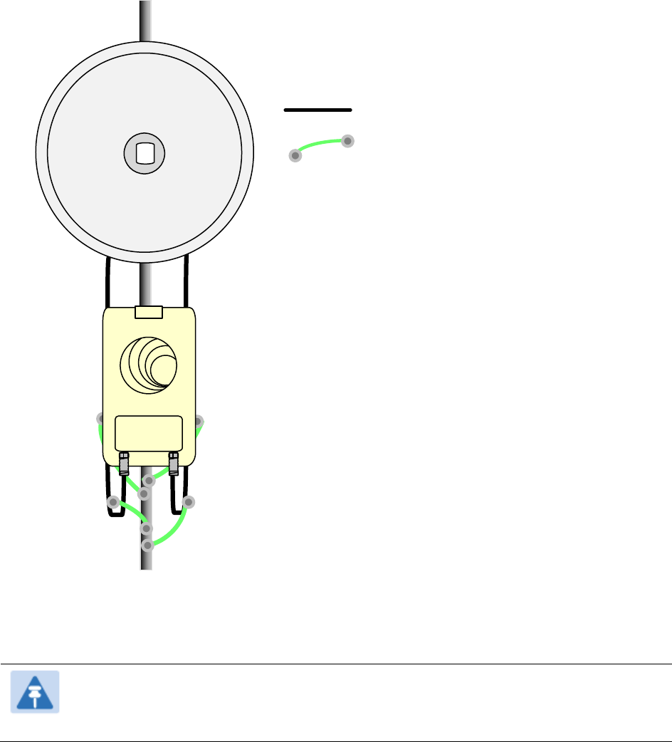
Chapter 6: Installation Installing external antennas to a connectorized ODU
Page 6-24
7
Ground the
antenna cables to the supporting structure within 0.3 meters (1 foot) of the ODU and
antennas using the Cambium grounding kit (
part number 01010419001):
Connectorized ODU
AB
PMP/PTP 450i ground
cable
RF cable
Antenna
8
Fix the antenna cables to the supporting structure using site approved
methods. Ensure that no
undue strain is placed on the ODU or antenna connectors. Ensure that the cables do not flap in
the wind, as flapping cables are prone to damage and induce unwanted vibrations in the
supporting structure.
Note
A video on weatherproofing procedure can be found at:
https://www.youtube.com/watch?v=a-twPfCVq4A
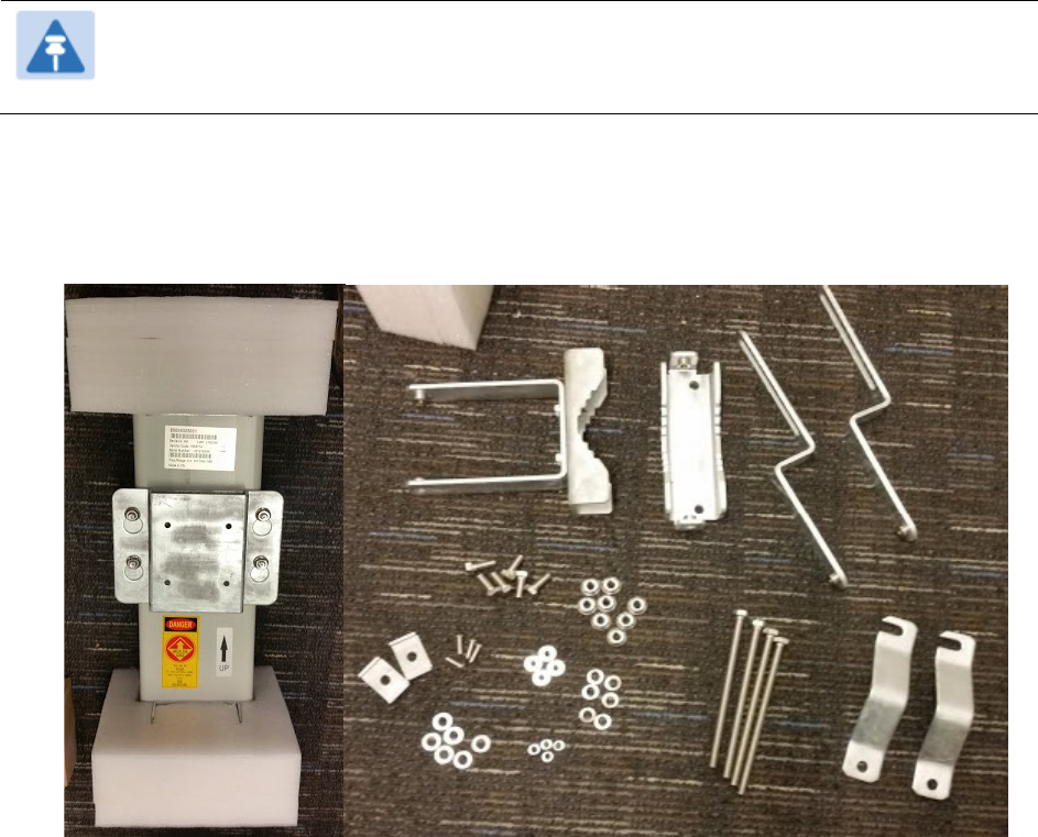
Chapter 6: Installation Installing external antennas to a connectorized ODU
Page 6-25
Assembling the PMP 450i AP 5 GHz sector antenna and attaching to the
radio
To assemble a PMP 450i Series AP antenna, perform the following steps.
Note
Cambium recommends to assemble the antenna, attach the AP and cabling, and to
seal the RF connections before installing the unit at the deployment site.
1
Inventory the parts to ensure that you have them all before you begin. The full set of parts
is shown below.
Figure 80
AP antenna parts
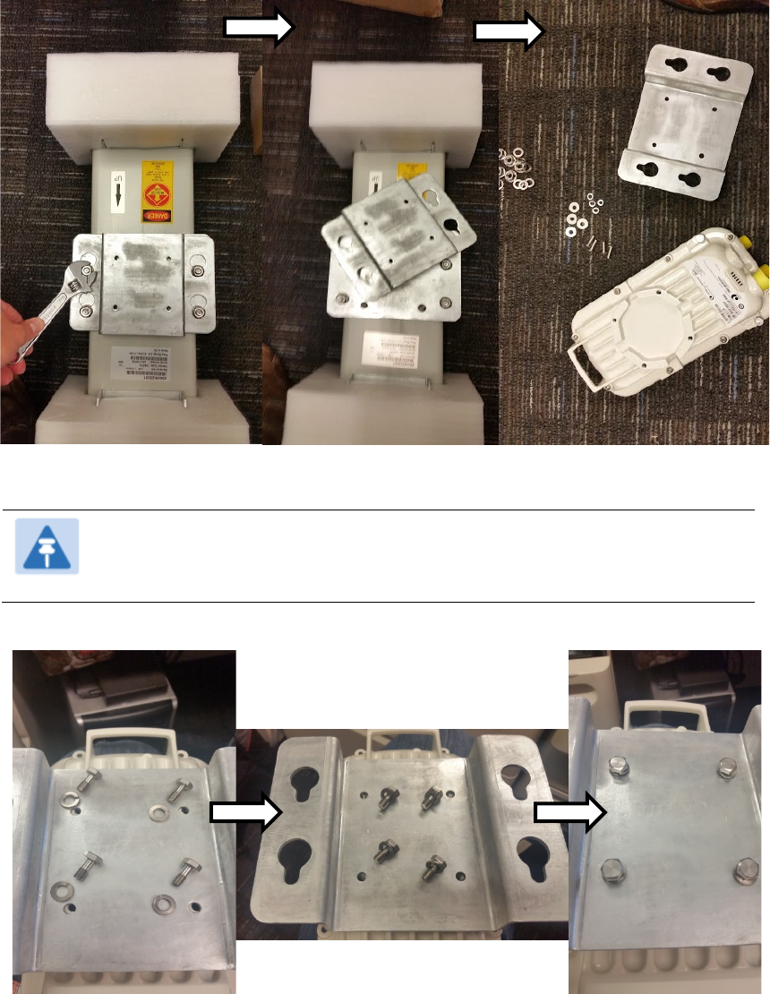
Chapter 6: Installation Installing external antennas to a connectorized ODU
Page 6-26
2
Remove top plate from the antenna as shown in Figure 81.
Figure 81
Antenna top plate
3
Attach the antenna plate to the AP as shown in Figure 82.
Note
Please use the four “thin neck” M6 bolts and split washers provided with
the connectorized units rather that the ones provided in the antenna kit.
Figure 82
Attaching antenna plate to the AP
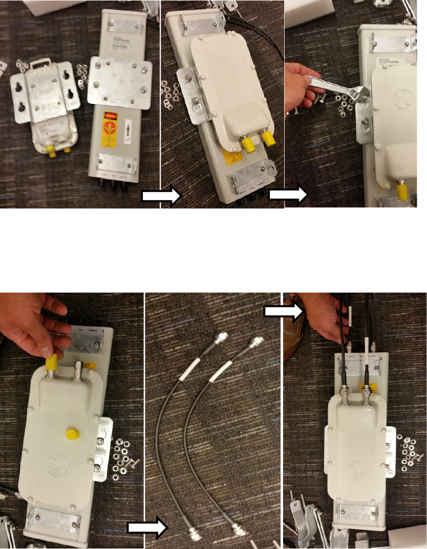
Chapter 6: Installation Installing external antennas to a connectorized ODU
Page 6-27
4
Attach the plate mounted AP to the antenna and tighten the (4) serrated flange nuts using
a spanner wrench
Figure 83
Attaching the plate
5
Connect the port A of AP to vertical and port B of AP to horizontal polarization interfaces of
the antenna with RF cable. Tighten the N type connectors to a torque setting of 1.7 Nm (1.3
lb ft).
Figure 84
Connect the port A and B to the PMP 450i AP
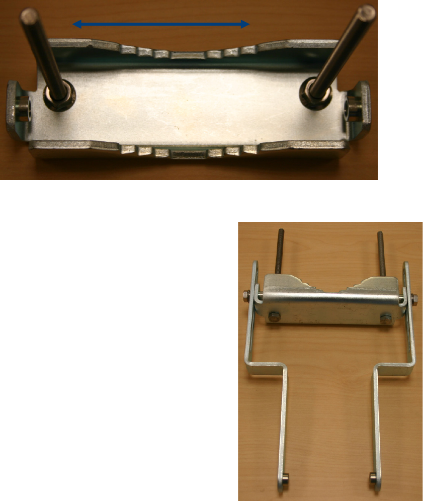
Chapter 6: Installation Installing external antennas to a connectorized ODU
Page 6-28
6
Assemble the upper bracket by attaching the (2) 7” hex bolts to the bracket using (2)
serrated flange nuts
Figure 85
AP antenna upper bracket assembly
7
Attach the upper bracket to the adjustment
arms using (2) hex bolts, (2) flat washers and
(2) lock washers. Feed the bolt through the
lock washer then flat washer, then thread the
bolt into the upper bracket’s threaded
receptacle.
Figure 86
AP antenna upper bracket
attached to upper adjustment arms
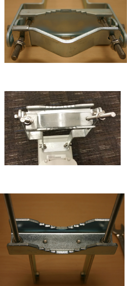
Chapter 6: Installation Installing external antennas to a connectorized ODU
Page 6-29
8
Attach the rear strap to the upper bracket
using (2) serrated flange nuts and (1)
retaining bracket. Do not tighten the nuts
now.
Figure 87
Rear strap connected to upper
AP antenna bracket
9
Attach the entire upper bracket to the
antenna using (2) hex bolts, (2) flat washers
and (2) lock washers. Feed the bolt through
the lock washer then flat washer, then thread
the bolt into the upper bracket’s threaded
receptacle.
Figure 88
Assembled upper bracket
connected to AP antenna
10
Begin assembling the lower bracket by
attaching the (2) 7” hex bolts to the bracket
using (2) serrated flange nuts
Figure 89
AP Antenna Lower Bracket
Assembly
11
Attach the rear strap to the bracket using (2) serrated flange nuts and (1) retaining bracket.
Do not tighten the nuts now.
Attach the entire lower bracket to the antenna using (2) hex bolts, (2) flat washers and (2)
lock washers.
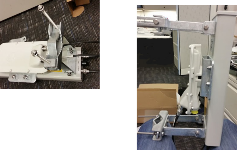
Chapter 6: Installation Installing external antennas to a connectorized ODU
Page 6-30
Figure 90
Lower bracket attached to AP
antenna
Figure 91
Completed AP and antenna
assembly