Acrodyne NW8201E DIGITAL TELEVISION BROADCAST TRANSMITTER User Manual 32 NV8202 26 04 06 01 00
Acrodyne Industries, Inc. DIGITAL TELEVISION BROADCAST TRANSMITTER 32 NV8202 26 04 06 01 00
Acrodyne >
Contents
- 1. Users Manual Part 1
- 2. Users Manual Part 2
- 3. Users Manual Part 3
- 4. Users Manual Part 4
- 5. Users Manual Part 5
- 6. Users Manual Part 6
- 7. Users Manual Part 7
- 8. Users Manual Part 8
- 9. Users Manual Part 9
- 10. Users Manual Part 10
- 11. Users Manual Part 11
- 12. USers Manual Part 12
- 13. Users Manual Part 13
- 14. Users Manual Part 14
- 15. Users Manual Part 15
- 16. Users Manual Part 16
- 17. Users Manual Part 17
- 18. Users Manual Part 18
- 19. Users Manual Part 19
- 20. Users Manual Part 20
USers Manual Part 12
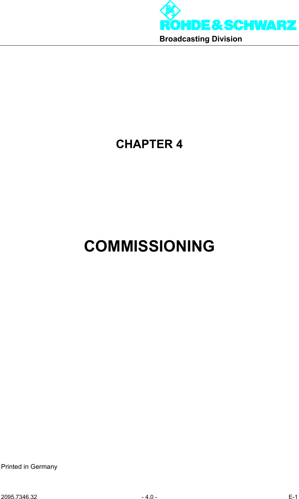
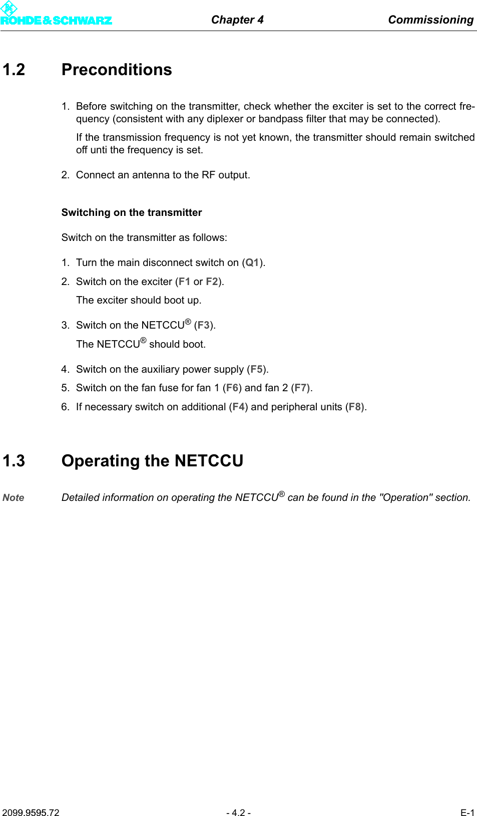
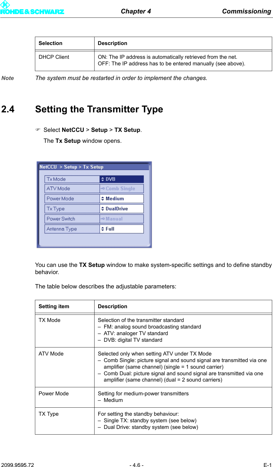
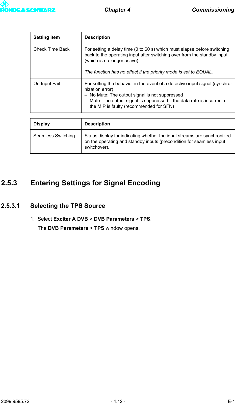
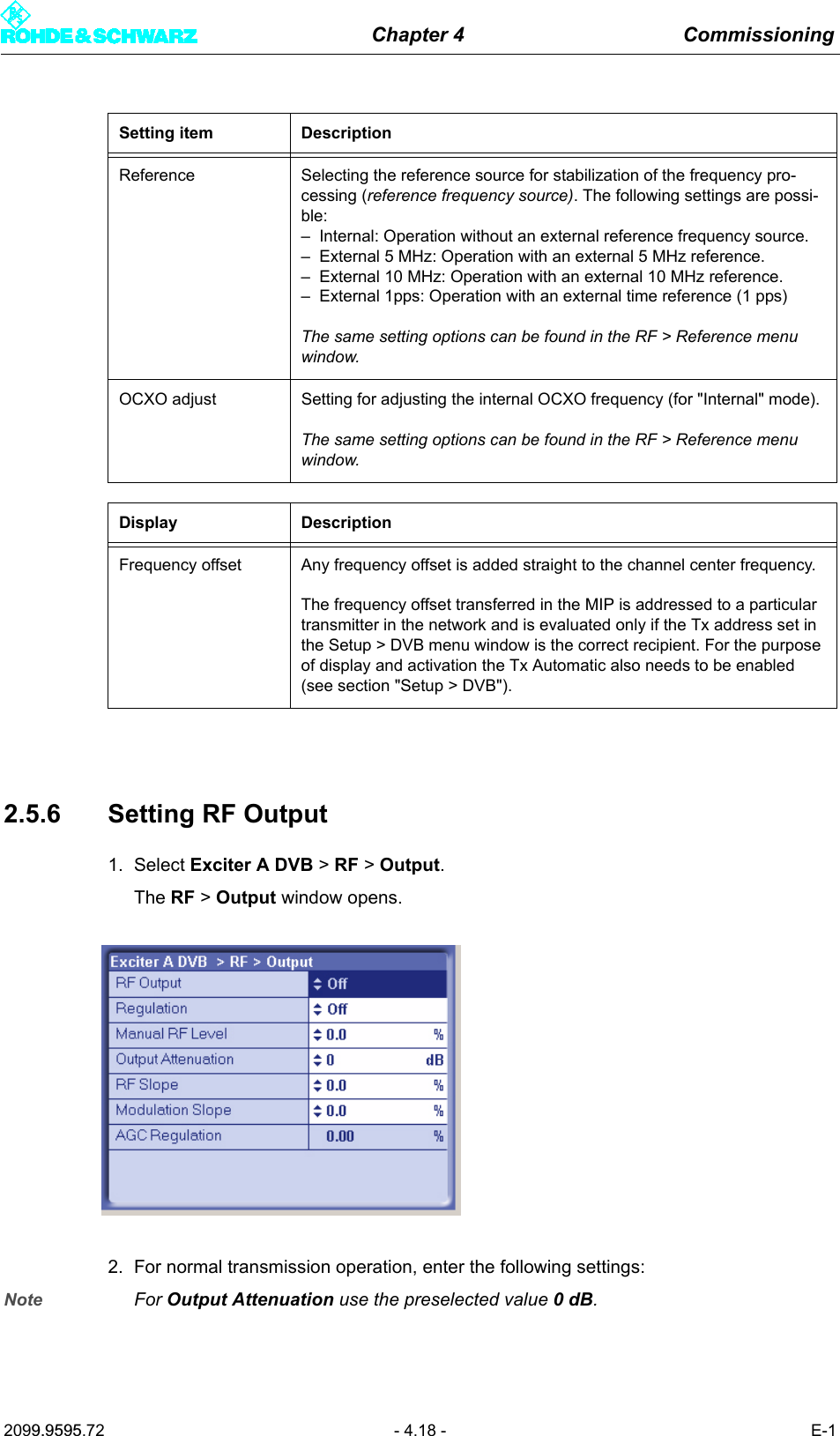
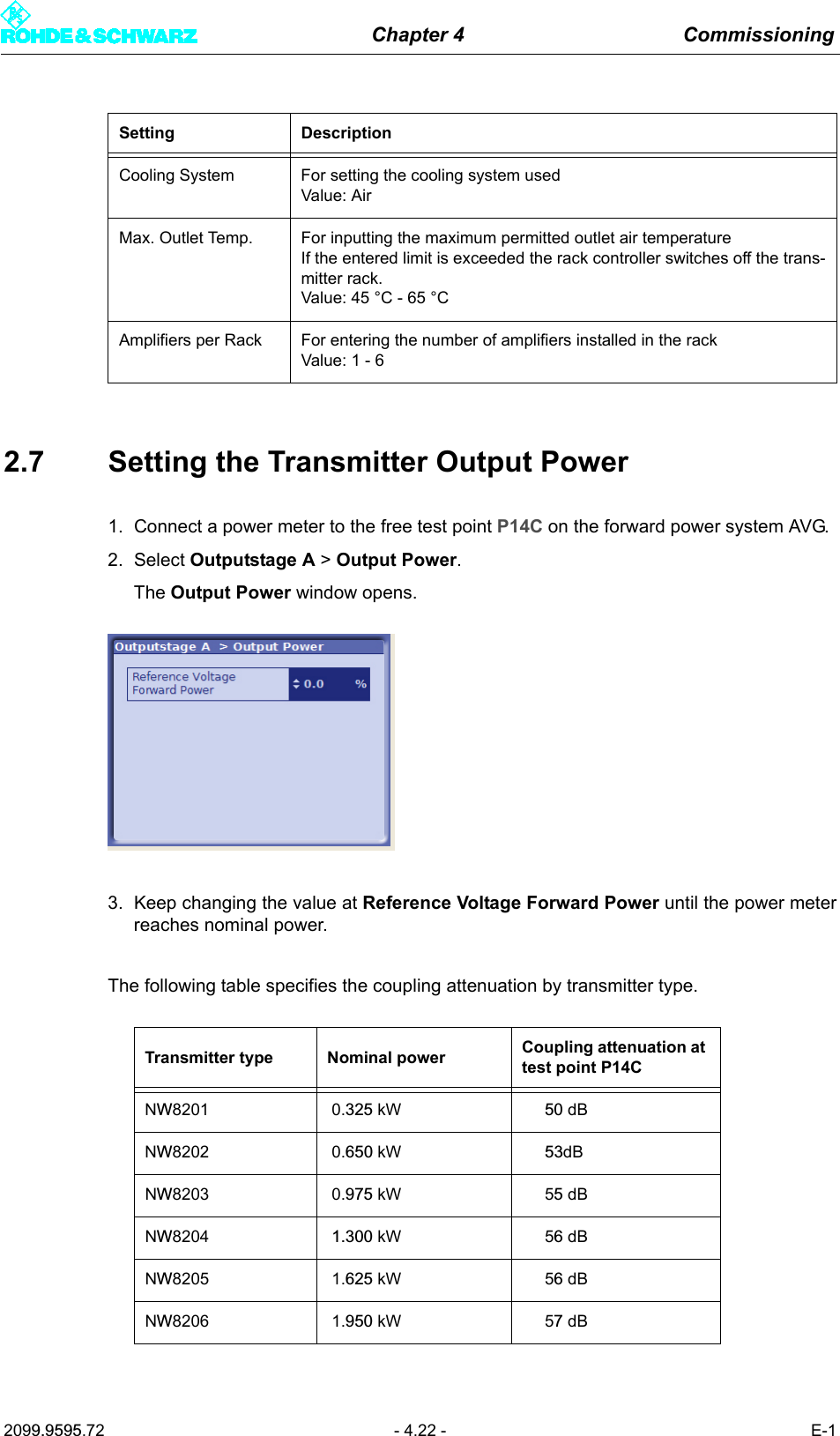
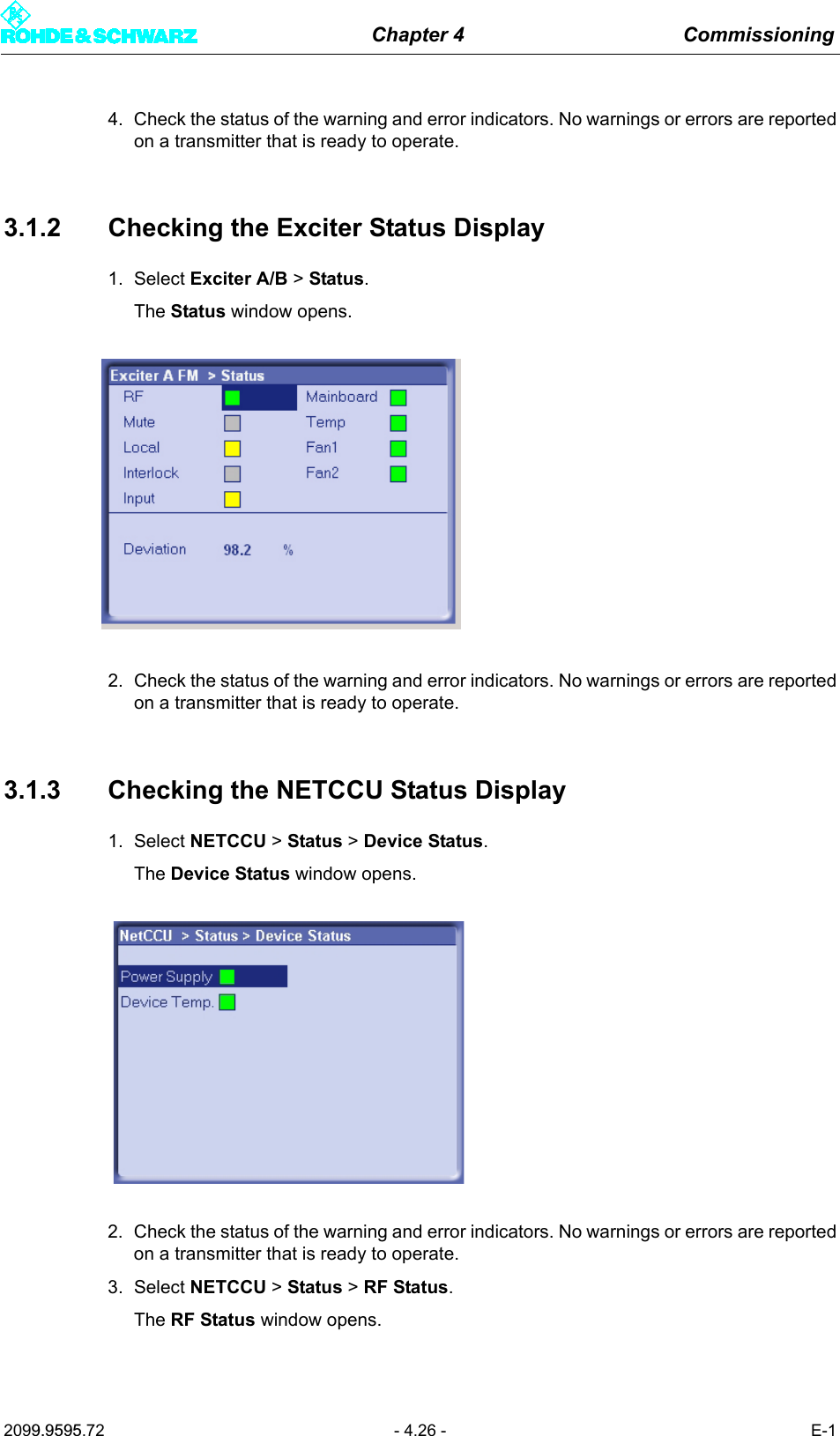
![Chapter 4 Commissioning2099.9595.72 - 4.9 - E-12.5.2.2 Specifying the Data Format for Low Priority Data Streams LP 1 or LP 21. Select Exciter A DVB > Input > Input Config LP.The Input > Input Config LP window opens.Setting item DescriptionPresel. Mode[Input HP1/Input HP2]Setting the data format for the data streams HP 1 or HP 2 (operating and standby signals) on inputs TS 1 IN or TS 3 IN.The options are as follows:– AUTO: The data format is automatically recognized– ASI: Manual setting for an ASI transport stream– SMPTE: Manual setting for a SMPTE transport streamIn the case of hierarchical coding the operating or standby signal for the high priority (HP) stream is fed via the two inputs HP 1 and/or HP 2.Display DescriptionPacket Length[Input HP1/Input HP2]Display showing the packet length detected at the respective inputMeas.Data Rate [bps][Input HP1/Input HP2]Display showing the measured data rate at the respective input. In MFN mode the net data rate is displayed (without null packets).Req. Data Rate [bps][Input HP1/Input HP2]Display for checking the measured data rate. Depending on the chosen network mode, the following information is displayed:–MFN: Maximum data processing rate–SFN: Required data rateActive Mode Display showing the data format detected or set at the respective input:– ASI: As described– SMTPE: As described– Auto: Auto is selected and there is no data stream](https://usermanual.wiki/Acrodyne/NW8201E.USers-Manual-Part-12/User-Guide-864568-Page-13.png)
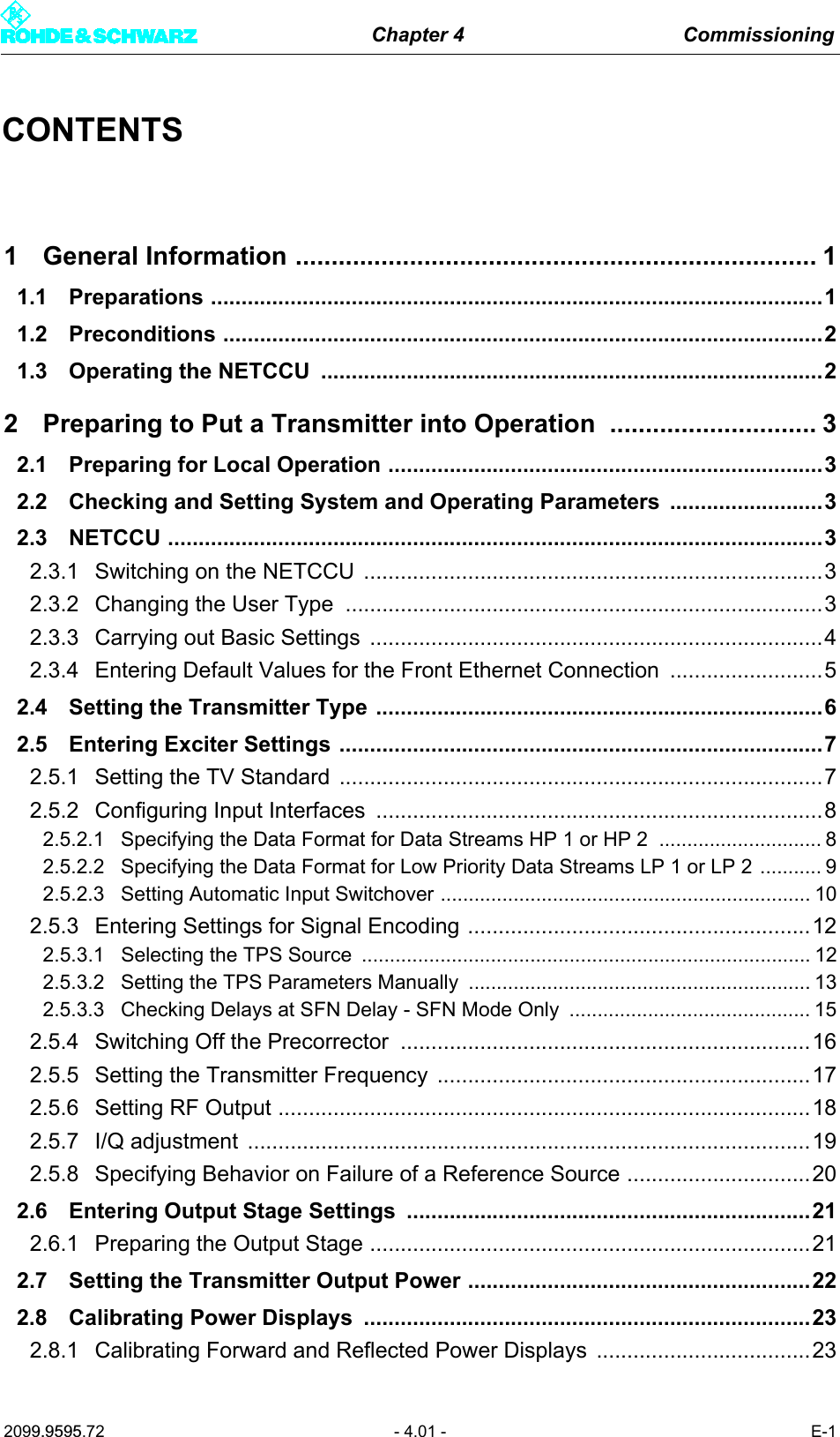
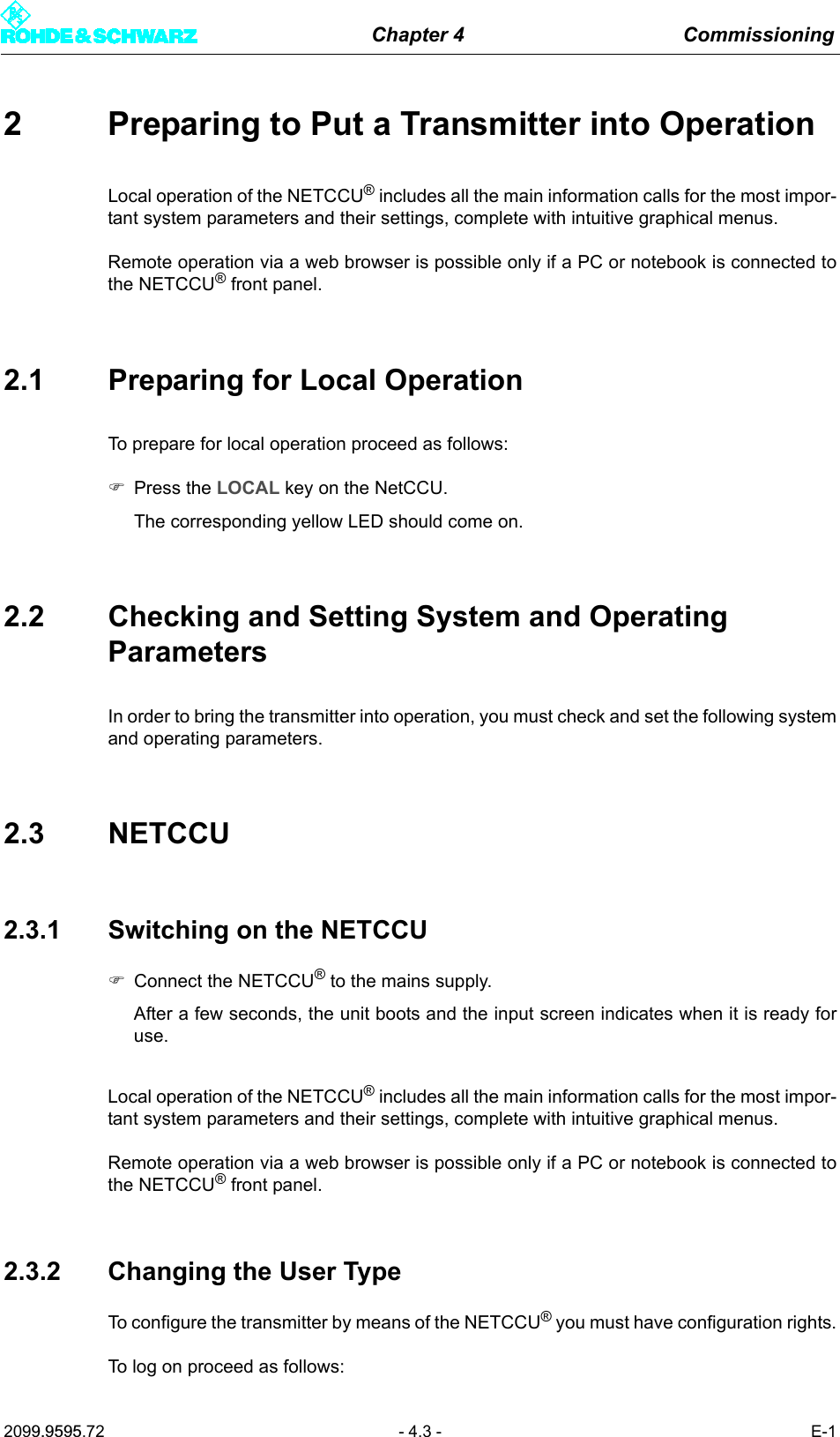
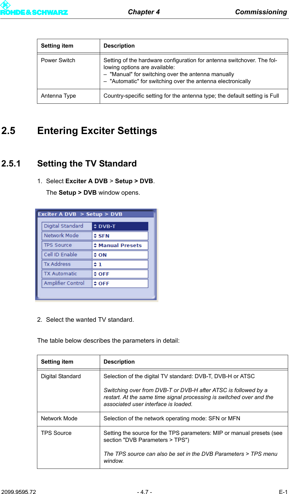
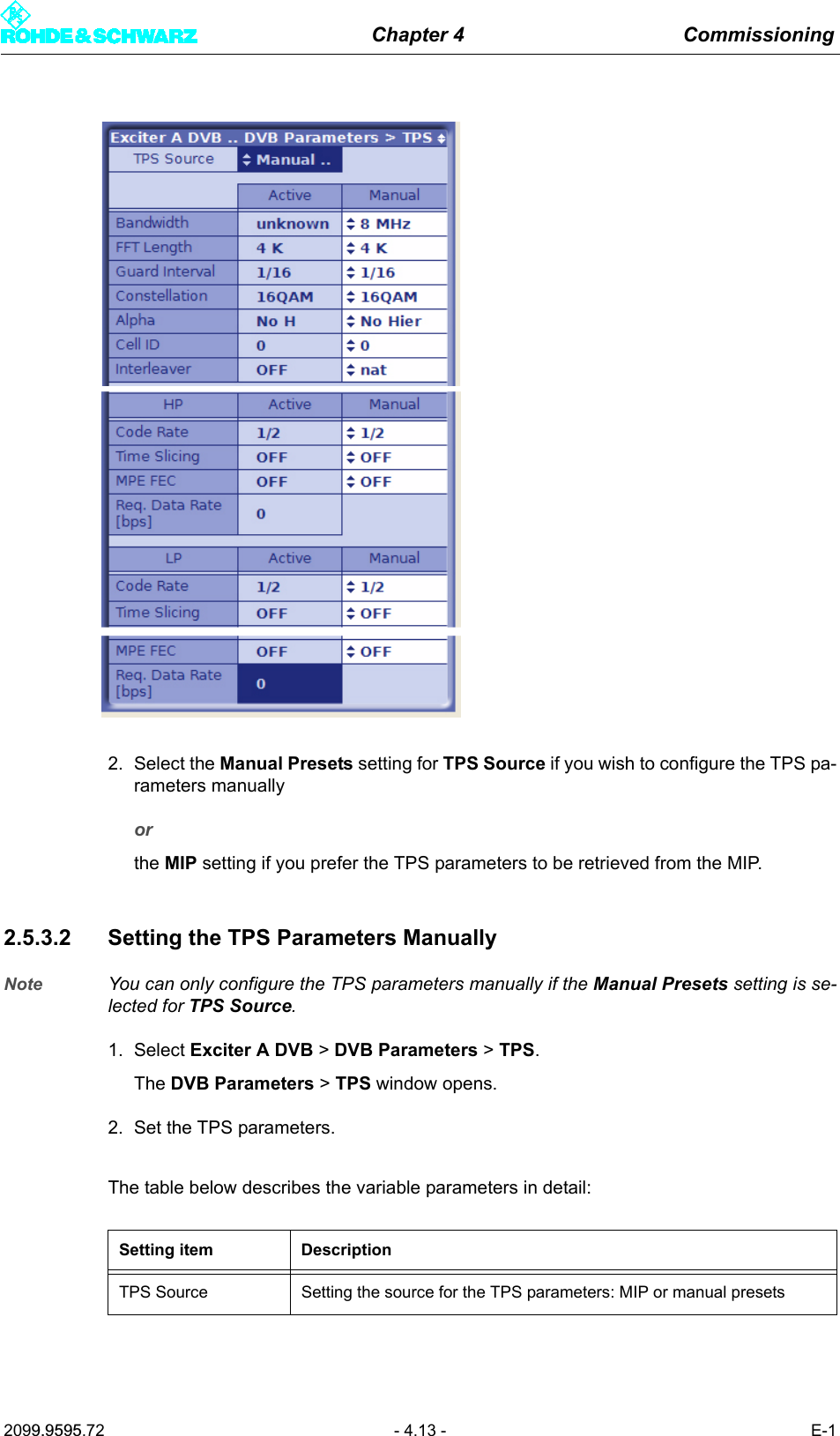
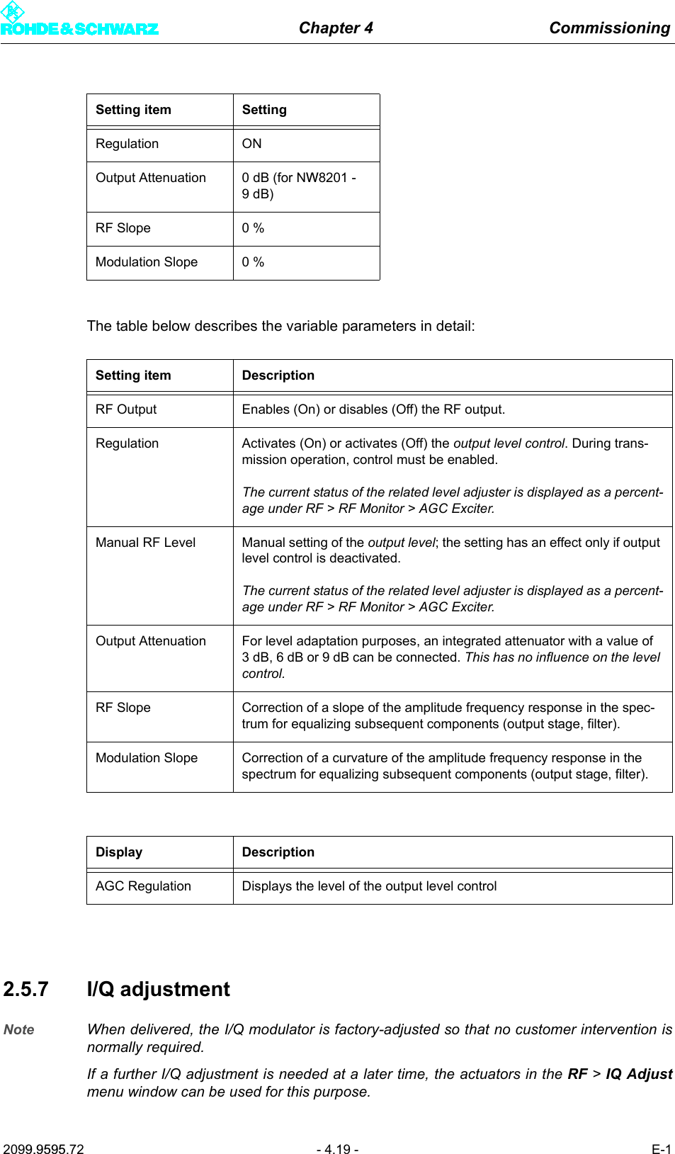
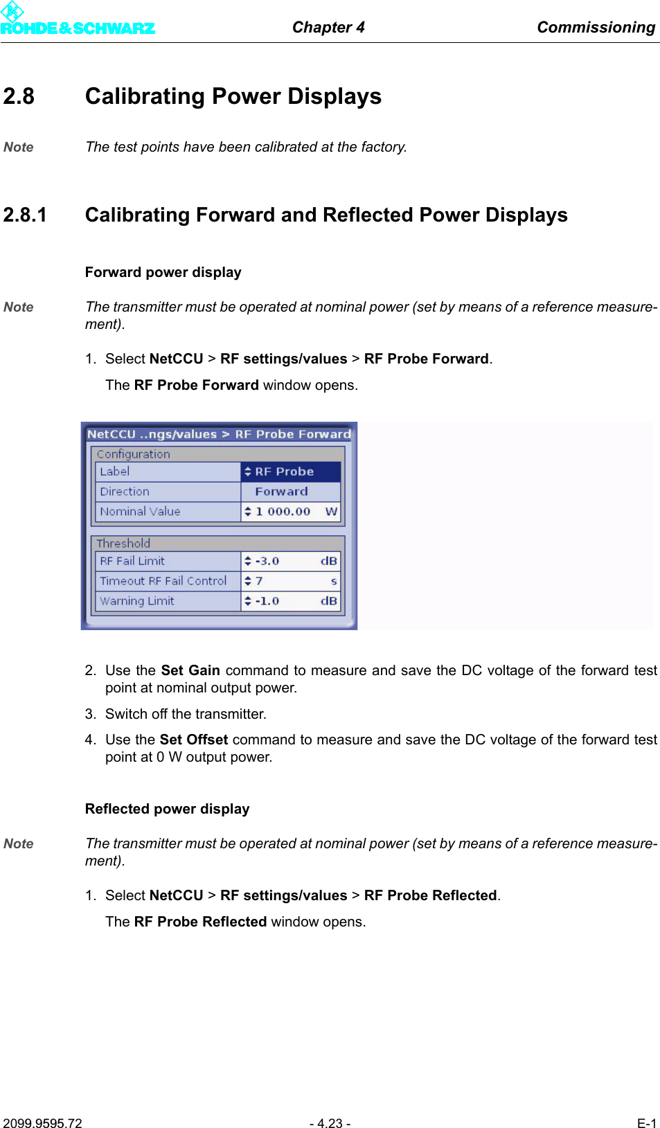
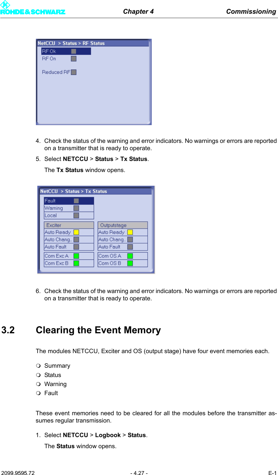
![Chapter 4 Commissioning2099.9595.72 - 4.10 - E-12. Go to Presel. Mode and select the value Auto for Input LP 1 and Input LP 2.The data format is recognized automatically.The table below describes the parameters in detail:2.5.2.3 Setting Automatic Input Switchover1. Select Exciter A DVB > Input > Input Automatic.The Input > Input Automatic window opens.Setting item DescriptionPresel. Mode[Input LP1/Input LP2]In the case of hierarchical coding: Setting the data format for the low pri-ority data streams LP 1 or LP 2 (operating and standby signals) on inputs TS 2 IN or TS 4 IN.The options are as follows:– AUTO: The data format is automatically recognized– ASI: Manual setting for an ASI transport stream– SMPTE: Manual setting for a SMPTE transport streamDisplay DescriptionPacket Length[Input LP1/Input LP2]Display showing the packet length detected at the respective inputMeas.Data Rate [bps][Input LP1/Input LP2]Display showing the measured data rate at the respective input. In MFN mode the net data rate is displayed (without null packets).Req. Data Rate [bps][Input LP1/Input LP2]Display for checking the measured data rate. Depending on the chosen network mode, the following information is displayed:–MFN: Maximum data processing rate–SFN: Required data rateActive Mode Display showing the data format detected or set at the respective input:– ASI: As described– SMTPE: As described– Auto: Auto is selected and there is no data stream](https://usermanual.wiki/Acrodyne/NW8201E.USers-Manual-Part-12/User-Guide-864568-Page-14.png)
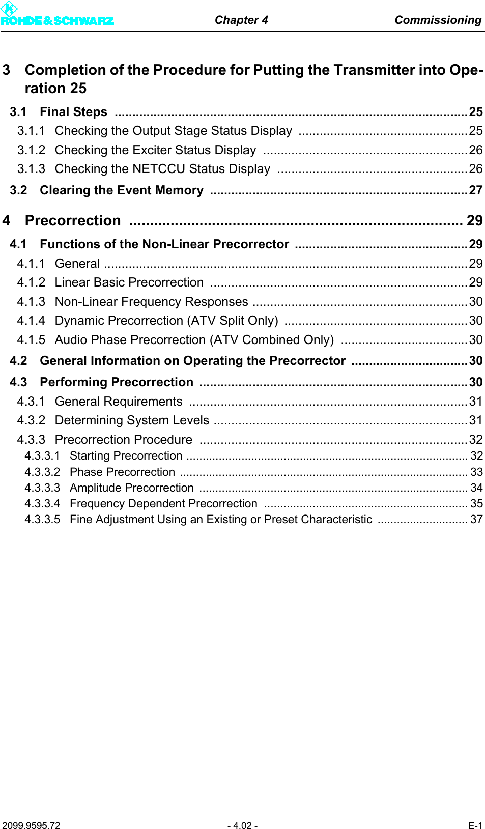
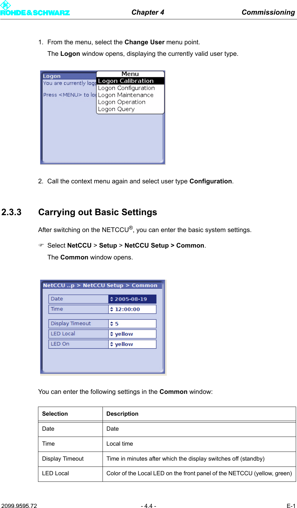
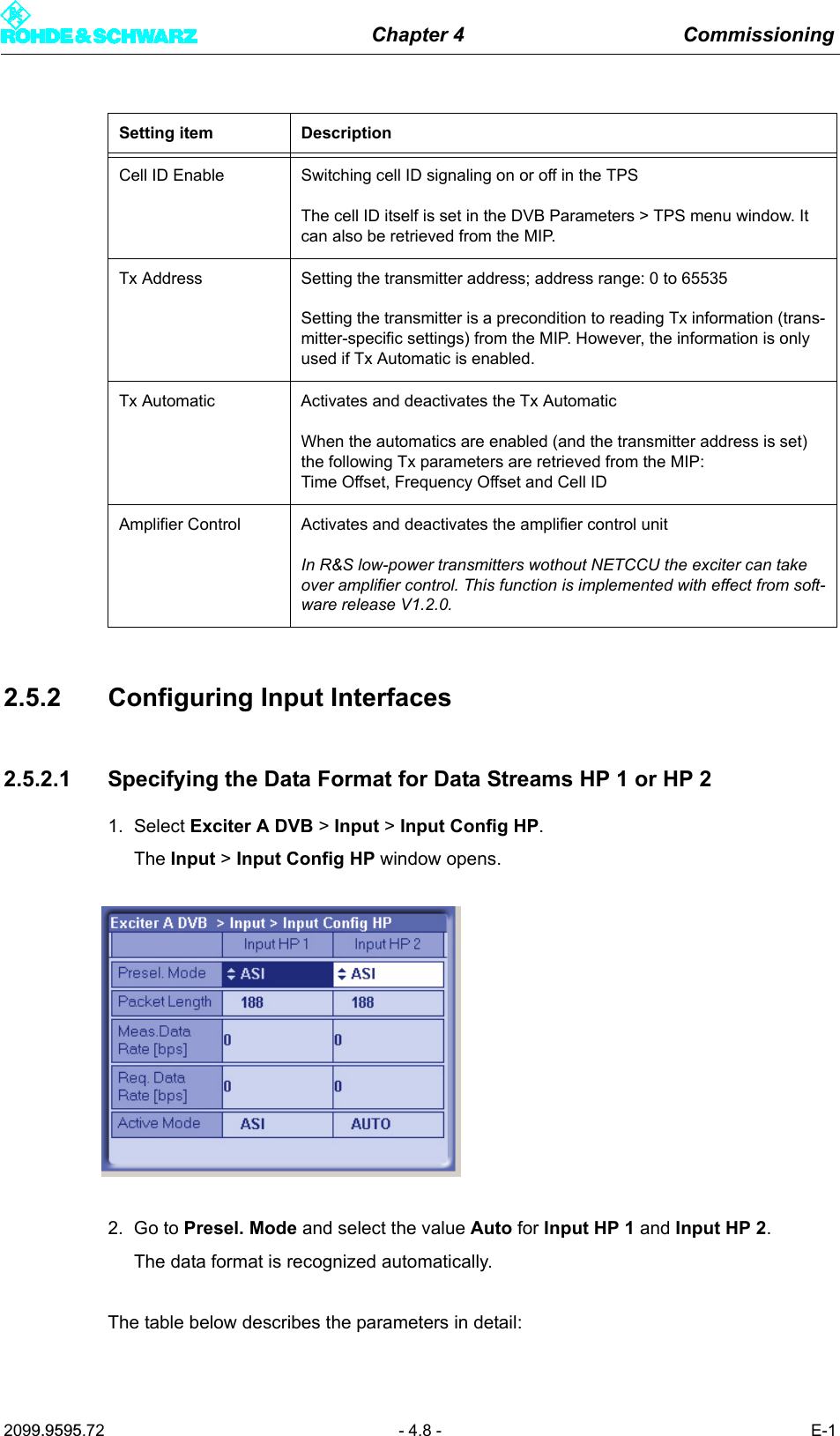
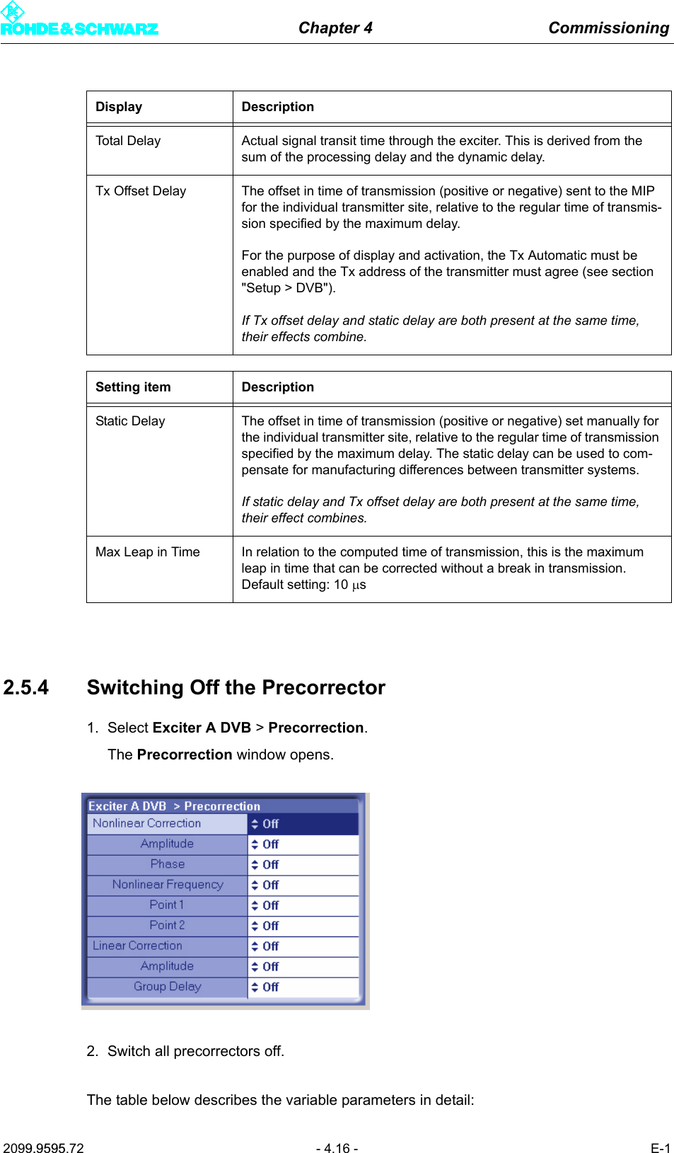
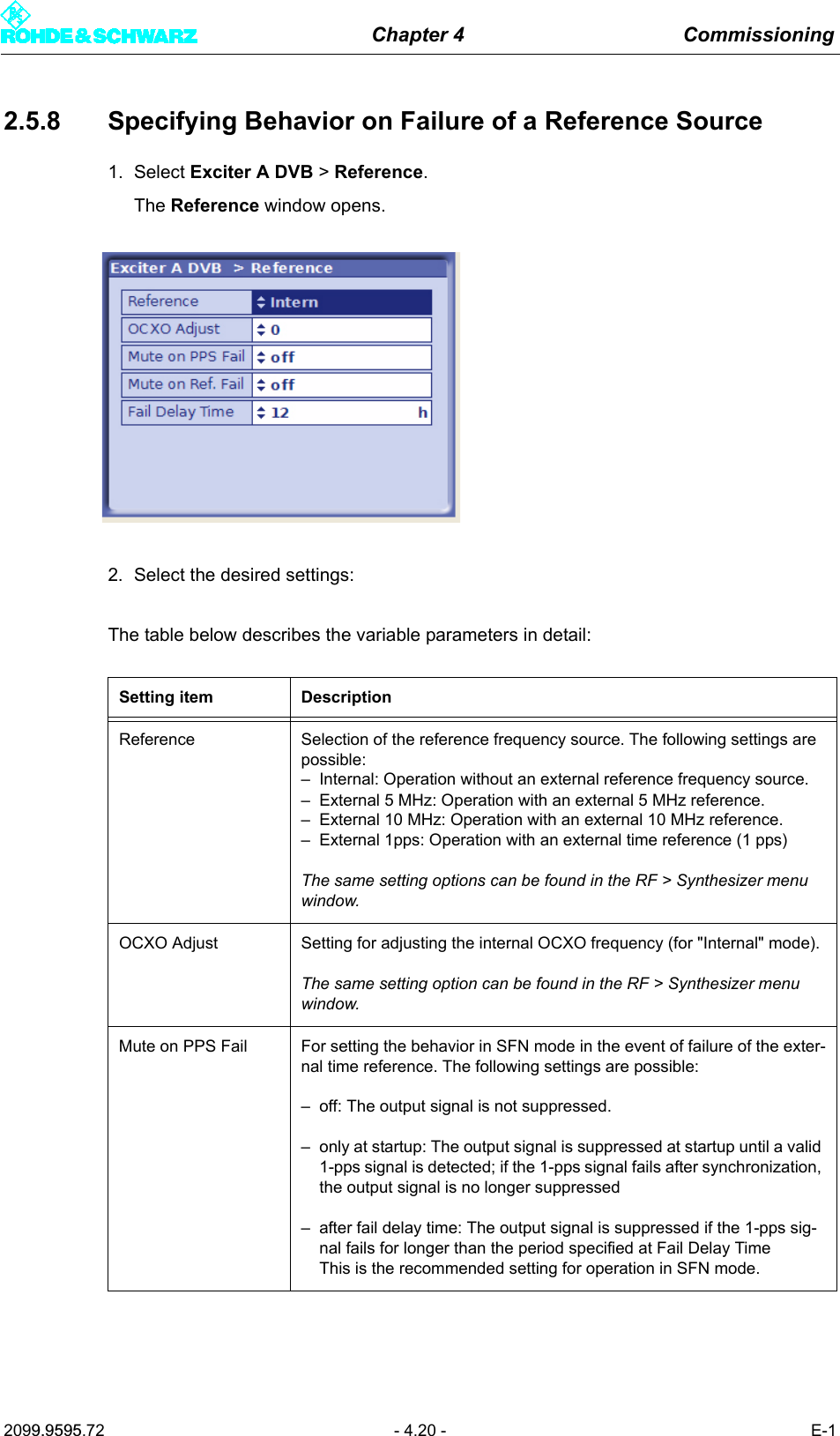
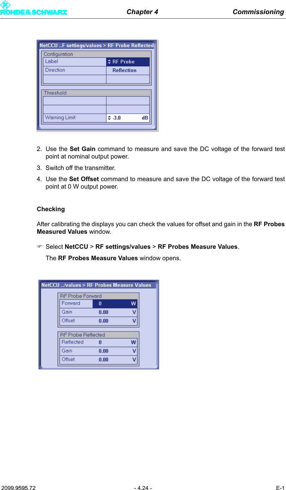
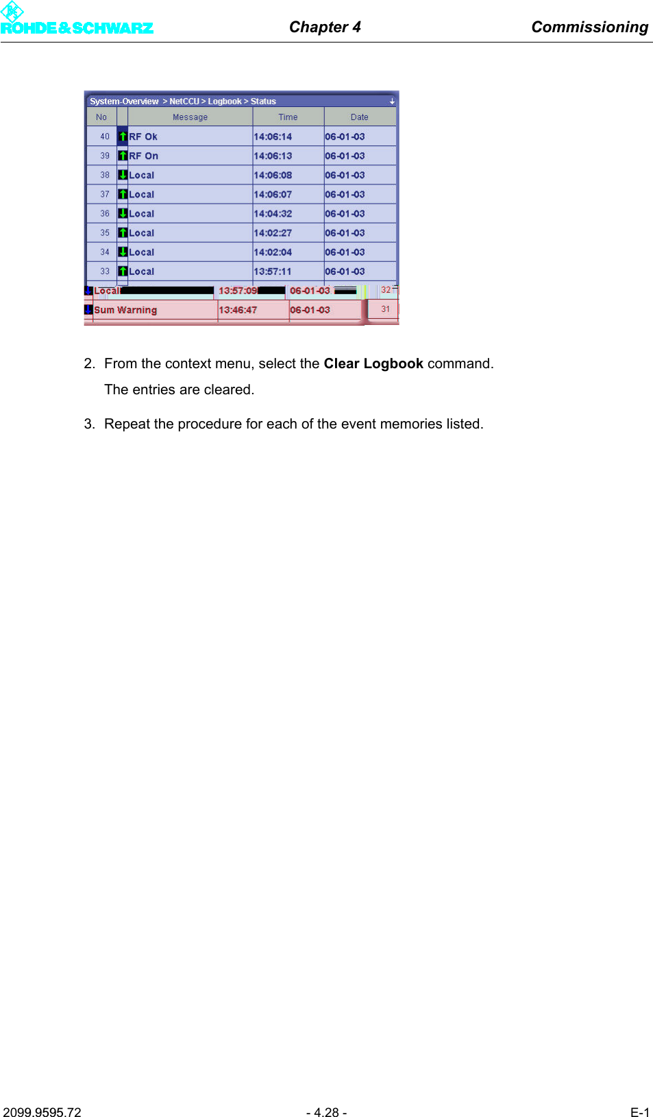
![Chapter 4 Commissioning2099.9595.72 - 4.14 - E-1Display/setting itemDescription of theactive or manually set TPS parametersBandwidth Signal bandwidthDisplay/setting: 5, 6, 7 or 8 MHzFFT Length IFFT lengthDisplay/setting: 2k or 8k; also 4k in the case of DVB-HGuard Interval Guard intervalDisplay/setting: 1/4, 1/8, 1/16 or 1/32Constellation Modulation modeDisplay/setting: QPSK, 16QAM or 64QAMIn the case of hierarchical coding the value refers to the sum of the HP and LP stream constellation points; possible values are therefore: 16QAM or 64QAMAlpha Hierarchy parameter αDisplay/setting:– No Hier: Non-hierarchical coding– 1 H: Hierarchical coding with α = 1– 2 H: Hierarchical coding with α = 2– 3 H: Hierarchical coding with α = 31 H, 2 H or 3 H activates the hierarchical coding mode. However, this is only possible if Constellation is set to 16QAM or 64QAM.Cell ID Cell IDDisplay/setting: 0x0000 to 0xFFFFThe Cell ID can only be retrieved from the MIP if the Tx Automatic is activated and the Tx address is correctly set (see section "Setup > DVB").For the purpose of signaling in the output signal (TPS), Parameter Cell ID Enable must also be activated (see section "Setup > DVB").Interleaver InterleaverDisplay/setting:– nat: Default setting ("native") with normal function for DVB-T– in depth: 8k interleaving for DVB-H at IFFT lengths of 2k and 4k for improved transmission reliability (DVB-H parameter)Code Rate [HP/LP] Internal code rate (separate for HP and LP stream)Display/setting: 1/2, 2/3, 3/4, 5/6 or 6/7Time Slicing [HP/LP] Time slicing flag (DVB-H parameter)Display/setting separate for HP and LP stream:– OFF: Default setting; no signaling via flag– ON: A flag is set in the broadcast DVB signal. This flag informs the receiver that at least one service in the DVB-H data stream uses time slicing.](https://usermanual.wiki/Acrodyne/NW8201E.USers-Manual-Part-12/User-Guide-864568-Page-18.png)
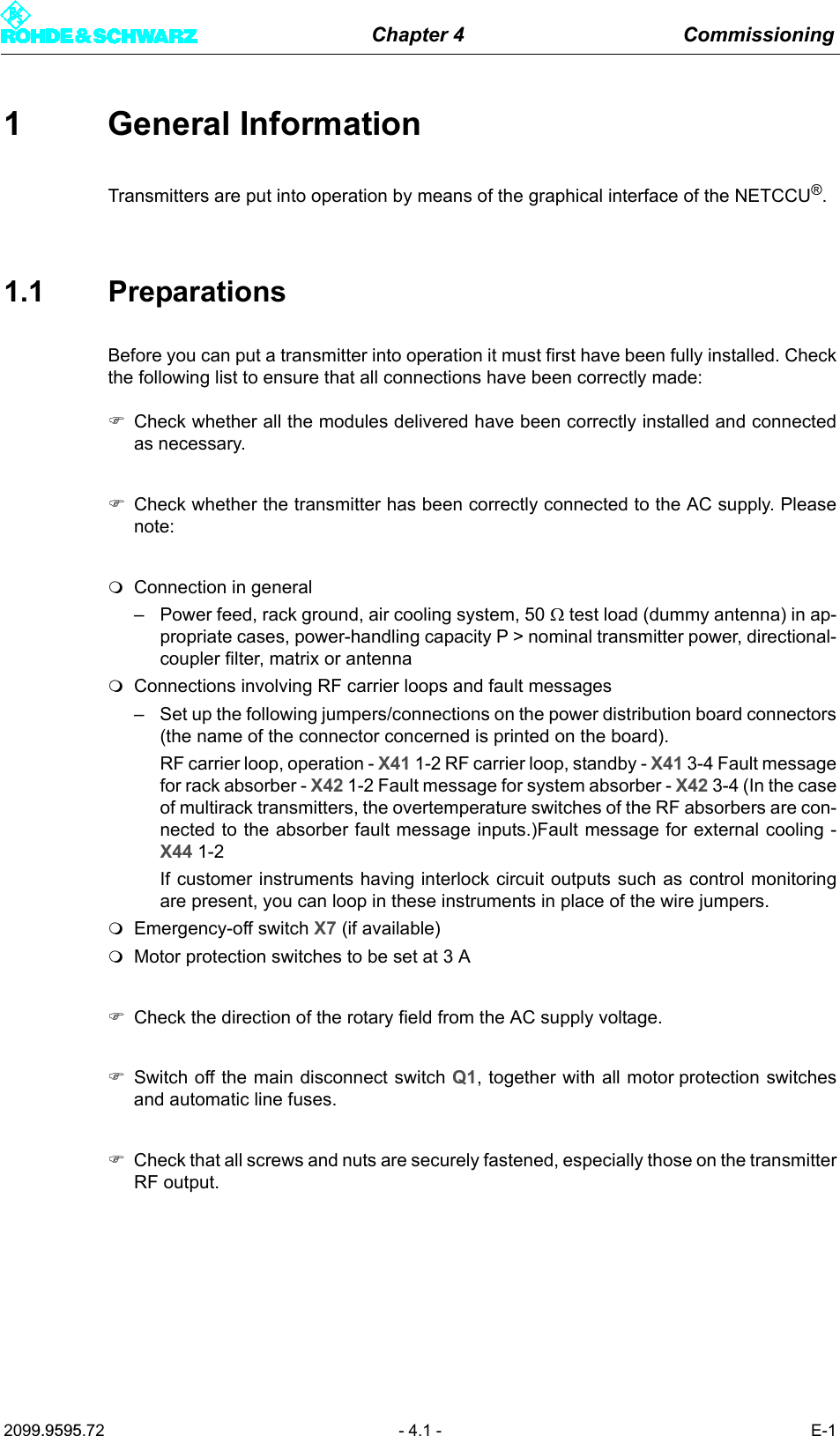
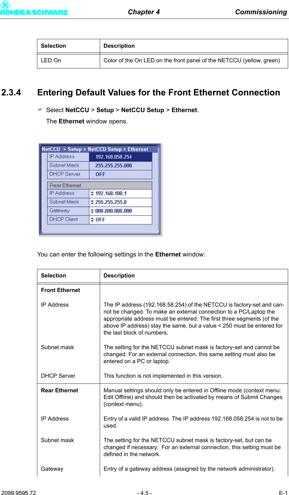
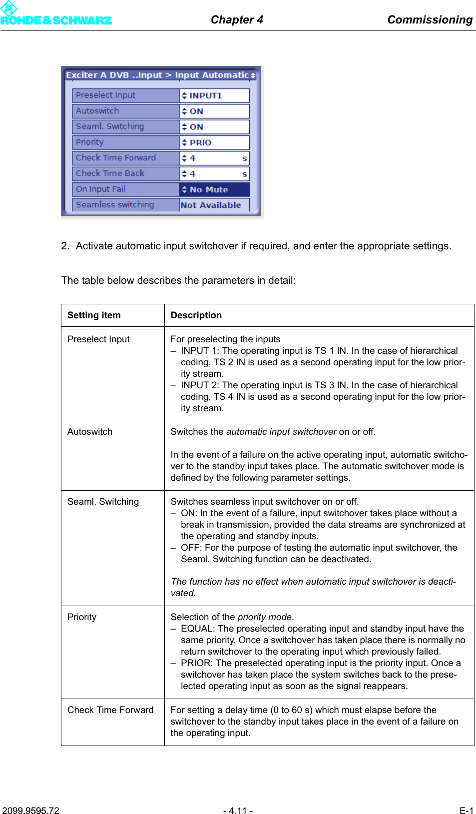
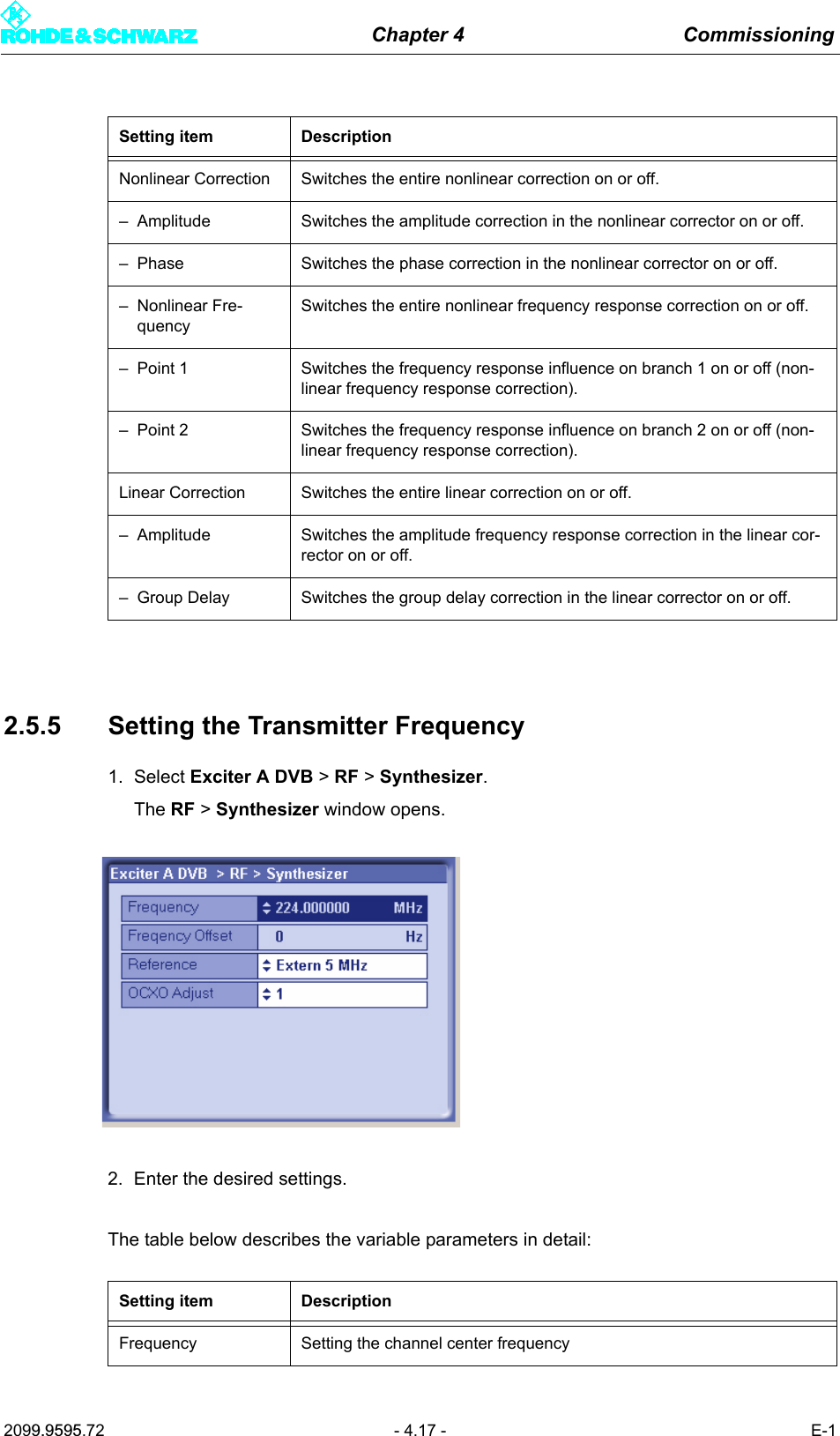
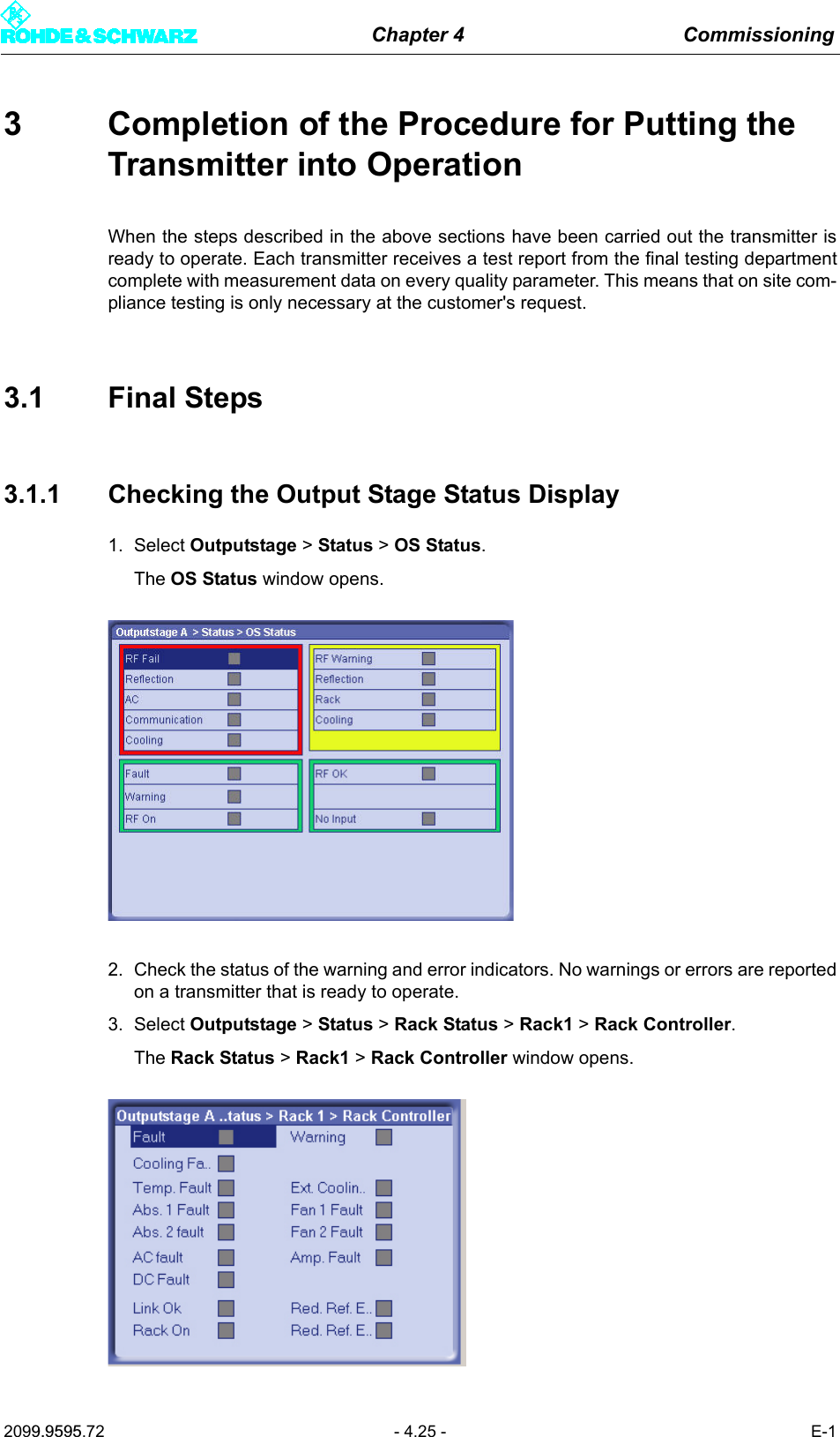
![Chapter 4 Commissioning2099.9595.72 - 4.15 - E-12.5.3.3 Checking Delays at SFN Delay - SFN Mode Only1. Select Exciter A DVB > DVB Parameters > SFN Delay.The DVB Parameters > TPS > SFN Delay window opens.2. If necessary, enter a static delay and check whether the dynamic delay is in the range0 to 1second (if not the single-frequency condition is violated).The table below describes the variable parameters in detail:MPE FEC [HP/LP] MPE FEC flag (DVB-H parameter)Display/setting separate for HP and LP stream:– OFF: Default setting; no signaling via flag– ON: This flag informs the receiver that at least one service in the DVB-H data stream uses forward error correction for MPE (multipro-tocol encapsulation).Req. Data Rate[HP/LP]Display showing the required data rate:cf. section "Input > Input Config HP"Display DescriptionMaximum Delay Period of time between the signal leaving the play-out center (MIP inserter) and its regular transmission at the transmitting antenna. This delay is set in the MIP inserter and serves as a basis for all the transmit-ters in the SFN.Network Delay Signal propagation time between the play-out center (MIP inserter) and the exciter input. This delay depends on the transmission path used.Processing Delay Minimum signal transit time through the exciter. This delay depends on the DVB transmission parameters.Dynamic Delay Period of time by which signal processing is artificially delayed so that the desired time of transmission is obtained.Display/setting itemDescription of theactive or manually set TPS parameters](https://usermanual.wiki/Acrodyne/NW8201E.USers-Manual-Part-12/User-Guide-864568-Page-19.png)
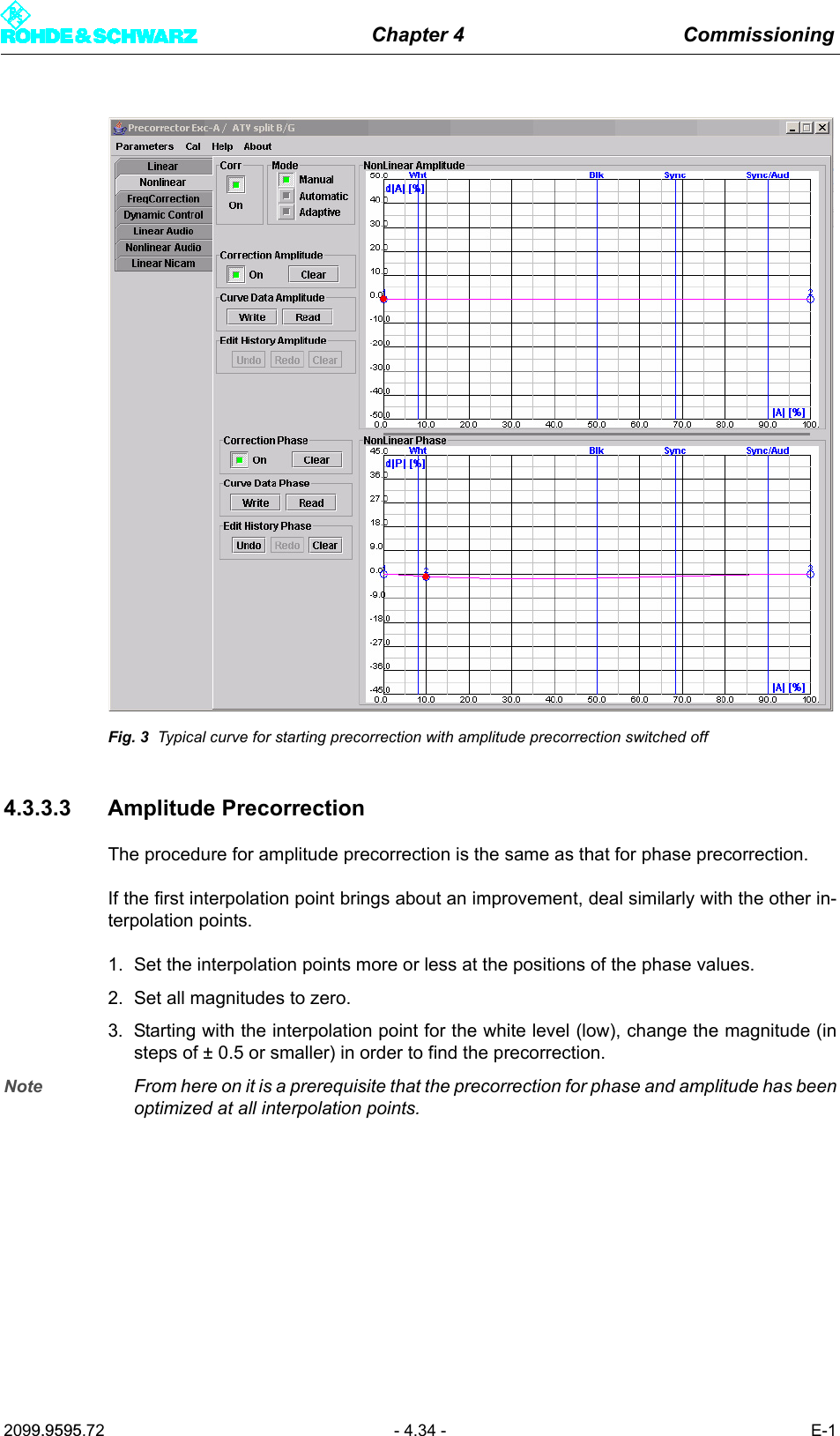
![Chapter 4 Commissioning2099.9595.72 - 4.29 - E-14 PrecorrectionThis section describes the non-linear precorrection sequence in manual mode.4.1 Functions of the Non-Linear Precorrector4.1.1 GeneralIn the basic version, the graphical user interface of the non-linear precorrector for DTV andvideo signals consists of the Nonlinear control panel and the FreqCorrection control pan-el. In the case of ATV split, two further control panels are provided: Dynamic Control forthe video precorrector and Nonlinear Audio for the audio signal. In combined mode an au-dio phase precorrector is also provided for audio.4.1.2 Linear Basic PrecorrectionThe basic functions of the non-linear precorrector can be accessed via the Nonlinear andNonlinear Audio control panels. Additional functions can be performed in the other controlpanels.Every non-linear precorrector consists of an amplitude precorrector and a phase precorrec-tor, each independently affecting the phase distortion and amplitude distortion of the samesignal. The setting of the characteristic is displayed in a graphic in which the X axis repre-sents the instantaneous signal amplitude. The figures 0% and 100% stand for no signal am-plitude and maximum amplitude respectively. The Y axis represent the effect and is scaledto ±50 % for amplitude precorrection and ±45° for phase precorrection. 50% means that at100% amplitude the level is increased by 3 dB.Every precorrector has a series of frequency reference points which are used to model thecharacteristic. Frequency reference points can be user-defined, shifted in the X and Y di-rections, be given a fixed or free slope and be deleted. In the X direction a frequency refer-ence point can only be shifted between the two adjacent reference points. The connectionsbetween frequency reference points are computed by means of spline functions.Every characteristic consists of at least two points, one of which must be at 0% and the oth-er at 100%.In the case of amplitude precorrection the first point is at [0%, 0%] and cannot be shifted.The second point is at 100% and can be shifted without restriction in the Y direction. A risingor falling straight line between the two points represents only an amplification or attenuationof the signal and does not create non-linear products.In the case of phase precorrection the first point is at 0% and the second point is at 100%.Both points can be shifted without restriction in the Y direction. A straight line parallel to theamplitude axis creates only a signal phase shift and does not create non-linear products.](https://usermanual.wiki/Acrodyne/NW8201E.USers-Manual-Part-12/User-Guide-864568-Page-33.png)