Acrodyne NW8201E DIGITAL TELEVISION BROADCAST TRANSMITTER User Manual 32 NV8202 26 04 06 01 00
Acrodyne Industries, Inc. DIGITAL TELEVISION BROADCAST TRANSMITTER 32 NV8202 26 04 06 01 00
Acrodyne >
Contents
- 1. Users Manual Part 1
- 2. Users Manual Part 2
- 3. Users Manual Part 3
- 4. Users Manual Part 4
- 5. Users Manual Part 5
- 6. Users Manual Part 6
- 7. Users Manual Part 7
- 8. Users Manual Part 8
- 9. Users Manual Part 9
- 10. Users Manual Part 10
- 11. Users Manual Part 11
- 12. USers Manual Part 12
- 13. Users Manual Part 13
- 14. Users Manual Part 14
- 15. Users Manual Part 15
- 16. Users Manual Part 16
- 17. Users Manual Part 17
- 18. Users Manual Part 18
- 19. Users Manual Part 19
- 20. Users Manual Part 20
Users Manual Part 13
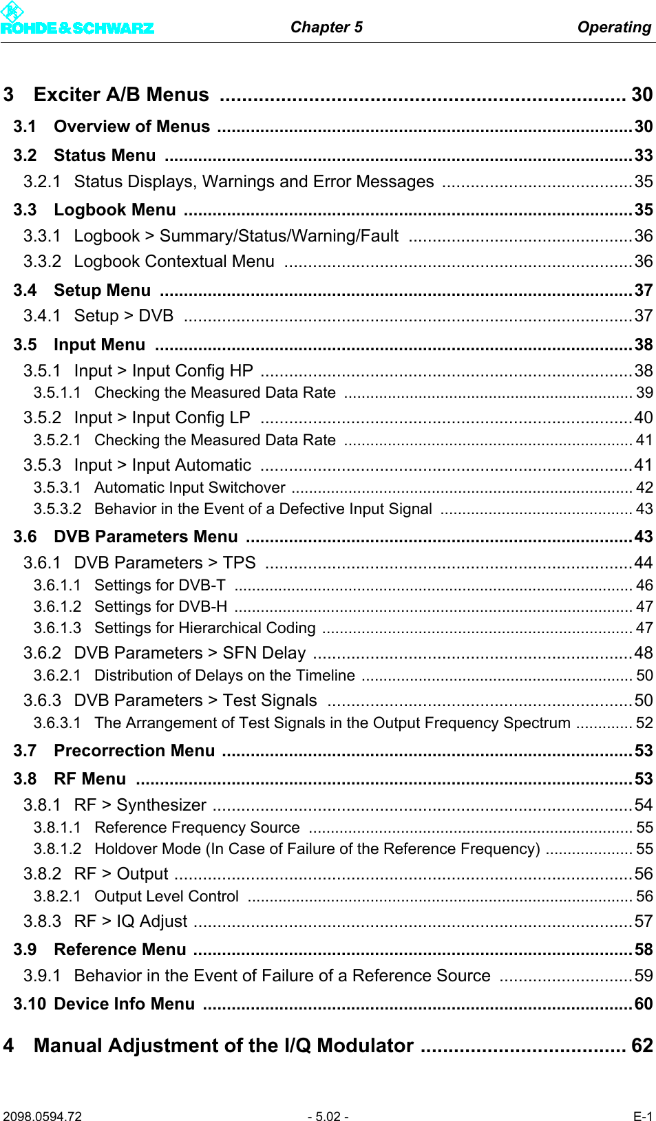
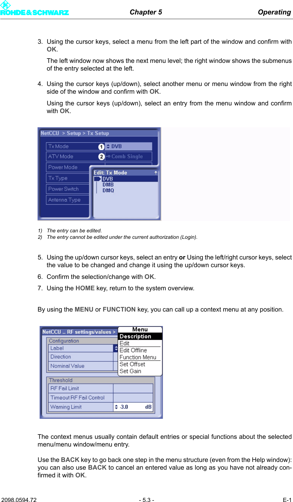
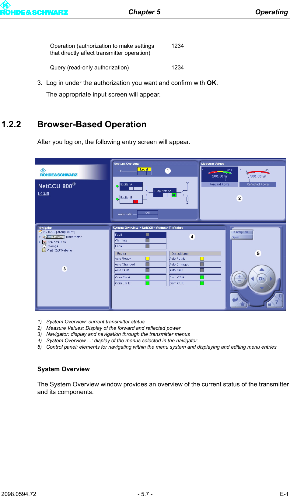
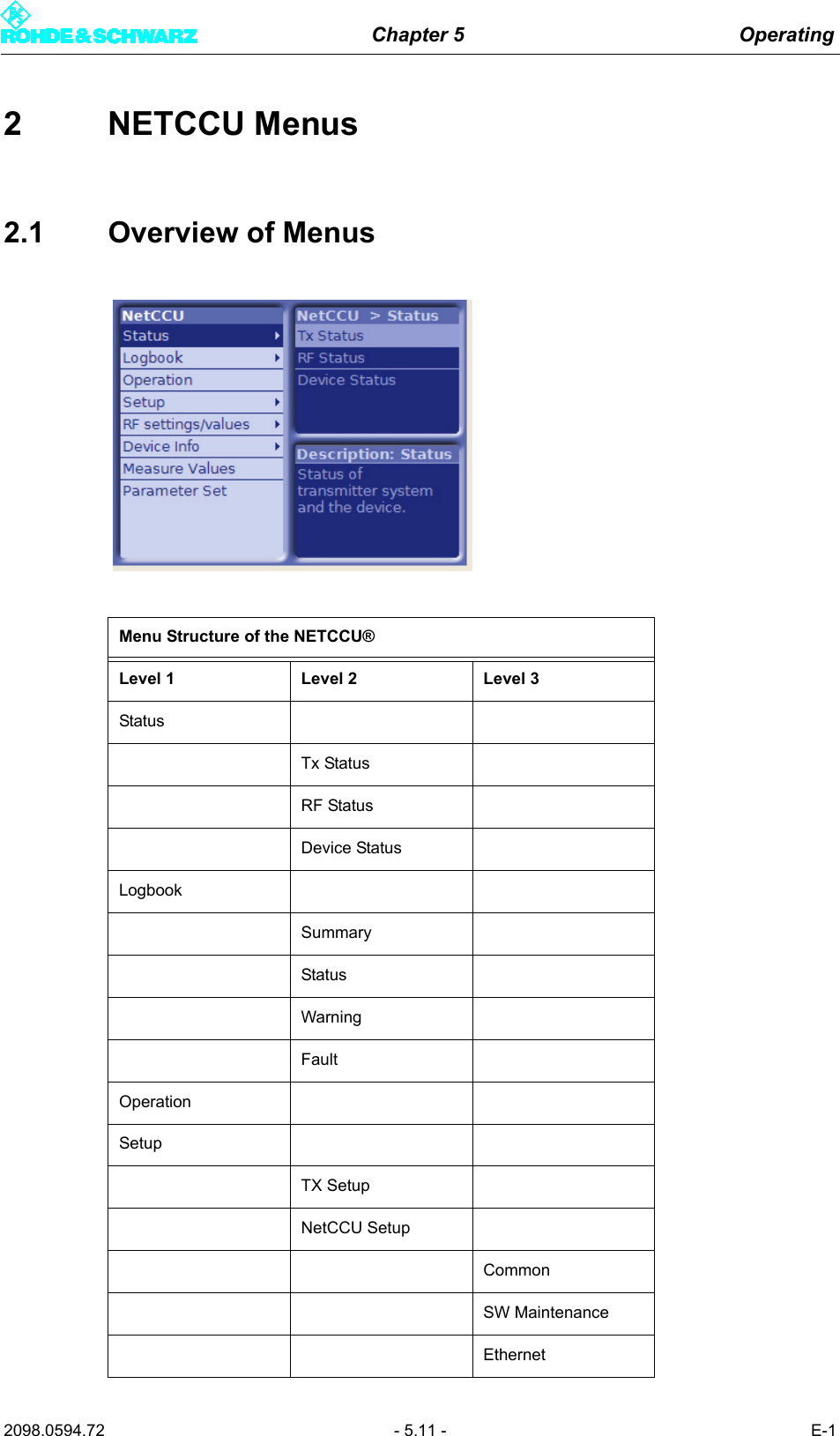
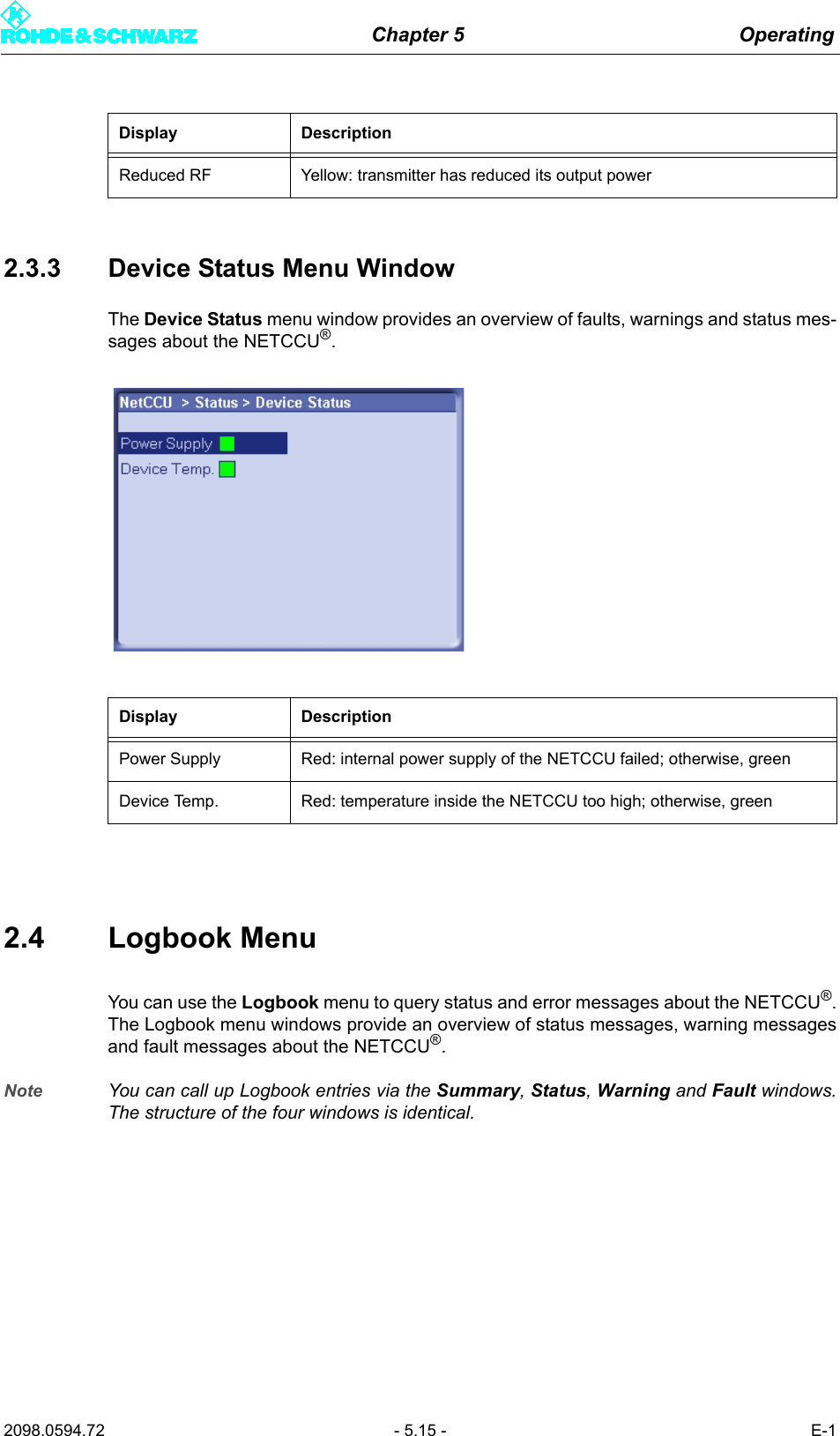
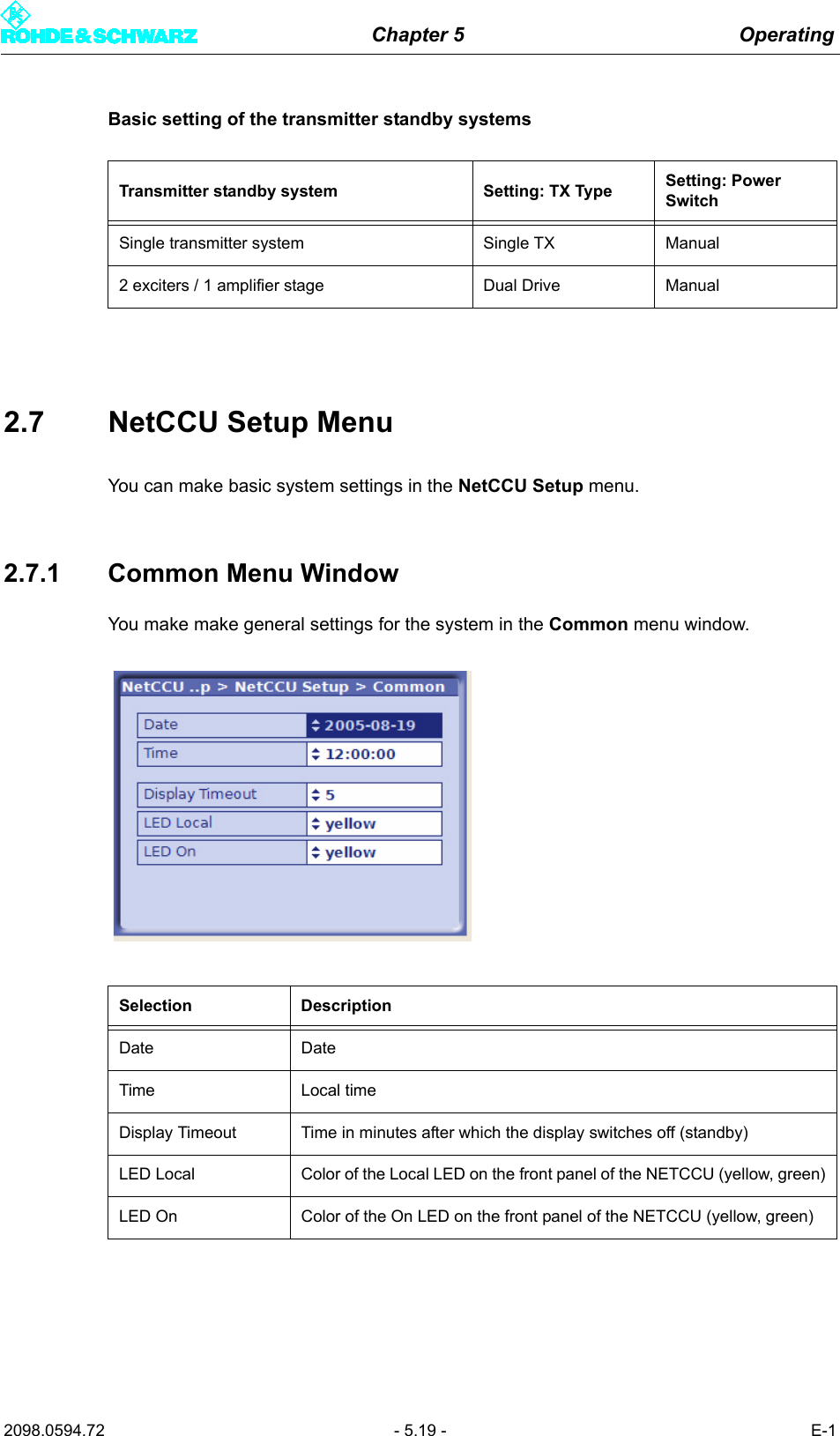
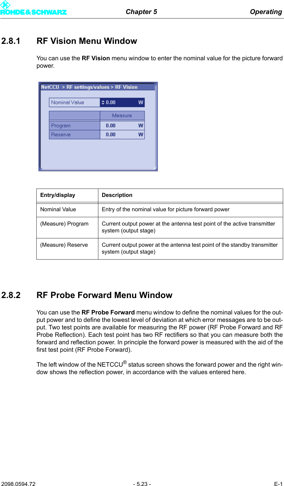
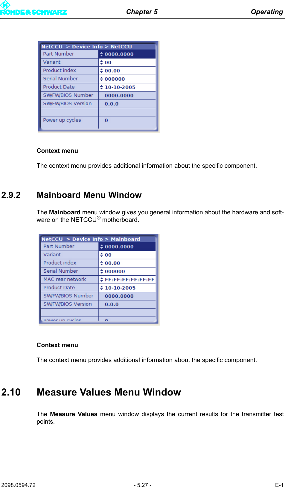
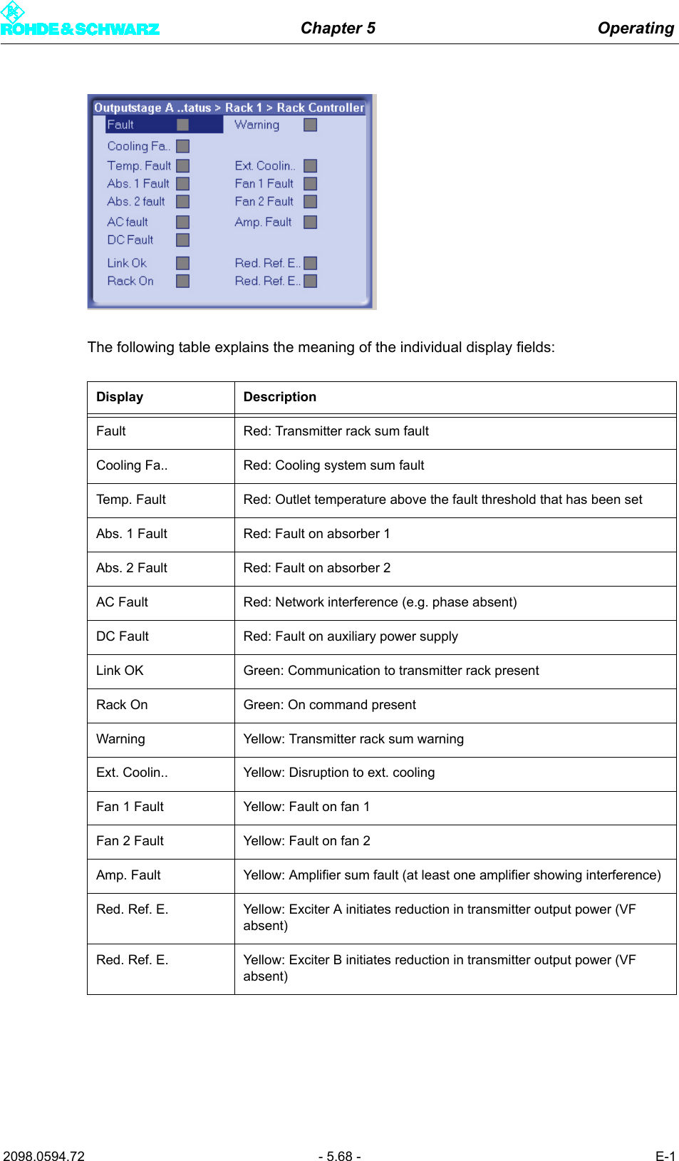
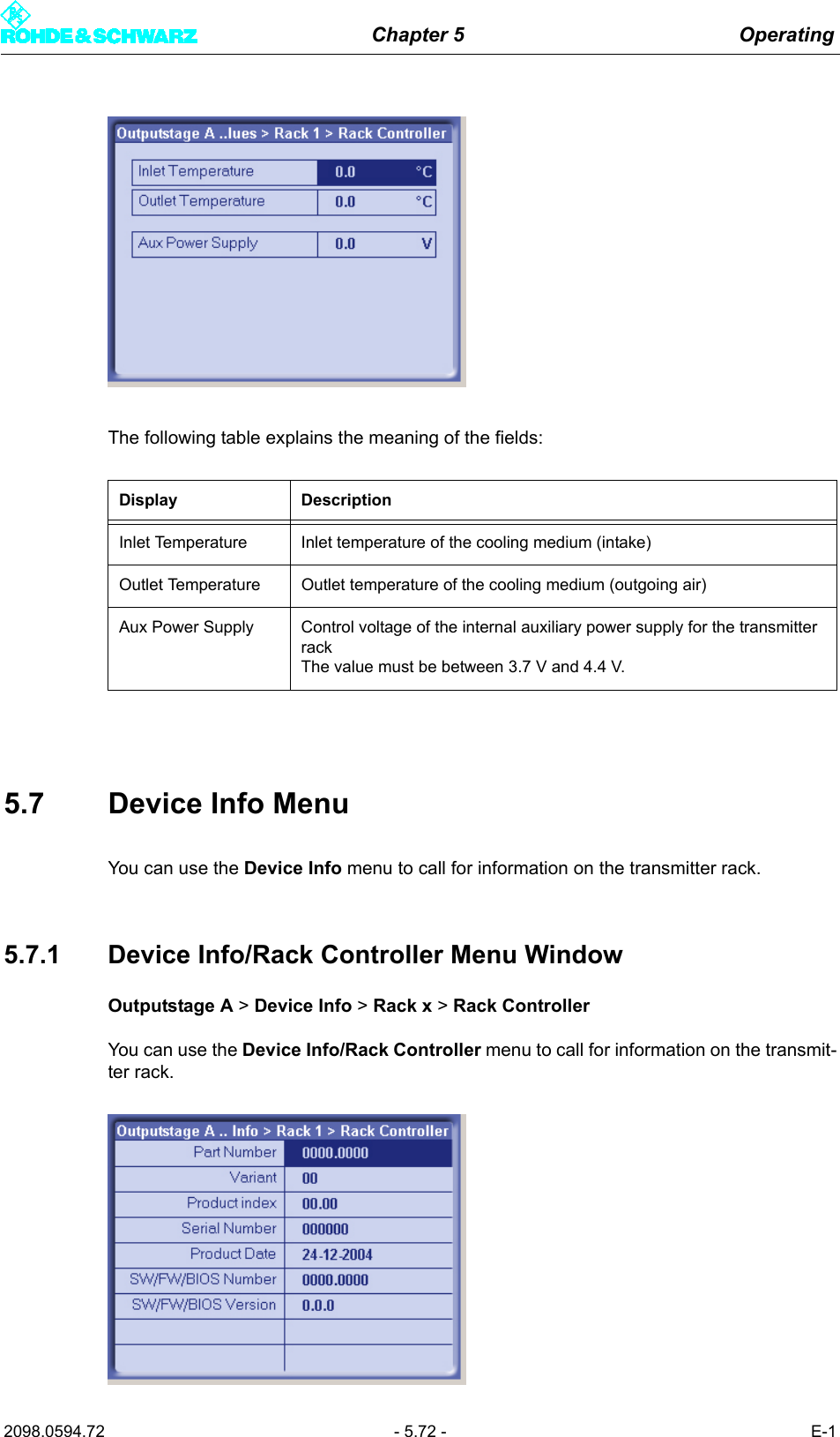
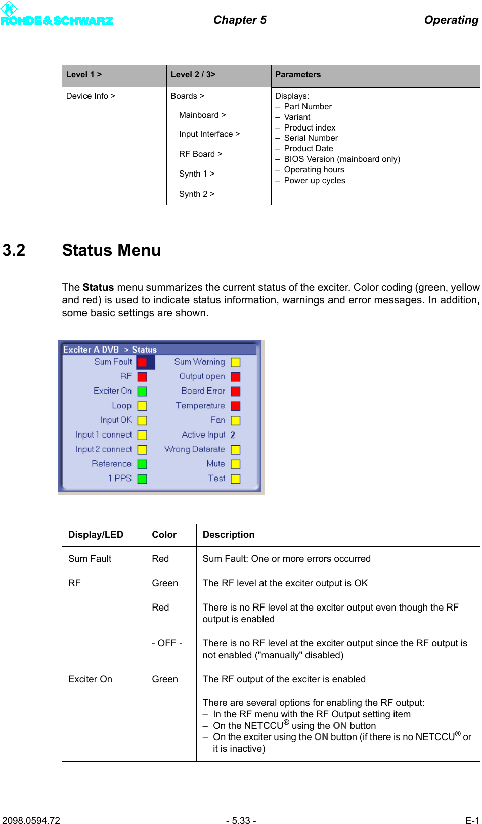
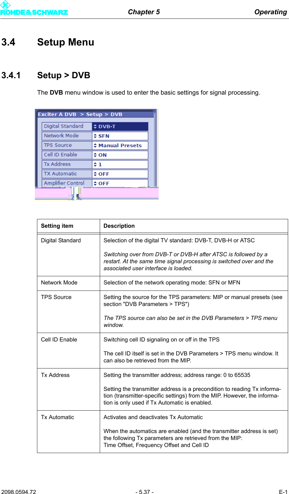
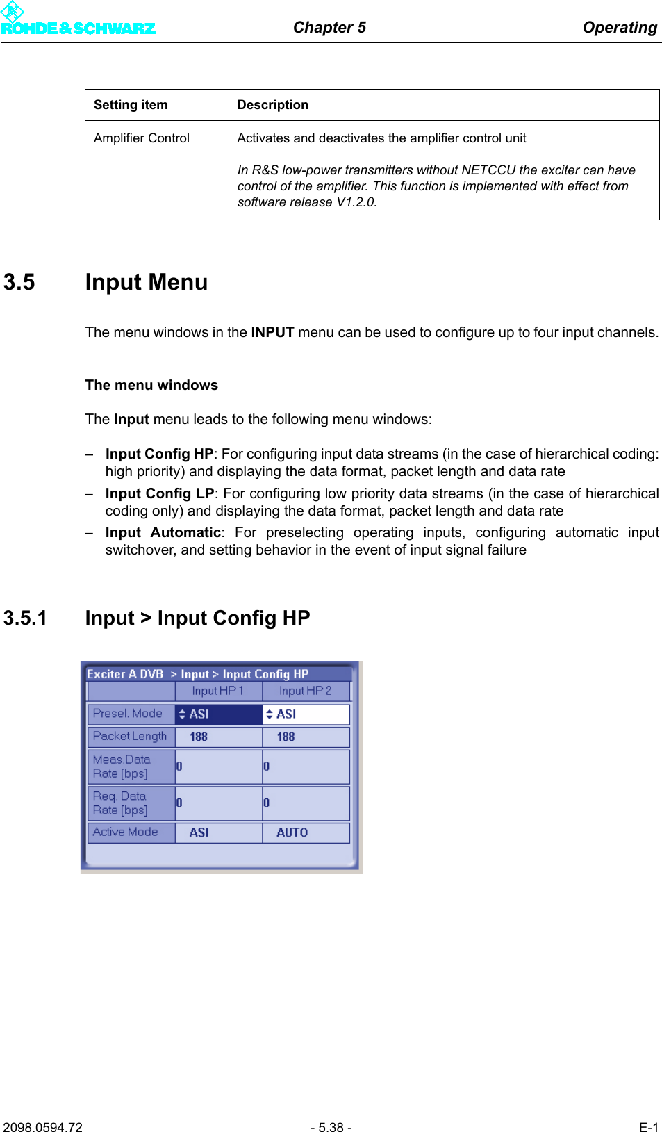
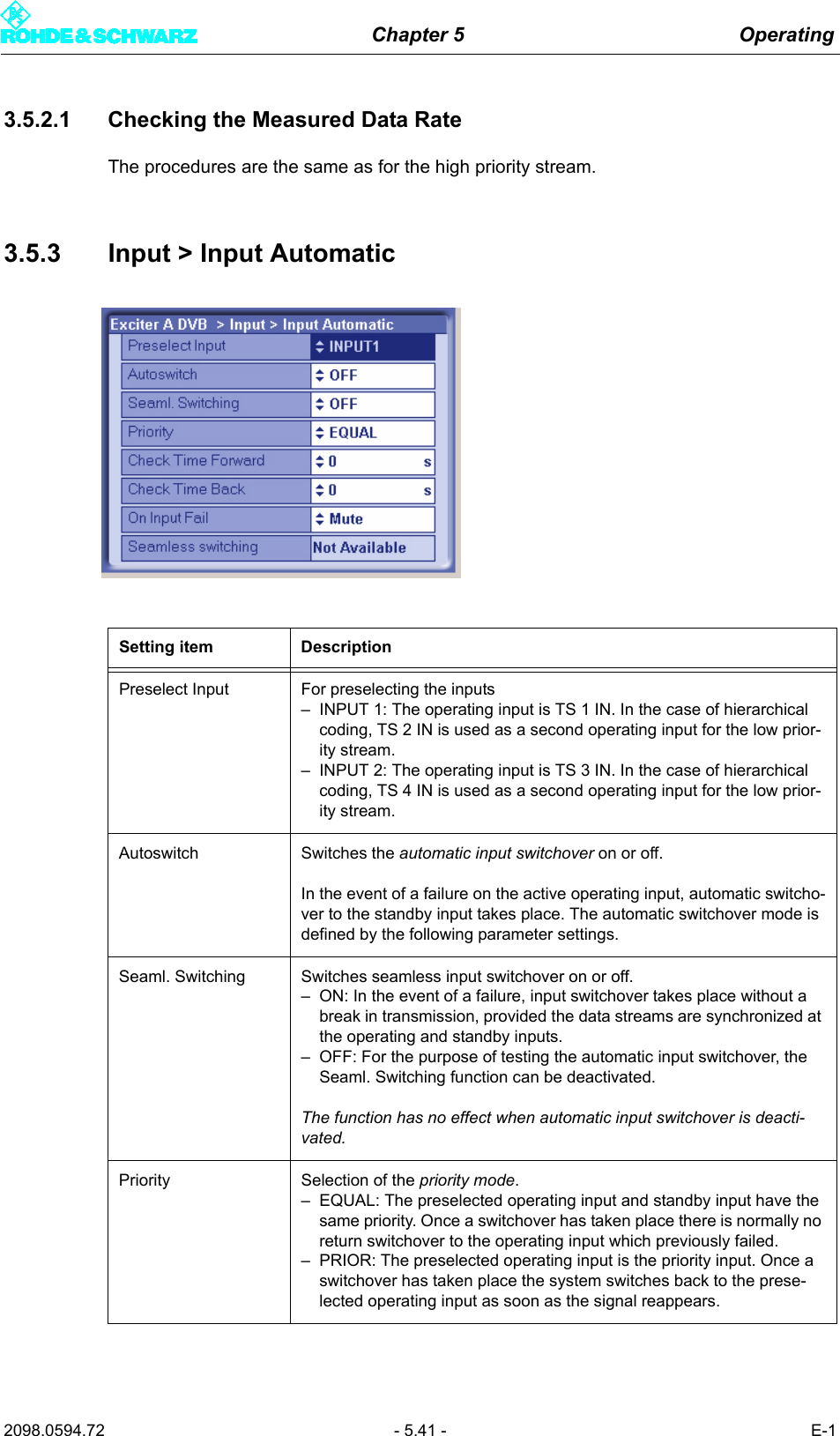
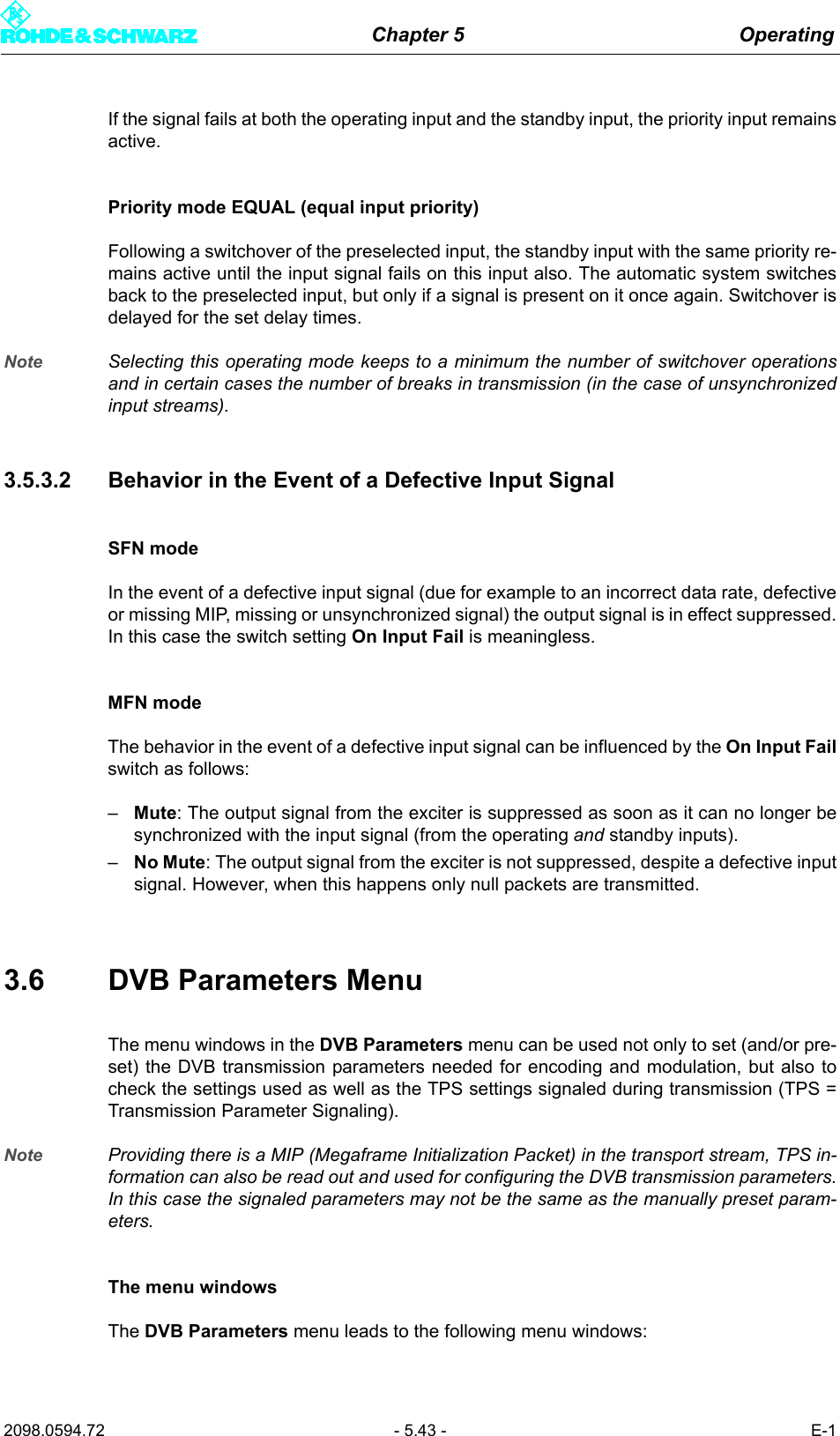
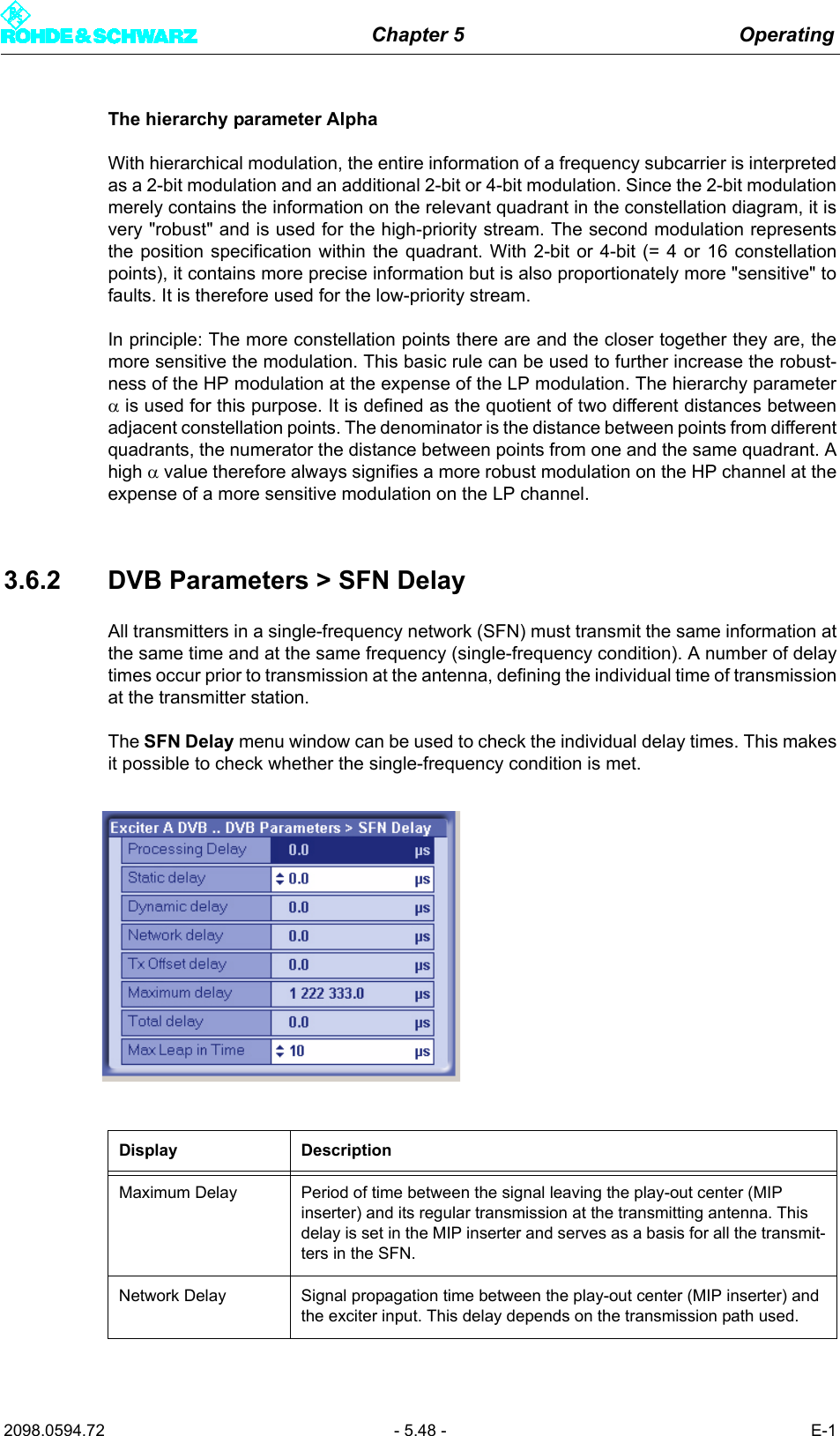
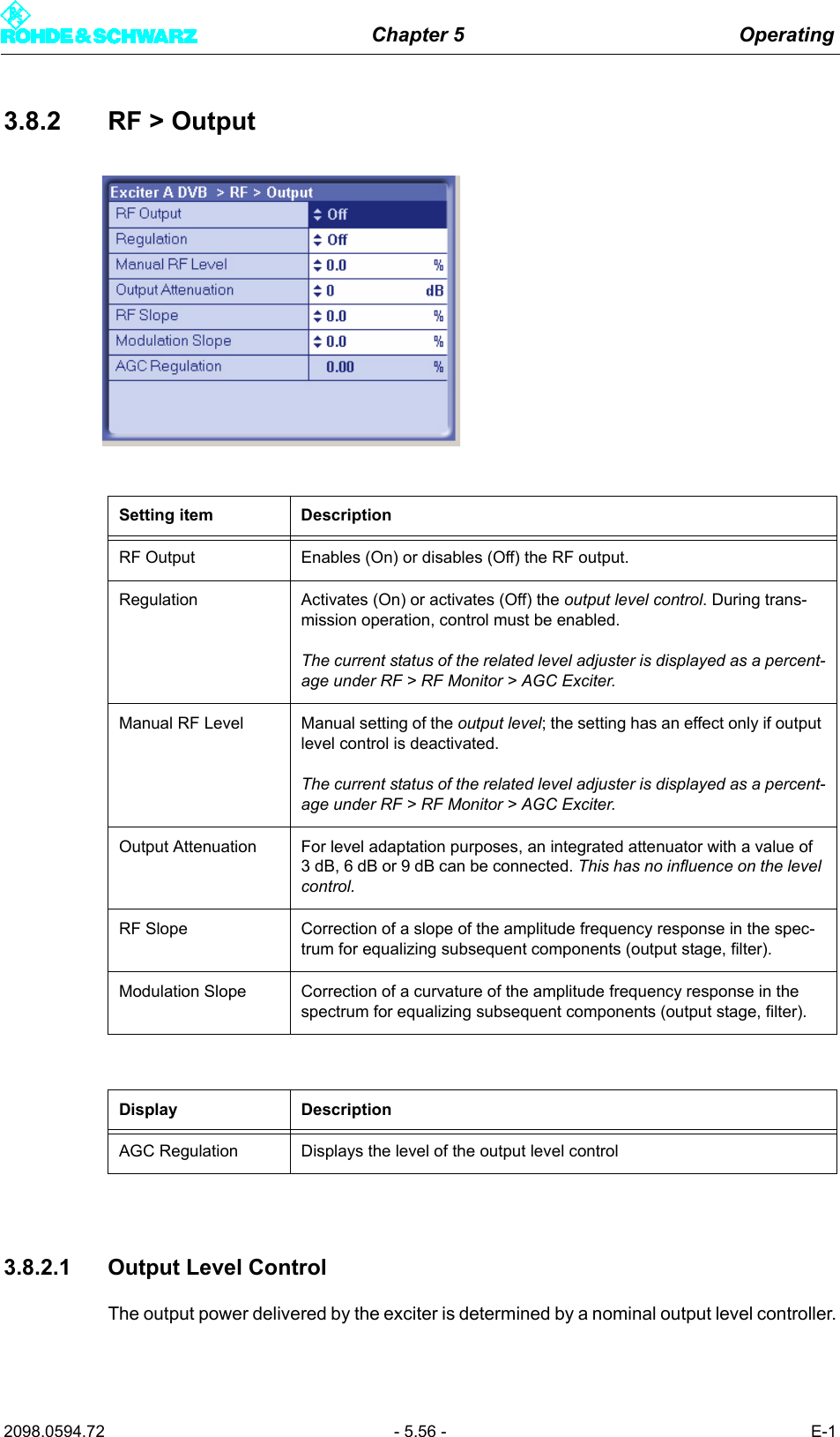
![Chapter 5 Operating2098.0594.72 - 5.31 - E-1Setup > DVB > Setting items:– Digital Standard– Network Mode– TPS Source– Cell ID Enable– TX Address– TX Automatic– Amplifier ControlInput > Input Config HP > Setting items for Input HP 1 or Input HP 2 as appropri-ate:– Presel. ModeDisplays for Input HP 1 or Input HP 2 as appropriate:– Packet Length – Meas. Data Rate [bps]– Req. Data Rate [bps]–Active ModeInput > Input Config LP > Displays for Input LP 1 or Input LP 2 as appropriate:– Presel. ModeDisplays:– Packet Length – Meas. Data Rate [bps]– Req. Data Rate [bps]–Active ModeInput > Input Automatic > Setting items:– Preselect Input–Autoswitch–Seaml. Switching–Priority– Check Time Forward– Check Time Back– On Input FailDisplays:– Seamless switchingDVB Parameters > TPS > Setting item– TPS SourceDisplays: Active / Setting items: Manual:– Bandwidth– FFT Length– Guard Interval– Constellation– Alpha–Cell ID– Interleaver– Code Rate [HP/LP]– Time Slicing [HP/LP]– MPE FEC [HP/LP]Display: Active– Req. Data Rate [HP/LP]DVB Parameters > SFN Delay > Setting items:–Static Delay– Max Leap in TimeDisplays:– Processing Delay– Dynamic Delay– Network Delay– TX Offset Delay– Maximum Delay– Total DelayLevel 1 > Level 2 / 3> Parameters](https://usermanual.wiki/Acrodyne/NW8201E.Users-Manual-Part-13/User-Guide-864578-Page-37.png)
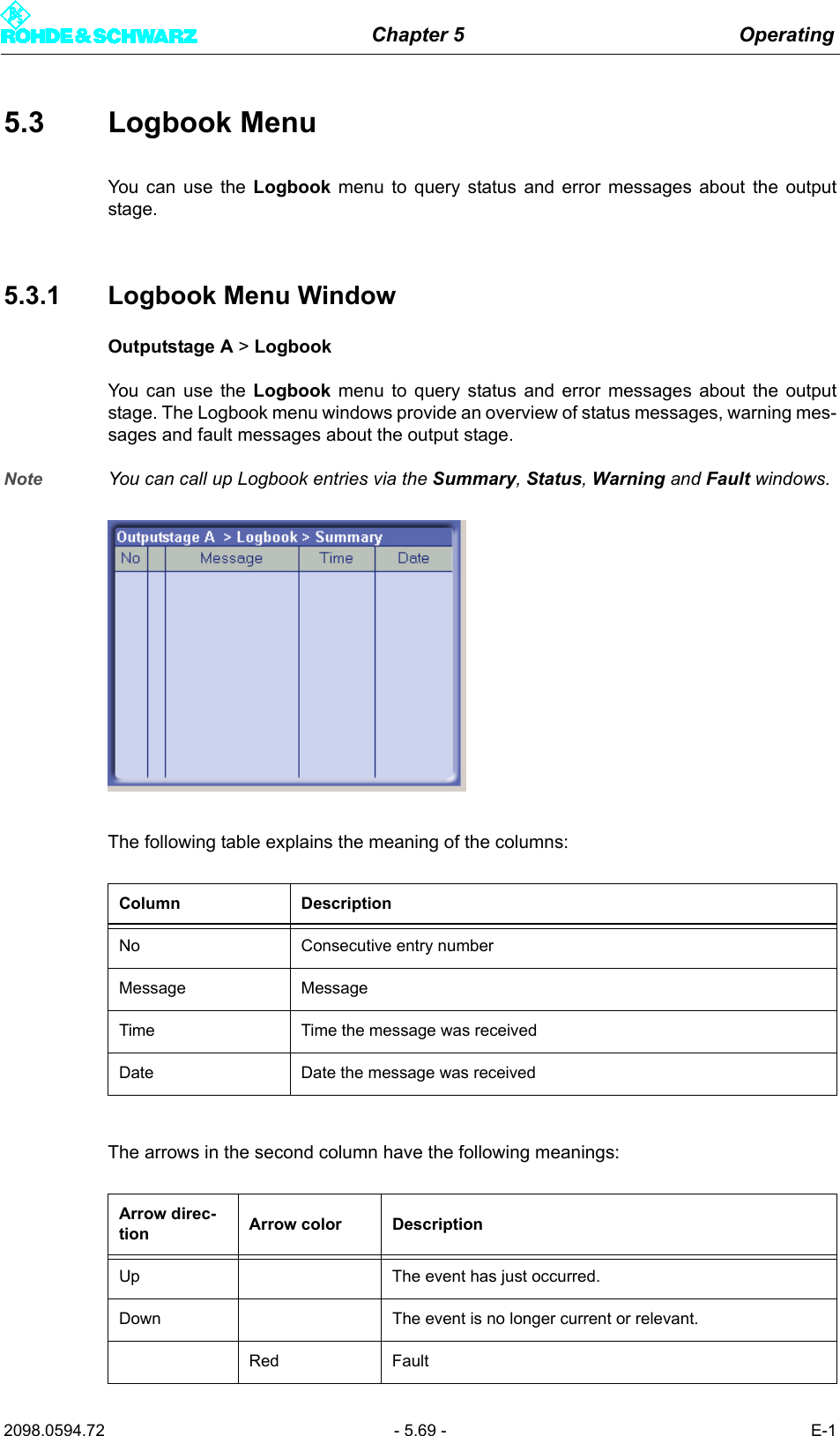
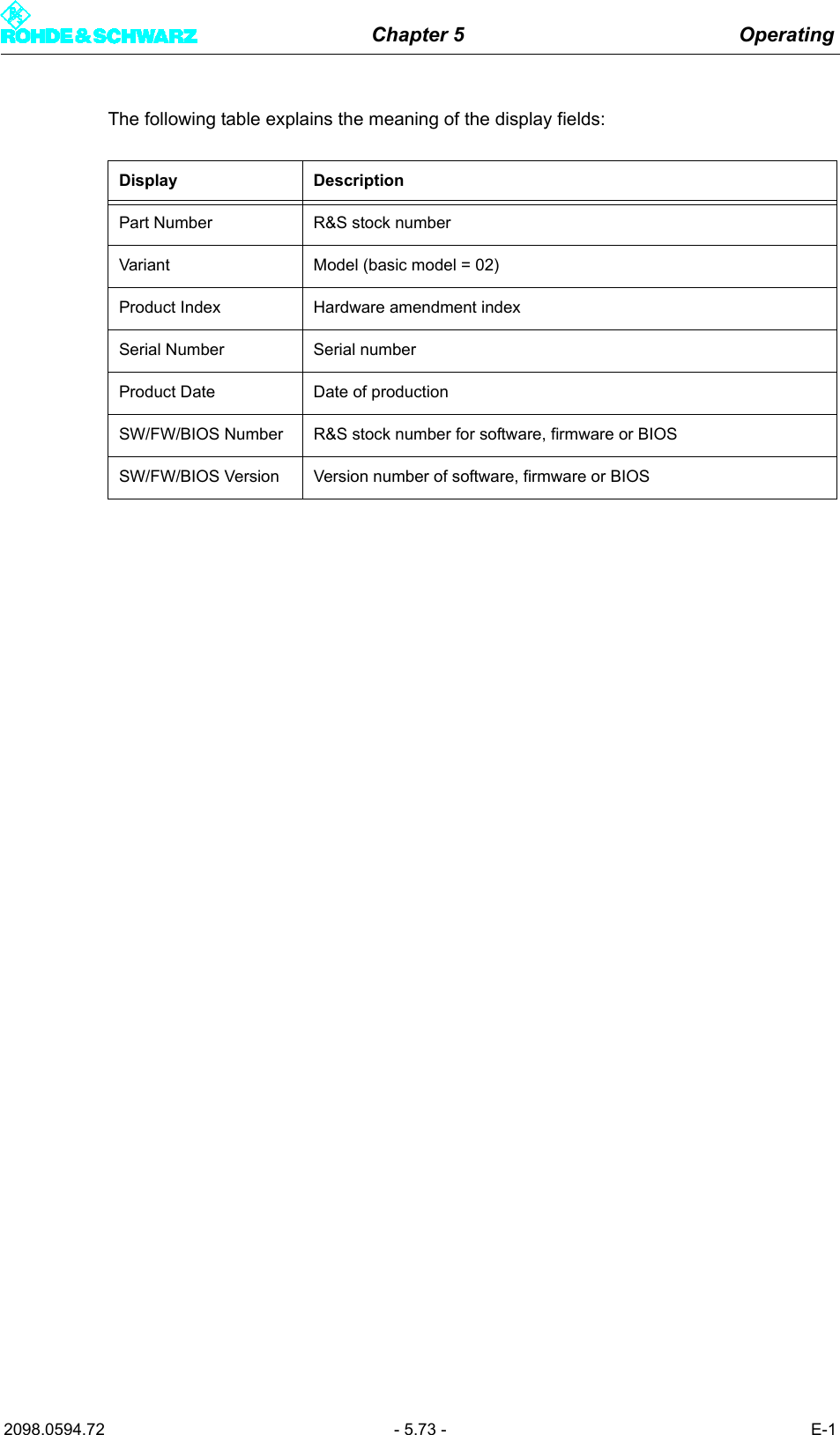
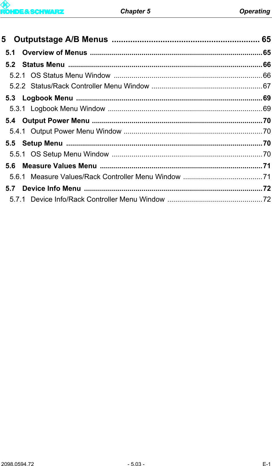
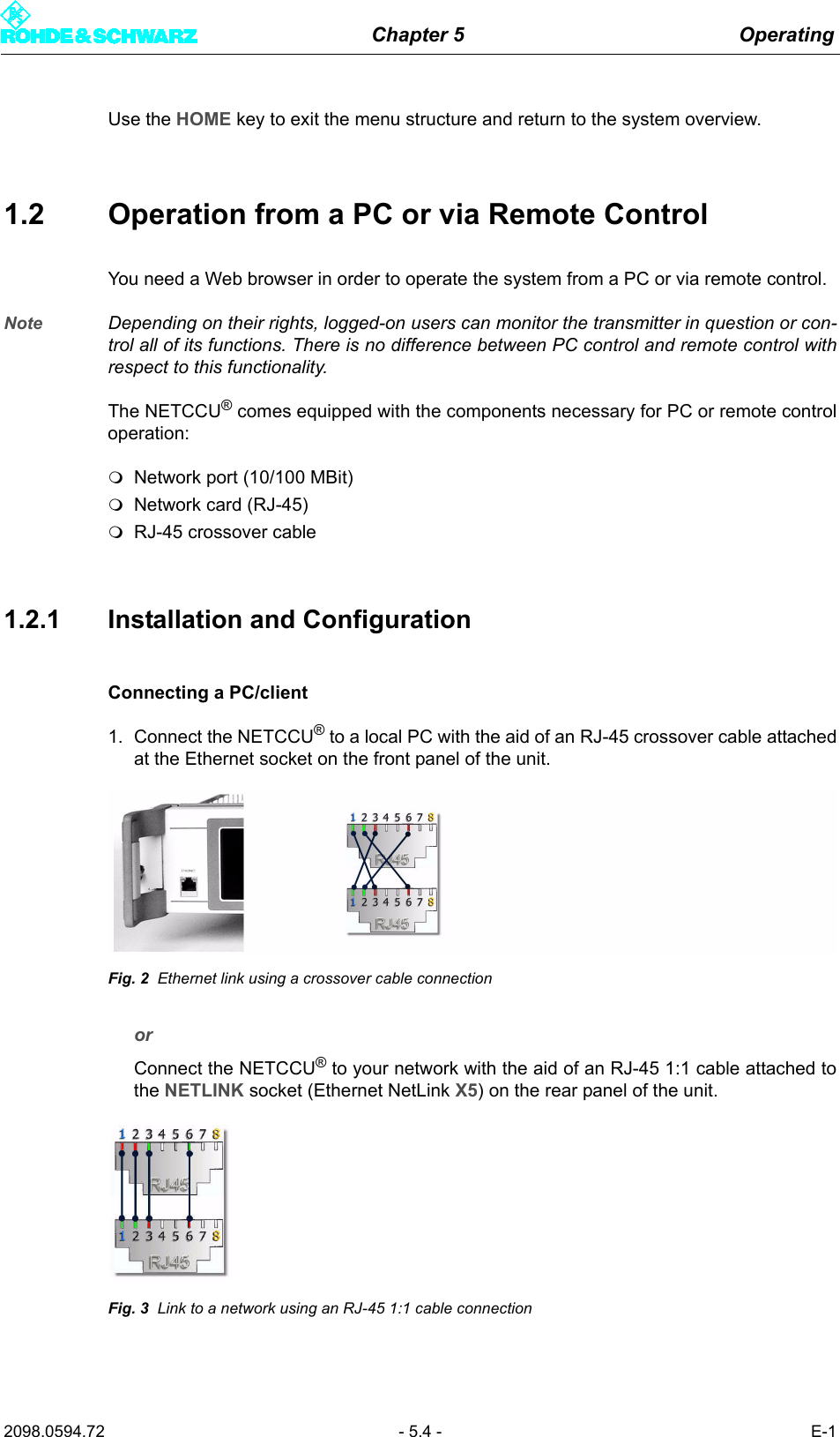
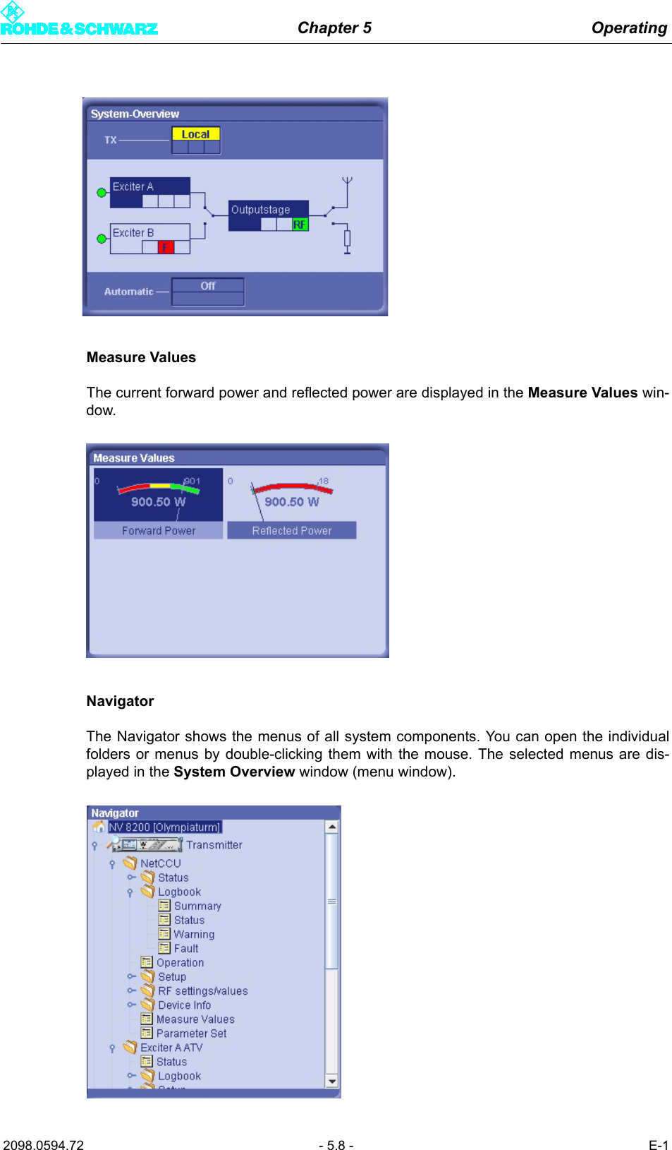
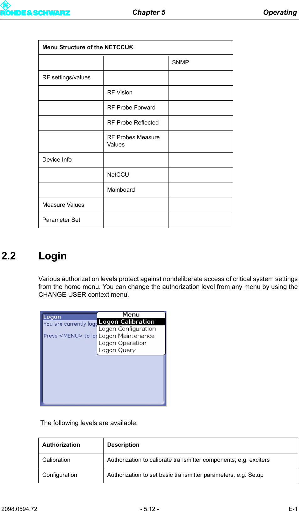
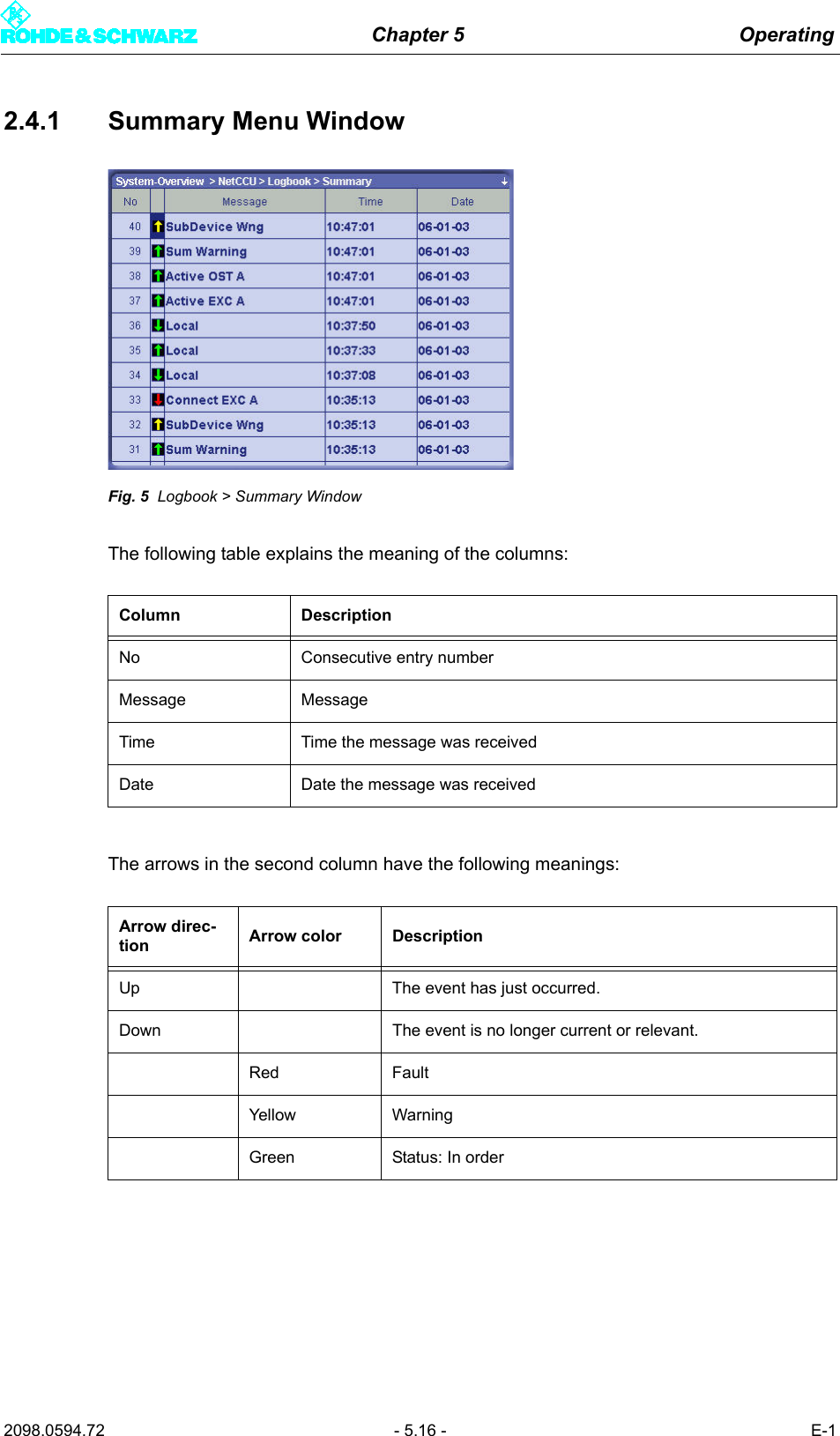
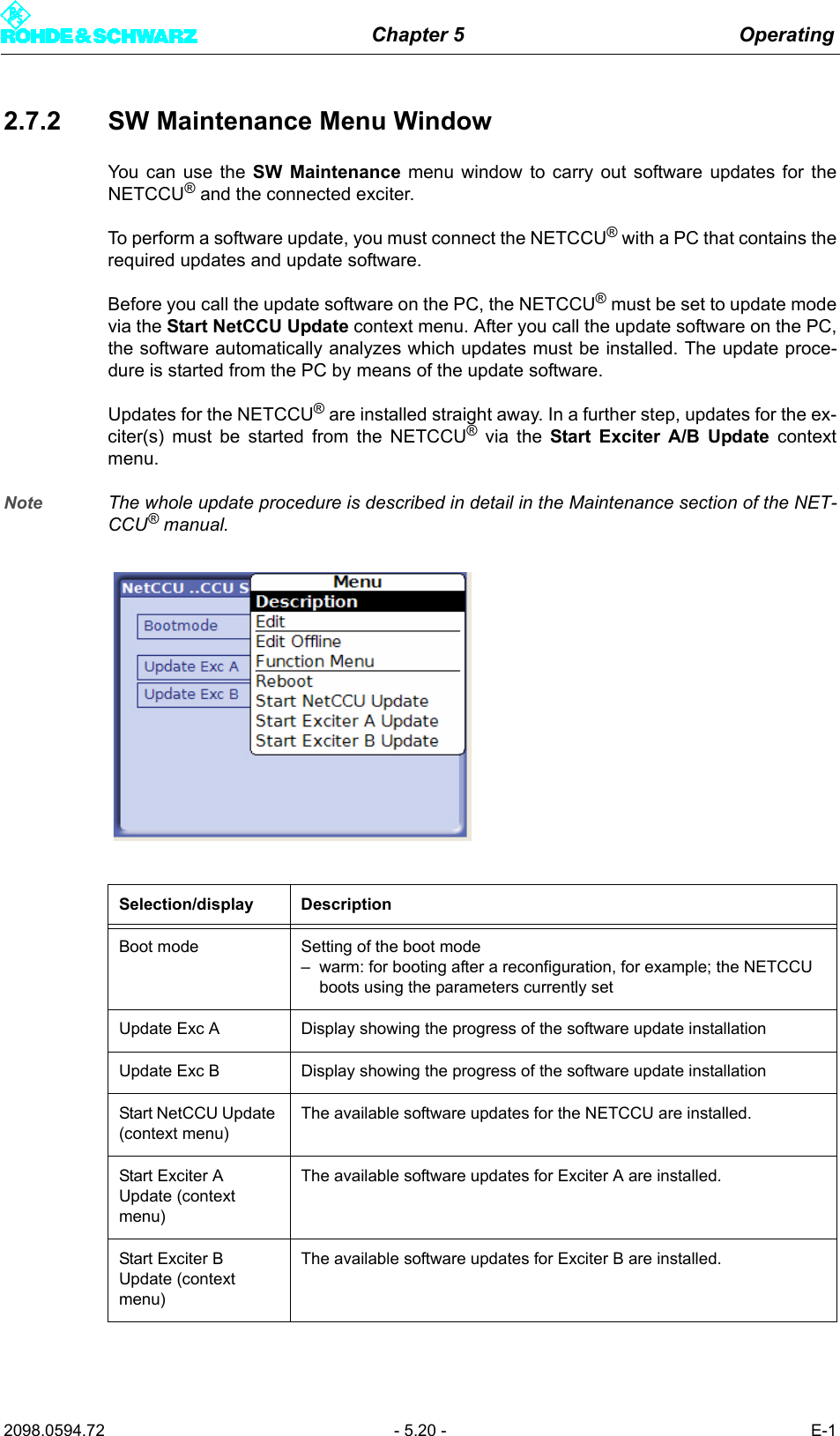
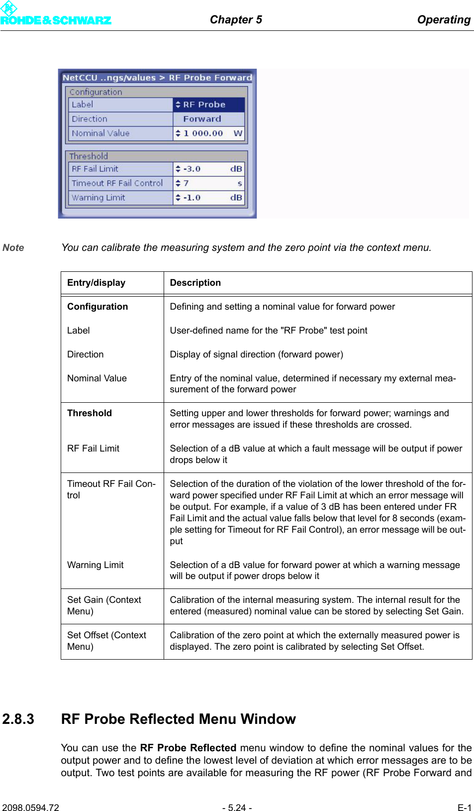
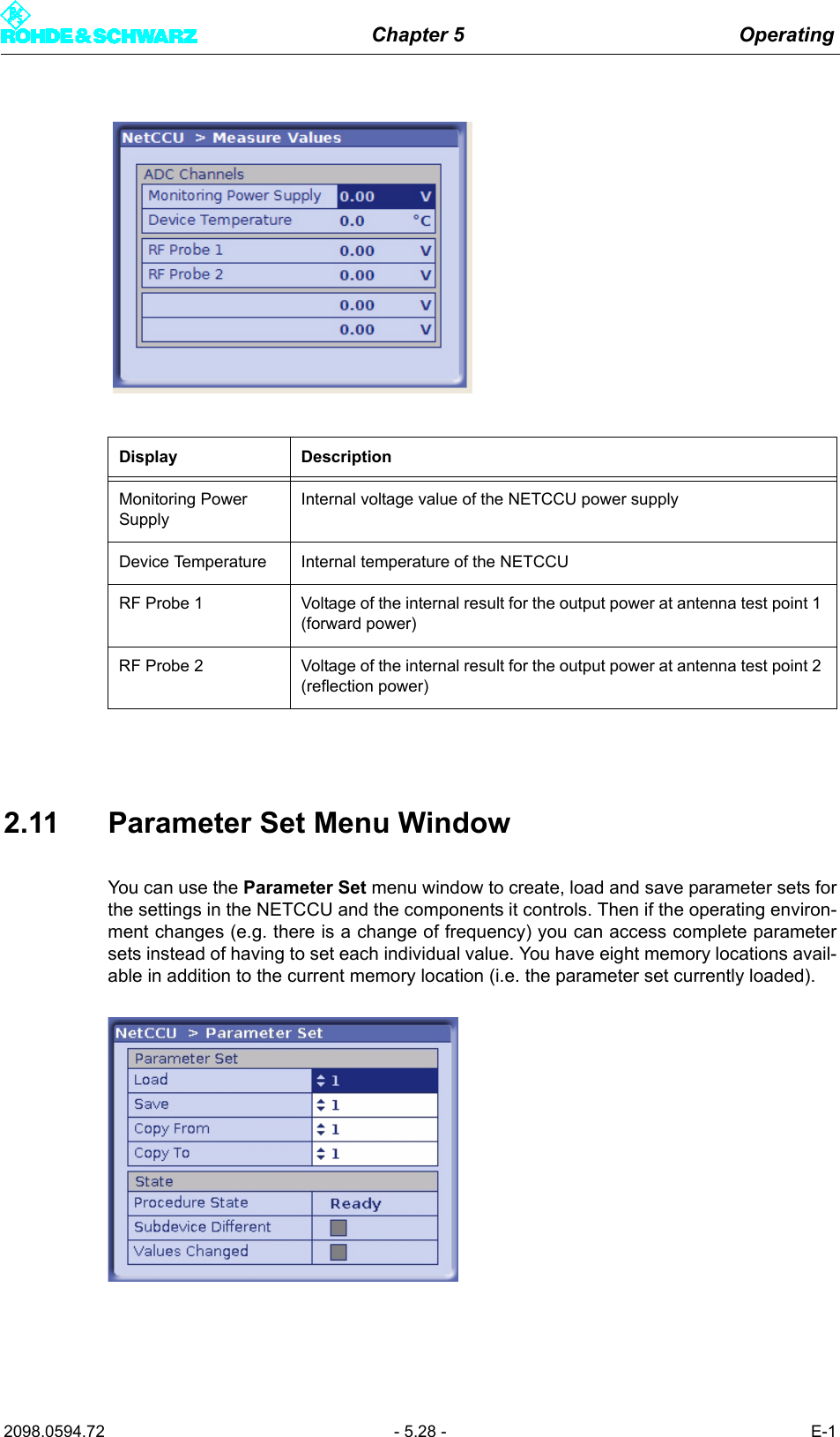
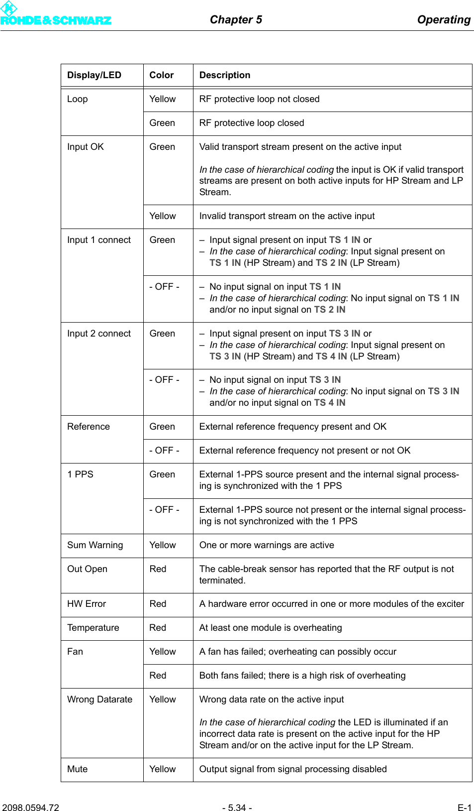
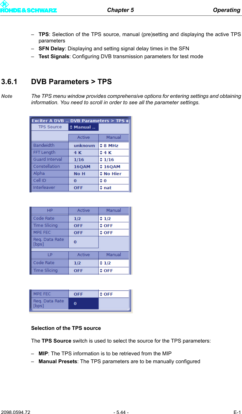
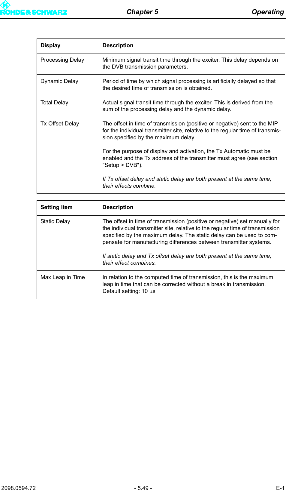
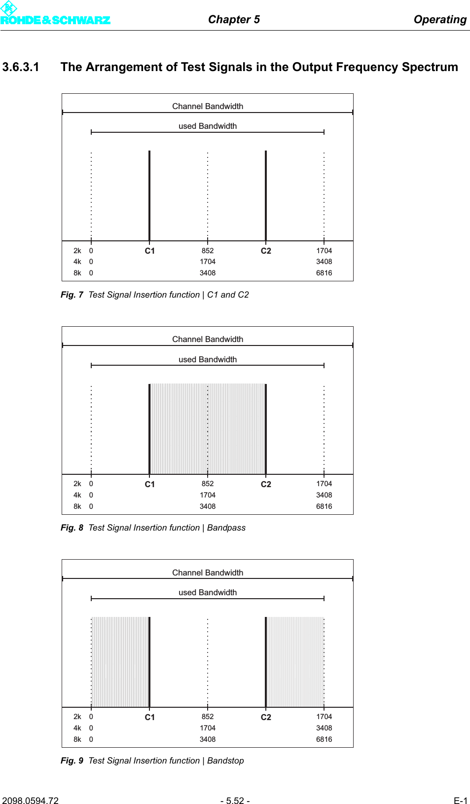
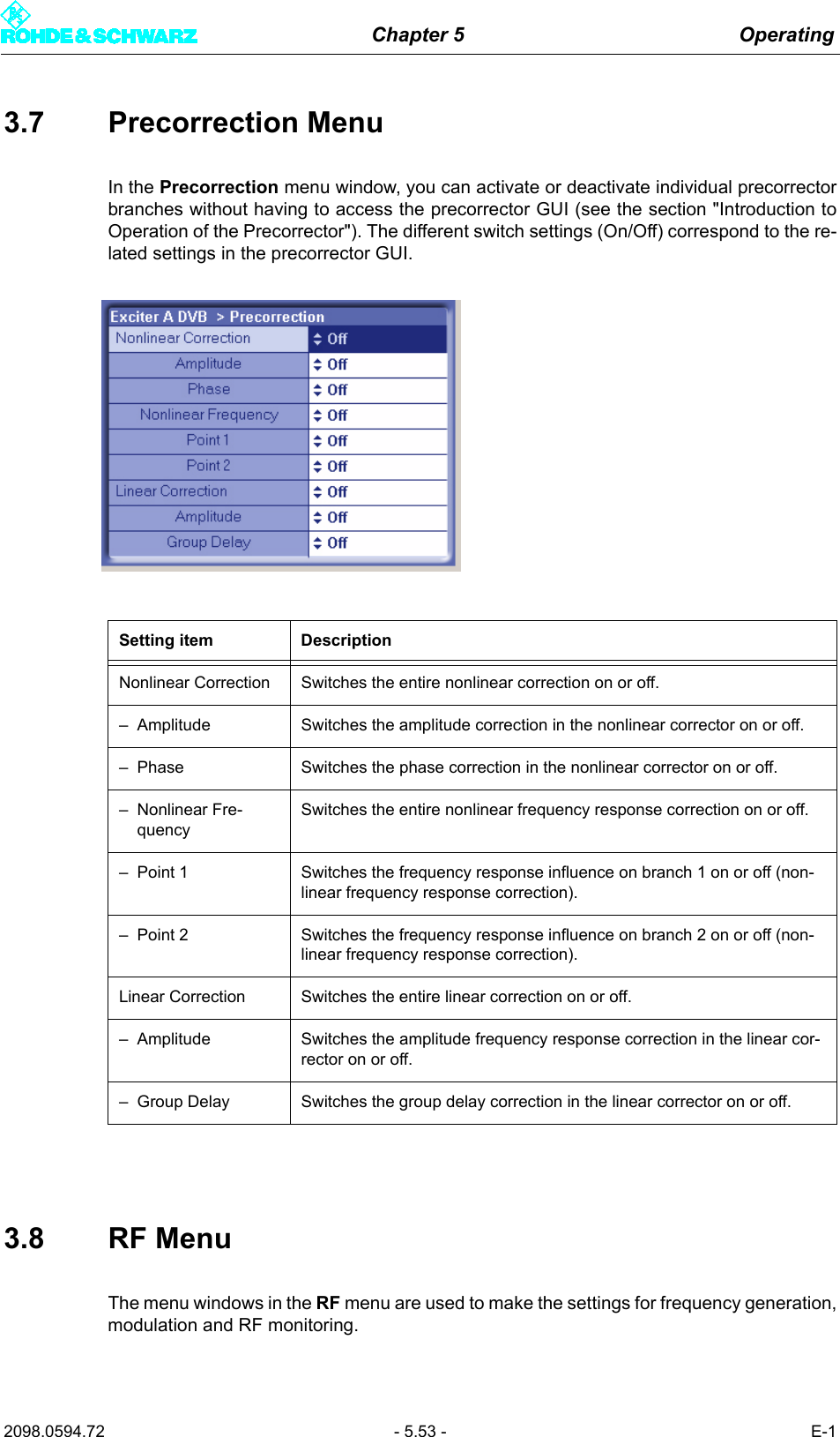
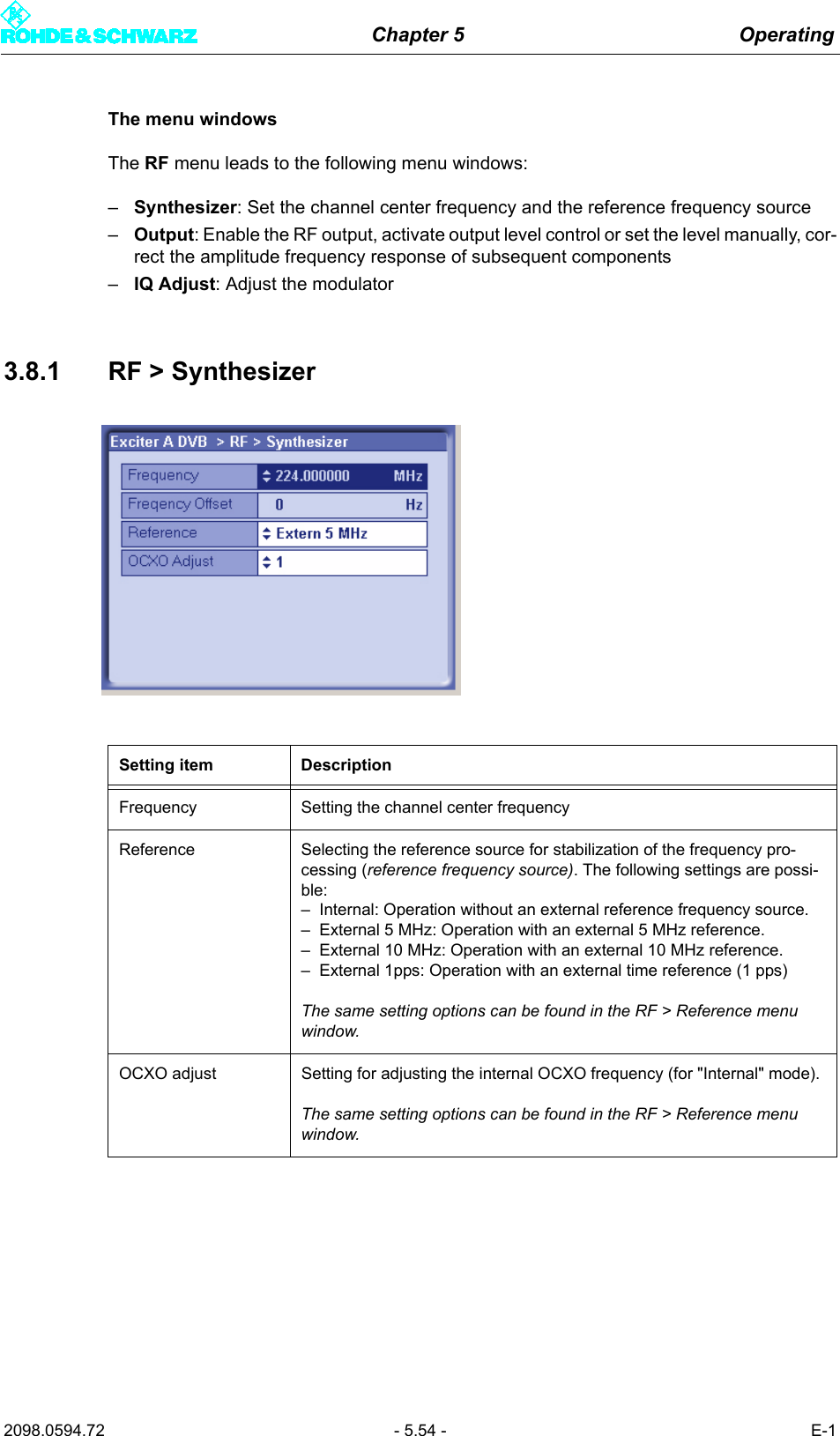
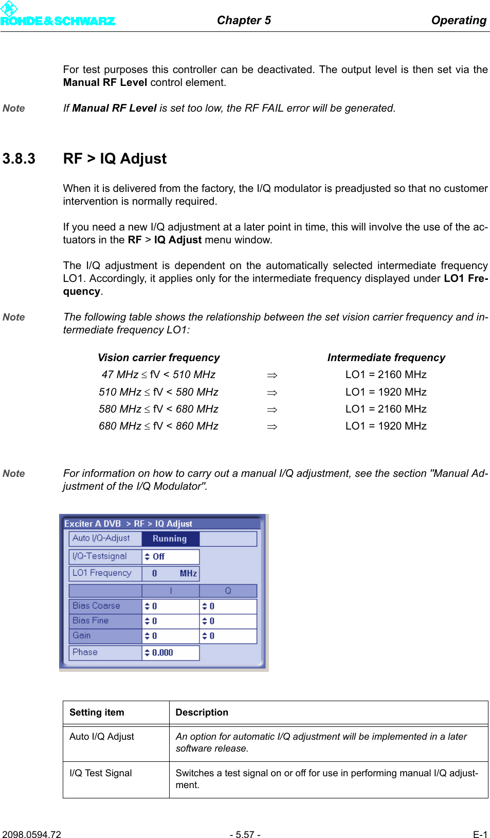
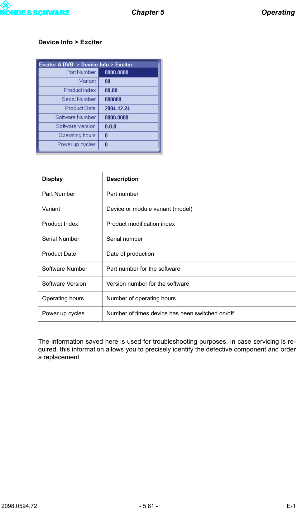
![Chapter 5 Operating2098.0594.72 - 5.32 - E-1DVB Parameters > Test Signals > Setting items:–PRBS Insertion– Test Signal Insertion– Carrier 1– Carrier 2Precorrection > Setting items:– Nonlinear Correction– Amplitude– Phase– Nonlinear Frequency– Point 1– Point 2– Linear Correction– Amplitude– Group DelayRF > Synthesizer > Setting items:– Frequency– Frequency Offset– Reference–OCXO AdjustRF > Output > Setting items:– RF Output– Regulation– Manual RF Level– Output Attenuation– RF Slope– Modulation SlopeDisplays:– AGC RegulationRF > IQ Adjust > Setting items:– I/Q Testsignal– Bias Coarse [I/Q]– Bias Fine [I/Q]– Gain [I/Q]–PhaseDisplays:– Auto I/Q Adjust– LO1 FrequencyReference Setting items– Reference–OCXO Adjust– Mute on PPS Fail– Mute on Ref. Fail–Fail Delay TimeDevice Info > Exciter > Displays:– Part Number– Variant– Product index– Serial Number– Product Date– Software Number– Software Version– Operating hours– Power up cyclesLevel 1 > Level 2 / 3> Parameters](https://usermanual.wiki/Acrodyne/NW8201E.Users-Manual-Part-13/User-Guide-864578-Page-38.png)
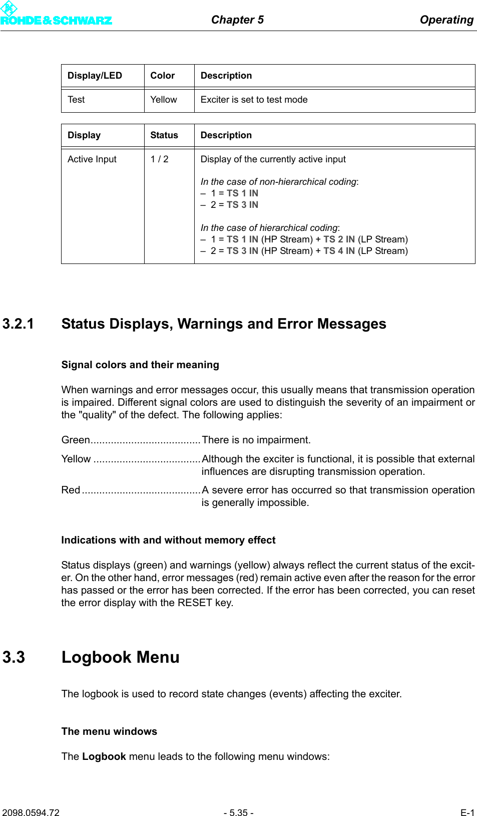
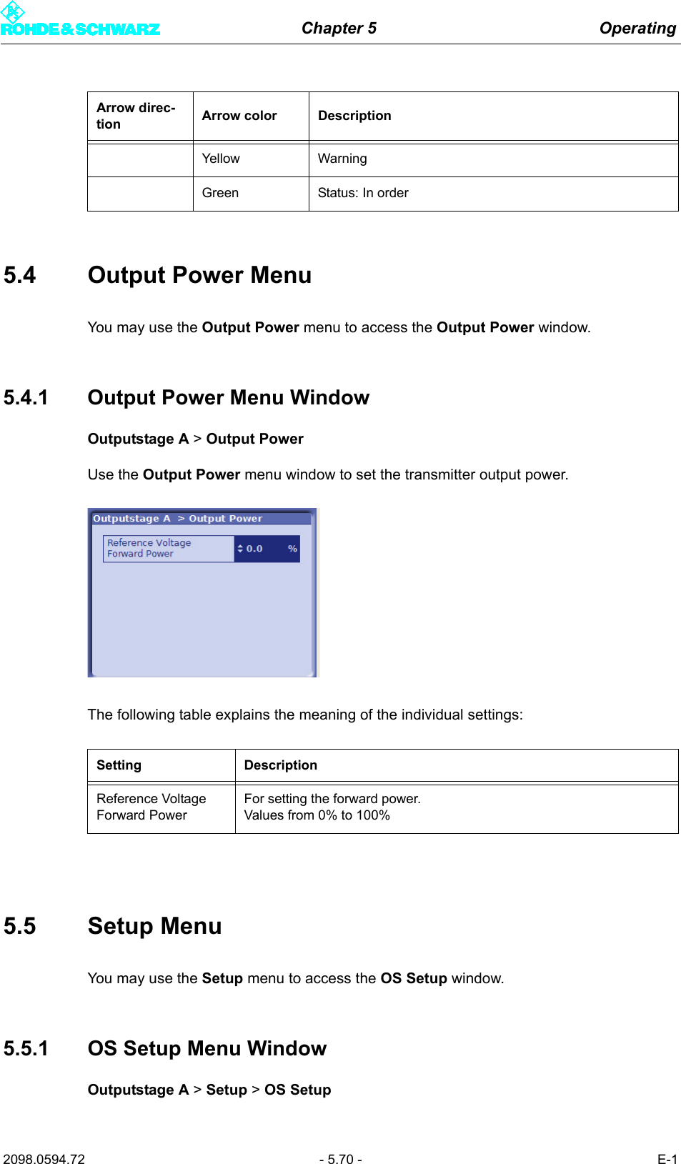
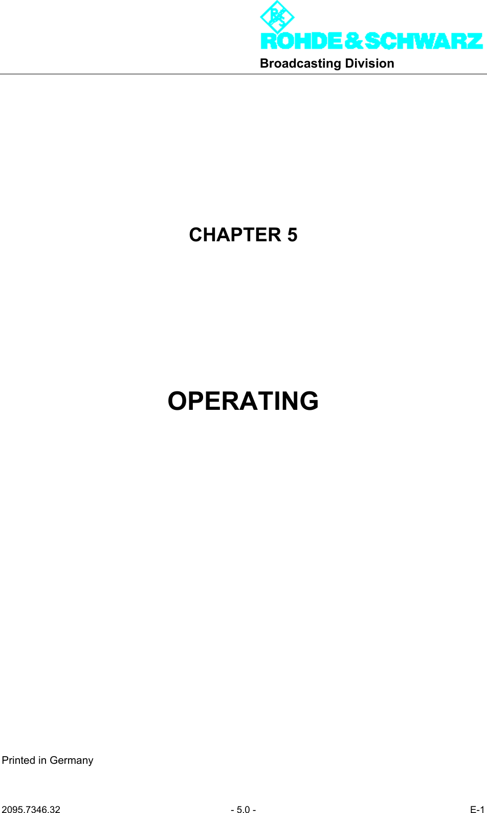
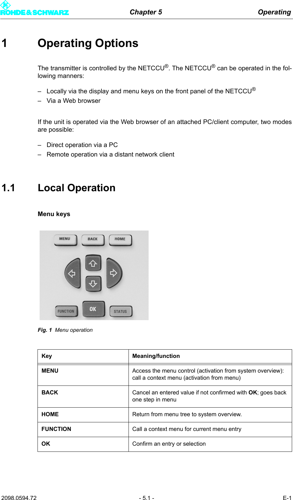
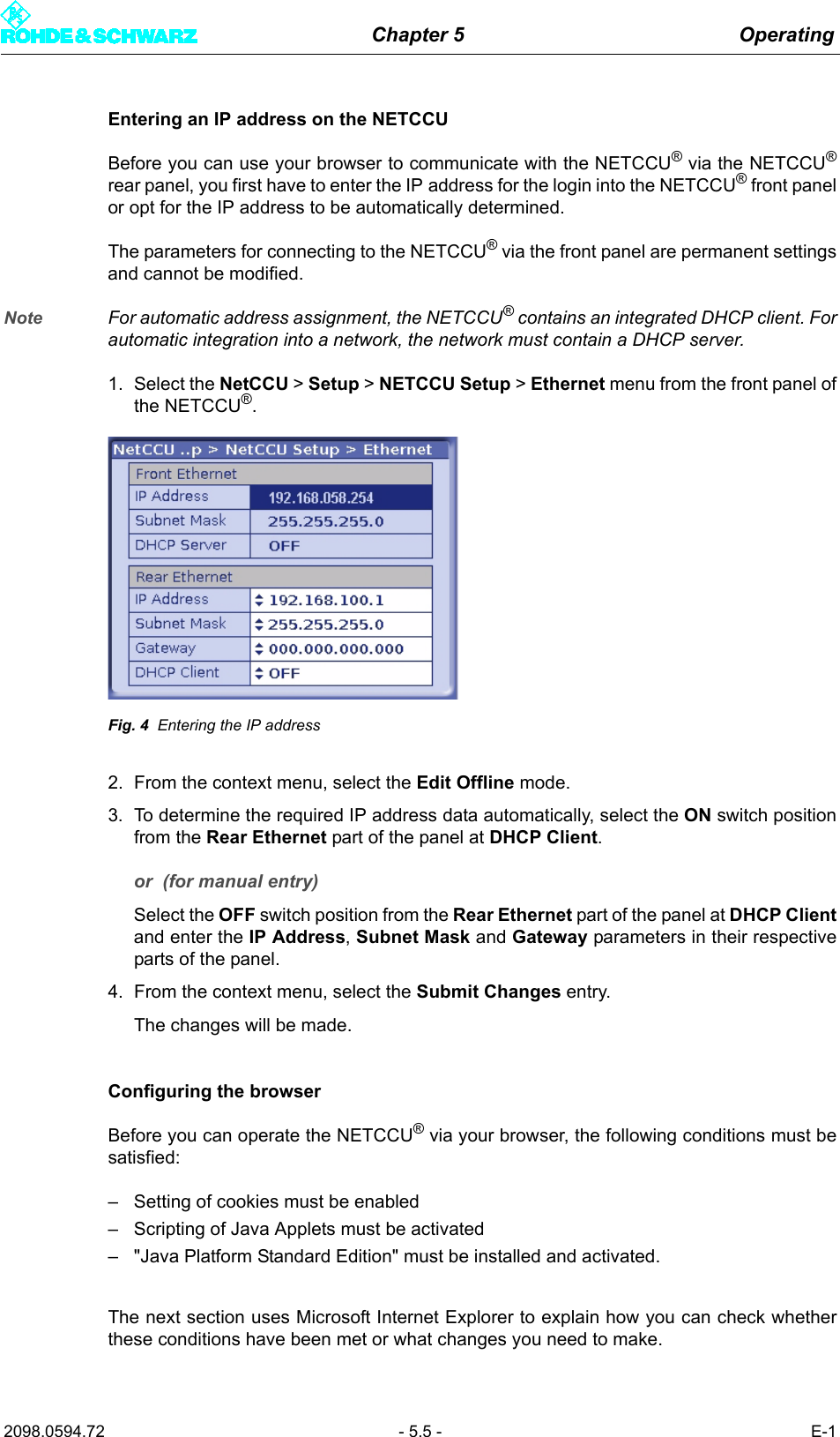
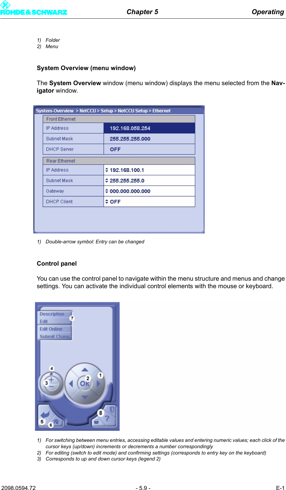
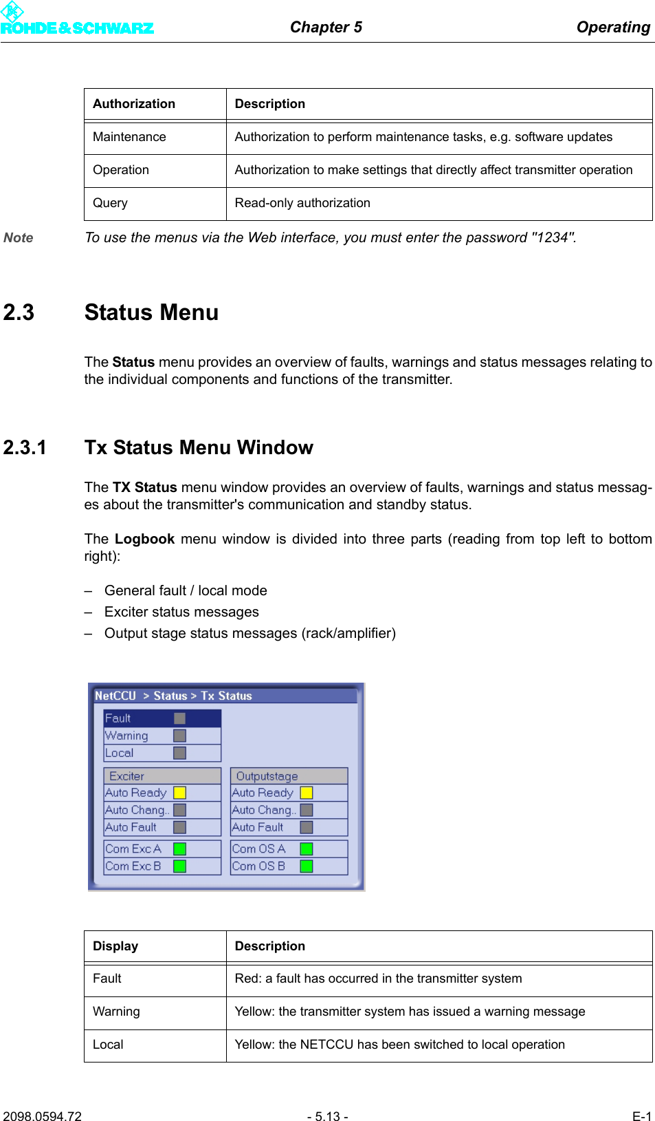
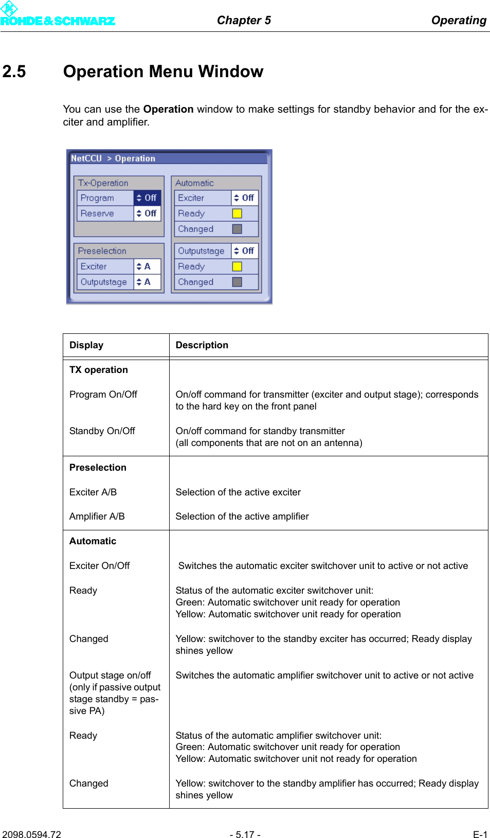
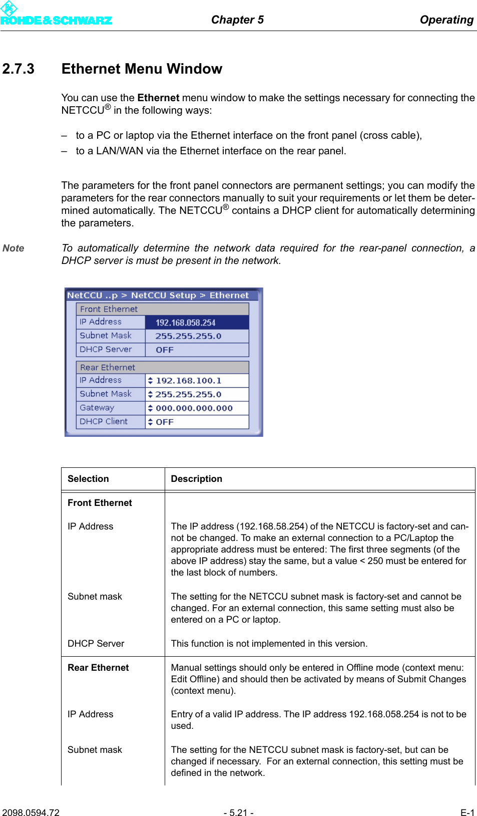
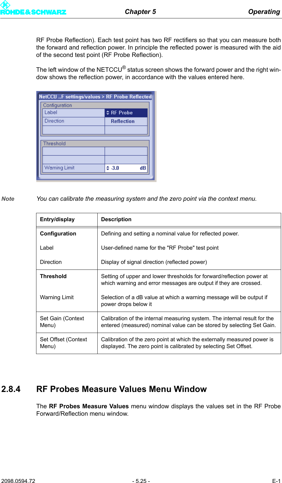
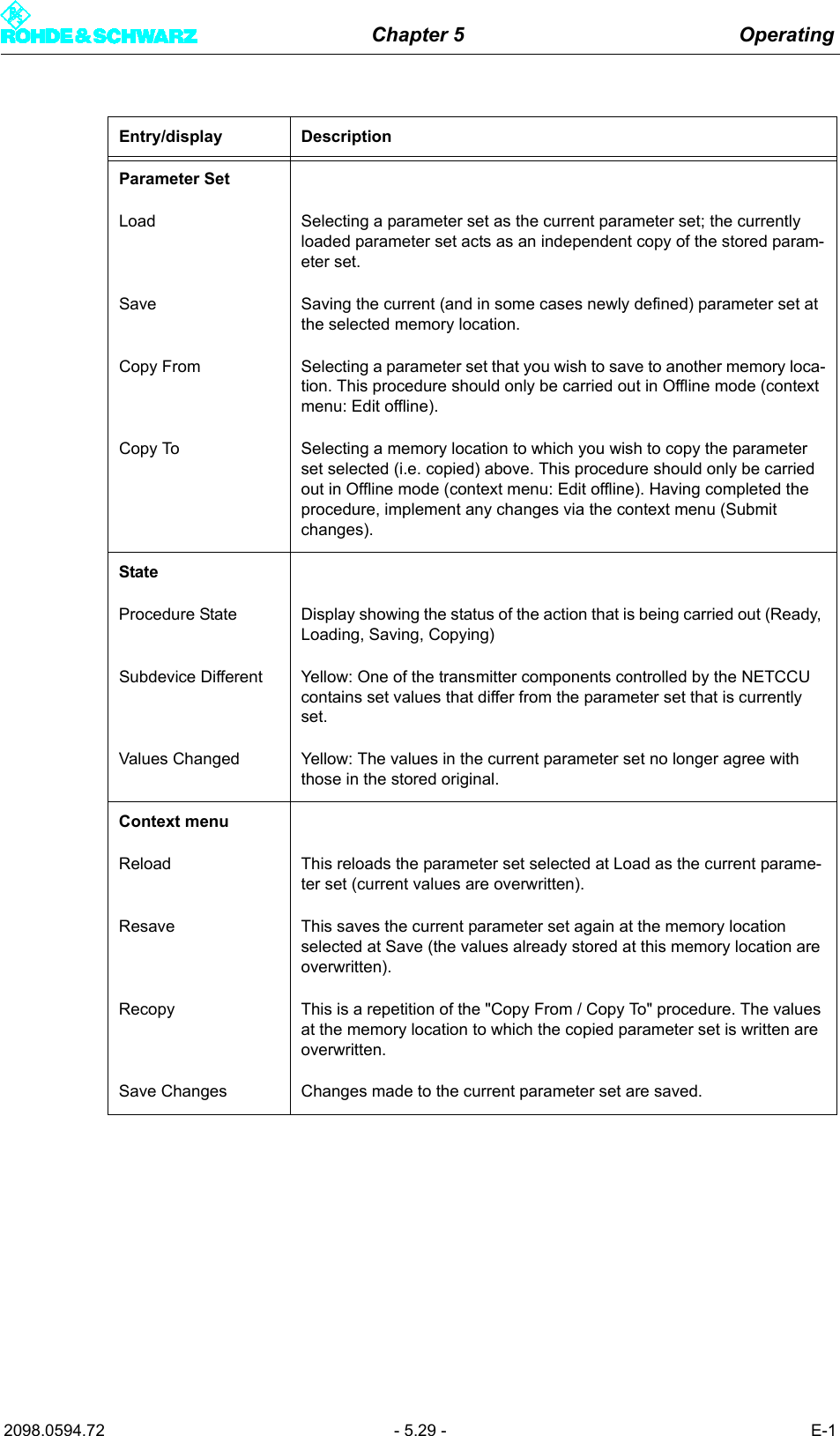
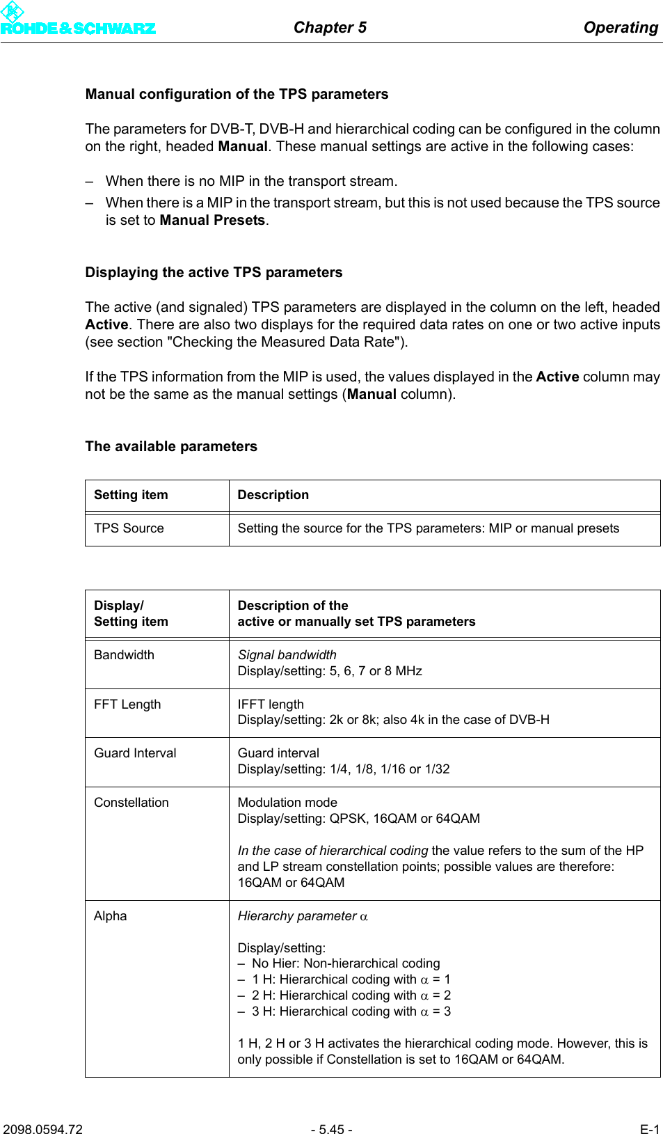
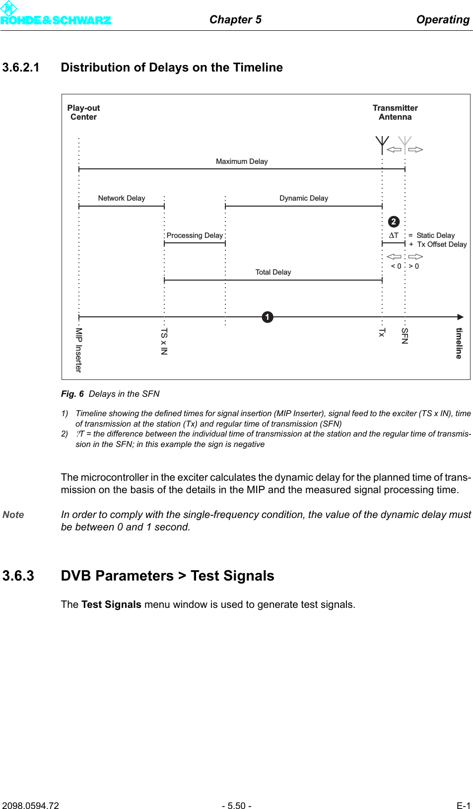
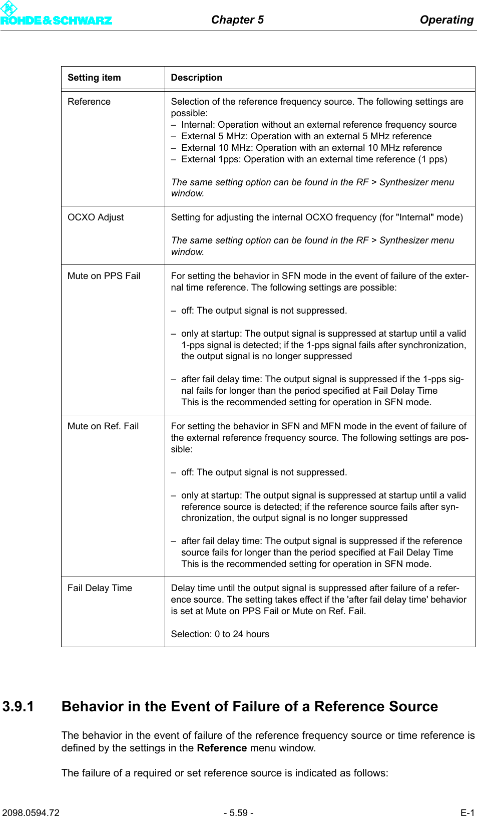
![Chapter 5 Operating2098.0594.72 - 5.39 - E-13.5.1.1 Checking the Measured Data RateBy comparing the Meas. Data Rate [bps] and Req. Data Rate [bps] displays, it is possibleto check that the input buffers (FIFO) are neither underflowing nor overflowing, since thiswould lead to breaks in transmission.Maximum data processing rate in MFN modeIn MFN mode all null packets are first of all removed from the transport stream. The asso-ciated useful data rate is then measured and displayed at Meas. Data Rate [bps]. Providedthis measured value stays below the Req. Data Rate [bps] value, trouble-free operation ispossible.Note When the useful data rate has been measured, stuffing takes place up to the data rate re-quired, that is, the difference between Req. Data Rate [bps] and Meas. Data Rate [bps]is made up by inserting null packets.Setting item DescriptionPresel. Mode[Input HP1/Input HP2]Setting the data format for the data streams HP 1 or HP 2 (operating and standby signals) on inputs TS 1 IN or TS 3 IN.The options are as follows:– AUTO: The data format is recognized automatically– ASI: Manual setting for an ASI transport stream– SMPTE: Manual setting for a SMPTE transport streamIn the case of hierarchical coding the operating or standby signal for the high priority (HP) stream is fed via the two inputs HP 1 and/or HP 2.Display DescriptionPacket Length [Input HP1/Input HP2]Display showing the packet length detected at the respective inputMeas.Data Rate [bps][Input HP1/Input HP2]Display showing the measured data rate at the respective input. In MFN mode the net data rate is displayed (without null packets).Req. Data Rate [bps][Input HP1/Input HP2]Display for checking the measured data rate. Depending on the chosen network mode, the following information is displayed:–MFN: Maximum data processing rate–SFN: Required data rateActive Mode Display showing the data format detected or set at the respective input:– ASI: As described– SMTPE: As described– Auto: Auto is selected and there is no data stream](https://usermanual.wiki/Acrodyne/NW8201E.Users-Manual-Part-13/User-Guide-864578-Page-45.png)
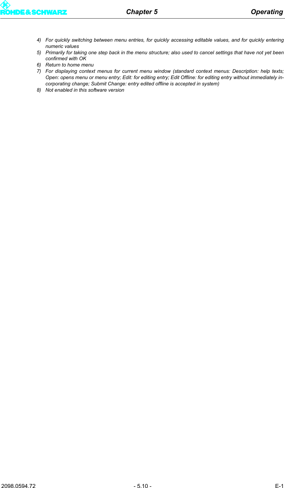
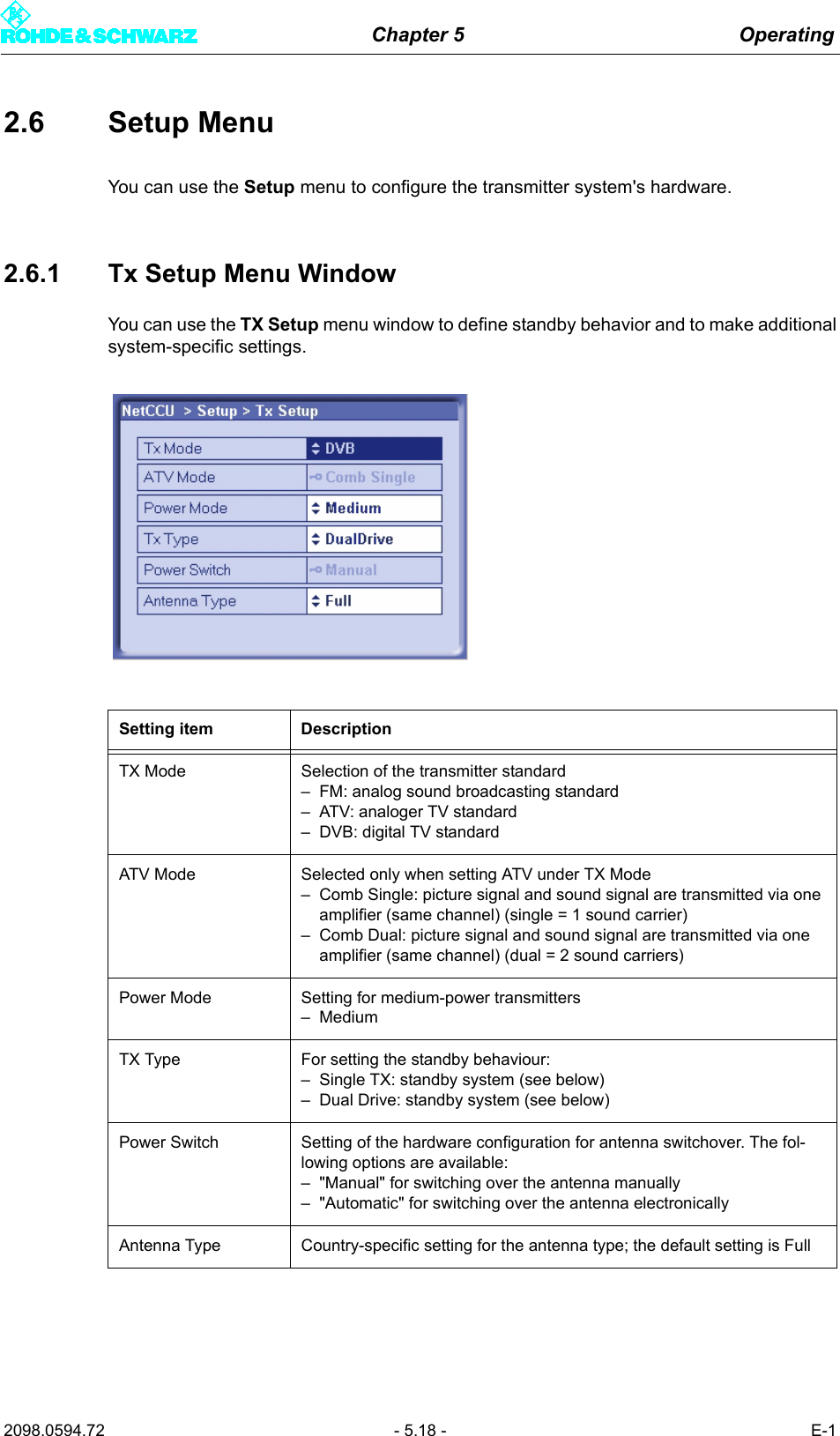
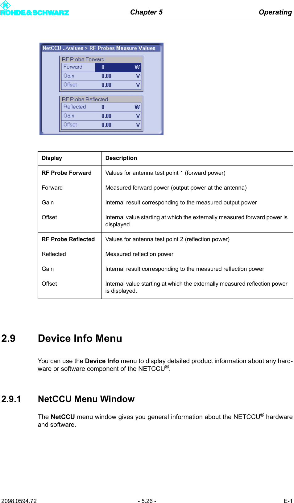
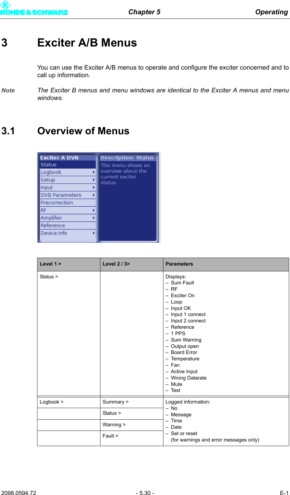
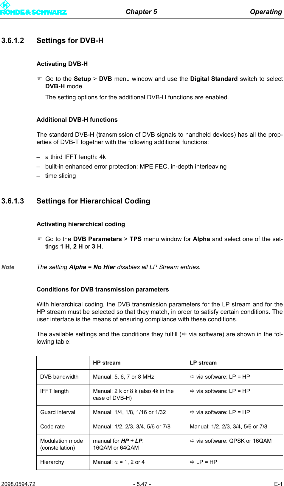
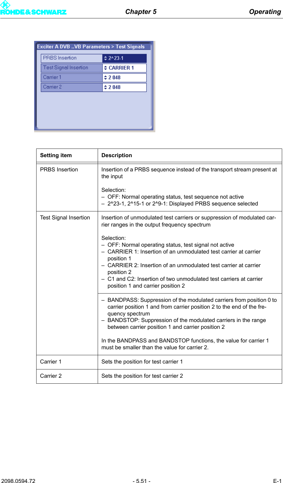
![Chapter 5 Operating2098.0594.72 - 5.40 - E-1Required data rate in SFN modeIn SFN mode the incoming transport stream is passed to processing unchanged. The as-sociated data rate is then measured and displayed at Meas. Data Rate [bps]. Provided thismeasured value matches the Req. Data Rate [bps] to within ± 1 bps, trouble-free operationis possible.3.5.2 Input > Input Config LPSetting item DescriptionPresel. Mode[Input LP1/Input LP2]In the case of hierarchical coding: Setting the data format for the low pri-ority data streams LP 1 or LP 2 (operating and standby signals) on inputs TS 2 IN or TS 4 IN.The options are as follows:– AUTO: The data format is recognized automatically– ASI: Manual setting for an ASI transport stream– SMPTE: Manual setting for a SMPTE transport streamDisplay DescriptionPacket Length [Input LP1/Input LP2]Display showing the packet length detected at the respective inputMeas.Data Rate [bps][Input LP1/Input LP2]Display showing the measured data rate at the respective input. In MFN mode the net data rate is displayed (without null packets).Req. Data Rate [bps][Input LP1/Input LP2]Display for checking the measured data rate. Depending on the chosen network mode, the following information is displayed:–MFN: Maximum data processing rate–SFN: Required data rateActive Mode Display showing the data format detected or set at the respective input:– ASI: As described– SMTPE: As described– Auto: Auto is selected and there is no data stream](https://usermanual.wiki/Acrodyne/NW8201E.Users-Manual-Part-13/User-Guide-864578-Page-46.png)
![Chapter 5 Operating2098.0594.72 - 5.46 - E-13.6.1.1 Settings for DVB-TThe following quantities form the standard parameters for DVB-T:–DVB signal bandwidth: Spectrum bandwidth in the transmit channel–IFFT length: The signal bandwidth is divided into 2k (2048) or 8k (8192) frequency sub-carriers. The 4k (4096) option is available for DVB-H only.–Guard interval: A protection interval of 1/4, 1/8, 1/16 or 1/32 symbol length. The longerthe guard interval, the better the intersymbol echo suppression.–Code rate: Error correction bits (1/2, 2/3, 3/4, 5/6 or 7/8) added to the information datain the FEC (forward error correction) block. For instance, a code rate of 5/6 correspondsto a ratio of 5:1 between information data and FEC.–Modulation mode: Depending on the modulation mode, a frequency subcarrier may con-tain 2-bit (QPSK), 4-bit (16QAM) or 6-bit (64QAM) information.Cell ID Cell IDDisplay/setting: 0x0000 to 0xFFFFThe Cell ID can only be retrieved from the MIP if the Tx Automatic is activated and the Tx address is correctly set (see section "Setup > DVB").For the purpose of signaling in the output signal (TPS), Parameter Cell ID Enable must also be activated (see section "Setup > DVB").Interleaver InterleaverDisplay/setting:– nat: Default setting ("native") with normal function for DVB-T– in depth: 8k interleaving for DVB-H at IFFT lengths of 2k and 4k for improved transmission reliability (DVB-H parameter)Code Rate [HP/LP] Internal code rate (separate for HP and LP stream)Display/setting: 1/2, 2/3, 3/4, 5/6 or 6/7 Time Slicing [HP/LP] Time Slicing Flag (DVB-H parameter)Display/setting separate for HP and LP stream:– OFF: Default setting; no signaling via flag– ON: A flag is set in the broadcast DVB signal. This flag informs the receiver that at least one service in the DVB-H data stream uses time slicing.MPE FEC [HP/LP] MPE FEC Flag (DVB-H parameter)Display/setting separate for HP and LP stream:– OFF: Default setting; no signaling via flag– ON: This flag informs the receiver that at least one service in the DVB-H data stream uses forward error correction for MPE (multipro-tocol encapsulation).Req. Data Rate [HP/LP]Display showing the required data rate;cf. section "Input > Input Config HP"Display/Setting itemDescription of theactive or manually set TPS parameters](https://usermanual.wiki/Acrodyne/NW8201E.Users-Manual-Part-13/User-Guide-864578-Page-52.png)
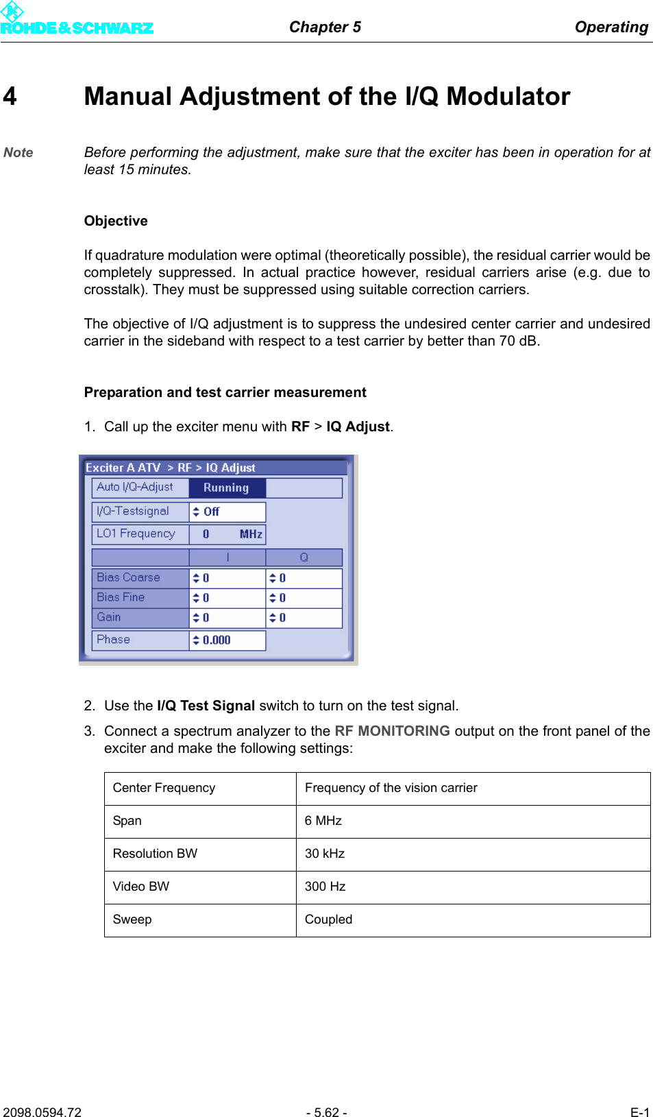
![Chapter 5 Operating2098.0594.72 - 5.58 - E-13.9 Reference MenuA reference source for stabilization of the frequency processing (reference frequencysource) can be selected via the Reference menu window.It is also possible to set the behavior of the exciter in the event of failure of the referencesources for frequency processing and for synchronization in the SFN (external 1-pps sig-nal).Bias Coarse [I/Q] Course setting of an actuator for suppressing the undesired center car-rier; setting range: -1023 to +1023Bias Fine [I/Q] Fine setting of an actuator for suppressing the undesired center carrier; setting range: -32767 to +32767Gain (I/Q) Setting of an actuator for suppressing the undesired carrier in the side-band; setting range: 0 to 255Phase Setting of an actuator for suppressing the undesired carrier in the side-band; setting range: -14 to +14Display DescriptionLO1 Frequency Display of the intermediate frequency LO1 which is automatically set in the modulator (1.92 GHz or 2.16 GHz)The adjustment values for the actuators described above apply only for the displayed intermediate frequency.Setting item Description](https://usermanual.wiki/Acrodyne/NW8201E.Users-Manual-Part-13/User-Guide-864578-Page-64.png)
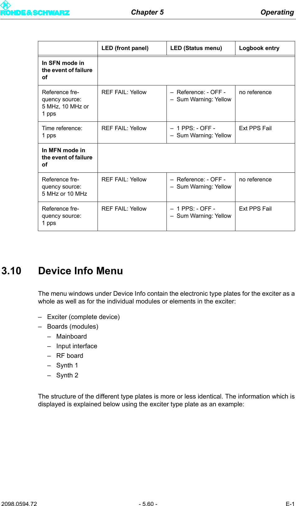
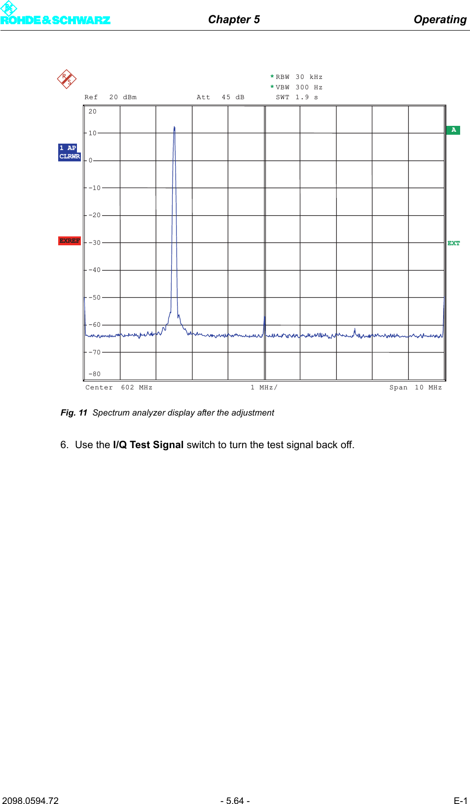
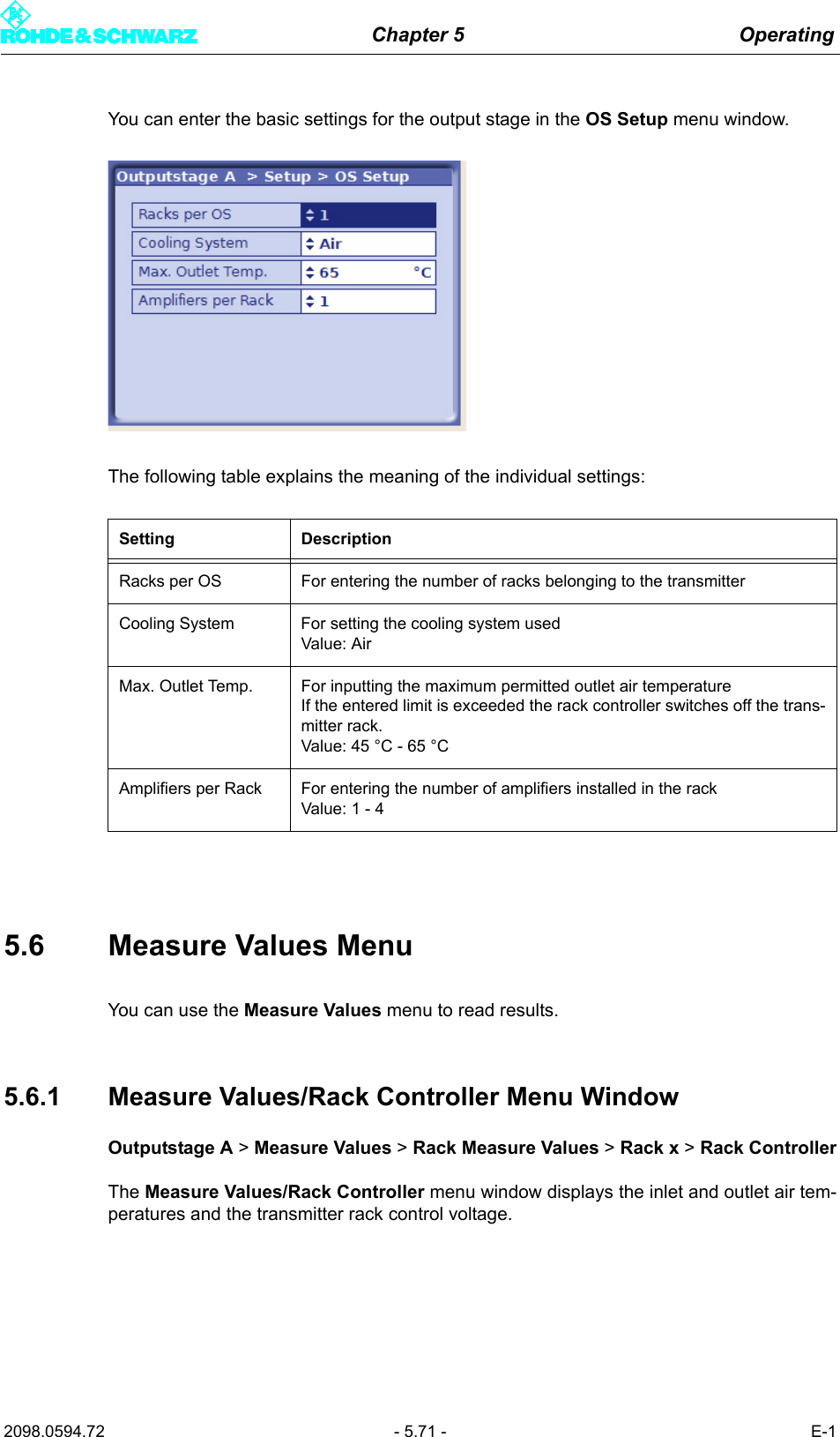
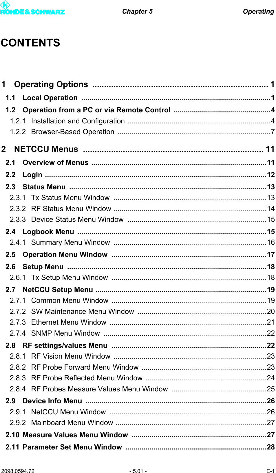
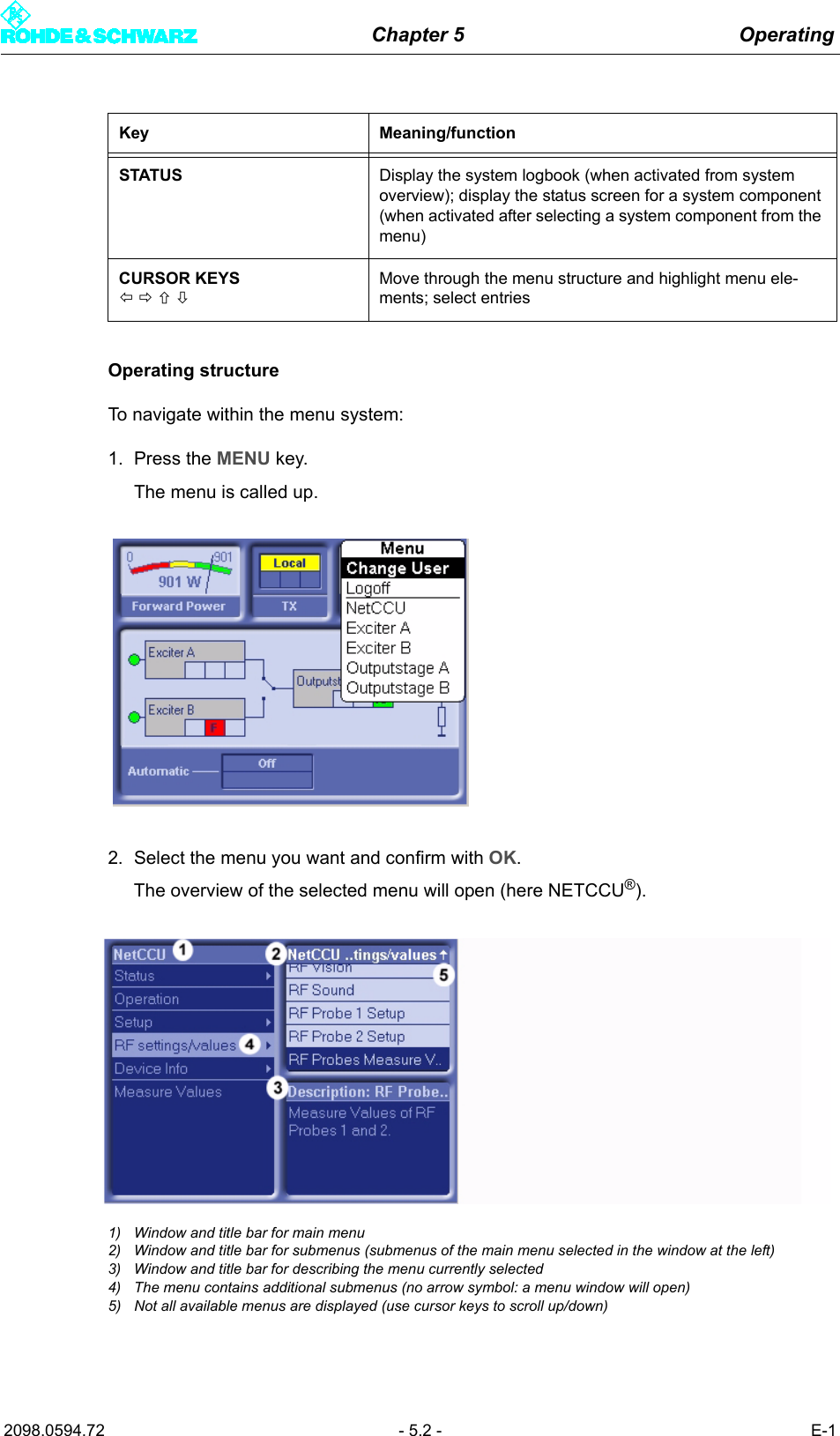
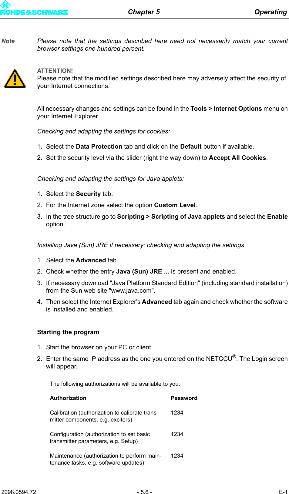
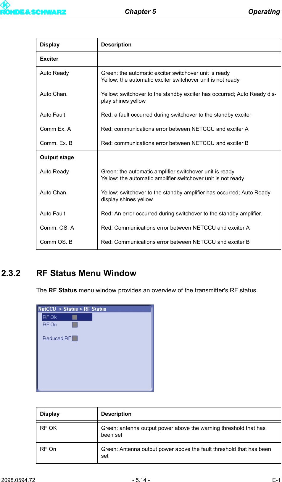
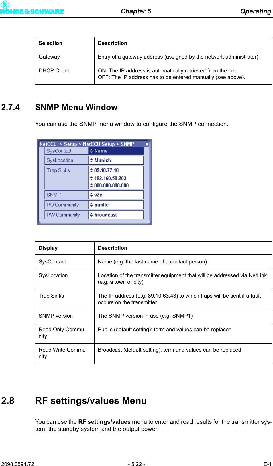
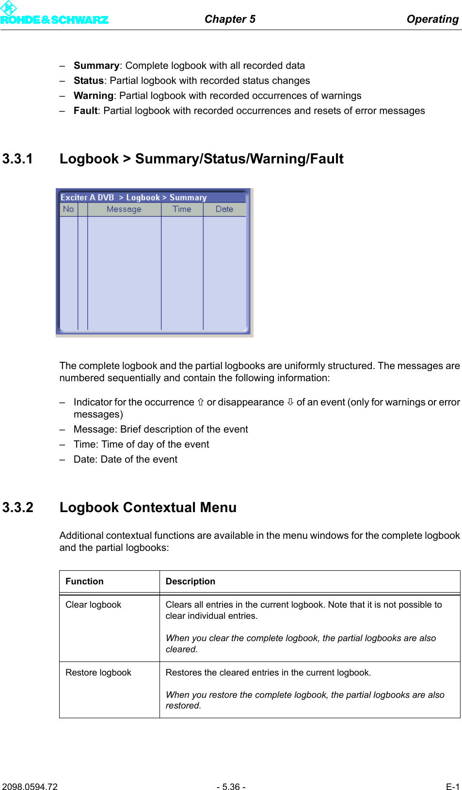
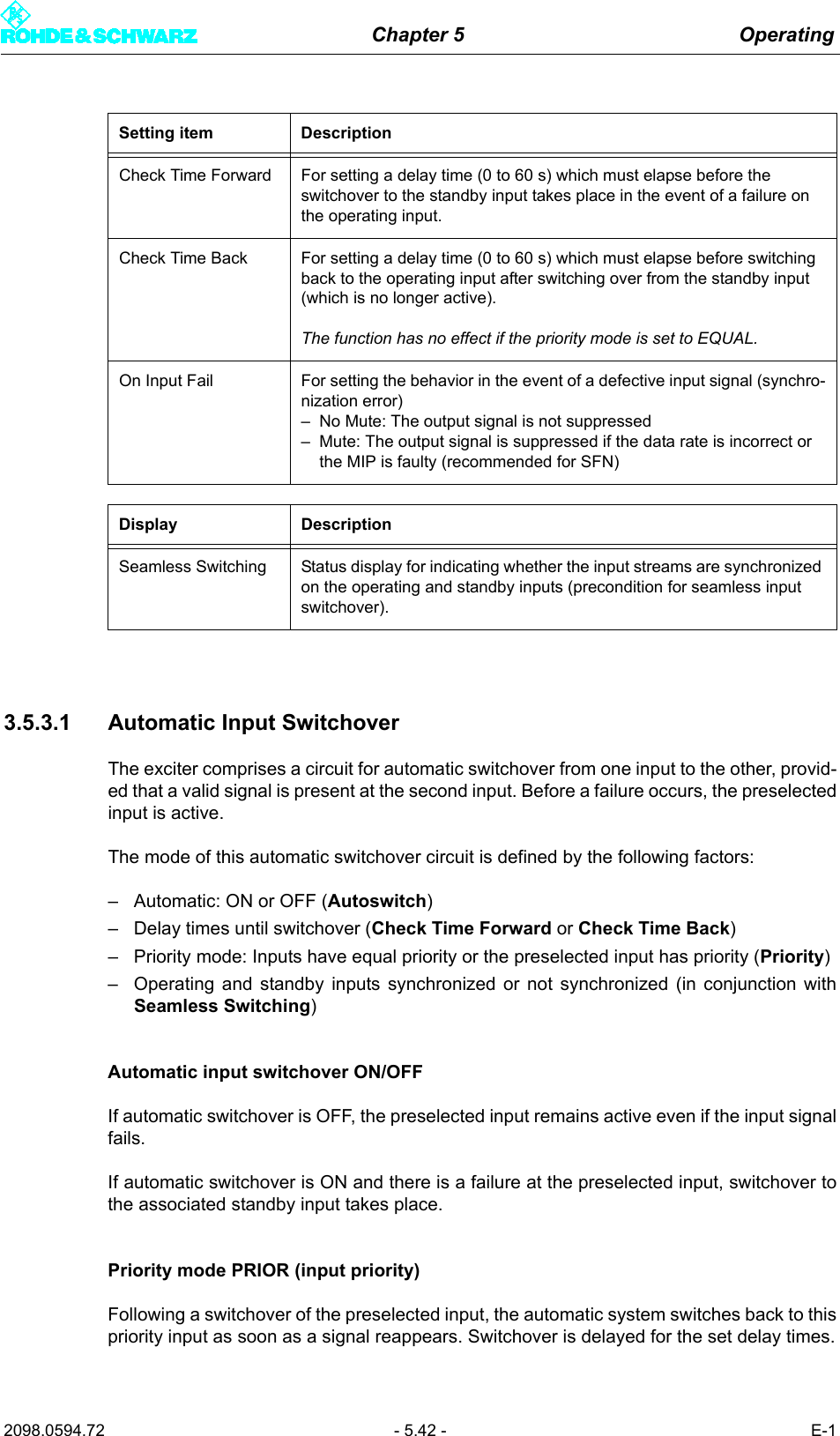
![Chapter 5 Operating2098.0594.72 - 5.63 - E-1Fig. 10 Spectrum analyzer display prior to adjustment1) Undesired carrier in the sideband at the vision carrier frequency + 2.5 MHz2) Undesired center carrier at the vision carrier frequency3) Desired test carrier at the vision carrier frequency - 2.5 MHzImplementation1. Set the Bias Fine [I/Q] actuators to zero.2. Course adjustment, center carrier: Using the Bias Coarse [I/Q] actuators, suppress theundesired center carrier as much as possible with respect to the test carrier. You shouldindividually adjust each actuator going back and forth several times until you achieve anoptimum value.3. Sideband adjustment: Use the Gain [I/Q] and Phase actuators to suppress the undes-ired carrier in the sideband by more than 70 dB with respect to the test carrier. Youshould individually adjust each actuator going back and forth several times until youachieve an optimum value.4. Course adjustment, center carrier optimization: Using the Bias Coarse [I/Q] actuators,suppress the undesired center carrier as much as possible with respect to the test car-rier. You should individually adjust each actuator going back and forth several times untilyou achieve an optimum value.5. Fine adjustment, center carrier: If the center carrier is suppressed by less than 70 dB,carry out a fine adjustment using the Bias Fine [I/Q] actuators. 1APCLRWRARef 20 dBm Att 45 dBEXTEXREFCenter 602 MHz Span 10 MHz1 MHz/*RBW 30 kHz*VBW 300 HzSWT 1.9 s-80-70-60-50-40-30-20-1001020132](https://usermanual.wiki/Acrodyne/NW8201E.Users-Manual-Part-13/User-Guide-864578-Page-69.png)