Acrodyne NW8201E DIGITAL TELEVISION BROADCAST TRANSMITTER User Manual 32 NV8202 26 04 06 01 00
Acrodyne Industries, Inc. DIGITAL TELEVISION BROADCAST TRANSMITTER 32 NV8202 26 04 06 01 00
Acrodyne >
Contents
- 1. Users Manual Part 1
- 2. Users Manual Part 2
- 3. Users Manual Part 3
- 4. Users Manual Part 4
- 5. Users Manual Part 5
- 6. Users Manual Part 6
- 7. Users Manual Part 7
- 8. Users Manual Part 8
- 9. Users Manual Part 9
- 10. Users Manual Part 10
- 11. Users Manual Part 11
- 12. USers Manual Part 12
- 13. Users Manual Part 13
- 14. Users Manual Part 14
- 15. Users Manual Part 15
- 16. Users Manual Part 16
- 17. Users Manual Part 17
- 18. Users Manual Part 18
- 19. Users Manual Part 19
- 20. Users Manual Part 20
Users Manual Part 13

Broadcasting Division
2095.7346.32 - 5.0 - E-1
CHAPTER 5
OPERATING
Printed in Germany

Chapter 5 Operating
2098.0594.72 - 5.01 - E-1
CONTENTS
1 Operating Options ........................................................................... 1
1.1 Local Operation ..............................................................................................1
1.2 Operation from a PC or via Remote Control ................................................4
1.2.1 Installation and Configuration .......................................................................4
1.2.2 Browser-Based Operation ............................................................................7
2 NETCCU Menus ............................................................................. 11
2.1 Overview of Menus .......................................................................................11
2.2 Login ..............................................................................................................12
2.3 Status Menu ..................................................................................................13
2.3.1 Tx Status Menu Window ............................................................................13
2.3.2 RF Status Menu Window ............................................................................14
2.3.3 Device Status Menu Window .....................................................................15
2.4 Logbook Menu ..............................................................................................15
2.4.1 Summary Menu Window ............................................................................16
2.5 Operation Menu Window .............................................................................17
2.6 Setup Menu ...................................................................................................18
2.6.1 Tx Setup Menu Window .............................................................................18
2.7 NetCCU Setup Menu .....................................................................................19
2.7.1 Common Menu Window .............................................................................19
2.7.2 SW Maintenance Menu Window ................................................................20
2.7.3 Ethernet Menu Window ..............................................................................21
2.7.4 SNMP Menu Window .................................................................................22
2.8 RF settings/values Menu .............................................................................22
2.8.1 RF Vision Menu Window ............................................................................23
2.8.2 RF Probe Forward Menu Window ..............................................................23
2.8.3 RF Probe Reflected Menu Window ............................................................24
2.8.4 RF Probes Measure Values Menu Window ...............................................25
2.9 Device Info Menu ..........................................................................................26
2.9.1 NetCCU Menu Window ..............................................................................26
2.9.2 Mainboard Menu Window ...........................................................................27
2.10 Measure Values Menu Window ...................................................................27
2.11 Parameter Set Menu Window ......................................................................28

Chapter 5 Operating
2098.0594.72 - 5.02 - E-1
3 Exciter A/B Menus ......................................................................... 30
3.1 Overview of Menus .......................................................................................30
3.2 Status Menu ..................................................................................................33
3.2.1 Status Displays, Warnings and Error Messages ........................................35
3.3 Logbook Menu ..............................................................................................35
3.3.1 Logbook > Summary/Status/Warning/Fault ...............................................36
3.3.2 Logbook Contextual Menu .........................................................................36
3.4 Setup Menu ...................................................................................................37
3.4.1 Setup > DVB ..............................................................................................37
3.5 Input Menu ....................................................................................................38
3.5.1 Input > Input Config HP ..............................................................................38
3.5.1.1 Checking the Measured Data Rate .................................................................. 39
3.5.2 Input > Input Config LP ..............................................................................40
3.5.2.1 Checking the Measured Data Rate .................................................................. 41
3.5.3 Input > Input Automatic ..............................................................................41
3.5.3.1 Automatic Input Switchover .............................................................................. 42
3.5.3.2 Behavior in the Event of a Defective Input Signal ............................................ 43
3.6 DVB Parameters Menu .................................................................................43
3.6.1 DVB Parameters > TPS .............................................................................44
3.6.1.1 Settings for DVB-T ........................................................................................... 46
3.6.1.2 Settings for DVB-H ........................................................................................... 47
3.6.1.3 Settings for Hierarchical Coding ....................................................................... 47
3.6.2 DVB Parameters > SFN Delay ...................................................................48
3.6.2.1 Distribution of Delays on the Timeline .............................................................. 50
3.6.3 DVB Parameters > Test Signals ................................................................50
3.6.3.1 The Arrangement of Test Signals in the Output Frequency Spectrum ............. 52
3.7 Precorrection Menu ......................................................................................53
3.8 RF Menu ........................................................................................................53
3.8.1 RF > Synthesizer ........................................................................................54
3.8.1.1 Reference Frequency Source .......................................................................... 55
3.8.1.2 Holdover Mode (In Case of Failure of the Reference Frequency) .................... 55
3.8.2 RF > Output ................................................................................................56
3.8.2.1 Output Level Control ........................................................................................ 56
3.8.3 RF > IQ Adjust ............................................................................................57
3.9 Reference Menu ............................................................................................58
3.9.1 Behavior in the Event of Failure of a Reference Source ............................59
3.10 Device Info Menu ..........................................................................................60
4 Manual Adjustment of the I/Q Modulator ..................................... 62

Chapter 5 Operating
2098.0594.72 - 5.03 - E-1
5 Outputstage A/B Menus ................................................................ 65
5.1 Overview of Menus .......................................................................................65
5.2 Status Menu ..................................................................................................66
5.2.1 OS Status Menu Window ...........................................................................66
5.2.2 Status/Rack Controller Menu Window ........................................................67
5.3 Logbook Menu ..............................................................................................69
5.3.1 Logbook Menu Window ..............................................................................69
5.4 Output Power Menu ......................................................................................70
5.4.1 Output Power Menu Window ......................................................................70
5.5 Setup Menu ...................................................................................................70
5.5.1 OS Setup Menu Window ............................................................................70
5.6 Measure Values Menu ..................................................................................71
5.6.1 Measure Values/Rack Controller Menu Window ........................................71
5.7 Device Info Menu ..........................................................................................72
5.7.1 Device Info/Rack Controller Menu Window ................................................72

Chapter 5 Operating
2098.0594.72 - 5.1 - E-1
1 Operating Options
The transmitter is controlled by the NETCCU®. The NETCCU® can be operated in the fol-
lowing manners:
– Locally via the display and menu keys on the front panel of the NETCCU®
– Via a Web browser
If the unit is operated via the Web browser of an attached PC/client computer, two modes
are possible:
– Direct operation via a PC
– Remote operation via a distant network client
1.1 Local Operation
Menu keys
Fig. 1 Menu operation
Key Meaning/function
MENU Access the menu control (activation from system overview):
call a context menu (activation from menu)
BACK Cancel an entered value if not confirmed with OK; goes back
one step in menu
HOME Return from menu tree to system overview.
FUNCTION Call a context menu for current menu entry
OK Confirm an entry or selection
Chapter 5 Operating
2098.0594.72 - 5.2 - E-1
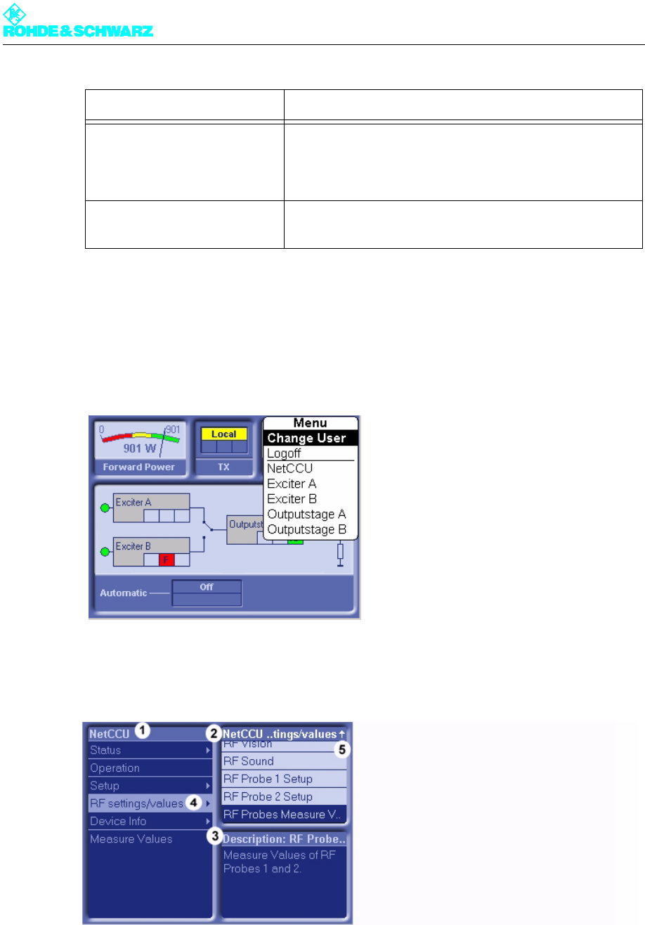
Operating structure
To navigate within the menu system:
1. Press the MENU key.
The menu is called up.
2. Select the menu you want and confirm with OK.
The overview of the selected menu will open (here NETCCU®).
1) Window and title bar for main menu
2) Window and title bar for submenus (submenus of the main menu selected in the window at the left)
3) Window and title bar for describing the menu currently selected
4) The menu contains additional submenus (no arrow symbol: a menu window will open)
5) Not all available menus are displayed (use cursor keys to scroll up/down)
STATUS Display the system logbook (when activated from system
overview); display the status screen for a system component
(when activated after selecting a system component from the
menu)
CURSOR KEYS
Õ Ö × Ø
Move through the menu structure and highlight menu ele-
ments; select entries
Key Meaning/function
Chapter 5 Operating
2098.0594.72 - 5.3 - E-1
3. Using the cursor keys, select a menu from the left part of the window and confirm with
OK.
The left window now shows the next menu level; the right window shows the submenus
of the entry selected at the left.
4. Using the cursor keys (up/down), select another menu or menu window from the right
side of the window and confirm with OK.
Using the cursor keys (up/down), select an entry from the menu window and confirm
with OK.
1) The entry can be edited.
2) The entry cannot be edited under the current authorization (Login).
5. Using the up/down cursor keys, select an entry or Using the left/right cursor keys, select
the value to be changed and change it using the up/down cursor keys.
6. Confirm the selection/change with OK.
7. Using the HOME key, return to the system overview.
By using the MENU or FUNCTION key, you can call up a context menu at any position.
The context menus usually contain default entries or special functions about the selected
menu/menu window/menu entry.
Use the BACK key to go back one step in the menu structure (even from the Help window):
you can also use BACK to cancel an entered value as long as you have not already con-
firmed it with OK.
Chapter 5 Operating
2098.0594.72 - 5.4 - E-1
Use the HOME key to exit the menu structure and return to the system overview.
1.2 Operation from a PC or via Remote Control
You need a Web browser in order to operate the system from a PC or via remote control.
Note Depending on their rights, logged-on users can monitor the transmitter in question or con-
trol all of its functions. There is no difference between PC control and remote control with
respect to this functionality.
The NETCCU® comes equipped with the components necessary for PC or remote control
operation:
Network port (10/100 MBit)
Network card (RJ-45)
RJ-45 crossover cable
1.2.1 Installation and Configuration
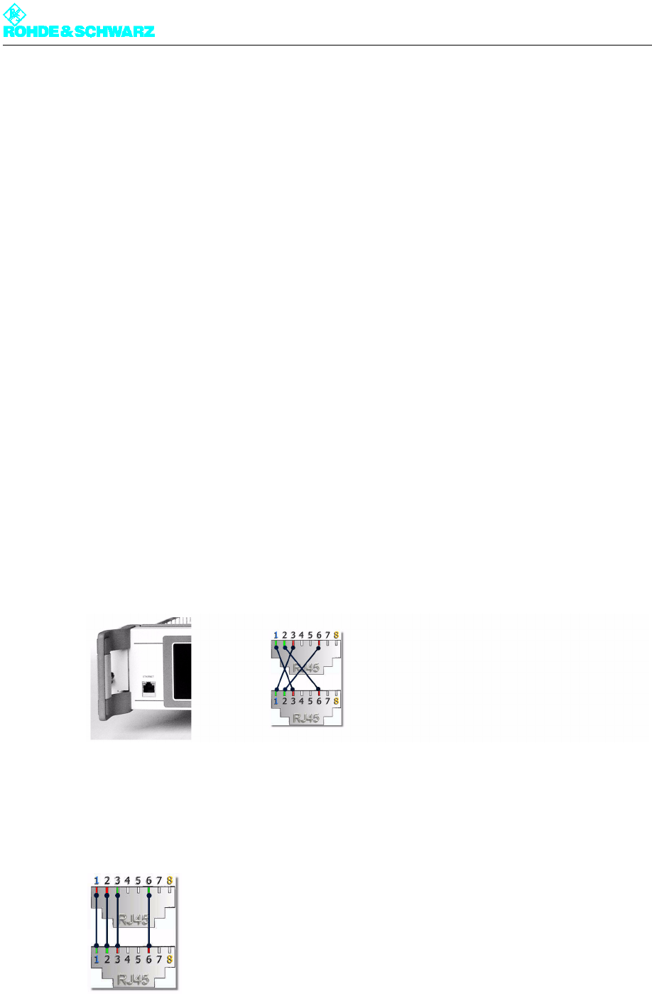
Connecting a PC/client
1. Connect the NETCCU® to a local PC with the aid of an RJ-45 crossover cable attached
at the Ethernet socket on the front panel of the unit.
Fig. 2 Ethernet link using a crossover cable connection
or
Connect the NETCCU® to your network with the aid of an RJ-45 1:1 cable attached to
the NETLINK socket (Ethernet NetLink X5) on the rear panel of the unit.
Fig. 3 Link to a network using an RJ-45 1:1 cable connection
Chapter 5 Operating
2098.0594.72 - 5.5 - E-1
Entering an IP address on the NETCCU
Before you can use your browser to communicate with the NETCCU® via the NETCCU®
rear panel, you first have to enter the IP address for the login into the NETCCU® front panel
or opt for the IP address to be automatically determined.
The parameters for connecting to the NETCCU® via the front panel are permanent settings
and cannot be modified.
Note For automatic address assignment, the NETCCU® contains an integrated DHCP client. For
automatic integration into a network, the network must contain a DHCP server.
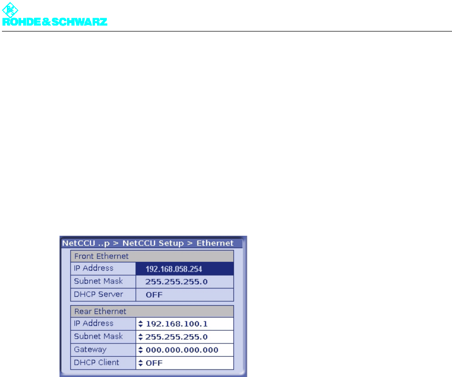
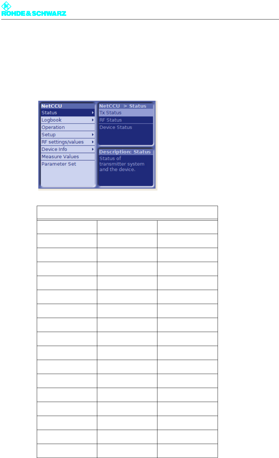
1. Select the NetCCU > Setup > NETCCU Setup > Ethernet menu from the front panel of
the NETCCU®.
Fig. 4 Entering the IP address
2. From the context menu, select the Edit Offline mode.
3. To determine the required IP address data automatically, select the ON switch position
from the Rear Ethernet part of the panel at DHCP Client.
or (for manual entry)
Select the OFF switch position from the Rear Ethernet part of the panel at DHCP Client
and enter the IP Address, Subnet Mask and Gateway parameters in their respective
parts of the panel.
4. From the context menu, select the Submit Changes entry.
The changes will be made.
Configuring the browser
Before you can operate the NETCCU® via your browser, the following conditions must be
satisfied:
– Setting of cookies must be enabled
– Scripting of Java Applets must be activated
– "Java Platform Standard Edition" must be installed and activated.
The next section uses Microsoft Internet Explorer to explain how you can check whether
these conditions have been met or what changes you need to make.

Chapter 5 Operating
2098.0594.72 - 5.6 - E-1
Note Please note that the settings described here need not necessarily match your current
browser settings one hundred percent.
All necessary changes and settings can be found in the Tools > Internet Options menu on
your Internet Explorer.
Checking and adapting the settings for cookies:
1. Select the Data Protection tab and click on the Default button if available.
2. Set the security level via the slider (right the way down) to Accept All Cookies.
Checking and adapting the settings for Java applets:
1. Select the Security tab.
2. For the Internet zone select the option Custom Level.
3. In the tree structure go to Scripting > Scripting of Java applets and select the Enable
option.
Installing Java (Sun) JRE if necessary; checking and adapting the settings
1. Select the Advanced tab.
2. Check whether the entry Java (Sun) JRE ... is present and enabled.
3. If necessary download "Java Platform Standard Edition" (including standard installation)
from the Sun web site "www.java.com".
4. Then select the Internet Explorer's Advanced tab again and check whether the software
is installed and enabled.
Starting the program
1. Start the browser on your PC or client.
2. Enter the same IP address as the one you entered on the NETCCU®. The Login screen
will appear.
ATTENTION!
Please note that the modified settings described here may adversely affect the security of
your Internet connections.
The following authorizations will be available to you:
Authorization Password
Calibration (authorization to calibrate trans-
mitter components, e.g. exciters)
1234
Configuration (authorization to set basic
transmitter parameters, e.g. Setup)
1234
Maintenance (authorization to perform main-
tenance tasks, e.g. software updates)
1234
Chapter 5 Operating
2098.0594.72 - 5.7 - E-1
3. Log in under the authorization you want and confirm with OK.
The appropriate input screen will appear.
1.2.2 Browser-Based Operation
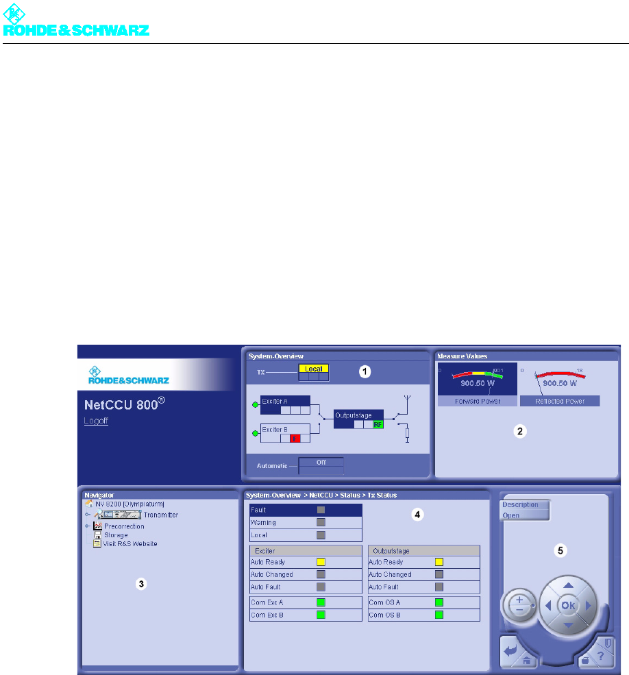
After you log on, the following entry screen will appear.
1) System Overview: current transmitter status
2) Measure Values: Display of the forward and reflected power
3) Navigator: display and navigation through the transmitter menus
4) System Overview ...: display of the menus selected in the navigator
5) Control panel: elements for navigating within the menu system and displaying and editing menu entries
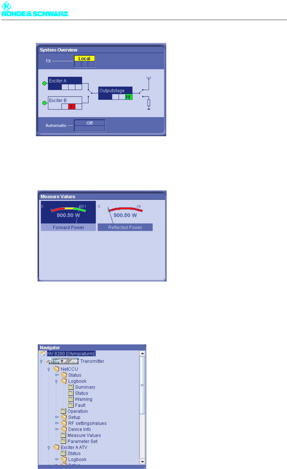
System Overview
The System Overview window provides an overview of the current status of the transmitter
and its components.
Operation (authorization to make settings
that directly affect transmitter operation)
1234
Query (read-only authorization) 1234
Chapter 5 Operating
2098.0594.72 - 5.8 - E-1
Measure Values
The current forward power and reflected power are displayed in the Measure Values win-
dow.
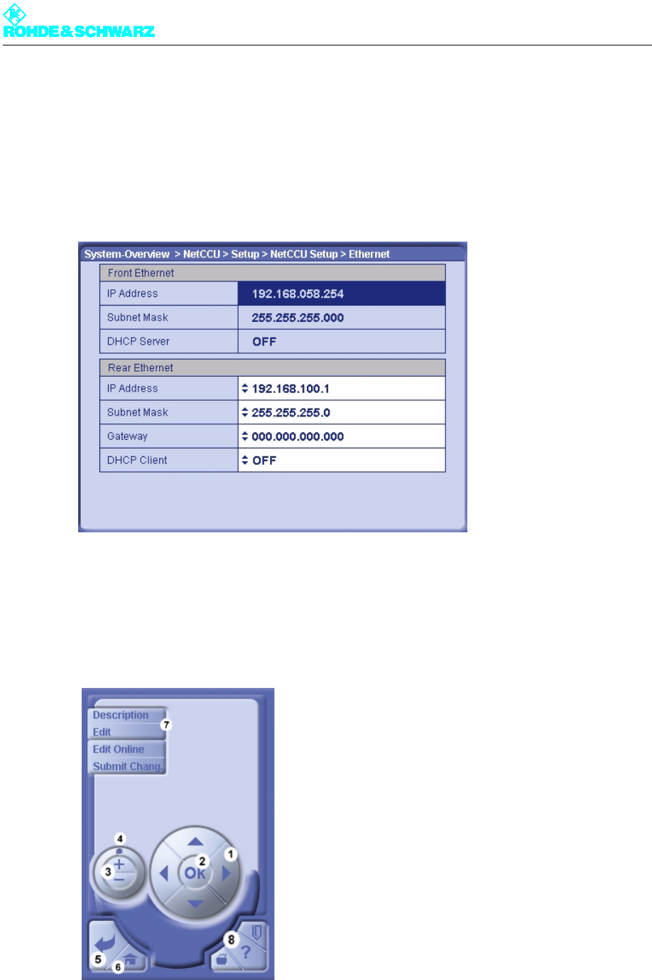
Navigator
The Navigator shows the menus of all system components. You can open the individual
folders or menus by double-clicking them with the mouse. The selected menus are dis-
played in the System Overview window (menu window).
Chapter 5 Operating
2098.0594.72 - 5.9 - E-1
1) Folder
2) Menu
System Overview (menu window)
The System Overview window (menu window) displays the menu selected from the Nav-
igator window.
1) Double-arrow symbol: Entry can be changed
Control panel
You can use the control panel to navigate within the menu structure and menus and change
settings. You can activate the individual control elements with the mouse or keyboard.
1) For switching between menu entries, accessing editable values and entering numeric values; each click of the
cursor keys (up/down) increments or decrements a number correspondingly
2) For editing (switch to edit mode) and confirming settings (corresponds to entry key on the keyboard)
3) Corresponds to up and down cursor keys (legend 2)

Chapter 5 Operating
2098.0594.72 - 5.10 - E-1
4) For quickly switching between menu entries, for quickly accessing editable values, and for quickly entering
numeric values
5) Primarily for taking one step back in the menu structure; also used to cancel settings that have not yet been
confirmed with OK
6) Return to home menu
7) For displaying context menus for current menu window (standard context menus: Description: help texts;
Open: opens menu or menu entry; Edit: for editing entry; Edit Offline: for editing entry without immediately in-
corporating change; Submit Change: entry edited offline is accepted in system)
8) Not enabled in this software version
Chapter 5 Operating
2098.0594.72 - 5.11 - E-1
2 NETCCU Menus
2.1 Overview of Menus
Menu Structure of the NETCCU®
Level 1 Level 2 Level 3
Status
Tx Status
RF Status
Device Status
Logbook
Summary
Status
Warning
Fault
Operation
Setup
TX Setup
NetCCU Setup
Common
SW Maintenance
Ethernet
Chapter 5 Operating
2098.0594.72 - 5.12 - E-1
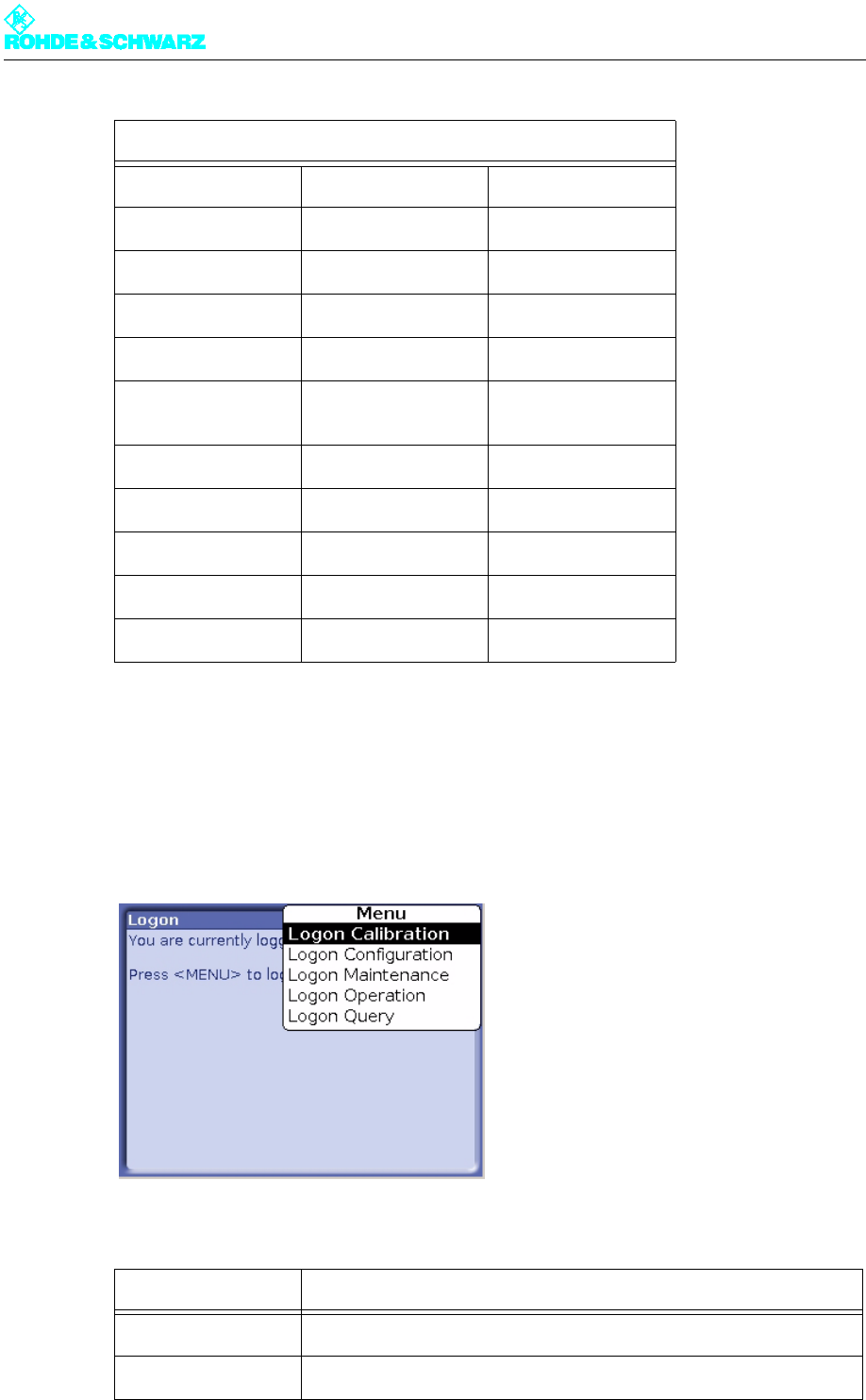
2.2 Login
Various authorization levels protect against nondeliberate access of critical system settings
from the home menu. You can change the authorization level from any menu by using the
CHANGE USER context menu.
The following levels are available:
SNMP
RF settings/values
RF Vision
RF Probe Forward
RF Probe Reflected
RF Probes Measure
Values
Device Info
NetCCU
Mainboard
Measure Values
Parameter Set
Authorization Description
Calibration Authorization to calibrate transmitter components, e.g. exciters
Configuration Authorization to set basic transmitter parameters, e.g. Setup
Menu Structure of the NETCCU®
Chapter 5 Operating
2098.0594.72 - 5.13 - E-1
Note To use the menus via the Web interface, you must enter the password "1234".
2.3 Status Menu
The Status menu provides an overview of faults, warnings and status messages relating to
the individual components and functions of the transmitter.
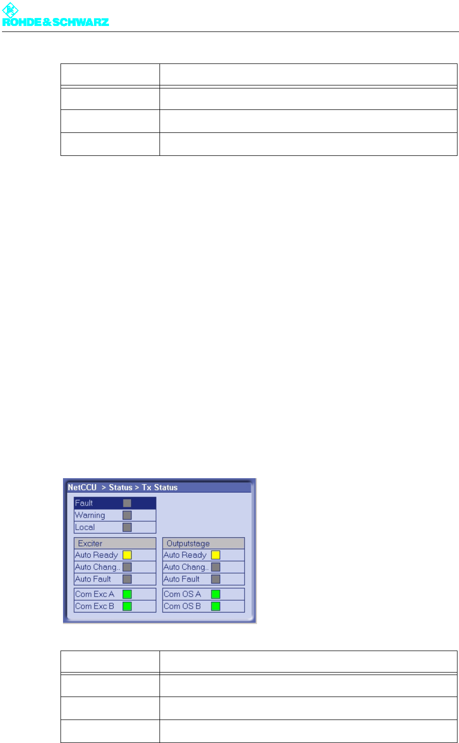
2.3.1 Tx Status Menu Window
The TX Status menu window provides an overview of faults, warnings and status messag-
es about the transmitter's communication and standby status.
The Logbook menu window is divided into three parts (reading from top left to bottom
right):
– General fault / local mode
– Exciter status messages
– Output stage status messages (rack/amplifier)
Maintenance Authorization to perform maintenance tasks, e.g. software updates
Operation Authorization to make settings that directly affect transmitter operation
Query Read-only authorization
Display Description
Fault Red: a fault has occurred in the transmitter system
Warning Yellow: the transmitter system has issued a warning message
Local Yellow: the NETCCU has been switched to local operation
Authorization Description

Chapter 5 Operating
2098.0594.72 - 5.14 - E-1
2.3.2 RF Status Menu Window
The RF Status menu window provides an overview of the transmitter's RF status.
Exciter
Auto Ready Green: the automatic exciter switchover unit is ready
Yellow: the automatic exciter switchover unit is not ready
Auto Chan. Yellow: switchover to the standby exciter has occurred; Auto Ready dis-
play shines yellow
Auto Fault Red: a fault occurred during switchover to the standby exciter
Comm Ex. A Red: communications error between NETCCU and exciter A
Comm. Ex. B Red: communications error between NETCCU and exciter B
Output stage
Auto Ready Green: the automatic amplifier switchover unit is ready
Yellow: the automatic amplifier switchover unit is not ready
Auto Chan. Yellow: switchover to the standby amplifier has occurred; Auto Ready
display shines yellow
Auto Fault Red: An error occurred during switchover to the standby amplifier.
Comm. OS. A Red: Communications error between NETCCU and exciter A
Comm OS. B Red: Communications error between NETCCU and exciter B
Display Description
RF OK Green: antenna output power above the warning threshold that has
been set
RF On Green: Antenna output power above the fault threshold that has been
set
Display Description
Chapter 5 Operating
2098.0594.72 - 5.15 - E-1
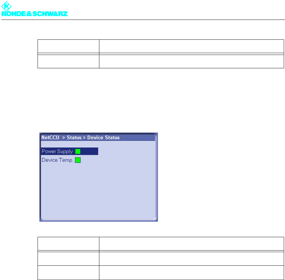
2.3.3 Device Status Menu Window
The Device Status menu window provides an overview of faults, warnings and status mes-
sages about the NETCCU®.
2.4 Logbook Menu
You can use the Logbook menu to query status and error messages about the NETCCU®.
The Logbook menu windows provide an overview of status messages, warning messages
and fault messages about the NETCCU®.
Note You can call up Logbook entries via the Summary, Status, Warning and Fault windows.
The structure of the four windows is identical.
Reduced RF Yellow: transmitter has reduced its output power
Display Description
Power Supply Red: internal power supply of the NETCCU failed; otherwise, green
Device Temp. Red: temperature inside the NETCCU too high; otherwise, green
Display Description
Chapter 5 Operating
2098.0594.72 - 5.16 - E-1
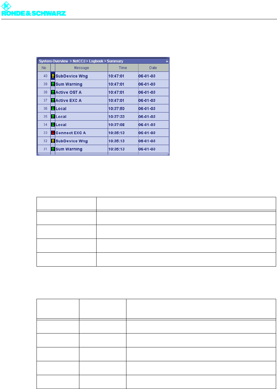
2.4.1 Summary Menu Window
Fig. 5 Logbook > Summary Window
The following table explains the meaning of the columns:
The arrows in the second column have the following meanings:
Column Description
No Consecutive entry number
Message Message
Time Time the message was received
Date Date the message was received
Arrow direc-
tion Arrow color Description
Up The event has just occurred.
Down The event is no longer current or relevant.
Red Fault
Yellow Warning
Green Status: In order

Chapter 5 Operating
2098.0594.72 - 5.17 - E-1
2.5 Operation Menu Window
You can use the Operation window to make settings for standby behavior and for the ex-
citer and amplifier.
Display Description
TX operation
Program On/Off On/off command for transmitter (exciter and output stage); corresponds
to the hard key on the front panel
Standby On/Off On/off command for standby transmitter
(all components that are not on an antenna)
Preselection
Exciter A/B Selection of the active exciter
Amplifier A/B Selection of the active amplifier
Automatic
Exciter On/Off Switches the automatic exciter switchover unit to active or not active
Ready Status of the automatic exciter switchover unit:
Green: Automatic switchover unit ready for operation
Yellow: Automatic switchover unit ready for operation
Changed Yellow: switchover to the standby exciter has occurred; Ready display
shines yellow
Output stage on/off
(only if passive output
stage standby = pas-
sive PA)
Switches the automatic amplifier switchover unit to active or not active
Ready Status of the automatic amplifier switchover unit:
Green: Automatic switchover unit ready for operation
Yellow: Automatic switchover unit not ready for operation
Changed Yellow: switchover to the standby amplifier has occurred; Ready display
shines yellow
Chapter 5 Operating
2098.0594.72 - 5.18 - E-1
2.6 Setup Menu
You can use the Setup menu to configure the transmitter system's hardware.
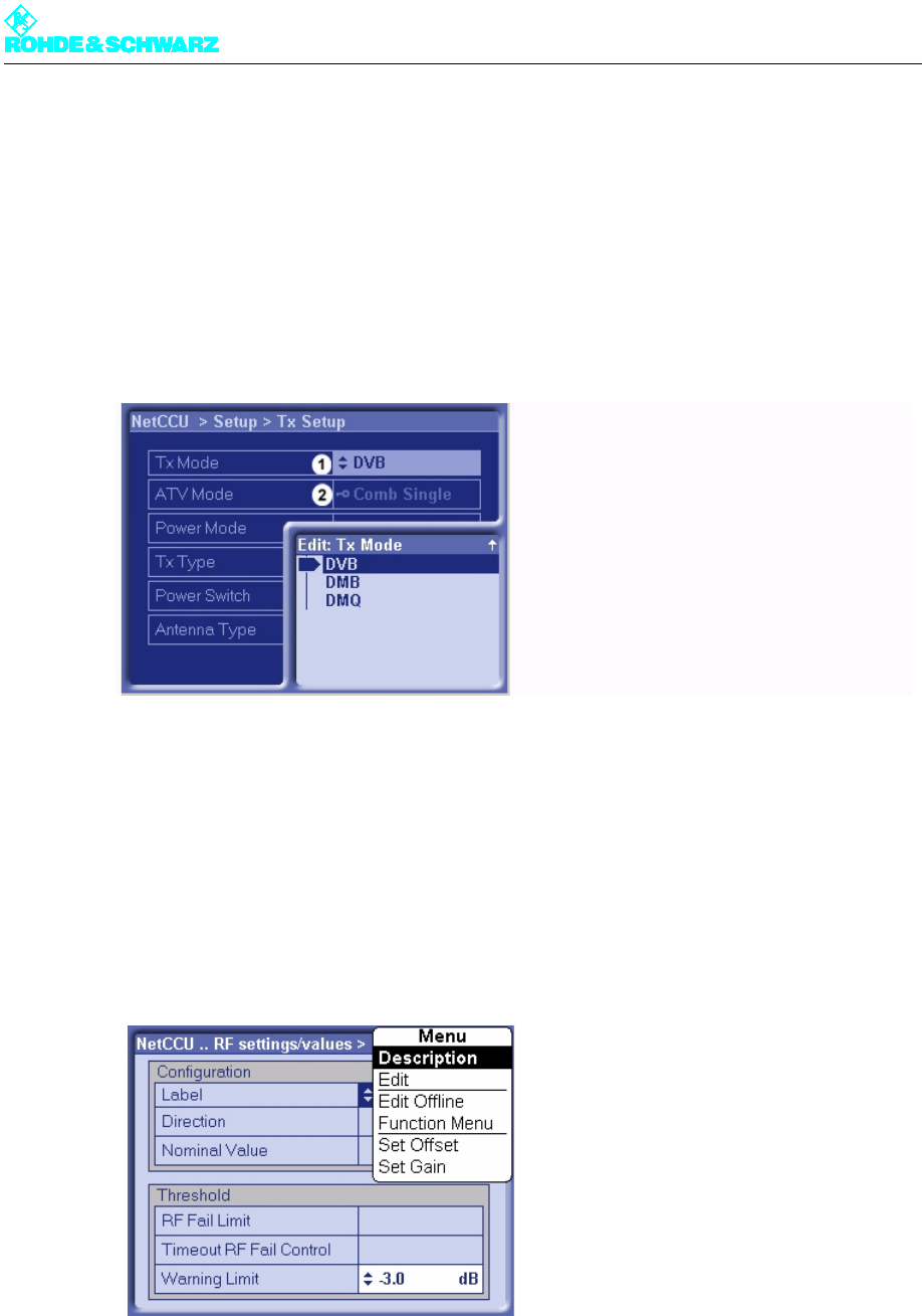
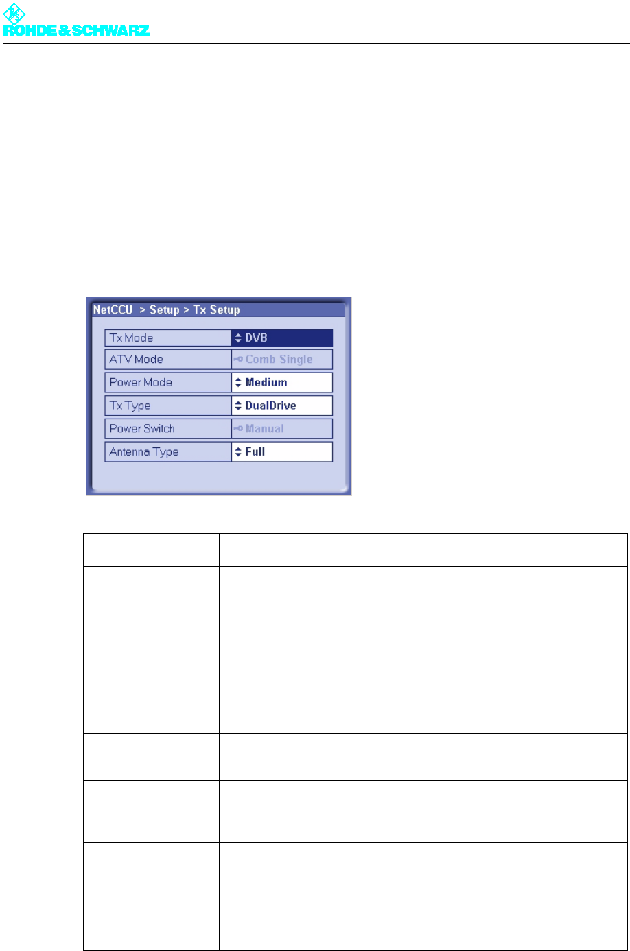
2.6.1 Tx Setup Menu Window
You can use the TX Setup menu window to define standby behavior and to make additional
system-specific settings.
Setting item Description
TX Mode Selection of the transmitter standard
– FM: analog sound broadcasting standard
– ATV: analoger TV standard
– DVB: digital TV standard
ATV Mode Selected only when setting ATV under TX Mode
– Comb Single: picture signal and sound signal are transmitted via one
amplifier (same channel) (single = 1 sound carrier)
– Comb Dual: picture signal and sound signal are transmitted via one
amplifier (same channel) (dual = 2 sound carriers)
Power Mode Setting for medium-power transmitters
– Medium
TX Type For setting the standby behaviour:
– Single TX: standby system (see below)
– Dual Drive: standby system (see below)
Power Switch Setting of the hardware configuration for antenna switchover. The fol-
lowing options are available:
– "Manual" for switching over the antenna manually
– "Automatic" for switching over the antenna electronically
Antenna Type Country-specific setting for the antenna type; the default setting is Full
Chapter 5 Operating
2098.0594.72 - 5.19 - E-1
Basic setting of the transmitter standby systems
2.7 NetCCU Setup Menu
You can make basic system settings in the NetCCU Setup menu.
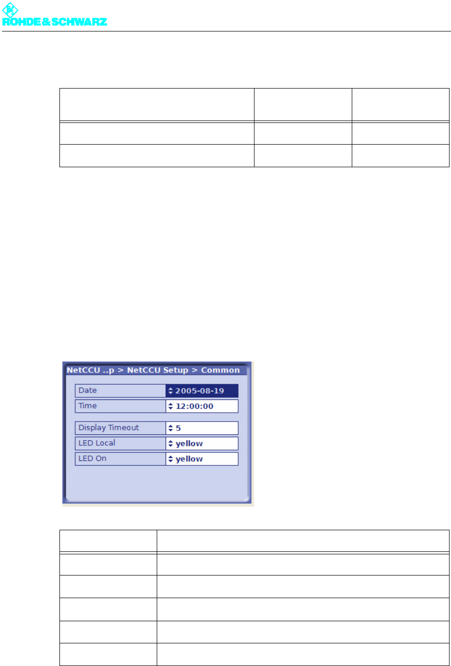
2.7.1 Common Menu Window
You make make general settings for the system in the Common menu window.
Transmitter standby system Setting: TX Type Setting: Power
Switch
Single transmitter system Single TX Manual
2 exciters / 1 amplifier stage Dual Drive Manual
Selection Description
Date Date
Time Local time
Display Timeout Time in minutes after which the display switches off (standby)
LED Local Color of the Local LED on the front panel of the NETCCU (yellow, green)
LED On Color of the On LED on the front panel of the NETCCU (yellow, green)
Chapter 5 Operating
2098.0594.72 - 5.20 - E-1
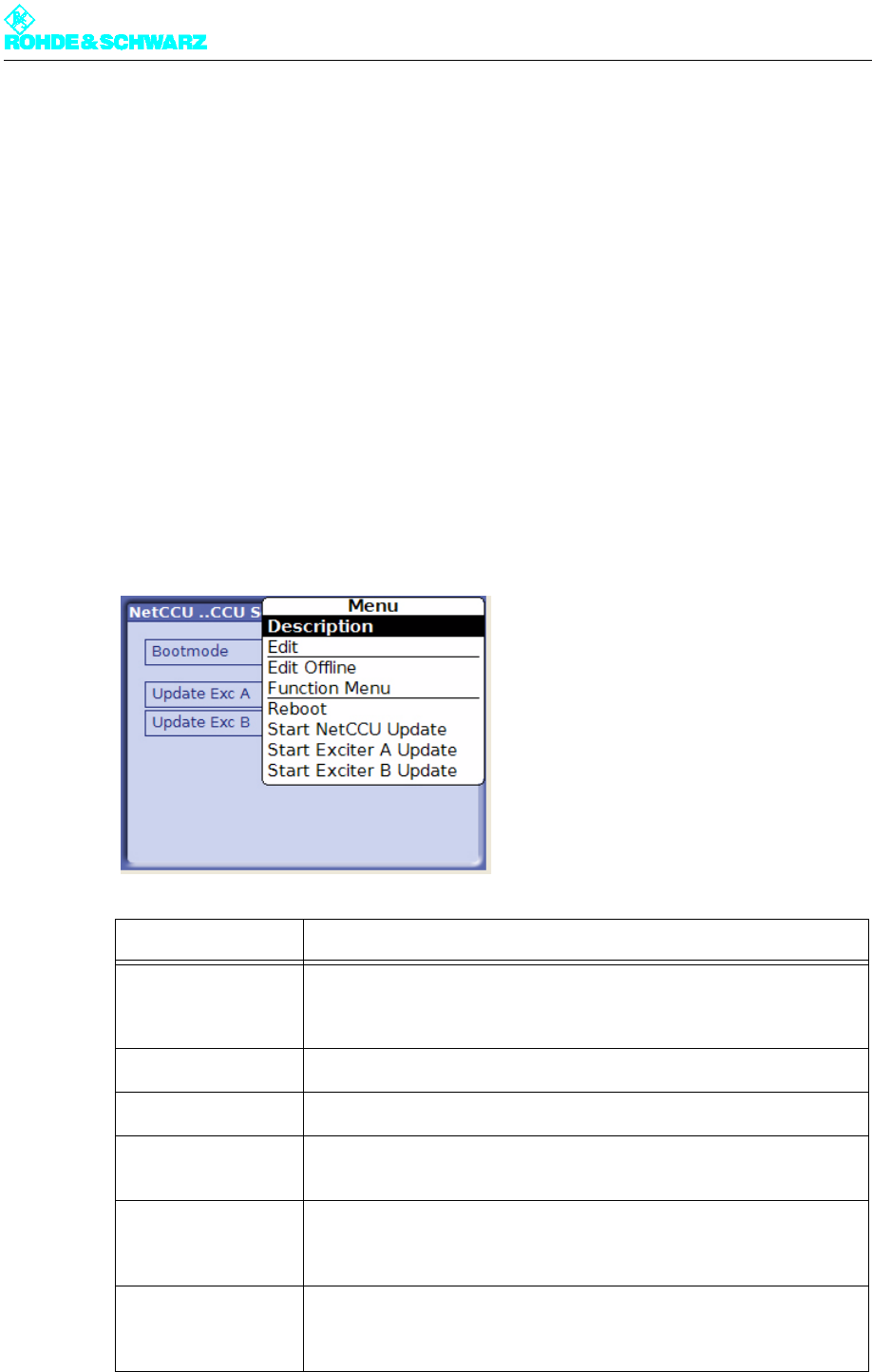
2.7.2 SW Maintenance Menu Window
You can use the SW Maintenance menu window to carry out software updates for the
NETCCU® and the connected exciter.
To perform a software update, you must connect the NETCCU® with a PC that contains the
required updates and update software.
Before you call the update software on the PC, the NETCCU® must be set to update mode
via the Start NetCCU Update context menu. After you call the update software on the PC,
the software automatically analyzes which updates must be installed. The update proce-
dure is started from the PC by means of the update software.
Updates for the NETCCU® are installed straight away. In a further step, updates for the ex-
citer(s) must be started from the NETCCU® via the Start Exciter A/B Update context
menu.
Note The whole update procedure is described in detail in the Maintenance section of the NET-
CCU® manual.
Selection/display Description
Boot mode Setting of the boot mode
– warm: for booting after a reconfiguration, for example; the NETCCU
boots using the parameters currently set
Update Exc A Display showing the progress of the software update installation
Update Exc B Display showing the progress of the software update installation
Start NetCCU Update
(context menu)
The available software updates for the NETCCU are installed.
Start Exciter A
Update (context
menu)
The available software updates for Exciter A are installed.
Start Exciter B
Update (context
menu)
The available software updates for Exciter B are installed.
Chapter 5 Operating
2098.0594.72 - 5.21 - E-1
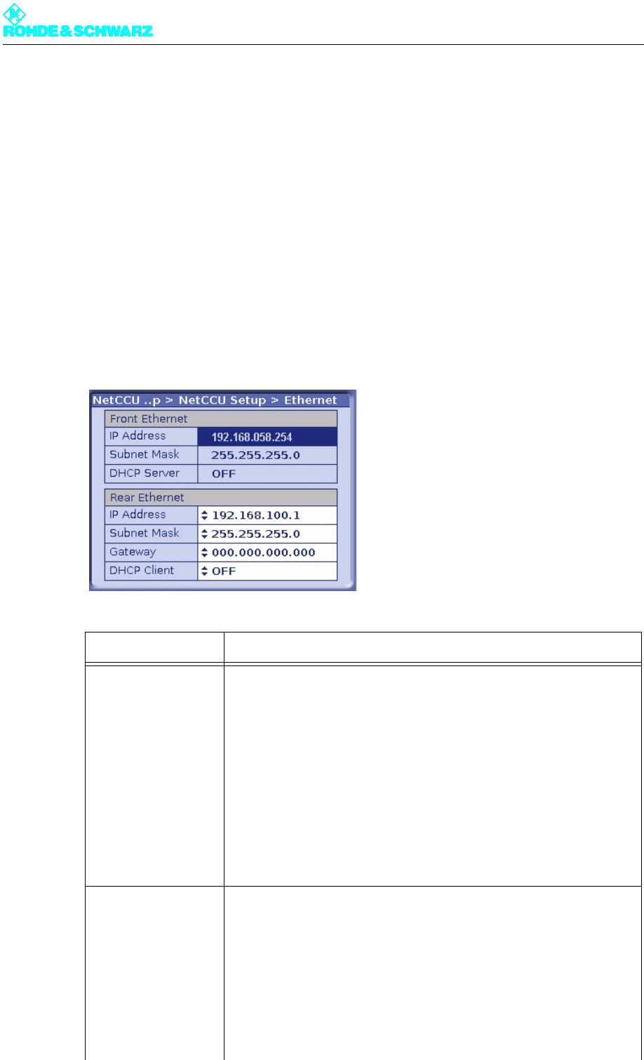
2.7.3 Ethernet Menu Window
You can use the Ethernet menu window to make the settings necessary for connecting the
NETCCU® in the following ways:
– to a PC or laptop via the Ethernet interface on the front panel (cross cable),
– to a LAN/WAN via the Ethernet interface on the rear panel.
The parameters for the front panel connectors are permanent settings; you can modify the
parameters for the rear connectors manually to suit your requirements or let them be deter-
mined automatically. The NETCCU® contains a DHCP client for automatically determining
the parameters.
Note To automatically determine the network data required for the rear-panel connection, a
DHCP server is must be present in the network.
Selection Description
Front Ethernet
IP Address The IP address (192.168.58.254) of the NETCCU is factory-set and can-
not be changed. To make an external connection to a PC/Laptop the
appropriate address must be entered: The first three segments (of the
above IP address) stay the same, but a value < 250 must be entered for
the last block of numbers.
Subnet mask The setting for the NETCCU subnet mask is factory-set and cannot be
changed. For an external connection, this same setting must also be
entered on a PC or laptop.
DHCP Server This function is not implemented in this version.
Rear Ethernet Manual settings should only be entered in Offline mode (context menu:
Edit Offline) and should then be activated by means of Submit Changes
(context menu).
IP Address Entry of a valid IP address. The IP address 192.168.058.254 is not to be
used.
Subnet mask The setting for the NETCCU subnet mask is factory-set, but can be
changed if necessary. For an external connection, this setting must be
defined in the network.
Chapter 5 Operating
2098.0594.72 - 5.22 - E-1
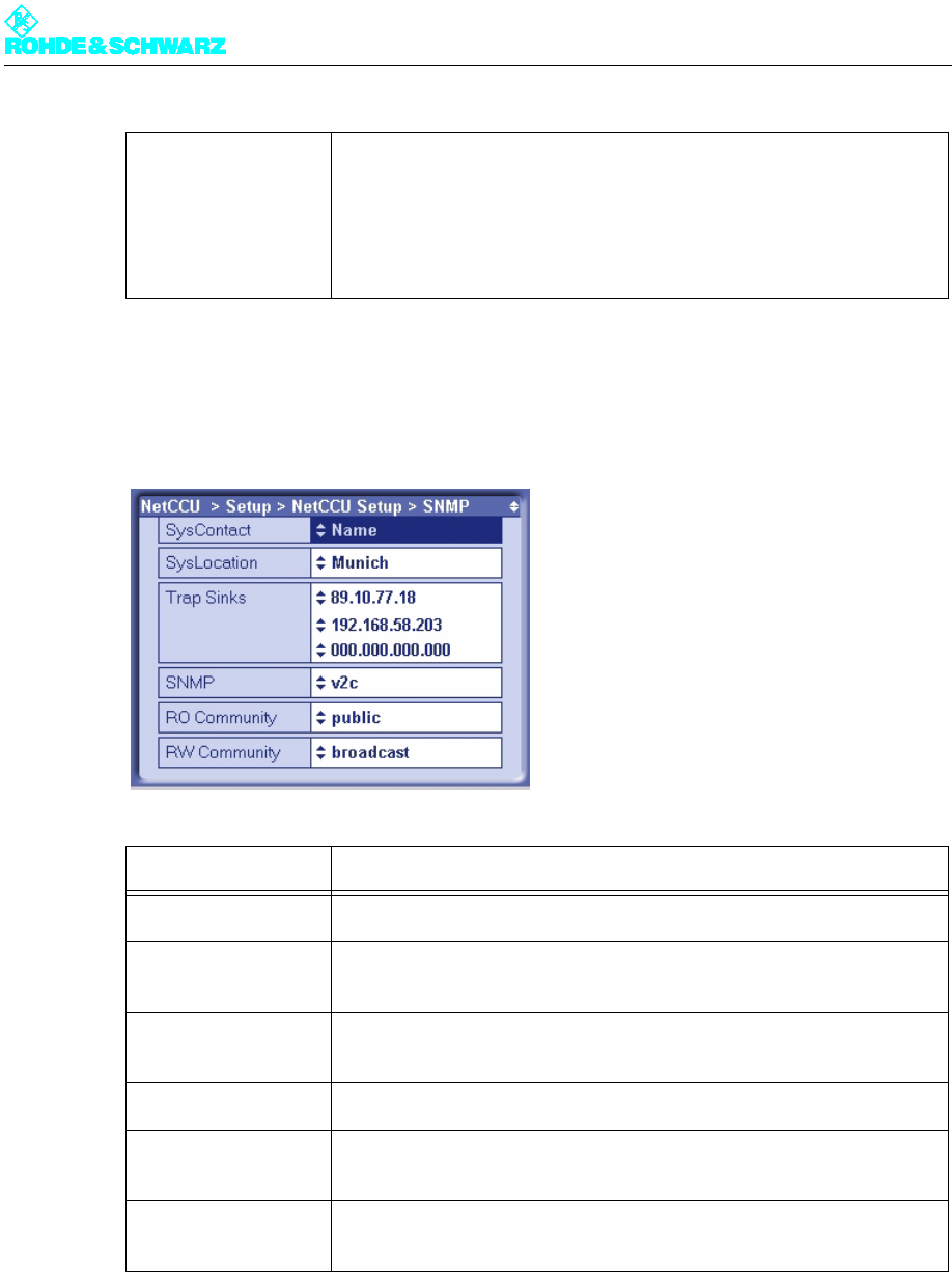
2.7.4 SNMP Menu Window
You can use the SNMP menu window to configure the SNMP connection.
2.8 RF settings/values Menu
You can use the RF settings/values menu to enter and read results for the transmitter sys-
tem, the standby system and the output power.
Gateway Entry of a gateway address (assigned by the network administrator).
DHCP Client ON: The IP address is automatically retrieved from the net.
OFF: The IP address has to be entered manually (see above).
Display Description
SysContact Name (e.g. the last name of a contact person)
SysLocation Location of the transmitter equipment that will be addressed via NetLink
(e.g. a town or city)
Trap Sinks The IP address (e.g. 89.10.63.43) to which traps will be sent if a fault
occurs on the transmitter
SNMP version The SNMP version in use (e.g. SNMP1)
Read Only Commu-
nity
Public (default setting); term and values can be replaced
Read Write Commu-
nity
Broadcast (default setting); term and values can be replaced
Selection Description
Chapter 5 Operating
2098.0594.72 - 5.23 - E-1
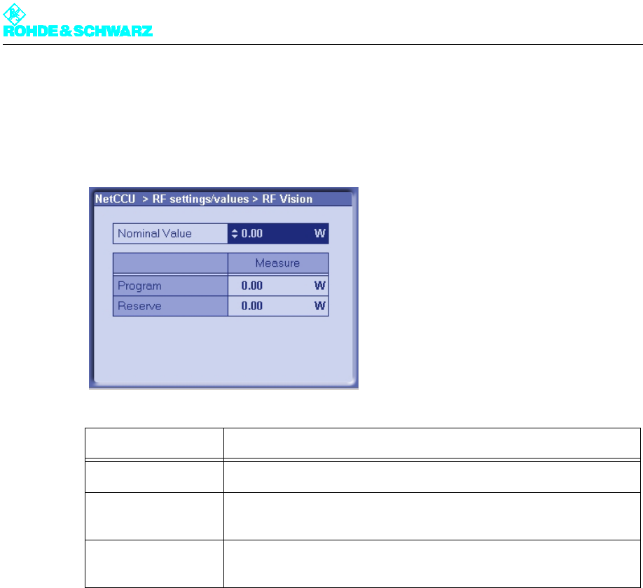
2.8.1 RF Vision Menu Window
You can use the RF Vision menu window to enter the nominal value for the picture forward
power.
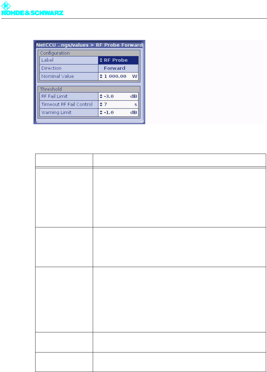
2.8.2 RF Probe Forward Menu Window
You can use the RF Probe Forward menu window to define the nominal values for the out-
put power and to define the lowest level of deviation at which error messages are to be out-
put. Two test points are available for measuring the RF power (RF Probe Forward and RF
Probe Reflection). Each test point has two RF rectifiers so that you can measure both the
forward and reflection power. In principle the forward power is measured with the aid of the
first test point (RF Probe Forward).
The left window of the NETCCU® status screen shows the forward power and the right win-
dow shows the reflection power, in accordance with the values entered here.
Entry/display Description
Nominal Value Entry of the nominal value for picture forward power
(Measure) Program Current output power at the antenna test point of the active transmitter
system (output stage)
(Measure) Reserve Current output power at the antenna test point of the standby transmitter
system (output stage)
Chapter 5 Operating
2098.0594.72 - 5.24 - E-1
Note You can calibrate the measuring system and the zero point via the context menu.
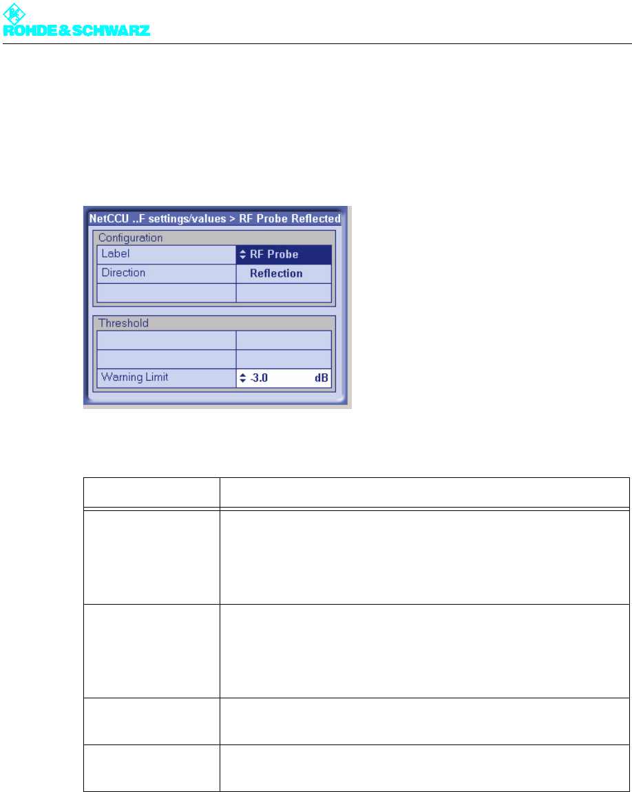
2.8.3 RF Probe Reflected Menu Window
You can use the RF Probe Reflected menu window to define the nominal values for the
output power and to define the lowest level of deviation at which error messages are to be
output. Two test points are available for measuring the RF power (RF Probe Forward and
Entry/display Description
Configuration Defining and setting a nominal value for forward power
Label User-defined name for the "RF Probe" test point
Direction Display of signal direction (forward power)
Nominal Value Entry of the nominal value, determined if necessary my external mea-
surement of the forward power
Threshold Setting upper and lower thresholds for forward power; warnings and
error messages are issued if these thresholds are crossed.
RF Fail Limit Selection of a dB value at which a fault message will be output if power
drops below it
Timeout RF Fail Con-
trol
Selection of the duration of the violation of the lower threshold of the for-
ward power specified under RF Fail Limit at which an error message will
be output. For example, if a value of 3 dB has been entered under FR
Fail Limit and the actual value falls below that level for 8 seconds (exam-
ple setting for Timeout for RF Fail Control), an error message will be out-
put
Warning Limit Selection of a dB value for forward power at which a warning message
will be output if power drops below it
Set Gain (Context
Menu)
Calibration of the internal measuring system. The internal result for the
entered (measured) nominal value can be stored by selecting Set Gain.
Set Offset (Context
Menu)
Calibration of the zero point at which the externally measured power is
displayed. The zero point is calibrated by selecting Set Offset.
Chapter 5 Operating
2098.0594.72 - 5.25 - E-1
RF Probe Reflection). Each test point has two RF rectifiers so that you can measure both
the forward and reflection power. In principle the reflected power is measured with the aid
of the second test point (RF Probe Reflection).
The left window of the NETCCU® status screen shows the forward power and the right win-
dow shows the reflection power, in accordance with the values entered here.
Note You can calibrate the measuring system and the zero point via the context menu.
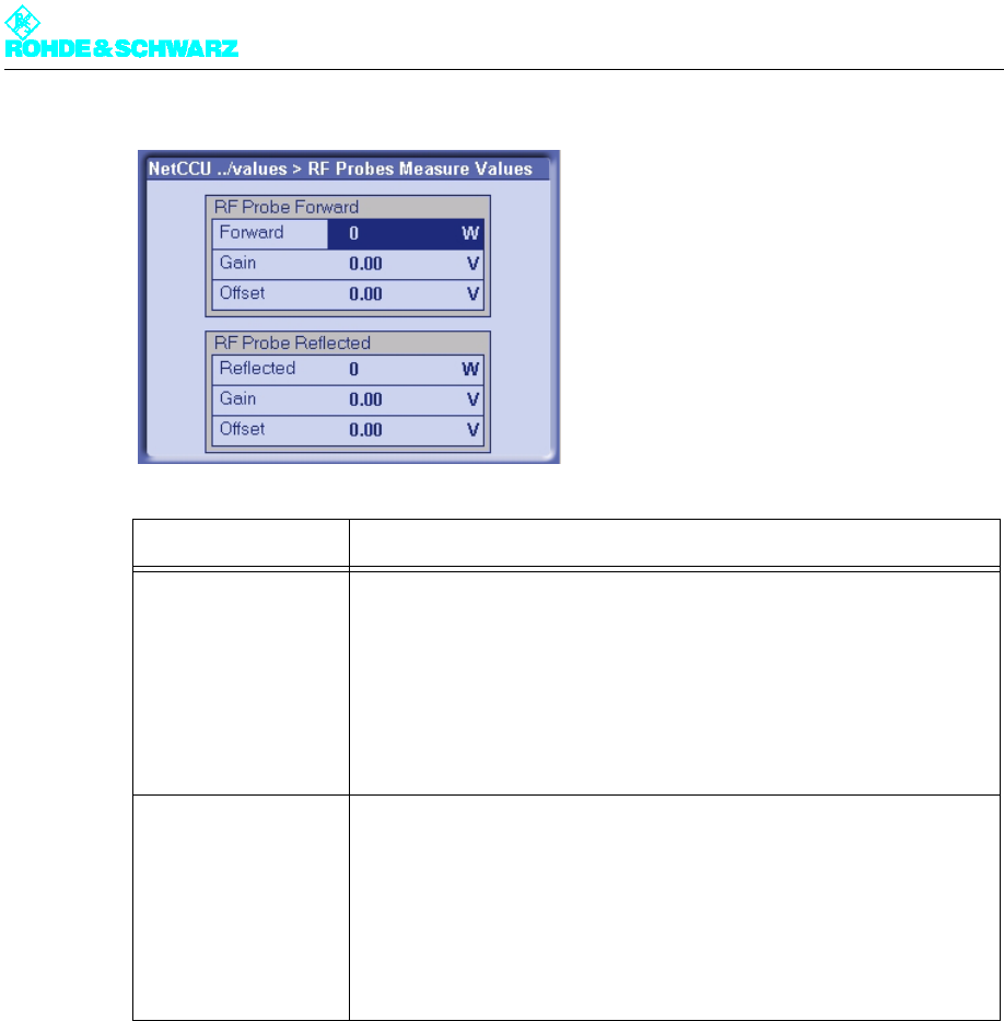
2.8.4 RF Probes Measure Values Menu Window
The RF Probes Measure Values menu window displays the values set in the RF Probe
Forward/Reflection menu window.
Entry/display Description
Configuration Defining and setting a nominal value for reflected power.
Label User-defined name for the "RF Probe" test point
Direction Display of signal direction (reflected power)
Threshold Setting of upper and lower thresholds for forward/reflection power at
which warning and error messages are output if they are crossed.
Warning Limit Selection of a dB value at which a warning message will be output if
power drops below it
Set Gain (Context
Menu)
Calibration of the internal measuring system. The internal result for the
entered (measured) nominal value can be stored by selecting Set Gain.
Set Offset (Context
Menu)
Calibration of the zero point at which the externally measured power is
displayed. The zero point is calibrated by selecting Set Offset.
Chapter 5 Operating
2098.0594.72 - 5.26 - E-1
2.9 Device Info Menu
You can use the Device Info menu to display detailed product information about any hard-
ware or software component of the NETCCU®.
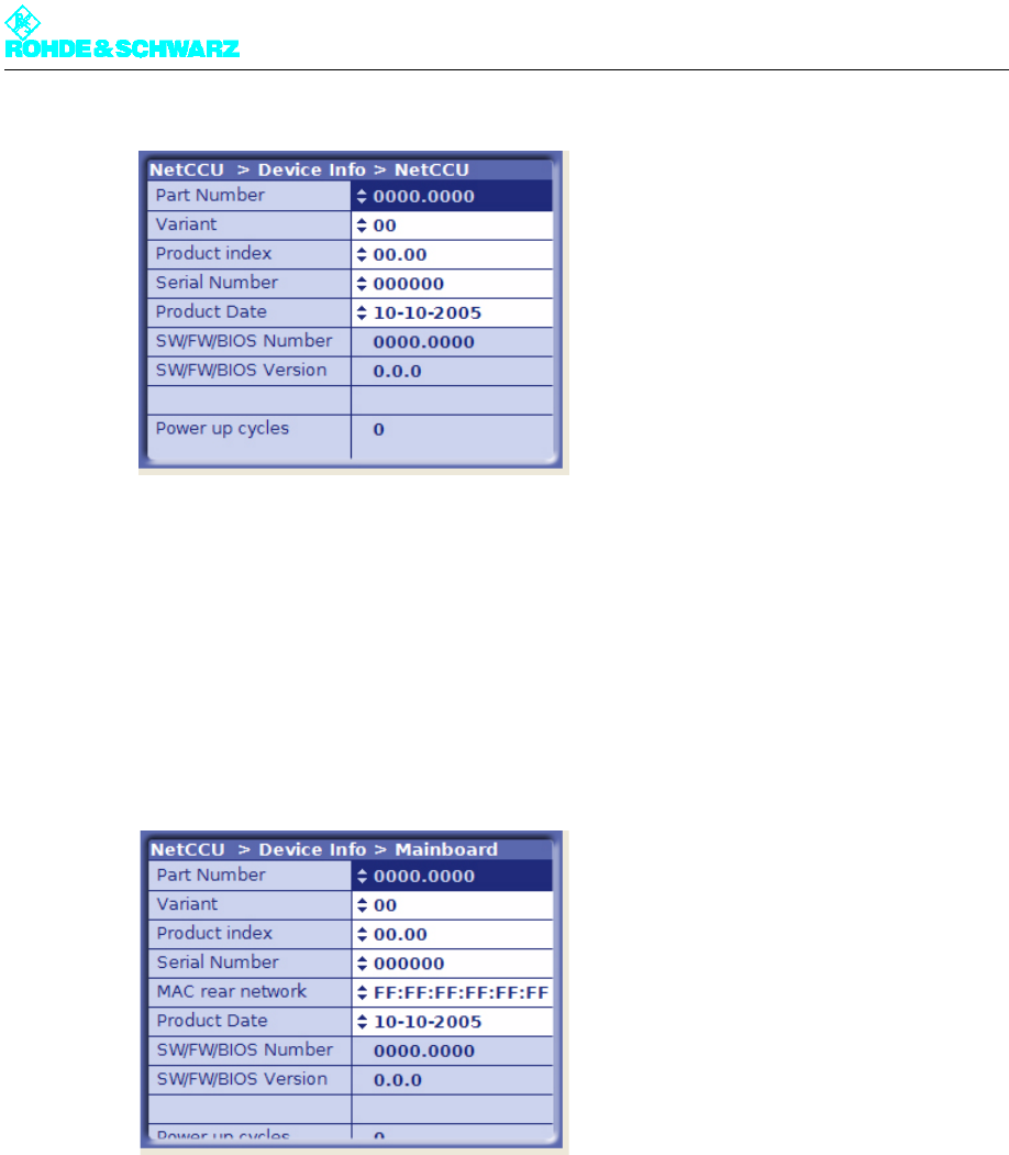
2.9.1 NetCCU Menu Window
The NetCCU menu window gives you general information about the NETCCU® hardware
and software.
Display Description
RF Probe Forward Values for antenna test point 1 (forward power)
Forward Measured forward power (output power at the antenna)
Gain Internal result corresponding to the measured output power
Offset Internal value starting at which the externally measured forward power is
displayed.
RF Probe Reflected Values for antenna test point 2 (reflection power)
Reflected Measured reflection power
Gain Internal result corresponding to the measured reflection power
Offset Internal value starting at which the externally measured reflection power
is displayed.
Chapter 5 Operating
2098.0594.72 - 5.27 - E-1
Context menu
The context menu provides additional information about the specific component.
2.9.2 Mainboard Menu Window
The Mainboard menu window gives you general information about the hardware and soft-
ware on the NETCCU® motherboard.
Context menu
The context menu provides additional information about the specific component.
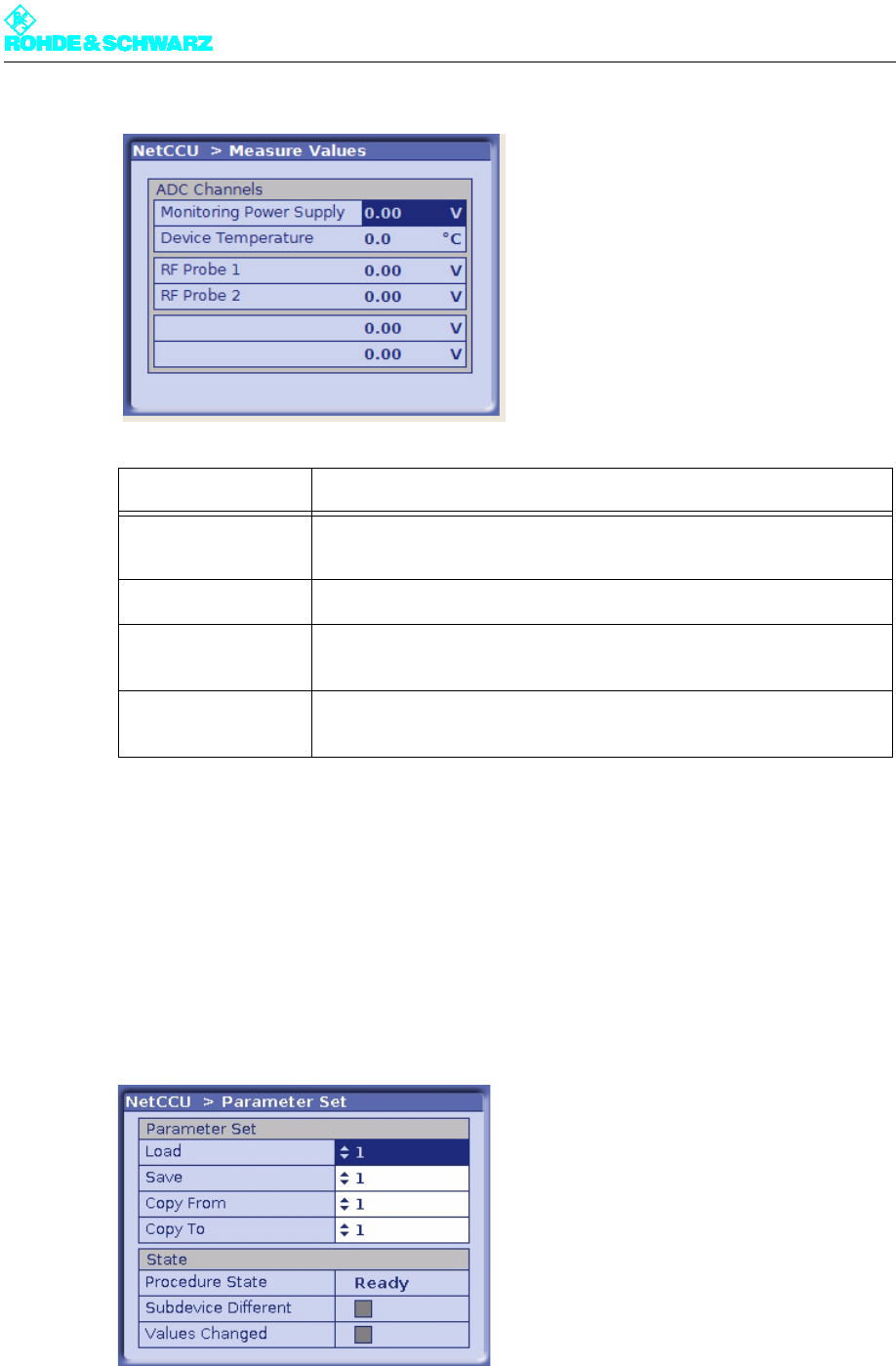
2.10 Measure Values Menu Window
The Measure Values menu window displays the current results for the transmitter test
points.
Chapter 5 Operating
2098.0594.72 - 5.28 - E-1
2.11 Parameter Set Menu Window
You can use the Parameter Set menu window to create, load and save parameter sets for
the settings in the NETCCU and the components it controls. Then if the operating environ-
ment changes (e.g. there is a change of frequency) you can access complete parameter
sets instead of having to set each individual value. You have eight memory locations avail-
able in addition to the current memory location (i.e. the parameter set currently loaded).
Display Description
Monitoring Power
Supply
Internal voltage value of the NETCCU power supply
Device Temperature Internal temperature of the NETCCU
RF Probe 1 Voltage of the internal result for the output power at antenna test point 1
(forward power)
RF Probe 2 Voltage of the internal result for the output power at antenna test point 2
(reflection power)

Chapter 5 Operating
2098.0594.72 - 5.29 - E-1
Entry/display Description
Parameter Set
Load Selecting a parameter set as the current parameter set; the currently
loaded parameter set acts as an independent copy of the stored param-
eter set.
Save Saving the current (and in some cases newly defined) parameter set at
the selected memory location.
Copy From Selecting a parameter set that you wish to save to another memory loca-
tion. This procedure should only be carried out in Offline mode (context
menu: Edit offline).
Copy To Selecting a memory location to which you wish to copy the parameter
set selected (i.e. copied) above. This procedure should only be carried
out in Offline mode (context menu: Edit offline). Having completed the
procedure, implement any changes via the context menu (Submit
changes).
State
Procedure State Display showing the status of the action that is being carried out (Ready,
Loading, Saving, Copying)
Subdevice Different Yellow: One of the transmitter components controlled by the NETCCU
contains set values that differ from the parameter set that is currently
set.
Values Changed Yellow: The values in the current parameter set no longer agree with
those in the stored original.
Context menu
Reload This reloads the parameter set selected at Load as the current parame-
ter set (current values are overwritten).
Resave This saves the current parameter set again at the memory location
selected at Save (the values already stored at this memory location are
overwritten).
Recopy This is a repetition of the "Copy From / Copy To" procedure. The values
at the memory location to which the copied parameter set is written are
overwritten.
Save Changes Changes made to the current parameter set are saved.
Chapter 5 Operating
2098.0594.72 - 5.30 - E-1
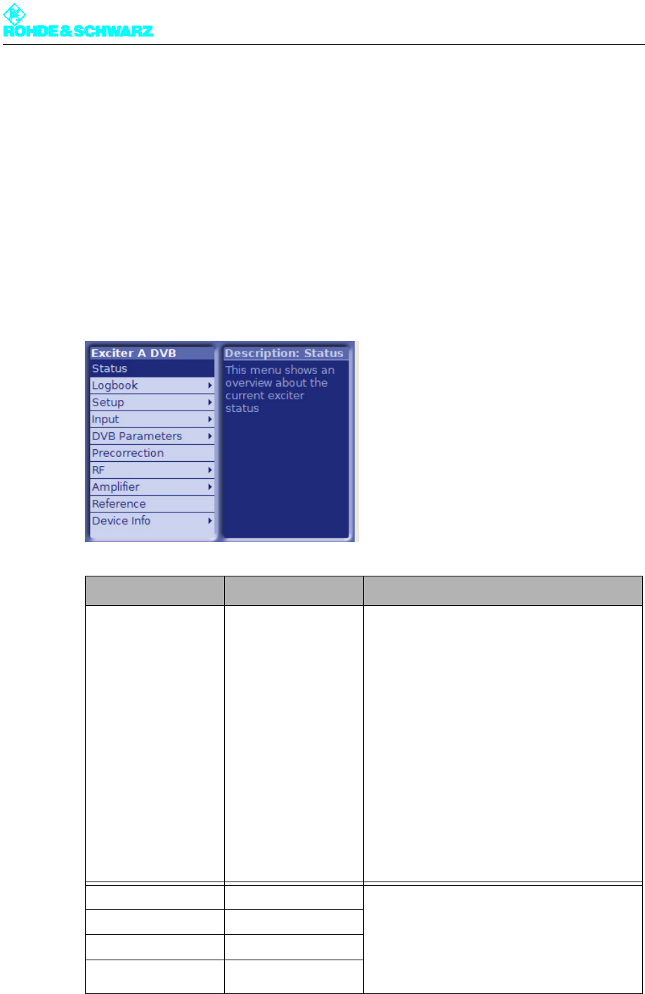
3 Exciter A/B Menus
You can use the Exciter A/B menus to operate and configure the exciter concerned and to
call up information.
Note The Exciter B menus and menu windows are identical to the Exciter A menus and menu
windows.
3.1 Overview of Menus
Level 1 > Level 2 / 3> Parameters
Status > Displays:
– Sum Fault
–RF
– Exciter On
– Loop
– Input OK
– Input 1 connect
– Input 2 connect
– Reference
–1 PPS
–Sum Warning
– Output open
–Board Error
– Temperature
–Fan
– Active Input
– Wrong Datarate
–Mute
–Test
Logbook > Summary > Logged information:
–No
– Message
–Time
–Date
– Set or reset
(for warnings and error messages only)
Status >
Warning >
Fault >

Chapter 5 Operating
2098.0594.72 - 5.31 - E-1
Setup > DVB > Setting items:
– Digital Standard
– Network Mode
– TPS Source
– Cell ID Enable
– TX Address
– TX Automatic
– Amplifier Control
Input > Input Config HP > Setting items for Input HP 1 or Input HP 2 as appropri-
ate:
– Presel. Mode
Displays for Input HP 1 or Input HP 2 as appropriate:
– Packet Length
– Meas. Data Rate [bps]
– Req. Data Rate [bps]
–Active Mode
Input > Input Config LP > Displays for Input LP 1 or Input LP 2 as appropriate:
– Presel. Mode
Displays:
– Packet Length
– Meas. Data Rate [bps]
– Req. Data Rate [bps]
–Active Mode
Input > Input Automatic > Setting items:
– Preselect Input
–Autoswitch
–Seaml. Switching
–Priority
– Check Time Forward
– Check Time Back
– On Input Fail
Displays:
– Seamless switching
DVB Parameters > TPS > Setting item
– TPS Source
Displays: Active / Setting items: Manual:
– Bandwidth
– FFT Length
– Guard Interval
– Constellation
– Alpha
–Cell ID
– Interleaver
– Code Rate [HP/LP]
– Time Slicing [HP/LP]
– MPE FEC [HP/LP]
Display: Active
– Req. Data Rate [HP/LP]
DVB Parameters > SFN Delay > Setting items:
–Static Delay
– Max Leap in Time
Displays:
– Processing Delay
– Dynamic Delay
– Network Delay
– TX Offset Delay
– Maximum Delay
– Total Delay
Level 1 > Level 2 / 3> Parameters

Chapter 5 Operating
2098.0594.72 - 5.32 - E-1
DVB Parameters > Test Signals > Setting items:
–PRBS Insertion
– Test Signal Insertion
– Carrier 1
– Carrier 2
Precorrection > Setting items:
– Nonlinear Correction
– Amplitude
– Phase
– Nonlinear Frequency
– Point 1
– Point 2
– Linear Correction
– Amplitude
– Group Delay
RF > Synthesizer > Setting items:
– Frequency
– Frequency Offset
– Reference
–OCXO Adjust
RF > Output > Setting items:
– RF Output
– Regulation
– Manual RF Level
– Output Attenuation
– RF Slope
– Modulation Slope
Displays:
– AGC Regulation
RF > IQ Adjust > Setting items:
– I/Q Testsignal
– Bias Coarse [I/Q]
– Bias Fine [I/Q]
– Gain [I/Q]
–Phase
Displays:
– Auto I/Q Adjust
– LO1 Frequency
Reference Setting items
– Reference
–OCXO Adjust
– Mute on PPS Fail
– Mute on Ref. Fail
–Fail Delay Time
Device Info > Exciter > Displays:
– Part Number
– Variant
– Product index
– Serial Number
– Product Date
– Software Number
– Software Version
– Operating hours
– Power up cycles
Level 1 > Level 2 / 3> Parameters
Chapter 5 Operating
2098.0594.72 - 5.33 - E-1
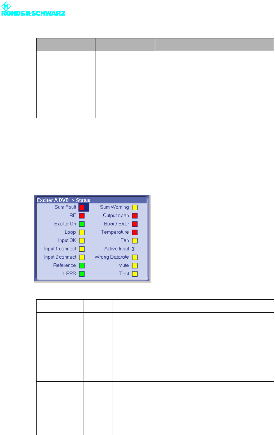
3.2 Status Menu
The Status menu summarizes the current status of the exciter. Color coding (green, yellow
and red) is used to indicate status information, warnings and error messages. In addition,
some basic settings are shown.
Device Info > Boards > Displays:
– Part Number
– Variant
– Product index
– Serial Number
– Product Date
– BIOS Version (mainboard only)
– Operating hours
– Power up cycles
Mainboard >
Input Interface >
RF Board >
Synth 1 >
Synth 2 >
Display/LED Color Description
Sum Fault Red Sum Fault: One or more errors occurred
RF Green The RF level at the exciter output is OK
Red There is no RF level at the exciter output even though the RF
output is enabled
- OFF - There is no RF level at the exciter output since the RF output is
not enabled ("manually" disabled)
Exciter On Green The RF output of the exciter is enabled
There are several options for enabling the RF output:
– In the RF menu with the RF Output setting item
– On the NETCCU® using the ON button
– On the exciter using the ON button (if there is no NETCCU® or
it is inactive)
Level 1 > Level 2 / 3> Parameters

Chapter 5 Operating
2098.0594.72 - 5.34 - E-1
Loop Yellow RF protective loop not closed
Green RF protective loop closed
Input OK Green Valid transport stream present on the active input
In the case of hierarchical coding the input is OK if valid transport
streams are present on both active inputs for HP Stream and LP
Stream.
Yellow Invalid transport stream on the active input
Input 1 connect Green – Input signal present on input TS 1 IN or
–In the case of hierarchical coding: Input signal present on
TS 1 IN (HP Stream) and TS 2 IN (LP Stream)
- OFF - – No input signal on input TS 1 IN
–In the case of hierarchical coding: No input signal on TS 1 IN
and/or no input signal on TS 2 IN
Input 2 connect Green – Input signal present on input TS 3 IN or
–In the case of hierarchical coding: Input signal present on
TS 3 IN (HP Stream) and TS 4 IN (LP Stream)
- OFF - – No input signal on input TS 3 IN
–In the case of hierarchical coding: No input signal on TS 3 IN
and/or no input signal on TS 4 IN
Reference Green External reference frequency present and OK
- OFF - External reference frequency not present or not OK
1 PPS Green External 1-PPS source present and the internal signal process-
ing is synchronized with the 1 PPS
- OFF - External 1-PPS source not present or the internal signal process-
ing is not synchronized with the 1 PPS
Sum Warning Yellow One or more warnings are active
Out Open Red The cable-break sensor has reported that the RF output is not
terminated.
HW Error Red A hardware error occurred in one or more modules of the exciter
Temperature Red At least one module is overheating
Fan Yellow A fan has failed; overheating can possibly occur
Red Both fans failed; there is a high risk of overheating
Wrong Datarate Yellow Wrong data rate on the active input
In the case of hierarchical coding the LED is illuminated if an
incorrect data rate is present on the active input for the HP
Stream and/or on the active input for the LP Stream.
Mute Yellow Output signal from signal processing disabled
Display/LED Color Description

Chapter 5 Operating
2098.0594.72 - 5.35 - E-1
3.2.1 Status Displays, Warnings and Error Messages
Signal colors and their meaning
When warnings and error messages occur, this usually means that transmission operation
is impaired. Different signal colors are used to distinguish the severity of an impairment or
the "quality" of the defect. The following applies:
Green......................................There is no impairment.
Yellow .....................................Although the exciter is functional, it is possible that external
influences are disrupting transmission operation.
Red .........................................A severe error has occurred so that transmission operation
is generally impossible.
Indications with and without memory effect
Status displays (green) and warnings (yellow) always reflect the current status of the excit-
er. On the other hand, error messages (red) remain active even after the reason for the error
has passed or the error has been corrected. If the error has been corrected, you can reset
the error display with the RESET key.
3.3 Logbook Menu
The logbook is used to record state changes (events) affecting the exciter.
The menu windows
The Logbook menu leads to the following menu windows:
Test Yellow Exciter is set to test mode
Display Status Description
Active Input 1 / 2 Display of the currently active input
In the case of non-hierarchical coding:
–1 = TS 1 IN
–2 = TS 3 IN
In the case of hierarchical coding:
–1 = TS 1 IN (HP Stream) + TS 2 IN (LP Stream)
–2 = TS 3 IN (HP Stream) + TS 4 IN (LP Stream)
Display/LED Color Description

Chapter 5 Operating
2098.0594.72 - 5.36 - E-1
–Summary: Complete logbook with all recorded data
–Status: Partial logbook with recorded status changes
–Warning: Partial logbook with recorded occurrences of warnings
–Fault: Partial logbook with recorded occurrences and resets of error messages
3.3.1 Logbook > Summary/Status/Warning/Fault
The complete logbook and the partial logbooks are uniformly structured. The messages are
numbered sequentially and contain the following information:
– Indicator for the occurrence × or disappearance Ø of an event (only for warnings or error
messages)
– Message: Brief description of the event
– Time: Time of day of the event
– Date: Date of the event
3.3.2 Logbook Contextual Menu
Additional contextual functions are available in the menu windows for the complete logbook
and the partial logbooks:
Function Description
Clear logbook Clears all entries in the current logbook. Note that it is not possible to
clear individual entries.
When you clear the complete logbook, the partial logbooks are also
cleared.
Restore logbook Restores the cleared entries in the current logbook.
When you restore the complete logbook, the partial logbooks are also
restored.
Chapter 5 Operating
2098.0594.72 - 5.37 - E-1
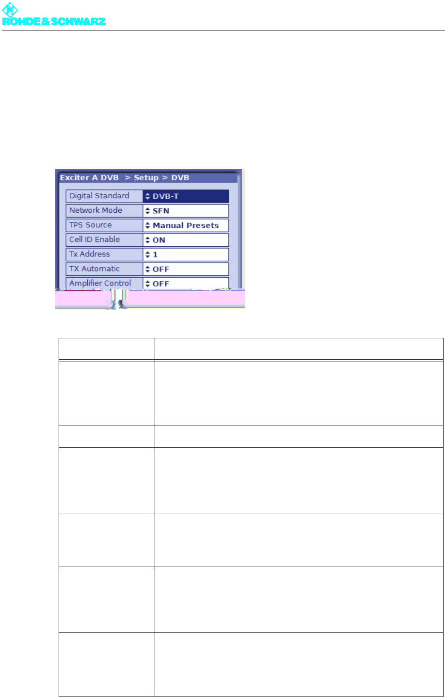
3.4 Setup Menu
3.4.1 Setup > DVB
The DVB menu window is used to enter the basic settings for signal processing.
Setting item Description
Digital Standard Selection of the digital TV standard: DVB-T, DVB-H or ATSC
Switching over from DVB-T or DVB-H after ATSC is followed by a
restart. At the same time signal processing is switched over and the
associated user interface is loaded.
Network Mode Selection of the network operating mode: SFN or MFN
TPS Source Setting the source for the TPS parameters: MIP or manual presets (see
section "DVB Parameters > TPS")
The TPS source can also be set in the DVB Parameters > TPS menu
window.
Cell ID Enable Switching cell ID signaling on or off in the TPS
The cell ID itself is set in the DVB Parameters > TPS menu window. It
can also be retrieved from the MIP.
Tx Address Setting the transmitter address; address range: 0 to 65535
Setting the transmitter address is a precondition to reading Tx informa-
tion (transmitter-specific settings) from the MIP. However, the informa-
tion is only used if Tx Automatic is enabled.
Tx Automatic Activates and deactivates Tx Automatic
When the automatics are enabled (and the transmitter address is set)
the following Tx parameters are retrieved from the MIP:
Time Offset, Frequency Offset and Cell ID
Chapter 5 Operating
2098.0594.72 - 5.38 - E-1
3.5 Input Menu
The menu windows in the INPUT menu can be used to configure up to four input channels.
The menu windows
The Input menu leads to the following menu windows:
–Input Config HP: For configuring input data streams (in the case of hierarchical coding:
high priority) and displaying the data format, packet length and data rate
–Input Config LP: For configuring low priority data streams (in the case of hierarchical
coding only) and displaying the data format, packet length and data rate
–Input Automatic: For preselecting operating inputs, configuring automatic input
switchover, and setting behavior in the event of input signal failure
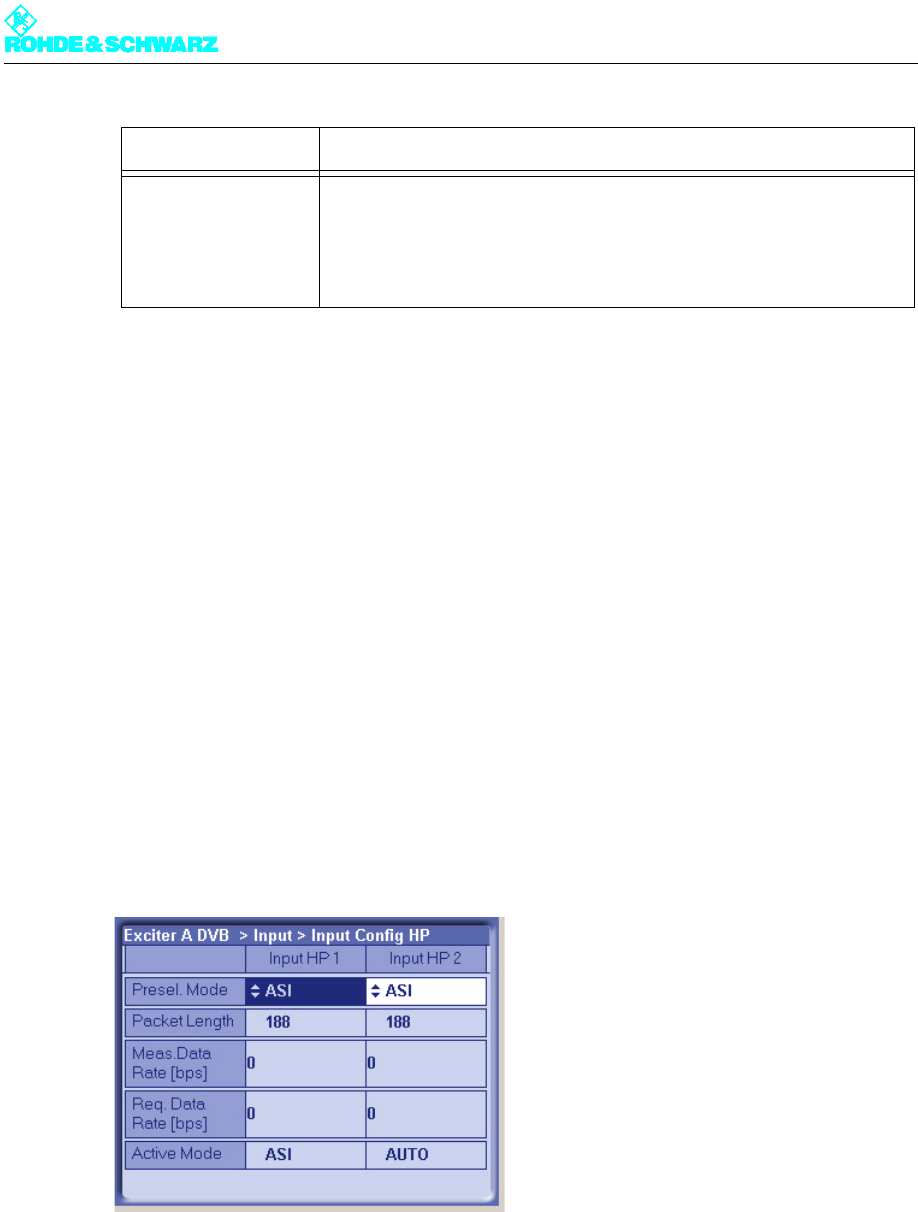
3.5.1 Input > Input Config HP
Amplifier Control Activates and deactivates the amplifier control unit
In R&S low-power transmitters without NETCCU the exciter can have
control of the amplifier. This function is implemented with effect from
software release V1.2.0.
Setting item Description

Chapter 5 Operating
2098.0594.72 - 5.39 - E-1
3.5.1.1 Checking the Measured Data Rate
By comparing the Meas. Data Rate [bps] and Req. Data Rate [bps] displays, it is possible
to check that the input buffers (FIFO) are neither underflowing nor overflowing, since this
would lead to breaks in transmission.
Maximum data processing rate in MFN mode
In MFN mode all null packets are first of all removed from the transport stream. The asso-
ciated useful data rate is then measured and displayed at Meas. Data Rate [bps]. Provided
this measured value stays below the Req. Data Rate [bps] value, trouble-free operation is
possible.
Note When the useful data rate has been measured, stuffing takes place up to the data rate re-
quired, that is, the difference between Req. Data Rate [bps] and Meas. Data Rate [bps]
is made up by inserting null packets.
Setting item Description
Presel. Mode
[Input HP1/Input HP2]
Setting the data format for the data streams HP 1 or HP 2 (operating
and standby signals) on inputs TS 1 IN or TS 3 IN.
The options are as follows:
– AUTO: The data format is recognized automatically
– ASI: Manual setting for an ASI transport stream
– SMPTE: Manual setting for a SMPTE transport stream
In the case of hierarchical coding the operating or standby signal for the
high priority (HP) stream is fed via the two inputs HP 1 and/or HP 2.
Display Description
Packet Length
[Input HP1/Input HP2]
Display showing the packet length detected at the respective input
Meas.Data Rate [bps]
[Input HP1/Input HP2]
Display showing the measured data rate at the respective input. In MFN
mode the net data rate is displayed (without null packets).
Req. Data Rate [bps]
[Input HP1/Input HP2]
Display for checking the measured data rate. Depending on the chosen
network mode, the following information is displayed:
–MFN: Maximum data processing rate
–SFN: Required data rate
Active Mode Display showing the data format detected or set at the respective input:
– ASI: As described
– SMTPE: As described
– Auto: Auto is selected and there is no data stream
Chapter 5 Operating
2098.0594.72 - 5.40 - E-1
Required data rate in SFN mode
In SFN mode the incoming transport stream is passed to processing unchanged. The as-
sociated data rate is then measured and displayed at Meas. Data Rate [bps]. Provided this
measured value matches the Req. Data Rate [bps] to within ± 1 bps, trouble-free operation
is possible.
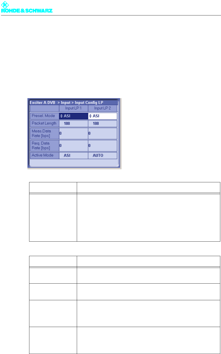
3.5.2 Input > Input Config LP
Setting item Description
Presel. Mode
[Input LP1/Input LP2]
In the case of hierarchical coding: Setting the data format for the low pri-
ority data streams LP 1 or LP 2 (operating and standby signals) on
inputs TS 2 IN or TS 4 IN.
The options are as follows:
– AUTO: The data format is recognized automatically
– ASI: Manual setting for an ASI transport stream
– SMPTE: Manual setting for a SMPTE transport stream
Display Description
Packet Length
[Input LP1/Input LP2]
Display showing the packet length detected at the respective input
Meas.Data Rate [bps]
[Input LP1/Input LP2]
Display showing the measured data rate at the respective input. In MFN
mode the net data rate is displayed (without null packets).
Req. Data Rate [bps]
[Input LP1/Input LP2]
Display for checking the measured data rate. Depending on the chosen
network mode, the following information is displayed:
–MFN: Maximum data processing rate
–SFN: Required data rate
Active Mode Display showing the data format detected or set at the respective input:
– ASI: As described
– SMTPE: As described
– Auto: Auto is selected and there is no data stream
Chapter 5 Operating
2098.0594.72 - 5.41 - E-1
3.5.2.1 Checking the Measured Data Rate
The procedures are the same as for the high priority stream.
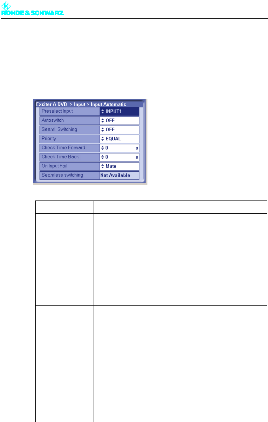
3.5.3 Input > Input Automatic
Setting item Description
Preselect Input For preselecting the inputs
– INPUT 1: The operating input is TS 1 IN. In the case of hierarchical
coding, TS 2 IN is used as a second operating input for the low prior-
ity stream.
– INPUT 2: The operating input is TS 3 IN. In the case of hierarchical
coding, TS 4 IN is used as a second operating input for the low prior-
ity stream.
Autoswitch Switches the automatic input switchover on or off.
In the event of a failure on the active operating input, automatic switcho-
ver to the standby input takes place. The automatic switchover mode is
defined by the following parameter settings.
Seaml. Switching Switches seamless input switchover on or off.
– ON: In the event of a failure, input switchover takes place without a
break in transmission, provided the data streams are synchronized at
the operating and standby inputs.
– OFF: For the purpose of testing the automatic input switchover, the
Seaml. Switching function can be deactivated.
The function has no effect when automatic input switchover is deacti-
vated.
Priority Selection of the priority mode.
– EQUAL: The preselected operating input and standby input have the
same priority. Once a switchover has taken place there is normally no
return switchover to the operating input which previously failed.
– PRIOR: The preselected operating input is the priority input. Once a
switchover has taken place the system switches back to the prese-
lected operating input as soon as the signal reappears.

Chapter 5 Operating
2098.0594.72 - 5.42 - E-1
3.5.3.1 Automatic Input Switchover
The exciter comprises a circuit for automatic switchover from one input to the other, provid-
ed that a valid signal is present at the second input. Before a failure occurs, the preselected
input is active.
The mode of this automatic switchover circuit is defined by the following factors:
– Automatic: ON or OFF (Autoswitch)
– Delay times until switchover (Check Time Forward or Check Time Back)
– Priority mode: Inputs have equal priority or the preselected input has priority (Priority)
– Operating and standby inputs synchronized or not synchronized (in conjunction with
Seamless Switching)
Automatic input switchover ON/OFF
If automatic switchover is OFF, the preselected input remains active even if the input signal
fails.
If automatic switchover is ON and there is a failure at the preselected input, switchover to
the associated standby input takes place.
Priority mode PRIOR (input priority)
Following a switchover of the preselected input, the automatic system switches back to this
priority input as soon as a signal reappears. Switchover is delayed for the set delay times.
Check Time Forward For setting a delay time (0 to 60 s) which must elapse before the
switchover to the standby input takes place in the event of a failure on
the operating input.
Check Time Back For setting a delay time (0 to 60 s) which must elapse before switching
back to the operating input after switching over from the standby input
(which is no longer active).
The function has no effect if the priority mode is set to EQUAL.
On Input Fail For setting the behavior in the event of a defective input signal (synchro-
nization error)
– No Mute: The output signal is not suppressed
– Mute: The output signal is suppressed if the data rate is incorrect or
the MIP is faulty (recommended for SFN)
Display Description
Seamless Switching Status display for indicating whether the input streams are synchronized
on the operating and standby inputs (precondition for seamless input
switchover).
Setting item Description

Chapter 5 Operating
2098.0594.72 - 5.43 - E-1
If the signal fails at both the operating input and the standby input, the priority input remains
active.
Priority mode EQUAL (equal input priority)
Following a switchover of the preselected input, the standby input with the same priority re-
mains active until the input signal fails on this input also. The automatic system switches
back to the preselected input, but only if a signal is present on it once again. Switchover is
delayed for the set delay times.
Note Selecting this operating mode keeps to a minimum the number of switchover operations
and in certain cases the number of breaks in transmission (in the case of unsynchronized
input streams).
3.5.3.2 Behavior in the Event of a Defective Input Signal
SFN mode
In the event of a defective input signal (due for example to an incorrect data rate, defective
or missing MIP, missing or unsynchronized signal) the output signal is in effect suppressed.
In this case the switch setting On Input Fail is meaningless.
MFN mode
The behavior in the event of a defective input signal can be influenced by the On Input Fail
switch as follows:
–Mute: The output signal from the exciter is suppressed as soon as it can no longer be
synchronized with the input signal (from the operating and standby inputs).
–No Mute: The output signal from the exciter is not suppressed, despite a defective input
signal. However, when this happens only null packets are transmitted.
3.6 DVB Parameters Menu
The menu windows in the DVB Parameters menu can be used not only to set (and/or pre-
set) the DVB transmission parameters needed for encoding and modulation, but also to
check the settings used as well as the TPS settings signaled during transmission (TPS =
Transmission Parameter Signaling).
Note Providing there is a MIP (Megaframe Initialization Packet) in the transport stream, TPS in-
formation can also be read out and used for configuring the DVB transmission parameters.
In this case the signaled parameters may not be the same as the manually preset param-
eters.
The menu windows
The DVB Parameters menu leads to the following menu windows:
Chapter 5 Operating
2098.0594.72 - 5.44 - E-1
–TPS: Selection of the TPS source, manual (pre)setting and displaying the active TPS
parameters
–SFN Delay: Displaying and setting signal delay times in the SFN
–Test Signals: Configuring DVB transmission parameters for test mode
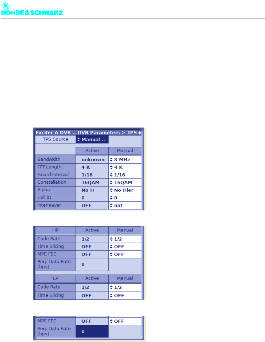
3.6.1 DVB Parameters > TPS
Note The TPS menu window provides comprehensive options for entering settings and obtaining
information. You need to scroll in order to see all the parameter settings.
Selection of the TPS source
The TPS Source switch is used to select the source for the TPS parameters:
–MIP: The TPS information is to be retrieved from the MIP
–Manual Presets: The TPS parameters are to be manually configured

Chapter 5 Operating
2098.0594.72 - 5.45 - E-1
Manual configuration of the TPS parameters
The parameters for DVB-T, DVB-H and hierarchical coding can be configured in the column
on the right, headed Manual. These manual settings are active in the following cases:
– When there is no MIP in the transport stream.
– When there is a MIP in the transport stream, but this is not used because the TPS source
is set to Manual Presets.
Displaying the active TPS parameters
The active (and signaled) TPS parameters are displayed in the column on the left, headed
Active. There are also two displays for the required data rates on one or two active inputs
(see section "Checking the Measured Data Rate").
If the TPS information from the MIP is used, the values displayed in the Active column may
not be the same as the manual settings (Manual column).
The available parameters
Setting item Description
TPS Source Setting the source for the TPS parameters: MIP or manual presets
Display/
Setting item
Description of the
active or manually set TPS parameters
Bandwidth Signal bandwidth
Display/setting: 5, 6, 7 or 8 MHz
FFT Length IFFT length
Display/setting: 2k or 8k; also 4k in the case of DVB-H
Guard Interval Guard interval
Display/setting: 1/4, 1/8, 1/16 or 1/32
Constellation Modulation mode
Display/setting: QPSK, 16QAM or 64QAM
In the case of hierarchical coding the value refers to the sum of the HP
and LP stream constellation points; possible values are therefore:
16QAM or 64QAM
Alpha Hierarchy parameter α
Display/setting:
– No Hier: Non-hierarchical coding
– 1 H: Hierarchical coding with α = 1
– 2 H: Hierarchical coding with α = 2
– 3 H: Hierarchical coding with α = 3
1 H, 2 H or 3 H activates the hierarchical coding mode. However, this is
only possible if Constellation is set to 16QAM or 64QAM.

Chapter 5 Operating
2098.0594.72 - 5.46 - E-1
3.6.1.1 Settings for DVB-T
The following quantities form the standard parameters for DVB-T:
–DVB signal bandwidth: Spectrum bandwidth in the transmit channel
–IFFT length: The signal bandwidth is divided into 2k (2048) or 8k (8192) frequency sub-
carriers. The 4k (4096) option is available for DVB-H only.
–Guard interval: A protection interval of 1/4, 1/8, 1/16 or 1/32 symbol length. The longer
the guard interval, the better the intersymbol echo suppression.
–Code rate: Error correction bits (1/2, 2/3, 3/4, 5/6 or 7/8) added to the information data
in the FEC (forward error correction) block. For instance, a code rate of 5/6 corresponds
to a ratio of 5:1 between information data and FEC.
–Modulation mode: Depending on the modulation mode, a frequency subcarrier may con-
tain 2-bit (QPSK), 4-bit (16QAM) or 6-bit (64QAM) information.
Cell ID Cell ID
Display/setting: 0x0000 to 0xFFFF
The Cell ID can only be retrieved from the MIP if the Tx Automatic is
activated and the Tx address is correctly set (see section "Setup >
DVB").
For the purpose of signaling in the output signal (TPS), Parameter Cell
ID Enable must also be activated (see section "Setup > DVB").
Interleaver Interleaver
Display/setting:
– nat: Default setting ("native") with normal function for DVB-T
– in depth: 8k interleaving for DVB-H at IFFT lengths of 2k and 4k for
improved transmission reliability (DVB-H parameter)
Code Rate [HP/LP] Internal code rate (separate for HP and LP stream)
Display/setting: 1/2, 2/3, 3/4, 5/6 or 6/7
Time Slicing [HP/LP] Time Slicing Flag (DVB-H parameter)
Display/setting separate for HP and LP stream:
– OFF: Default setting; no signaling via flag
– ON: A flag is set in the broadcast DVB signal. This flag informs the
receiver that at least one service in the DVB-H data stream uses time
slicing.
MPE FEC [HP/LP] MPE FEC Flag (DVB-H parameter)
Display/setting separate for HP and LP stream:
– OFF: Default setting; no signaling via flag
– ON: This flag informs the receiver that at least one service in the
DVB-H data stream uses forward error correction for MPE (multipro-
tocol encapsulation).
Req. Data Rate
[HP/LP]
Display showing the required data rate;
cf. section "Input > Input Config HP"
Display/
Setting item
Description of the
active or manually set TPS parameters

Chapter 5 Operating
2098.0594.72 - 5.47 - E-1
3.6.1.2 Settings for DVB-H
Activating DVB-H
)Go to the Setup > DVB menu window and use the Digital Standard switch to select
DVB-H mode.
The setting options for the additional DVB-H functions are enabled.
Additional DVB-H functions
The standard DVB-H (transmission of DVB signals to handheld devices) has all the prop-
erties of DVB-T together with the following additional functions:
– a third IFFT length: 4k
– built-in enhanced error protection: MPE FEC, in-depth interleaving
– time slicing
3.6.1.3 Settings for Hierarchical Coding
Activating hierarchical coding
)Go to the DVB Parameters > TPS menu window for Alpha and select one of the set-
tings 1H, 2H or 3H.
Note The setting Alpha = No Hier disables all LP Stream entries.
Conditions for DVB transmission parameters
With hierarchical coding, the DVB transmission parameters for the LP stream and for the
HP stream must be selected so that they match, in order to satisfy certain conditions. The
user interface is the means of ensuring compliance with these conditions.
The available settings and the conditions they fulfill (Ö via software) are shown in the fol-
lowing table:
HP stream LP stream
DVB bandwidth Manual: 5, 6, 7 or 8 MHz Ö via software: LP = HP
IFFT length Manual: 2 k or 8 k (also 4k in the
case of DVB-H)
Ö via software: LP = HP
Guard interval Manual: 1/4, 1/8, 1/16 or 1/32 Ö via software: LP = HP
Code rate Manual: 1/2, 2/3, 3/4, 5/6 or 7/8 Manual: 1/2, 2/3, 3/4, 5/6 or 7/8
Modulation mode
(constellation)
manual for HP + LP:
16QAM or 64QAM
Ö via software: QPSK or 16QAM
Hierarchy Manual: α = 1, 2 or 4 Ö LP = HP

Chapter 5 Operating
2098.0594.72 - 5.48 - E-1
The hierarchy parameter Alpha
With hierarchical modulation, the entire information of a frequency subcarrier is interpreted
as a 2-bit modulation and an additional 2-bit or 4-bit modulation. Since the 2-bit modulation
merely contains the information on the relevant quadrant in the constellation diagram, it is
very "robust" and is used for the high-priority stream. The second modulation represents
the position specification within the quadrant. With 2-bit or 4-bit (= 4 or 16 constellation
points), it contains more precise information but is also proportionately more "sensitive" to
faults. It is therefore used for the low-priority stream.
In principle: The more constellation points there are and the closer together they are, the
more sensitive the modulation. This basic rule can be used to further increase the robust-
ness of the HP modulation at the expense of the LP modulation. The hierarchy parameter
α is used for this purpose. It is defined as the quotient of two different distances between
adjacent constellation points. The denominator is the distance between points from different
quadrants, the numerator the distance between points from one and the same quadrant. A
high α value therefore always signifies a more robust modulation on the HP channel at the
expense of a more sensitive modulation on the LP channel.
3.6.2 DVB Parameters > SFN Delay
All transmitters in a single-frequency network (SFN) must transmit the same information at
the same time and at the same frequency (single-frequency condition). A number of delay
times occur prior to transmission at the antenna, defining the individual time of transmission
at the transmitter station.
The SFN Delay menu window can be used to check the individual delay times. This makes
it possible to check whether the single-frequency condition is met.
Display Description
Maximum Delay Period of time between the signal leaving the play-out center (MIP
inserter) and its regular transmission at the transmitting antenna. This
delay is set in the MIP inserter and serves as a basis for all the transmit-
ters in the SFN.
Network Delay Signal propagation time between the play-out center (MIP inserter) and
the exciter input. This delay depends on the transmission path used.

Chapter 5 Operating
2098.0594.72 - 5.49 - E-1
Processing Delay Minimum signal transit time through the exciter. This delay depends on
the DVB transmission parameters.
Dynamic Delay Period of time by which signal processing is artificially delayed so that
the desired time of transmission is obtained.
Total Delay Actual signal transit time through the exciter. This is derived from the
sum of the processing delay and the dynamic delay.
Tx Offset Delay The offset in time of transmission (positive or negative) sent to the MIP
for the individual transmitter site, relative to the regular time of transmis-
sion specified by the maximum delay.
For the purpose of display and activation, the Tx Automatic must be
enabled and the Tx address of the transmitter must agree (see section
"Setup > DVB").
If Tx offset delay and static delay are both present at the same time,
their effects combine.
Setting item Description
Static Delay The offset in time of transmission (positive or negative) set manually for
the individual transmitter site, relative to the regular time of transmission
specified by the maximum delay. The static delay can be used to com-
pensate for manufacturing differences between transmitter systems.
If static delay and Tx offset delay are both present at the same time,
their effect combines.
Max Leap in Time In relation to the computed time of transmission, this is the maximum
leap in time that can be corrected without a break in transmission.
Default setting: 10 µs
Display Description
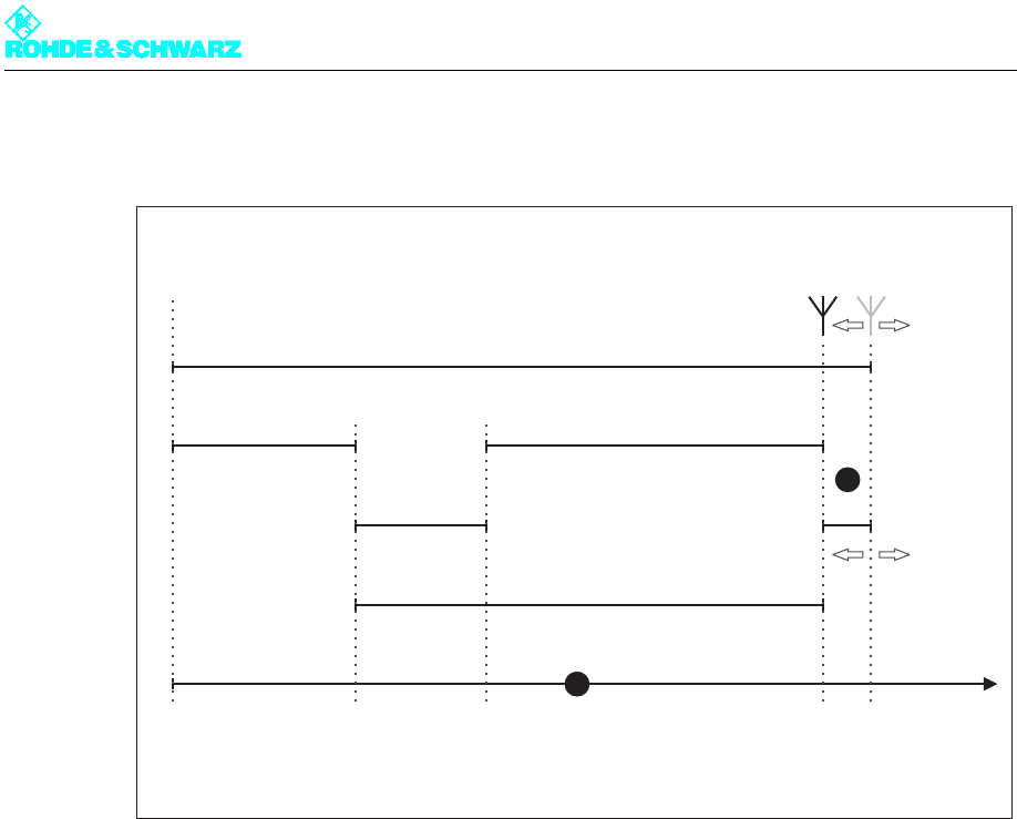
Chapter 5 Operating
2098.0594.72 - 5.50 - E-1
3.6.2.1 Distribution of Delays on the Timeline
Fig. 6 Delays in the SFN
1) Timeline showing the defined times for signal insertion (MIP Inserter), signal feed to the exciter (TS x IN), time
of transmission at the station (Tx) and regular time of transmission (SFN)
2)
?
T = the difference between the individual time of transmission at the station and the regular time of transmis-
sion in the SFN; in this example the sign is negative
The microcontroller in the exciter calculates the dynamic delay for the planned time of trans-
mission on the basis of the details in the MIP and the measured signal processing time.
Note In order to comply with the single-frequency condition, the value of the dynamic delay must
be between 0 and 1 second.
3.6.3 DVB Parameters > Test Signals
The Test Signals menu window is used to generate test signals.
MIP Inserter
TSxIN
Tx
SFN
Play-out
Center
timeline
Transmitter
Antenna
Maximum Delay
Network Delay
Processing Delay
Dynamic Delay
Total Delay
∆T = Static Delay
+ Tx Offset Delay
<0 >0
1
2

Chapter 5 Operating
2098.0594.72 - 5.51 - E-1
Setting item Description
PRBS Insertion Insertion of a PRBS sequence instead of the transport stream present at
the input
Selection:
– OFF: Normal operating status, test sequence not active
– 2^23-1, 2^15-1 or 2^9-1: Displayed PRBS sequence selected
Test Signal Insertion Insertion of unmodulated test carriers or suppression of modulated car-
rier ranges in the output frequency spectrum
Selection:
– OFF: Normal operating status, test signal not active
– CARRIER 1: Insertion of an unmodulated test carrier at carrier
position 1
– CARRIER 2: Insertion of an unmodulated test carrier at carrier
position 2
– C1 and C2: Insertion of two unmodulated test carriers at carrier
position 1 and carrier position 2
– BANDPASS: Suppression of the modulated carriers from position 0 to
carrier position 1 and from carrier position 2 to the end of the fre-
quency spectrum
– BANDSTOP: Suppression of the modulated carriers in the range
between carrier position 1 and carrier position 2
In the BANDPASS and BANDSTOP functions, the value for carrier 1
must be smaller than the value for carrier 2.
Carrier 1 Sets the position for test carrier 1
Carrier 2 Sets the position for test carrier 2
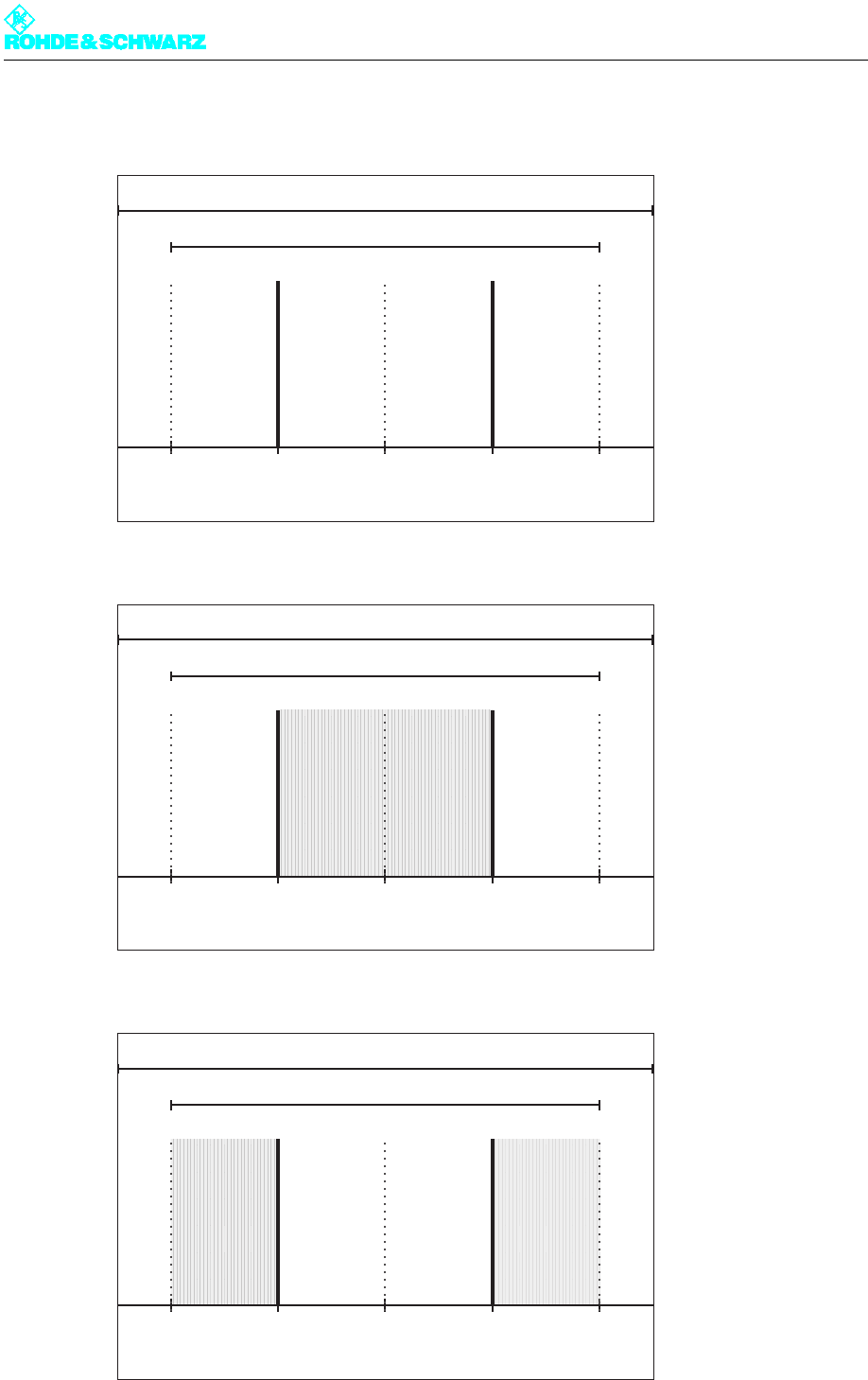
Chapter 5 Operating
2098.0594.72 - 5.52 - E-1
3.6.3.1 The Arrangement of Test Signals in the Output Frequency Spectrum
Fig. 7 Test Signal Insertion function | C1 and C2
Fig. 8 Test Signal Insertion function | Bandpass
Fig. 9 Test Signal Insertion function | Bandstop
used Bandwidth
Channel Bandwidth
C1 C2
2k 0
4k 0
8k 0
852
1704
3408
1704
3408
6816
used Bandwidth
Channel Bandwidth
C1 C2
2k 0
4k 0
8k 0
852
1704
3408
1704
3408
6816
used Bandwidth
Channel Bandwidth
C1 C2
2k 0
4k 0
8k 0
852
1704
3408
1704
3408
6816
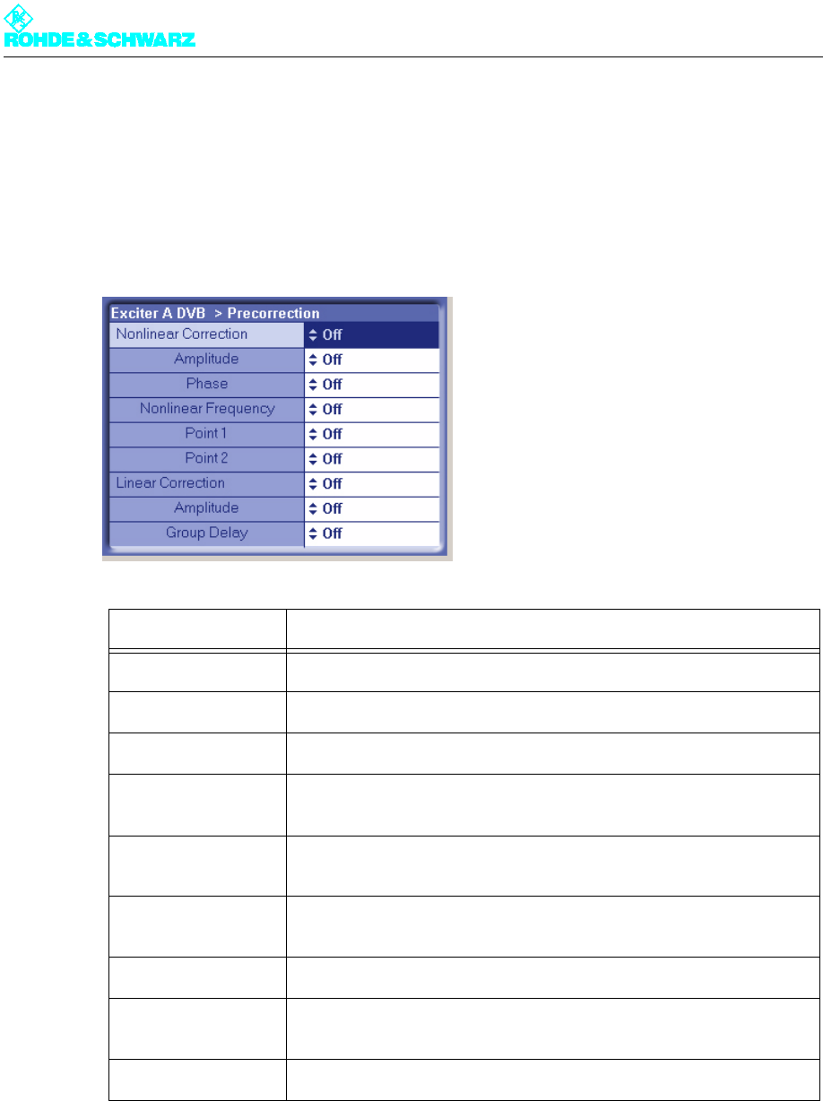
Chapter 5 Operating
2098.0594.72 - 5.53 - E-1
3.7 Precorrection Menu
In the Precorrection menu window, you can activate or deactivate individual precorrector
branches without having to access the precorrector GUI (see the section "Introduction to
Operation of the Precorrector"). The different switch settings (On/Off) correspond to the re-
lated settings in the precorrector GUI.
3.8 RF Menu
The menu windows in the RF menu are used to make the settings for frequency generation,
modulation and RF monitoring.
Setting item Description
Nonlinear Correction Switches the entire nonlinear correction on or off.
– Amplitude Switches the amplitude correction in the nonlinear corrector on or off.
– Phase Switches the phase correction in the nonlinear corrector on or off.
– Nonlinear Fre-
quency
Switches the entire nonlinear frequency response correction on or off.
– Point 1 Switches the frequency response influence on branch 1 on or off (non-
linear frequency response correction).
– Point 2 Switches the frequency response influence on branch 2 on or off (non-
linear frequency response correction).
Linear Correction Switches the entire linear correction on or off.
– Amplitude Switches the amplitude frequency response correction in the linear cor-
rector on or off.
– Group Delay Switches the group delay correction in the linear corrector on or off.
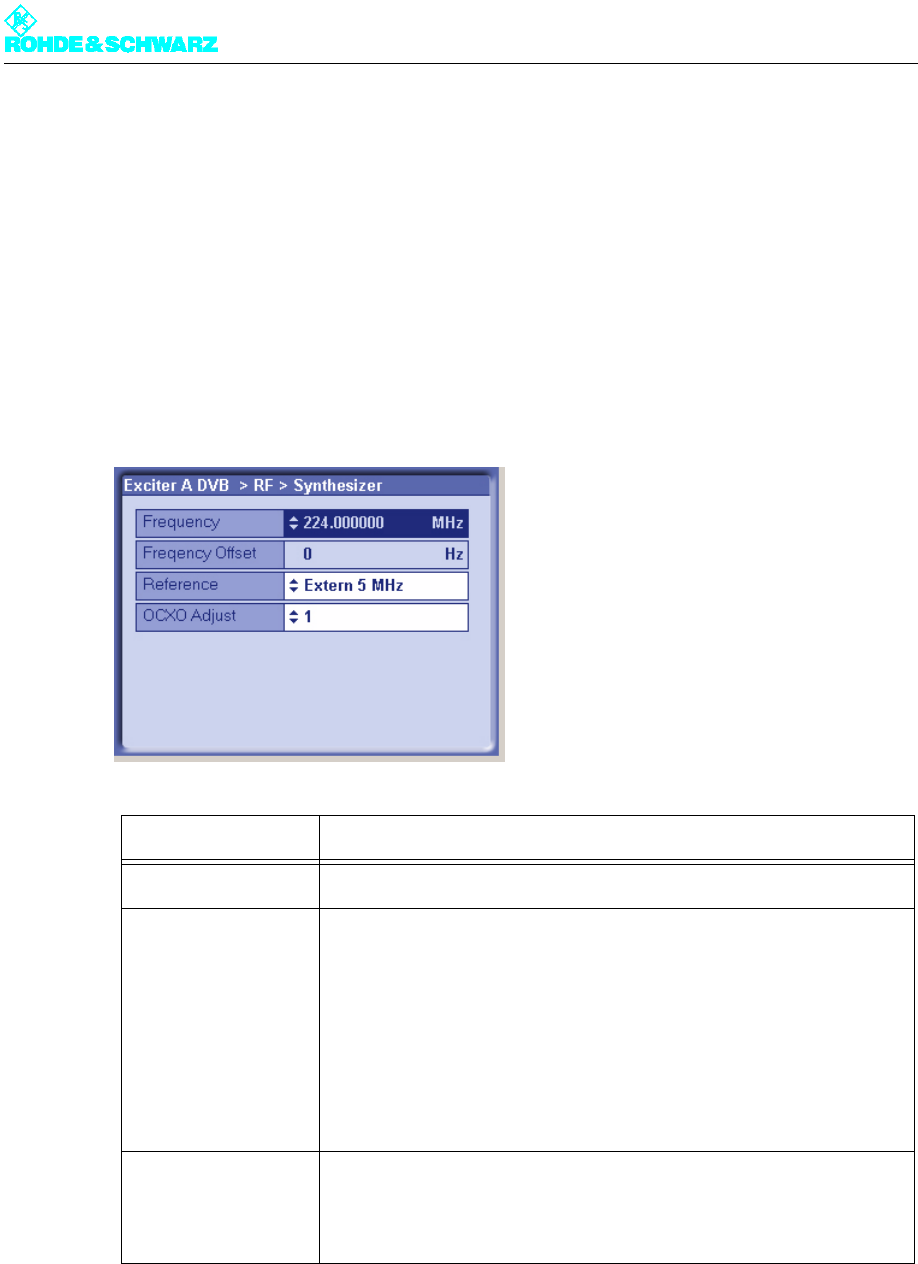
Chapter 5 Operating
2098.0594.72 - 5.54 - E-1
The menu windows
The RF menu leads to the following menu windows:
–Synthesizer: Set the channel center frequency and the reference frequency source
–Output: Enable the RF output, activate output level control or set the level manually, cor-
rect the amplitude frequency response of subsequent components
–IQ Adjust: Adjust the modulator
3.8.1 RF > Synthesizer
Setting item Description
Frequency Setting the channel center frequency
Reference Selecting the reference source for stabilization of the frequency pro-
cessing (reference frequency source). The following settings are possi-
ble:
– Internal: Operation without an external reference frequency source.
– External 5 MHz: Operation with an external 5 MHz reference.
– External 10 MHz: Operation with an external 10 MHz reference.
– External 1pps: Operation with an external time reference (1 pps)
The same setting options can be found in the RF > Reference menu
window.
OCXO adjust Setting for adjusting the internal OCXO frequency (for "Internal" mode).
The same setting options can be found in the RF > Reference menu
window.

Chapter 5 Operating
2098.0594.72 - 5.55 - E-1
3.8.1.1 Reference Frequency Source
The basis for frequency generation in the exciter is a 10 MHz oven controlled crystal oscil-
lator (OCXO). This OCXO can be operated in two different modes:
"Internal" mode
The OCXO runs in uncontrolled mode.
It obtains its control voltage via a D/A converter which can be set using the OCXO adjust
item. The frequency of the OCXO present at the 10 MHz MONITORING test output (on the
front panel of the exciter) can be adjusted to 10 MHz if necessary.
"External" mode
The OCXO runs in controlled mode.
Due to the control, the control voltage generated by the D/A converter is adapted on an on-
going basis so that the 10 MHz frequency of the OCXO is synchronized to the externally
supplied 5 MHz or 10 MHz reference frequency, or to the external 1-pps signal.
3.8.1.2 Holdover Mode (In Case of Failure of the Reference Frequency)
As soon as a failure of the external reference frequency is detected, the control voltage for
the OCXO is no longer modified. The result of this is that the RF generation is now based
on the stability of the OCXO.
As soon as the external reference frequency is restored, the control voltage on the OCXO
will be controlled again with the externally supplied reference frequency.
Display Description
Frequency offset Any frequency offset is added straight to the channel center frequency.
The frequency offset transferred in the MIP is addressed to a particular
transmitter in the network and is evaluated only if the Tx address set in
the Setup > DVB menu window is the correct recipient. For the purpose
of display and activation the Tx Automatic also needs to be enabled
(see section "Setup > DVB").
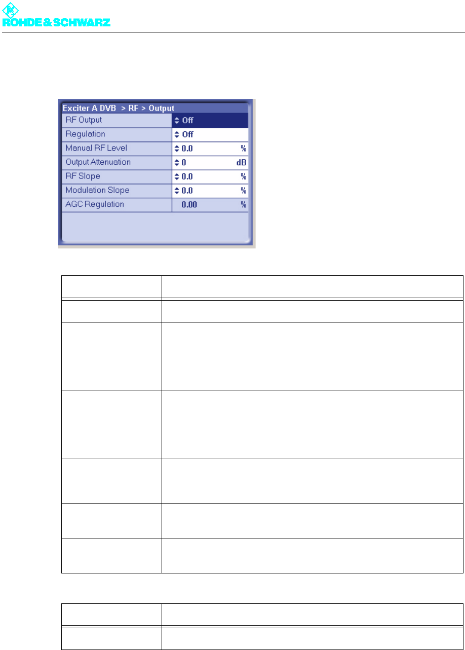
Chapter 5 Operating
2098.0594.72 - 5.56 - E-1
3.8.2 RF > Output
3.8.2.1 Output Level Control
The output power delivered by the exciter is determined by a nominal output level controller.
Setting item Description
RF Output Enables (On) or disables (Off) the RF output.
Regulation Activates (On) or activates (Off) the output level control. During trans-
mission operation, control must be enabled.
The current status of the related level adjuster is displayed as a percent-
age under RF > RF Monitor > AGC Exciter.
Manual RF Level Manual setting of the output level; the setting has an effect only if output
level control is deactivated.
The current status of the related level adjuster is displayed as a percent-
age under RF > RF Monitor > AGC Exciter.
Output Attenuation For level adaptation purposes, an integrated attenuator with a value of
3 dB, 6 dB or 9 dB can be connected. This has no influence on the level
control.
RF Slope Correction of a slope of the amplitude frequency response in the spec-
trum for equalizing subsequent components (output stage, filter).
Modulation Slope Correction of a curvature of the amplitude frequency response in the
spectrum for equalizing subsequent components (output stage, filter).
Display Description
AGC Regulation Displays the level of the output level control

Chapter 5 Operating
2098.0594.72 - 5.57 - E-1
For test purposes this controller can be deactivated. The output level is then set via the
Manual RF Level control element.
Note If Manual RF Level is set too low, the RF FAIL error will be generated.
3.8.3 RF > IQ Adjust
When it is delivered from the factory, the I/Q modulator is preadjusted so that no customer
intervention is normally required.
If you need a new I/Q adjustment at a later point in time, this will involve the use of the ac-
tuators in the RF > IQ Adjust menu window.
The I/Q adjustment is dependent on the automatically selected intermediate frequency
LO1. Accordingly, it applies only for the intermediate frequency displayed under LO1 Fre-
quency.
Note The following table shows the relationship between the set vision carrier frequency and in-
termediate frequency LO1:
Note For information on how to carry out a manual I/Q adjustment, see the section "Manual Ad-
justment of the I/Q Modulator".
Vision carrier frequency Intermediate frequency
47 MHz ≤ fV < 510 MHz ⇒LO1 = 2160 MHz
510 MHz ≤ fV < 580 MHz ⇒LO1 = 1920 MHz
580 MHz ≤ fV < 680 MHz ⇒LO1 = 2160 MHz
680 MHz ≤ fV < 860 MHz ⇒LO1 = 1920 MHz
Setting item Description
Auto I/Q Adjust An option for automatic I/Q adjustment will be implemented in a later
software release.
I/Q Test Signal Switches a test signal on or off for use in performing manual I/Q adjust-
ment.
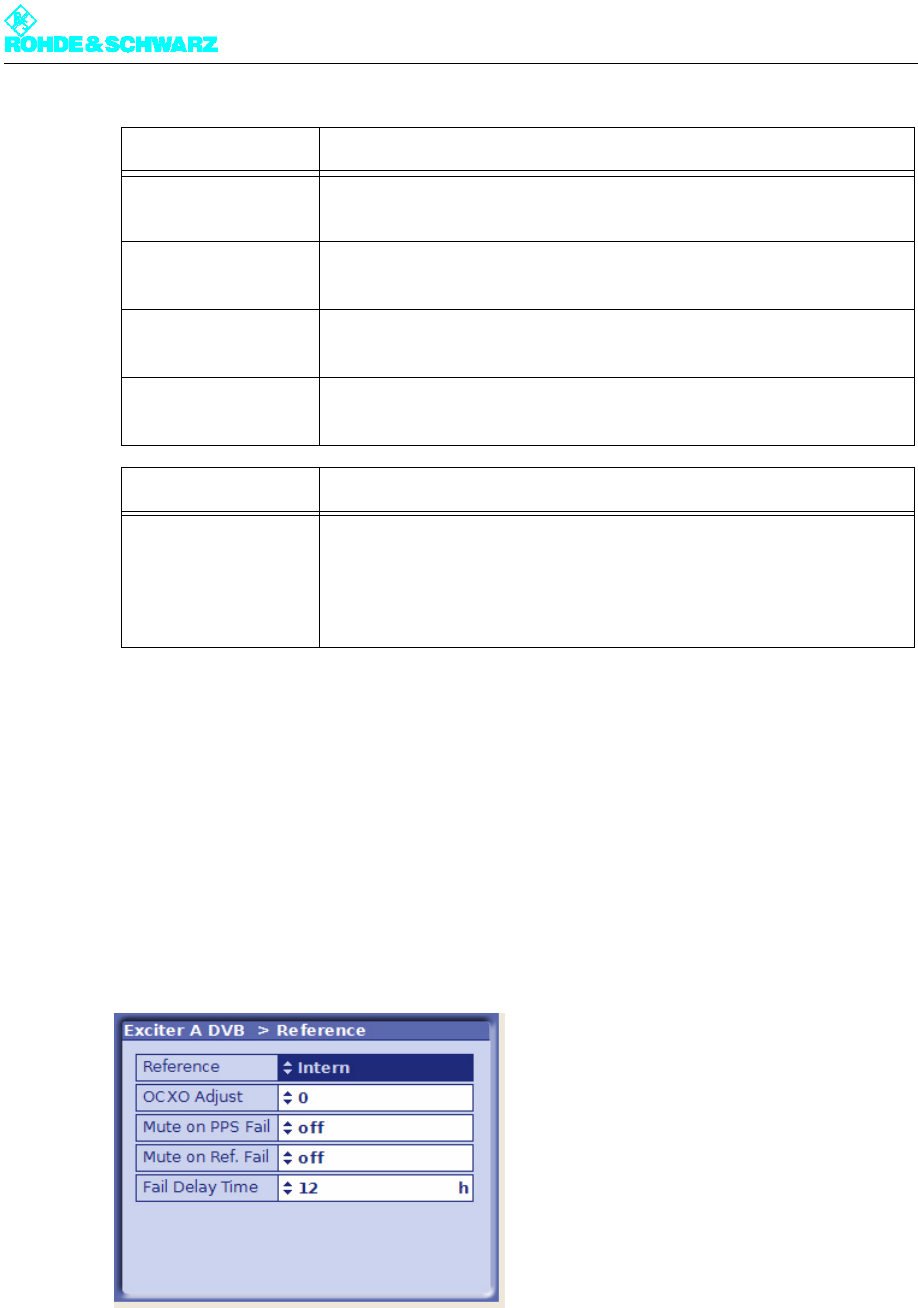
Chapter 5 Operating
2098.0594.72 - 5.58 - E-1
3.9 Reference Menu
A reference source for stabilization of the frequency processing (reference frequency
source) can be selected via the Reference menu window.
It is also possible to set the behavior of the exciter in the event of failure of the reference
sources for frequency processing and for synchronization in the SFN (external 1-pps sig-
nal).
Bias Coarse [I/Q] Course setting of an actuator for suppressing the undesired center car-
rier; setting range: -1023 to +1023
Bias Fine [I/Q] Fine setting of an actuator for suppressing the undesired center carrier;
setting range: -32767 to +32767
Gain (I/Q) Setting of an actuator for suppressing the undesired carrier in the side-
band; setting range: 0 to 255
Phase Setting of an actuator for suppressing the undesired carrier in the side-
band; setting range: -14 to +14
Display Description
LO1 Frequency Display of the intermediate frequency LO1 which is automatically set in
the modulator (1.92 GHz or 2.16 GHz)
The adjustment values for the actuators described above apply only for
the displayed intermediate frequency.
Setting item Description

Chapter 5 Operating
2098.0594.72 - 5.59 - E-1
3.9.1 Behavior in the Event of Failure of a Reference Source
The behavior in the event of failure of the reference frequency source or time reference is
defined by the settings in the Reference menu window.
The failure of a required or set reference source is indicated as follows:
Setting item Description
Reference Selection of the reference frequency source. The following settings are
possible:
– Internal: Operation without an external reference frequency source
– External 5 MHz: Operation with an external 5 MHz reference
– External 10 MHz: Operation with an external 10 MHz reference
– External 1pps: Operation with an external time reference (1 pps)
The same setting option can be found in the RF > Synthesizer menu
window.
OCXO Adjust Setting for adjusting the internal OCXO frequency (for "Internal" mode)
The same setting option can be found in the RF > Synthesizer menu
window.
Mute on PPS Fail For setting the behavior in SFN mode in the event of failure of the exter-
nal time reference. The following settings are possible:
– off: The output signal is not suppressed.
– only at startup: The output signal is suppressed at startup until a valid
1-pps signal is detected; if the 1-pps signal fails after synchronization,
the output signal is no longer suppressed
– after fail delay time: The output signal is suppressed if the 1-pps sig-
nal fails for longer than the period specified at Fail Delay Time
This is the recommended setting for operation in SFN mode.
Mute on Ref. Fail For setting the behavior in SFN and MFN mode in the event of failure of
the external reference frequency source. The following settings are pos-
sible:
– off: The output signal is not suppressed.
– only at startup: The output signal is suppressed at startup until a valid
reference source is detected; if the reference source fails after syn-
chronization, the output signal is no longer suppressed
– after fail delay time: The output signal is suppressed if the reference
source fails for longer than the period specified at Fail Delay Time
This is the recommended setting for operation in SFN mode.
Fail Delay Time Delay time until the output signal is suppressed after failure of a refer-
ence source. The setting takes effect if the 'after fail delay time' behavior
is set at Mute on PPS Fail or Mute on Ref. Fail.
Selection: 0 to 24 hours

Chapter 5 Operating
2098.0594.72 - 5.60 - E-1
3.10 Device Info Menu
The menu windows under Device Info contain the electronic type plates for the exciter as a
whole as well as for the individual modules or elements in the exciter:
– Exciter (complete device)
– Boards (modules)
– Mainboard
– Input interface
– RF board
– Synth 1
– Synth 2
The structure of the different type plates is more or less identical. The information which is
displayed is explained below using the exciter type plate as an example:
LED (front panel) LED (Status menu) Logbook entry
In SFN mode in
the event of failure
of
Reference fre-
quency source:
5 MHz, 10 MHz or
1pps
REF FAIL: Yellow – Reference: - OFF -
– Sum Warning: Yellow
no reference
Time reference:
1pps
REF FAIL: Yellow – 1 PPS: - OFF -
– Sum Warning: Yellow
Ext PPS Fail
In MFN mode in
the event of failure
of
Reference fre-
quency source:
5MHz or 10MHz
REF FAIL: Yellow – Reference: - OFF -
– Sum Warning: Yellow
no reference
Reference fre-
quency source:
1pps
REF FAIL: Yellow – 1 PPS: - OFF -
– Sum Warning: Yellow
Ext PPS Fail
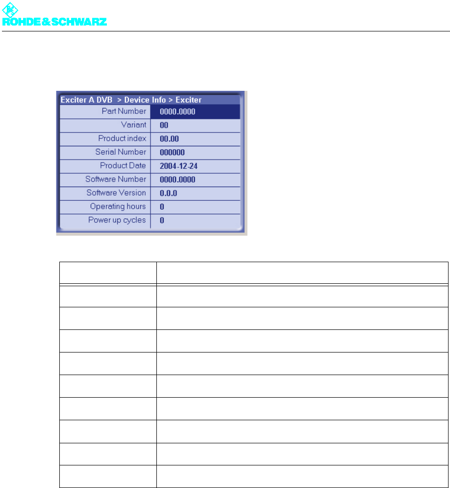
Chapter 5 Operating
2098.0594.72 - 5.61 - E-1
Device Info > Exciter
The information saved here is used for troubleshooting purposes. In case servicing is re-
quired, this information allows you to precisely identify the defective component and order
a replacement.
Display Description
Part Number Part number
Variant Device or module variant (model)
Product Index Product modification index
Serial Number Serial number
Product Date Date of production
Software Number Part number for the software
Software Version Version number for the software
Operating hours Number of operating hours
Power up cycles Number of times device has been switched on/off
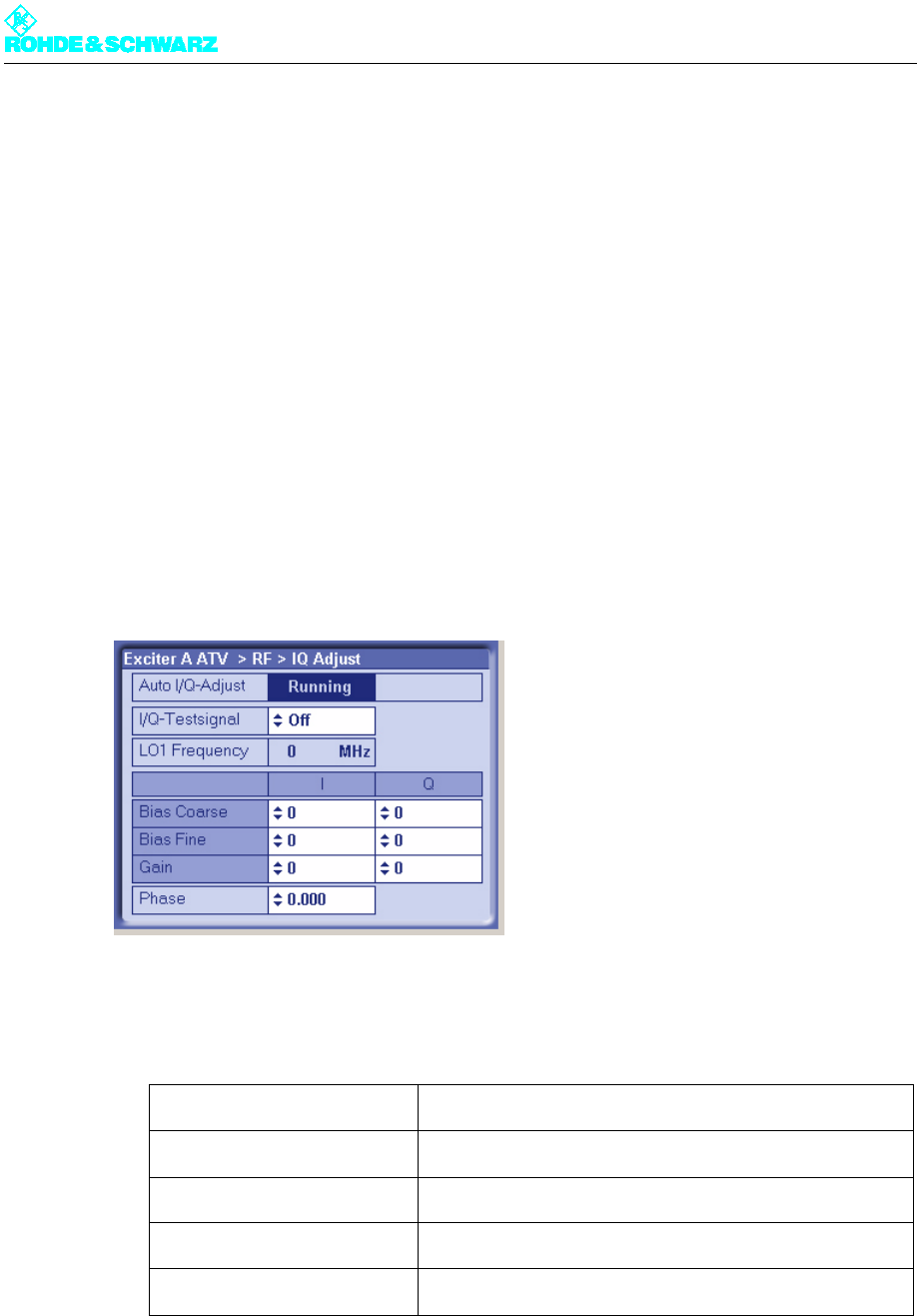
Chapter 5 Operating
2098.0594.72 - 5.62 - E-1
4 Manual Adjustment of the I/Q Modulator
Note Before performing the adjustment, make sure that the exciter has been in operation for at
least 15 minutes.
Objective
If quadrature modulation were optimal (theoretically possible), the residual carrier would be
completely suppressed. In actual practice however, residual carriers arise (e.g. due to
crosstalk). They must be suppressed using suitable correction carriers.
The objective of I/Q adjustment is to suppress the undesired center carrier and undesired
carrier in the sideband with respect to a test carrier by better than 70 dB.
Preparation and test carrier measurement
1. Call up the exciter menu with RF > IQ Adjust.
2. Use the I/Q Test Signal switch to turn on the test signal.
3. Connect a spectrum analyzer to the RF MONITORING output on the front panel of the
exciter and make the following settings:
Center Frequency Frequency of the vision carrier
Span 6 MHz
Resolution BW 30 kHz
Video BW 300 Hz
Sweep Coupled

Chapter 5 Operating
2098.0594.72 - 5.63 - E-1
Fig. 10 Spectrum analyzer display prior to adjustment
1) Undesired carrier in the sideband at the vision carrier frequency + 2.5 MHz
2) Undesired center carrier at the vision carrier frequency
3) Desired test carrier at the vision carrier frequency - 2.5 MHz
Implementation
1. Set the Bias Fine [I/Q] actuators to zero.
2. Course adjustment, center carrier: Using the Bias Coarse [I/Q] actuators, suppress the
undesired center carrier as much as possible with respect to the test carrier. You should
individually adjust each actuator going back and forth several times until you achieve an
optimum value.
3. Sideband adjustment: Use the Gain [I/Q] and Phase actuators to suppress the undes-
ired carrier in the sideband by more than 70 dB with respect to the test carrier. You
should individually adjust each actuator going back and forth several times until you
achieve an optimum value.
4. Course adjustment, center carrier optimization: Using the Bias Coarse [I/Q] actuators,
suppress the undesired center carrier as much as possible with respect to the test car-
rier. You should individually adjust each actuator going back and forth several times until
you achieve an optimum value.
5. Fine adjustment, center carrier: If the center carrier is suppressed by less than 70 dB,
carry out a fine adjustment using the Bias Fine [I/Q] actuators.
1AP
CLRWR
A
Ref 20 dBm Att 45 dB
EXT
EXREF
Center 602 MHz Span 10 MHz1 MHz/
*RBW 30 kHz
*VBW 300 Hz
SWT 1.9 s
-80
-70
-60
-50
-40
-30
-20
-10
0
10
20
1
3
2
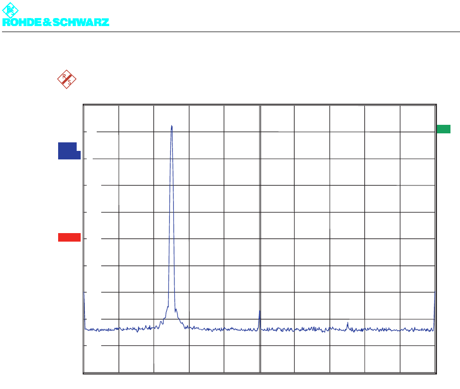
Chapter 5 Operating
2098.0594.72 - 5.64 - E-1
Fig. 11 Spectrum analyzer display after the adjustment
6. Use the I/Q Test Signal switch to turn the test signal back off.
1AP
CLRWR
A
Ref 20 dBm Att 45 dB
EXT
EXREF
Center 602 MHz Span 10 MHz1 MHz/
*RBW 30 kHz
*VBW 300 Hz
SWT 1.9 s
-80
-70
-60
-50
-40
-30
-20
-10
0
10
20
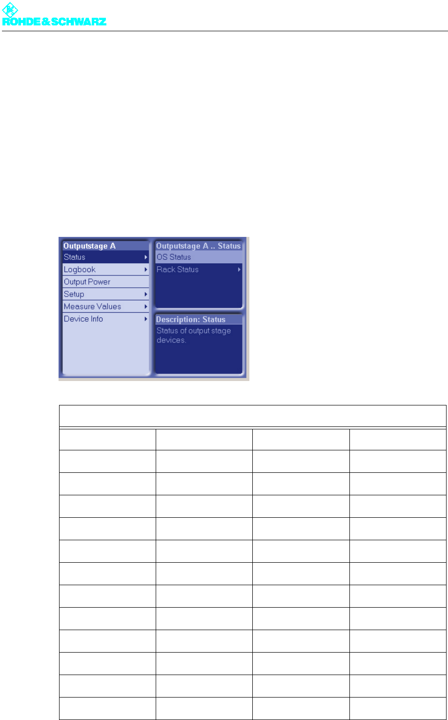
Chapter 5 Operating
2098.0594.72 - 5.65 - E-1
5 Outputstage A/B Menus
You can use the Outputstage A/B menus to operate and configure the transmitter rack and
the amplifier and to call up information.
Note The Outputstage B menus and menu windows are identical to the Outputstage A menus
and menu windows.
5.1 Overview of Menus
Outputstage A menu structure
Level 1 Level 2 Level 3 Level 4
Status
OS Status
Rack Status
Rack 1
Rack controller
Logbook
Summary
Status
Warning
Fault
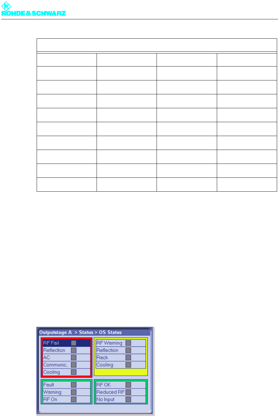
Chapter 5 Operating
2098.0594.72 - 5.66 - E-1
5.2 Status Menu
The Status menu provides an overview of faults, warnings and status messages relating to
the individual output stage components.
5.2.1 OS Status Menu Window
Outputstage A > Status > OS Status
The OS Status menu window provides an overview of faults, warnings and status messag-
es relating to the output stage components.
The following table explains the meaning of the individual display fields:
Output Power
Setup
OS Setup
Measure Values
Rack Measure Values
Rack 1
Device Info
Rack 1
Outputstage A menu structure

Chapter 5 Operating
2098.0594.72 - 5.67 - E-1
5.2.2 Status/Rack Controller Menu Window
Outputstage A > Status > Rack Status > Rack x > Rack Controller
The Status/Rack Controller menu window provides you with status information about the
rack controller.
Display Description
RF Fail Red: Antenna output power below the fault threshold that has been set
Reflection Red: Antenna reflected power above the fault threshold that has been
set
AC Red: Interference AC supply voltage (e.g. phase absent)
Communic.. Red: Communication to output stage interrupted
Cooling Red: Disruption to cooling system, both fans failed
Fault Red: Output stage sum fault
Warning Yellow: Output stage sum warning
RF On Green: Antenna output power above the fault threshold that has been
set
RF Warning Yellow: Antenna output power below the warning threshold that has
been set
Reflection Yellow: Antenna reflected power above the warning threshold that has
been set
Rack Yellow: Fault on at least one transmitter rack
Cooling Yellow: Fault on cooling system
RF OK Green: Antenna output power above the warning limit that has been set
Reduced RF Yellow: Amplifiers operating on reduced power (VF absent)
No Input Yellow: No input signal to amplifiers

Chapter 5 Operating
2098.0594.72 - 5.68 - E-1
The following table explains the meaning of the individual display fields:
Display Description
Fault Red: Transmitter rack sum fault
Cooling Fa.. Red: Cooling system sum fault
Temp. Fault Red: Outlet temperature above the fault threshold that has been set
Abs. 1 Fault Red: Fault on absorber 1
Abs. 2 Fault Red: Fault on absorber 2
AC Fault Red: Network interference (e.g. phase absent)
DC Fault Red: Fault on auxiliary power supply
Link OK Green: Communication to transmitter rack present
Rack On Green: On command present
Warning Yellow: Transmitter rack sum warning
Ext. Coolin.. Yellow: Disruption to ext. cooling
Fan 1 Fault Yellow: Fault on fan 1
Fan 2 Fault Yellow: Fault on fan 2
Amp. Fault Yellow: Amplifier sum fault (at least one amplifier showing interference)
Red. Ref. E. Yellow: Exciter A initiates reduction in transmitter output power (VF
absent)
Red. Ref. E. Yellow: Exciter B initiates reduction in transmitter output power (VF
absent)
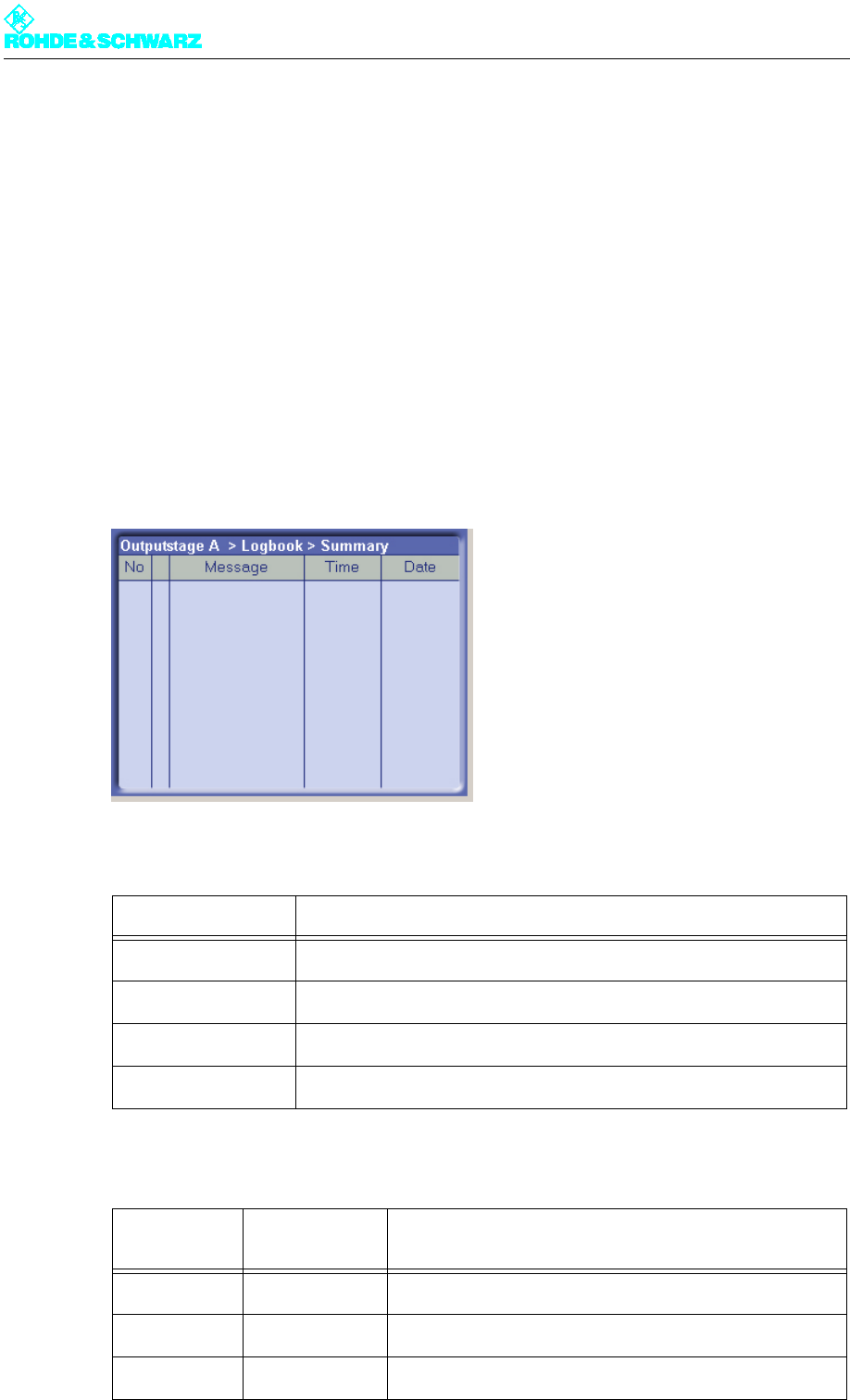
Chapter 5 Operating
2098.0594.72 - 5.69 - E-1
5.3 Logbook Menu
You can use the Logbook menu to query status and error messages about the output
stage.
5.3.1 Logbook Menu Window
Outputstage A > Logbook
You can use the Logbook menu to query status and error messages about the output
stage. The Logbook menu windows provide an overview of status messages, warning mes-
sages and fault messages about the output stage.
Note You can call up Logbook entries via the Summary, Status, Warning and Fault windows.
The following table explains the meaning of the columns:
The arrows in the second column have the following meanings:
Column Description
No Consecutive entry number
Message Message
Time Time the message was received
Date Date the message was received
Arrow direc-
tion Arrow color Description
Up The event has just occurred.
Down The event is no longer current or relevant.
Red Fault
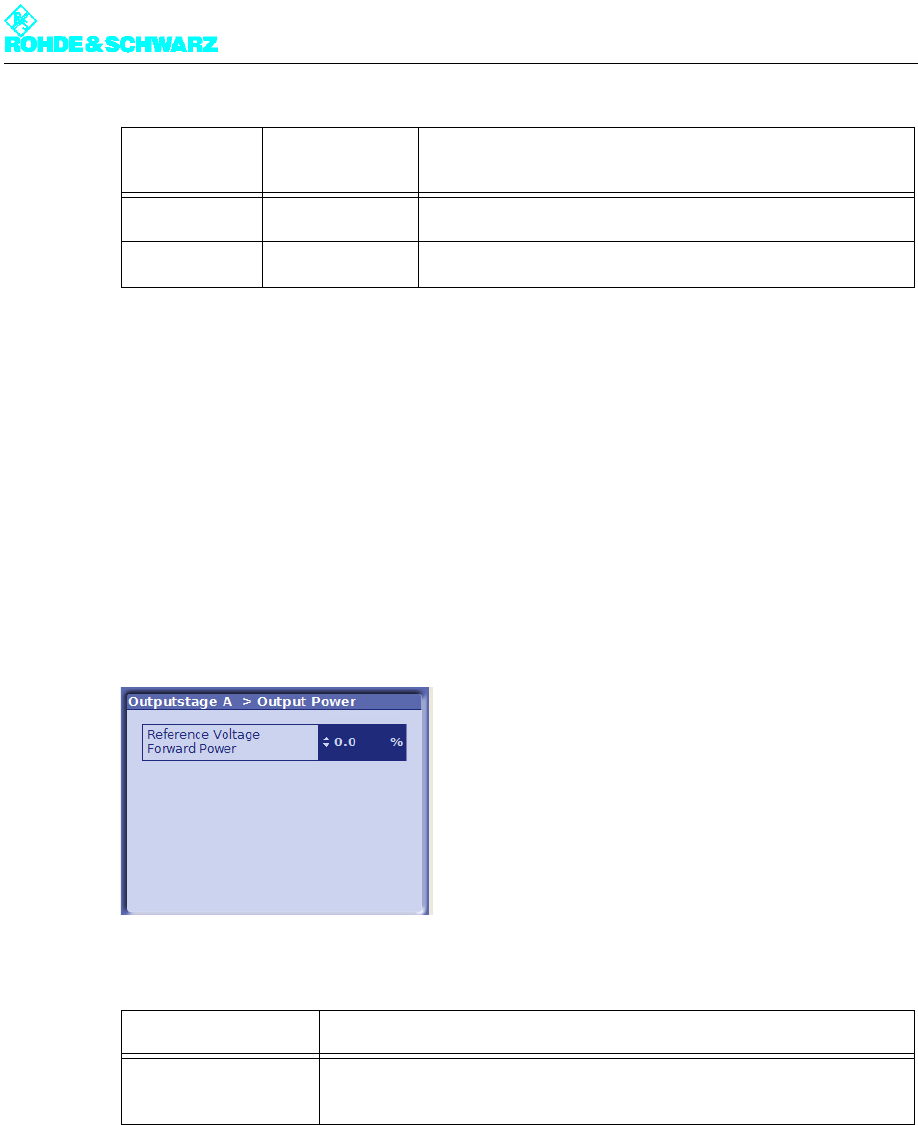
Chapter 5 Operating
2098.0594.72 - 5.70 - E-1
5.4 Output Power Menu
You may use the Output Power menu to access the Output Power window.
5.4.1 Output Power Menu Window
Outputstage A > Output Power
Use the Output Power menu window to set the transmitter output power.
The following table explains the meaning of the individual settings:
5.5 Setup Menu
You may use the Setup menu to access the OS Setup window.
5.5.1 OS Setup Menu Window
Outputstage A > Setup > OS Setup
Yellow Warning
Green Status: In order
Setting Description
Reference Voltage
Forward Power
For setting the forward power.
Values from 0% to 100%
Arrow direc-
tion Arrow color Description
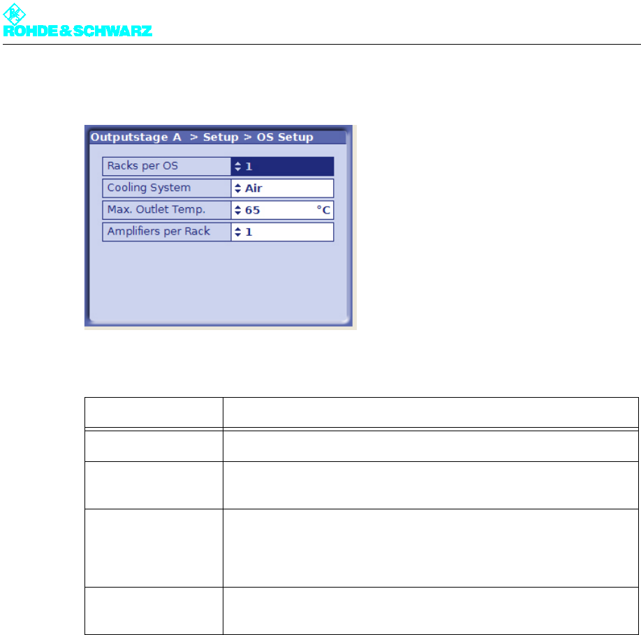
Chapter 5 Operating
2098.0594.72 - 5.71 - E-1
You can enter the basic settings for the output stage in the OS Setup menu window.
The following table explains the meaning of the individual settings:
5.6 Measure Values Menu
You can use the Measure Values menu to read results.
5.6.1 Measure Values/Rack Controller Menu Window
Outputstage A > Measure Values > Rack Measure Values > Rack x > Rack Controller
The Measure Values/Rack Controller menu window displays the inlet and outlet air tem-
peratures and the transmitter rack control voltage.
Setting Description
Racks per OS For entering the number of racks belonging to the transmitter
Cooling System For setting the cooling system used
Value: Air
Max. Outlet Temp. For inputting the maximum permitted outlet air temperature
If the entered limit is exceeded the rack controller switches off the trans-
mitter rack.
Value: 45 °C - 65 °C
Amplifiers per Rack For entering the number of amplifiers installed in the rack
Value: 1 - 4
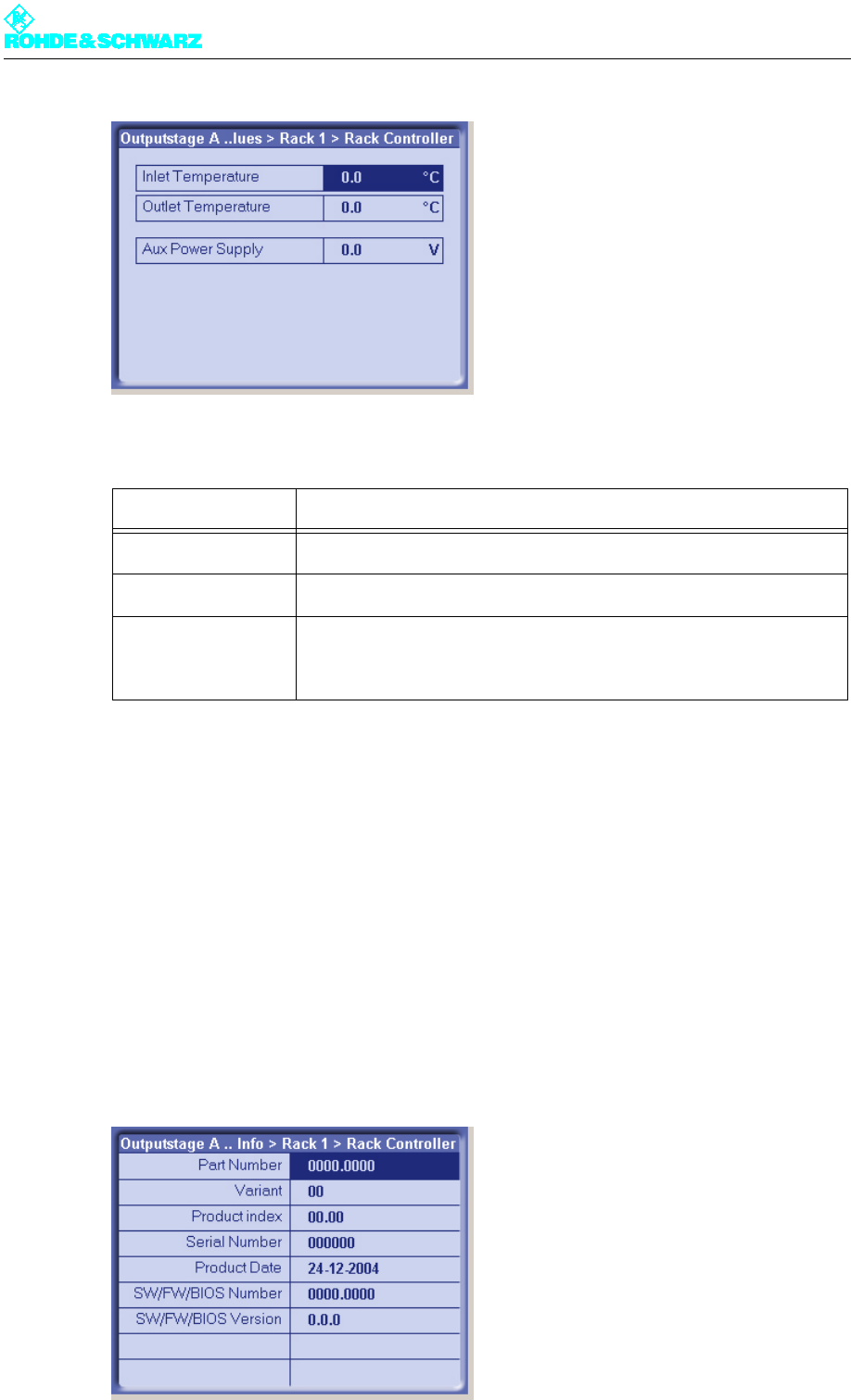
Chapter 5 Operating
2098.0594.72 - 5.72 - E-1
The following table explains the meaning of the fields:
5.7 Device Info Menu
You can use the Device Info menu to call for information on the transmitter rack.
5.7.1 Device Info/Rack Controller Menu Window
Outputstage A > Device Info > Rack x > Rack Controller
You can use the Device Info/Rack Controller menu to call for information on the transmit-
ter rack.
Display Description
Inlet Temperature Inlet temperature of the cooling medium (intake)
Outlet Temperature Outlet temperature of the cooling medium (outgoing air)
Aux Power Supply Control voltage of the internal auxiliary power supply for the transmitter
rack
The value must be between 3.7 V and 4.4 V.

Chapter 5 Operating
2098.0594.72 - 5.73 - E-1
The following table explains the meaning of the display fields:
Display Description
Part Number R&S stock number
Variant Model (basic model = 02)
Product Index Hardware amendment index
Serial Number Serial number
Product Date Date of production
SW/FW/BIOS Number R&S stock number for software, firmware or BIOS
SW/FW/BIOS Version Version number of software, firmware or BIOS