Acrodyne NW8201E DIGITAL TELEVISION BROADCAST TRANSMITTER User Manual 32 NV8202 26 04 06 01 00
Acrodyne Industries, Inc. DIGITAL TELEVISION BROADCAST TRANSMITTER 32 NV8202 26 04 06 01 00
Acrodyne >
Contents
- 1. Users Manual Part 1
- 2. Users Manual Part 2
- 3. Users Manual Part 3
- 4. Users Manual Part 4
- 5. Users Manual Part 5
- 6. Users Manual Part 6
- 7. Users Manual Part 7
- 8. Users Manual Part 8
- 9. Users Manual Part 9
- 10. Users Manual Part 10
- 11. Users Manual Part 11
- 12. USers Manual Part 12
- 13. Users Manual Part 13
- 14. Users Manual Part 14
- 15. Users Manual Part 15
- 16. Users Manual Part 16
- 17. Users Manual Part 17
- 18. Users Manual Part 18
- 19. Users Manual Part 19
- 20. Users Manual Part 20
Users Manual Part 3
Chapter 2 Design and Characteristics
2099.9595.72 - 2.9 - E-2
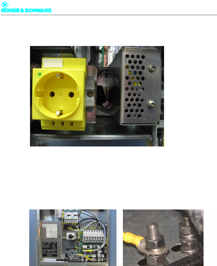
1.1.6 Optional Socket
Fig. 10 Optional socket
The optional socket is not connected with the transmitter network and must be supplied by
means of a separate power lead.
1.1.7 Grounding Bolt
Fig. 11 Grounding bolt
The grounding bolt connects the rack with the station's main grounding terminal.
Note The rack must be connected to the main grounding terminal in all cases.
Chapter 2 Design and Characteristics
2099.9595.72 - 2.10 - E-2
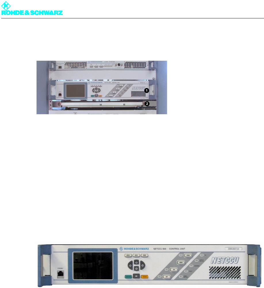
1.2 Transmitter Control Unit
Fig. 12 Equipment of the transmitter control unit
1) NETCCU
2) Rack controller
The transmitter control unit contains the following components:
NETCCU®
Rack controller
They monitor and control the transmitter to ensure that it functions properly.
1.2.1 NETCCU
Fig. 13 NETCCU
The NETCCU® 800 transmitter control unit is responsible for both internal and external
communication, including all control functions. The NETCCU® 800 shows the current status
of the transmitter system on a color display.
Note For detailed information about the NETCCU®, refer to the NETCCU® manual.
Chapter 2 Design and Characteristics
2099.9595.72 - 2.11 - E-2
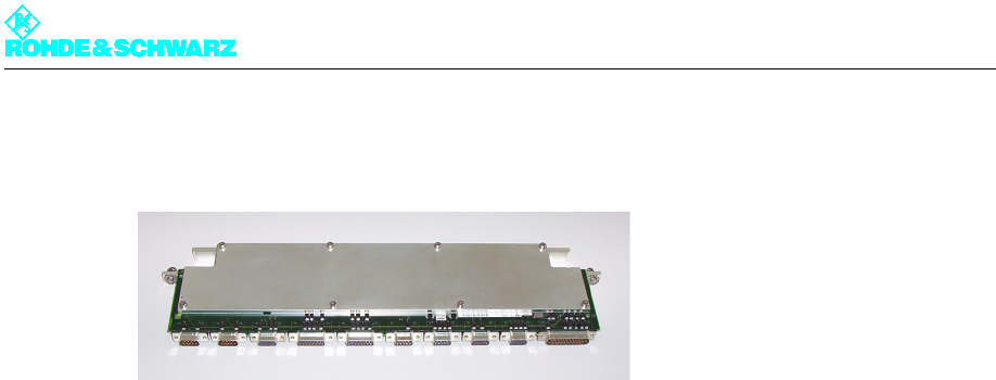
1.2.2 Rack Controller
Fig. 14 Rack controller
The rack controller is used to monitor, control and protect the transmitter rack. It handles
the following functions:
Keeps the transmitter running if the NETCCU® fails
Controls data exchange between the NETCCU® and other components via CAN bus
Monitors the outlet air temperature
Acquires measured data about the intake and outlet air temperatures
Transfers messages
Accepts and outputs rack commands (e.g. transmitter ON -> amplifier ON, cooling sys-
tem ON)
Configures the test points (mode-dependent)
Switches off the rack in the event of malfunction (e.g. fan failure)
The following equipment and modules can be connected to the rack controller:
NETCCU® via CAN-Bus
Exciter (1 or 2)
External water pump (water-cooled transmitters)
Amplifier stages (1 or 2)
Power distribution
Temperature sensors
Power test points
Note The rack controller cannot be operated directly. It is operated via the NETCCU®.