Acrodyne NW8201E DIGITAL TELEVISION BROADCAST TRANSMITTER User Manual 32 NV8202 26 04 06 01 00
Acrodyne Industries, Inc. DIGITAL TELEVISION BROADCAST TRANSMITTER 32 NV8202 26 04 06 01 00
Acrodyne >
Contents
- 1. Users Manual Part 1
- 2. Users Manual Part 2
- 3. Users Manual Part 3
- 4. Users Manual Part 4
- 5. Users Manual Part 5
- 6. Users Manual Part 6
- 7. Users Manual Part 7
- 8. Users Manual Part 8
- 9. Users Manual Part 9
- 10. Users Manual Part 10
- 11. Users Manual Part 11
- 12. USers Manual Part 12
- 13. Users Manual Part 13
- 14. Users Manual Part 14
- 15. Users Manual Part 15
- 16. Users Manual Part 16
- 17. Users Manual Part 17
- 18. Users Manual Part 18
- 19. Users Manual Part 19
- 20. Users Manual Part 20
Users Manual Part 4
Chapter 2 Design and Characteristics
2099.9595.72 - 2.12 - E-2
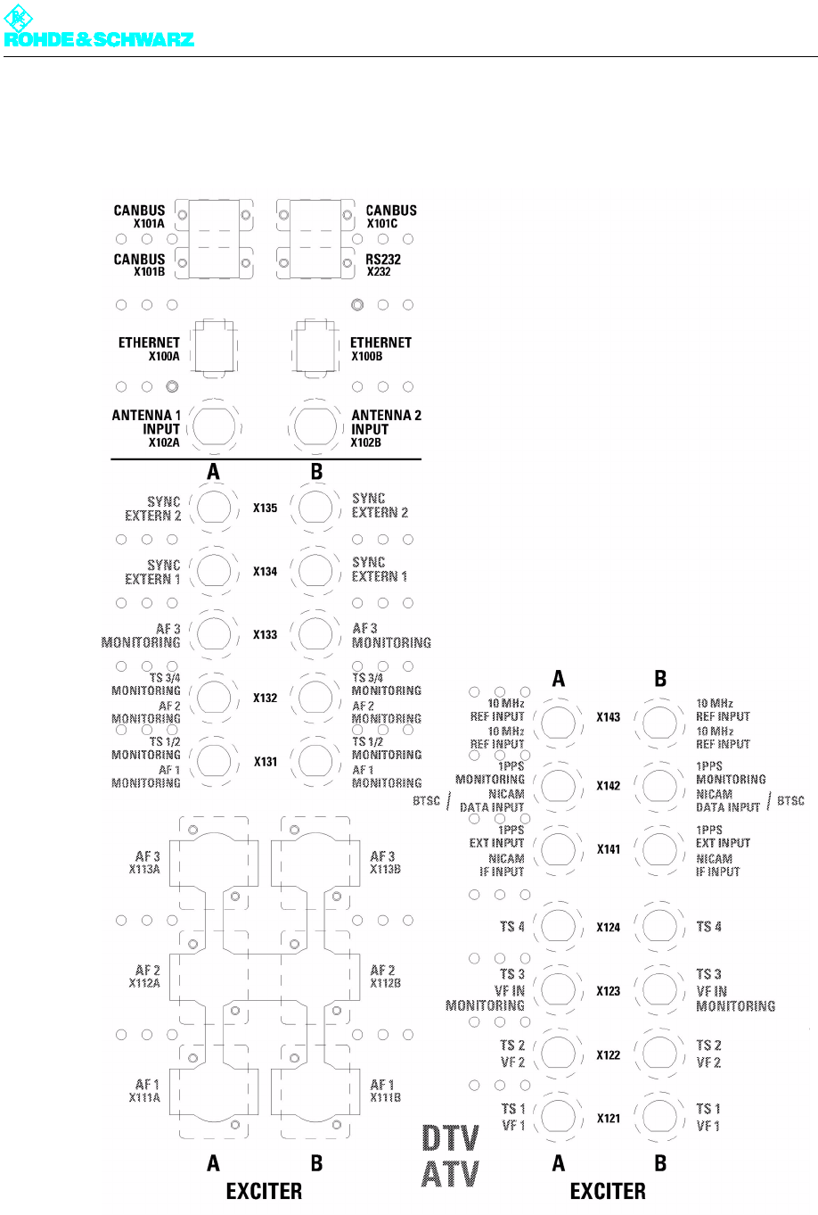
1.3 Connection Panel
Fig. 15 Connection panel
The baseband signals as well as the monitoring and remote control connections are routed
to the transmitter via the connection panel.
Chapter 2 Design and Characteristics
2099.9595.72 - 2.13 - E-2
The following table describes the connection options:
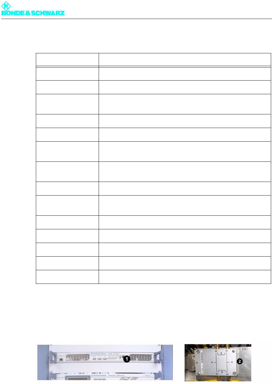
1.4 Exciter Unit
Fig. 16 Exciter unit equipment
1) Exciter SX 800
2) Exciter switch (exciter standby only)
The exciter unit contains the following components:
Connector Description
CANBUS X101A CAN bus data connection for additional racks or output stage A
CANBUS X101B CAN bus data connection for additional racks or output stage B
CANBUS X101C CAN bus data connection for external pump in the case of high-power
transmitters
RS232 X232 Serial data connection for external BITBUS interface
ETHERNET Remote LAN connector or system LAN connector, e.g. for N+1
ANTENNA 1 INPUT Antenna connector for receiver module input 1 in the NETCCU® (DTV
only)
ANTENNA 2 INPUT Antenna connector for receiver module input 2 in the NETCCU® (DTV
only)
TS1 / TS2 Transport stream inputs (digital TV)
TS3 / TS4 Additional connectors to TS1 and TS2 in the case of hierarchical cod-
ing
10 MHz REF INPUT Input for 10 MHz reference for synchronizing the output signal
1PPS MONITORING Test output 1PPS (1PPS = 1 pulse per second)
1PPS EXT INPUT Input for 1PPS signal, reference signal for DVB-T in SFN mode T
TS1/2 MONITORING Monitor output for selected TS signal of inputs 1 and 2
TS3/4 MONITORING Monitor output for selected TS signal of inputs 3 and 4
Chapter 2 Design and Characteristics
2099.9595.72 - 2.14 - E-2
Exciter
Exciter switch (in case of exciter standby)
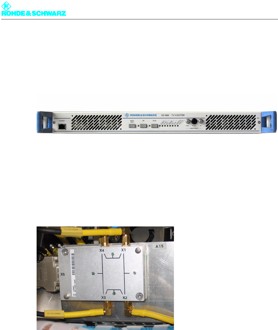
1.4.1 Exciter
Fig. 17 Exciter
The Exciter SX 800 performs all signal processing from the transport signal up to a stan-
dard-compliant RF output signal.
Note For detailed information about the exciter, refer to the exciter manual.
1.4.2 Exciter Switch
Fig. 18 Exciter switch
Note The exciter switch is included in transmitters with the exciter standby option (two exciters);
it is located behind the two exciters.
The exciter switch switches to the standby exciter in the following cases:
When the main exciter malfunctions
When manual switchover is performed via the NETCCU®
The exciter switch is controlled by the NETCCU®.