Acrodyne NW8201E DIGITAL TELEVISION BROADCAST TRANSMITTER User Manual 32 NV8202 26 04 06 01 00
Acrodyne Industries, Inc. DIGITAL TELEVISION BROADCAST TRANSMITTER 32 NV8202 26 04 06 01 00
Acrodyne >
Contents
- 1. Users Manual Part 1
- 2. Users Manual Part 2
- 3. Users Manual Part 3
- 4. Users Manual Part 4
- 5. Users Manual Part 5
- 6. Users Manual Part 6
- 7. Users Manual Part 7
- 8. Users Manual Part 8
- 9. Users Manual Part 9
- 10. Users Manual Part 10
- 11. Users Manual Part 11
- 12. USers Manual Part 12
- 13. Users Manual Part 13
- 14. Users Manual Part 14
- 15. Users Manual Part 15
- 16. Users Manual Part 16
- 17. Users Manual Part 17
- 18. Users Manual Part 18
- 19. Users Manual Part 19
- 20. Users Manual Part 20
Users Manual Part 10

Chapter 2 Design and Characteristics
2099.9595.72 - 2.32 - E-2
2 Specifications
2.1 Transmitter System in General
Frequency range ........................................ 170 MHz to 254 MHz
Voltage supply ............................................ 3 x 400 V AC ± 15%
47 Hz to 63 Hz
three-phase
Maximum installation altitude ..................... 2000 m above sea level
(over 2000 m on request)
Operating temperature range ..................... +1° C to +45° C
Max. permissible humidity .......................... 95%, noncondensing
Dimensions (W x H x D) ............................. 600 mm x 2000 mm x 800 mm
RF Connector ............................................. 15/8 EIA
Synchronization
Reference frequency .................................. 10 MHz, 0.1 V to 5 Vpp or TTL, BNC
Reference puls ........................................... 1 Hz, TTL, BNC
Operation
Local
Color display and keys .......................... Front control via graphical user interface (GUI)
RJ-45 ..................................................... Operation via PC using standard web browser
Remote
RJ45 ...................................................... IEC864-2 via Ethernet (standard)
RJ45 ...................................................... Network management interface (web server
and/or SNMP agent, optional)
Parallel I/O interface .............................. Floating contacts for messages and com-
mands (optional)
BITBUS ................................................. Bus interface in accordance with IEC 864-2
(optional)
2.2 Transmitter System - Specifically NW8202
Number of amplifiers .................................. 2
Pout ............................................................ 650 W
Air throughput............................................. At least 8.5 m3/min
Power consumption.................................... 3.2 kW ± 10%
Backup fuse................................................ 3 x 16 A
Line cross-section....................................... 2.5 mm2

Chapter 2 Design and Characteristics
2099.9595.72 - 2.33 - E-2
Total weight (approx.) ................................. 270 kg
Inputs (DVB-T/H) ........................................ 4 x ASI
Coding and modulation............................... According to EN 300744, EN 302304 (optional)
Modulation .................................................. QPSK, 16QAM or 64QAM
Guard interval ............................................. 1/4, 1/8, 1/16 or 1/32 usefull symbol period
IFFT mode .................................................. 2 k and 8 k, 4 k (optional)
Innere code rate ......................................... 1/2, 2/3, 3/4, 5/6 or 7/8
Useful symbol period .................................. 224 µs (2 k) or 896 µs (8 k),
448 µs (4 k, optional)

Broadcasting Division
2095.7346.32 - 3.0 - E-1
CHAPTER 3
INSTALLATION
Printed in Germany

Chapter 3 Installation
2099.9595.72 - 3.01 - E-2
CONTENTS
1 Equipment Supplied ........................................................................ 1
1.1 Integrated Transmitter Components ............................................................1
1.2 Transmitter Components Supplied Separately ...........................................2
2 Overview ........................................................................................... 3
3 Transmitter Setup ............................................................................ 4
3.1 Transmitter Rack Setup .................................................................................4
3.2 Transmitter Rack Alignment ..........................................................................4
3.3 Removal of Front Panels/Rear Panel ............................................................4
3.4 Unpacking of Components ............................................................................5
4 Transformer ...................................................................................... 6
5 Ventilation System ........................................................................... 7
5.1 Connection of Intake/Exhaust Ducts ............................................................7
5.2 Connection of External Backup Fan ...........................................................10
5.3 Check of Ventilation Covers ........................................................................10
5.4 Checking of Differential Pressure Gage .....................................................11
6 AC Power Supply ........................................................................... 12
6.1 Connection of Transmitter Ground .............................................................13
6.2 Connection of AC Power Cable ...................................................................13
6.3 Connection of External Equipment .............................................................15
7 Amplifiers ....................................................................................... 16
7.1 Installing the Amplifier .................................................................................16
8 Connection of Antenna/Dummy Antenna to RF Connector ...... 17
8.1 Connection of Antenna ................................................................................17
8.2 Connection of Dummy Antenna ..................................................................18
9 Connection Panel .......................................................................... 19

Chapter 3 Installation
2099.9595.72 - 3.1 - E-2
1 Equipment Supplied
1.1 Integrated Transmitter Components
When you receive the Transmitter NV820x, the following units and modules are already in-
stalled in the rack if they form part of your order:
Note Use the tables below to check that all the relevant components have been supplied.
Qty Designation Type ID
1 Cabinet rack KG830M1 2096.2002.02
1 Mid-range power distribution 2096.3009.XX
1 Control unit NETCCU®NETCCU800 2095.8007.02
1 - 2 TV exciter
Transmitter type:
NW82XXE
NW82XXV
SX800
Quantity of SX800
1
2
2095.1502.XX
1 Auxiliary power supply 1081.0254.00
1 Rack controller 2096.4505.02
2 Pressure capsule 2077.3936.00
2 Temperature sensor 2010.0006.00
2 Fan set 2096.2131.02
1 Exciter switch 2095.3257.02
1 Harmonics filter 2096.7304.02
1 Coupler/splitter unit
Transmitter type:
NW8201
NW8202
NW8203
NW8204
NW8205
NW8206
Coupler unit
none
two-way coupler BV822M1
three-way coupler BV823M1
four-way coupler BV824M1
five-way coupler BV825M1
six-way coupler BV826M1
2099.5502.02
2099.5702.02
2099.5602.02
2099.5802.02
2099.5902.02
1 Absorber unit 2096.3909.XX
1 Directional coupler with lightning
protection
GD800 2096.7204.XX

Chapter 3 Installation
2099.9595.72 - 3.2 - E-2
1.2 Transmitter Components Supplied Separately
The transmitter contains the following components that must be installed in the rack after
delivery.
Separate items
1 Strain relief for AC supply feed
Options
1 Emergency key installation kit
VAR (model): 11 = 1x pushbutton
front panel
VAR: 12 = pushbutton front and
rear panel
VAR: 13 = pushbutton rear panel
ZR800N1 2099.4506.VAR
1 Parallel remote control interface ZR800F1 3562.4210.02
1 AC transformer 115 V/200 V ZR800Z3 2099.3200.02
1 External socket kit ZR800Z1 2099.3000.02
1 Internal socket kit
VAR: 02 = 3x protective ground
contact strip
VAR: 04 = 4x protective ground
contact strip
ZR800Z2 2099.3100.VAR
1 TS distributor kit
VAR: 10 = 1x ASI distributor
VAR: 20 = 2x ASI distributor
(TS3/4)
ZR800Z4 2099.3300.VAR
Qty Designation Type ID
1 - 6 VHF amplifier VM8350A1 2097.9000.02
NX82xx accessories
consisting of:
1 Junction 13/30-7/16 2096.7004.00
2 Cover for air outlet 2096.2925.00
Qty Designation Type ID

Chapter 3 Installation
2099.9595.72 - 3.3 - E-2
2 Overview
The basic procedure for installing the transmitter is as follows:
Transmitter setup
– Set up the transmitter rack
– Align the transmitter rack
– Remove front panels/rear panel
– Unpack components
Install transformer (optional)
Ventilation system
– Connect intake/exhaust ducts
– Connect external backup fan (optional)
– Check ventilation covers
AC power supply
– Connect transmitter ground
– Connect AC power cable
– Connect external equipment
Install amplifier
Connect antenna/dummy antenna to RF connector
Program feed/remote (connection panel)
A detailed description of the installation procedure is provided in the following sections of
this chapter.
Chapter 3 Installation
2099.9595.72 - 3.4 - E-2
3 Transmitter Setup
Make sure that the transmitter is standing in a stable position and that ventilation is suffi-
cient.
Note During installation, the transmitter must be easily accessible from the front and rear. A
clearance space of at least 1.2 m is necessary in order to install all components.
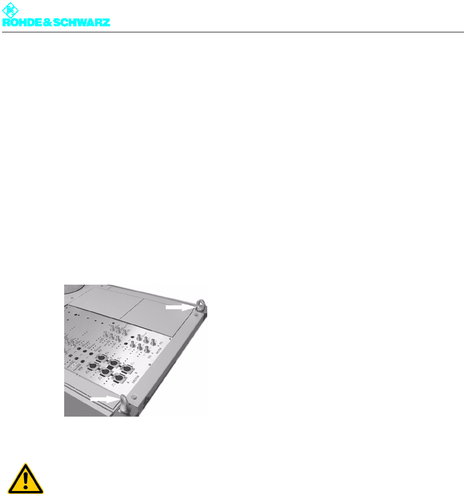
3.1 Transmitter Rack Setup
The transmitter rack can be set up using lift equipment (crane). The roof of the rack has lift
rings for this purpose.
Fig. 1 Lift rings
3.2 Transmitter Rack Alignment
The transmitter rack must be aligned vertically and horizontally to prevent distortion caused
by shearing forces. Use a spirit level to align the rack.
3.3 Removal of Front Panels/Rear Panel
Before you start installing the individual pieces of equipment, make sure that you have easy
access to all equipment, connectors and interfaces needed.
)Using a torx screwdriver, remove all front panels and the rear panel of the rack. This al-
lows you to reach all equipment, connectors and interfaces necessary.
ATTENTION!
Due to the danger of getting crushed, do not stand underneath a rack suspended in the air.
To avoid falling, take the necessary precautions when climbing ladders.

Chapter 3 Installation
2099.9595.72 - 3.5 - E-2
Note When removing and mounting the front panels and rear panel, pay special attention to the
ground terminals.
Fig. 2 Ground terminal of a front panel
3.4 Unpacking of Components
Each transmitter component is packaged separately.
)Remove the packaging and arrange all equipment so that it is ready for installation.

Chapter 3 Installation
2099.9595.72 - 3.6 - E-2
4Transformer
Note For more information about the transformer, refer to the manual on the optional AC supply
transformer.

Chapter 3 Installation
2099.9595.72 - 3.7 - E-2
5 Ventilation System
Note The ventilation system is already installed and wired inside the transmitter.
5.1 Connection of Intake/Exhaust Ducts
Depending on your specific order, the intake/exhaust openings are located at either the top
or bottom of the rack. The "external intake" option may also be available. In this case, the
air intake is routed to the output box via an integrated air filter on the rear panel.
The external pressure drop must not exceed 100 Pa for the required amount (e.g. for
NV8206, 6 amplifiers: 17 m2/min).
Thus, a total of max. 12 m tubing (D = 250 mm), two 90° arcs and an air filter with a final
pressure drop of 40 Pa can be used.
Note Only tubing with a diameter of 250 mm is permissible.
If air intake is directly from outside the building, use an air filter.
Note Be sure to connect the intake and exhaust lines properly, otherwise the system may be-
come overheated.
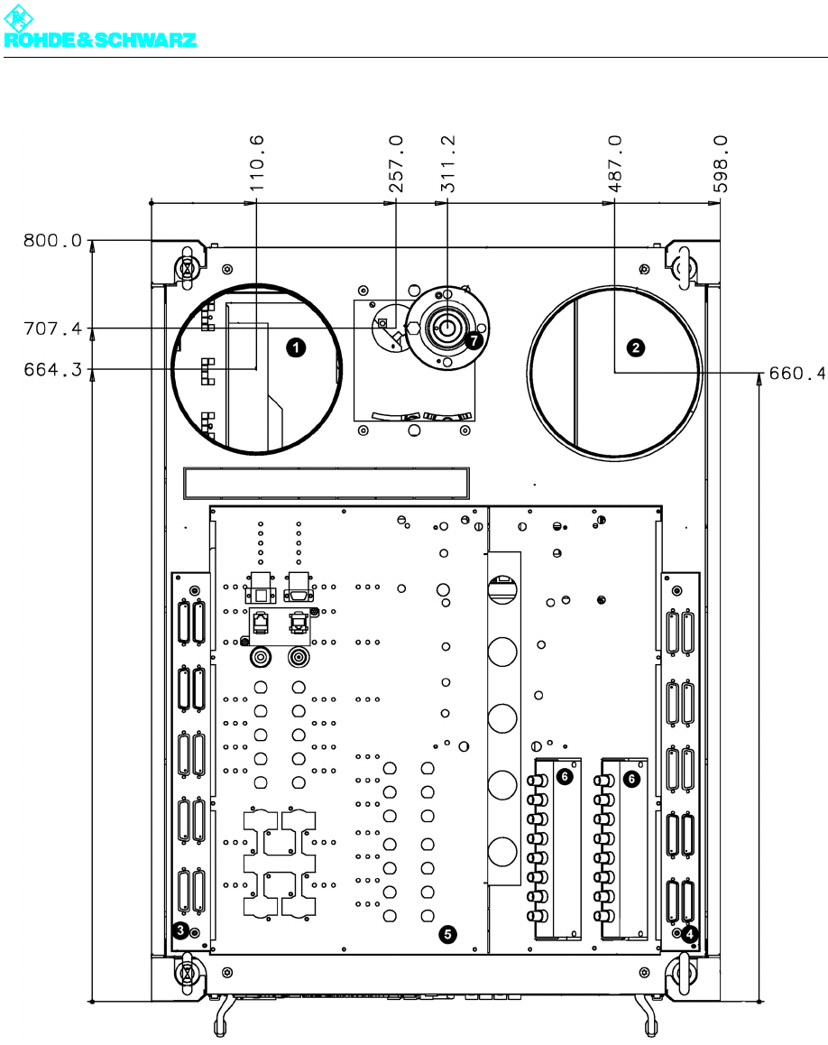
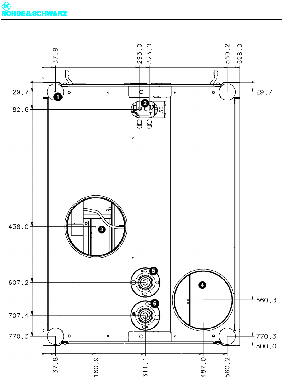
The following drawings show the transmitter roof and floor dimensioning for properly con-
necting the transmitter to the station.
ATTENTION!
The temperature of the cooling air must not drop below the dew point, otherwise conden-
sation may occur in the air shafts.
Chapter 3 Installation
2099.9595.72 - 3.8 - E-2
Fig. 3 Transmitter roof dimensioning
1) Intake (flange Ø178)
2) Exhaust (flange Ø178)
3) Remote interface
4) Remote interface (optional)
5) Transmitter connection panel
6) ASI distributor
7) RF output (1 5/8 EIA)
Chapter 3 Installation
2099.9595.72 - 3.9 - E-2
Fig. 4 Transmitter floor dimensioning
1) Adjustable foot (Ø 50)
2) AC supply input
3) Bottom intake (flange Ø178)
4) Bottom exhaust (flange Ø178)
5) Bottom RF output (ATV, 1 5/8 EIA))
6) Bottom RF output (DVB, 1 5/8 EIA))
Chapter 3 Installation
2099.9595.72 - 3.10 - E-2
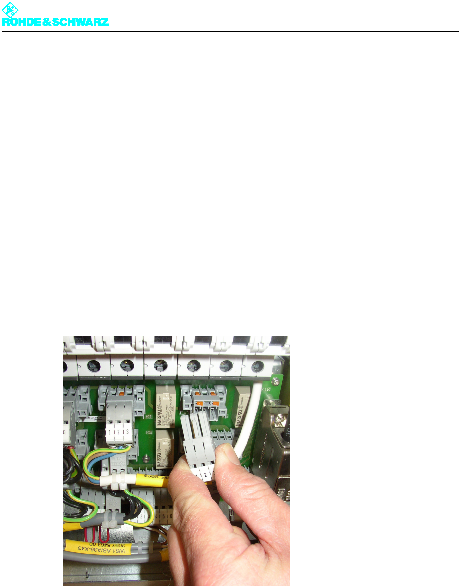
5.2 Connection of External Backup Fan
Note If longer distances (more than 12 m) are involved on-site, an external fan should be used.
The transmitter offers a switched phase for controlling an external AC supply relay. In addi-
tion, you can insert an external protective motor switch with release contact in the transmit-
ter's cooling fault detection circuit if necessary.
Switched phase for external fan
X33.1 = L (overcurrent protector 3A)
X33.2 = N
X33.3 = PE
Overcurrent (external cooling)
44.1
44.2
Fig. 5 Plug for connecting an external fan
5.3 Check of Ventilation Covers
To ensure that ventilation functions properly inside the transmitter, the interior part of the
transmitter rack has an opening on each side to permit air circulation.
)Make sure that the ventilation covers on the slots in the frame where the amplifiers will
be fitted are open on both sides. Remove the covers if necessary.
Chapter 3 Installation
2099.9595.72 - 3.11 - E-2
Fig. 6 Ventilation opening
Note The ventilation openings on vacant slots (without amplifiers) have to be closed.
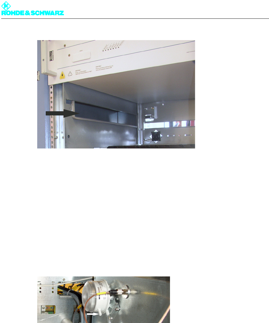
5.4 Checking of Differential Pressure Gage
For the differential pressure gages to be able to measure the pressure between the fans
and the environment, the covers must be removed.
)Make sure that the covers of both differential pressure gages on the left side have been
removed.
Fig. 7 Differential pressure gage without cover