Acrodyne NW8201E DIGITAL TELEVISION BROADCAST TRANSMITTER User Manual 32 NV8202 26 04 06 01 00
Acrodyne Industries, Inc. DIGITAL TELEVISION BROADCAST TRANSMITTER 32 NV8202 26 04 06 01 00
Acrodyne >
Contents
- 1. Users Manual Part 1
- 2. Users Manual Part 2
- 3. Users Manual Part 3
- 4. Users Manual Part 4
- 5. Users Manual Part 5
- 6. Users Manual Part 6
- 7. Users Manual Part 7
- 8. Users Manual Part 8
- 9. Users Manual Part 9
- 10. Users Manual Part 10
- 11. Users Manual Part 11
- 12. USers Manual Part 12
- 13. Users Manual Part 13
- 14. Users Manual Part 14
- 15. Users Manual Part 15
- 16. Users Manual Part 16
- 17. Users Manual Part 17
- 18. Users Manual Part 18
- 19. Users Manual Part 19
- 20. Users Manual Part 20
Users Manual Part 9
Chapter 2 Design and Characteristics
2099.9595.72 - 2.25 - E-2
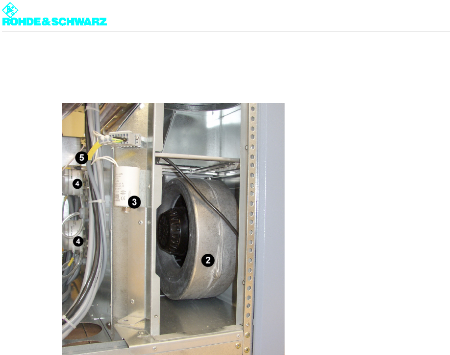
1.9 Cooling system
Fig. 30 Cooling system
1) Air intake duct
2) Fan
3) Starting capacitor
4) Differential pressure gage
5) Temperature sensor
The cooling system with its two integrated fans (active standby) prevents the transmitter
from overheating and contains the following components:
Air intake/exhaust duct
Fans (2)
Starting capacitor (2)
Differential pressure gages (2)
Temperature sensors (2)
Chapter 2 Design and Characteristics
2099.9595.72 - 2.26 - E-2
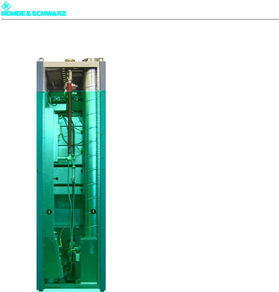
1.9.1 Air Intake/Exhaust Duct
Fig. 31 Air intake duct (1) and exhaust duct (2)
The air from the intake duct is drawn in by the fans and forwarded to the distribution shaft.
The distribution shaft provides enough air to each amplifier to cool it. The heated air is rout-
ed to an air collecting shaft on the opposite site of the amplifier and expelled via the exhaust
duct.
Note The intake/exhaust outputs are located either on the top or bottom of the rack, depending
on your order specifications.
If the intake is at the bottom, there is no intake duct. The connecting flange is located di-
rectly beneath the output box.
In addition, the absorber unit is situated at the bottom and it feeds into the exhaust connec-
tion.
Chapter 2 Design and Characteristics
2099.9595.72 - 2.27 - E-2
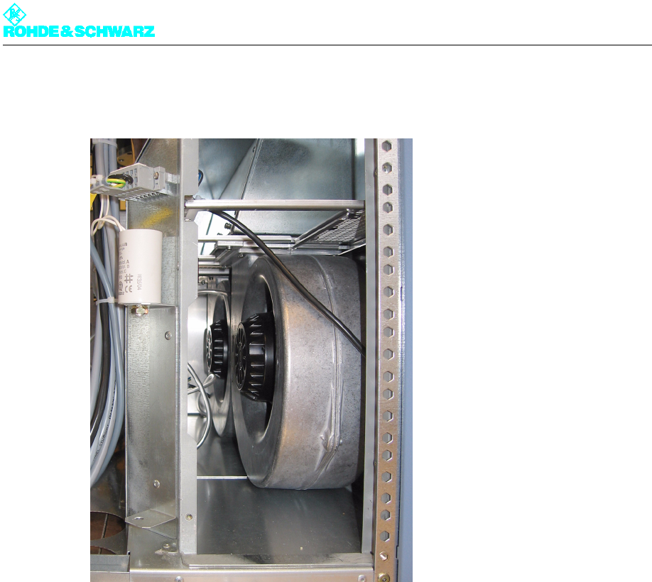
1.9.2 Fans
Fig. 32 Fans
A standard transmitter rack contains two fans, which adequately cool the transmitter with
air. If one of the fans is defective, a warning is sent to the controller but the transmitter con-
tinues to operate. If both fans fail, the rack controller switches off the affected rack. The
transmitter indicates a cooling malfunction.
Chapter 2 Design and Characteristics
2099.9595.72 - 2.28 - E-2
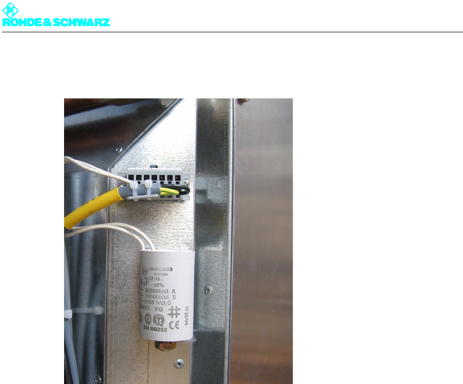
1.9.3 Starting Capacitor
Fig. 33 Starting capacitor
Each motor is equipped with an external starting capacitor.
Chapter 2 Design and Characteristics
2099.9595.72 - 2.29 - E-2
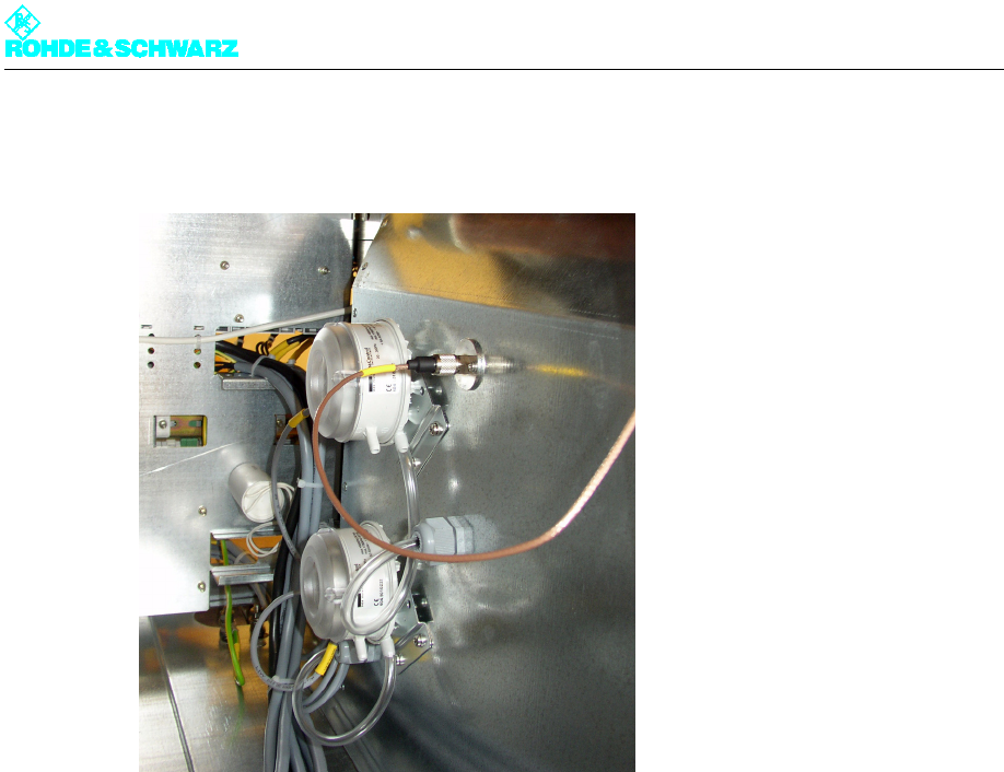
1.9.4 Differential Pressure Gage
Fig. 34 Differential pressure gage
The differential pressure gages (diaphragm switches) measure the differential pressure of
each fan between the fan flange (output) and the environment. Thus, fan malfunctions can
be selectively sent to the transmitter control unit.

Chapter 2 Design and Characteristics
2099.9595.72 - 2.30 - E-2
1.9.5 Temperature Sensors
Fig. 35 Temperature sensors
The temperature sensors measure the absolute intake and exhaust temperature in °C for
display on the NETCCU® and for monitoring in the rack controller.
Note If the exhaust temperature is higher than 65 °C, the rack controller switches the rack off due
to the danger of overheating.
Chapter 2 Design and Characteristics
2099.9595.72 - 2.31 - E-2
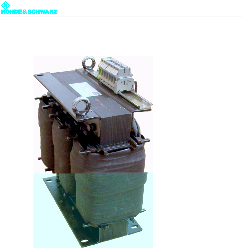
1.10 Transformer
Fig. 36 Transformer
The transformer converts the voltage in the event of local voltage differences, e.g. in the
United States or Canada (AC power supply 115 V/200 V).
Note For detailed information about the transformer, refer to the transformer manual.