Acrodyne NW8201E DIGITAL TELEVISION BROADCAST TRANSMITTER User Manual 32 NV8202 26 04 06 01 00
Acrodyne Industries, Inc. DIGITAL TELEVISION BROADCAST TRANSMITTER 32 NV8202 26 04 06 01 00
Acrodyne >
Contents
- 1. Users Manual Part 1
- 2. Users Manual Part 2
- 3. Users Manual Part 3
- 4. Users Manual Part 4
- 5. Users Manual Part 5
- 6. Users Manual Part 6
- 7. Users Manual Part 7
- 8. Users Manual Part 8
- 9. Users Manual Part 9
- 10. Users Manual Part 10
- 11. Users Manual Part 11
- 12. USers Manual Part 12
- 13. Users Manual Part 13
- 14. Users Manual Part 14
- 15. Users Manual Part 15
- 16. Users Manual Part 16
- 17. Users Manual Part 17
- 18. Users Manual Part 18
- 19. Users Manual Part 19
- 20. Users Manual Part 20
Users Manual Part 19
Chapter 8 Service
2099.9595.72 - 8.26 - E-2
8 Harmonics Filter
In the Transmitter Family NW820x the harmonics filter is integrated into the RF line.
8.1 Replacing the Harmonics Filter
Note The harmonics filter is lacquered in order to reduce the surface temperature, but high tem-
peratures are nevertheless to be expected.
8.1.1 Removing the Harmonics Filter
Note The harmonics filter is connected to the RF chain by means of two rigid line brackets. So
that the inner line of the lower rigid line (into the bandpass) stays fixed in place, the tension-
ing clamp of the lower rigid line bracket should be opened first.
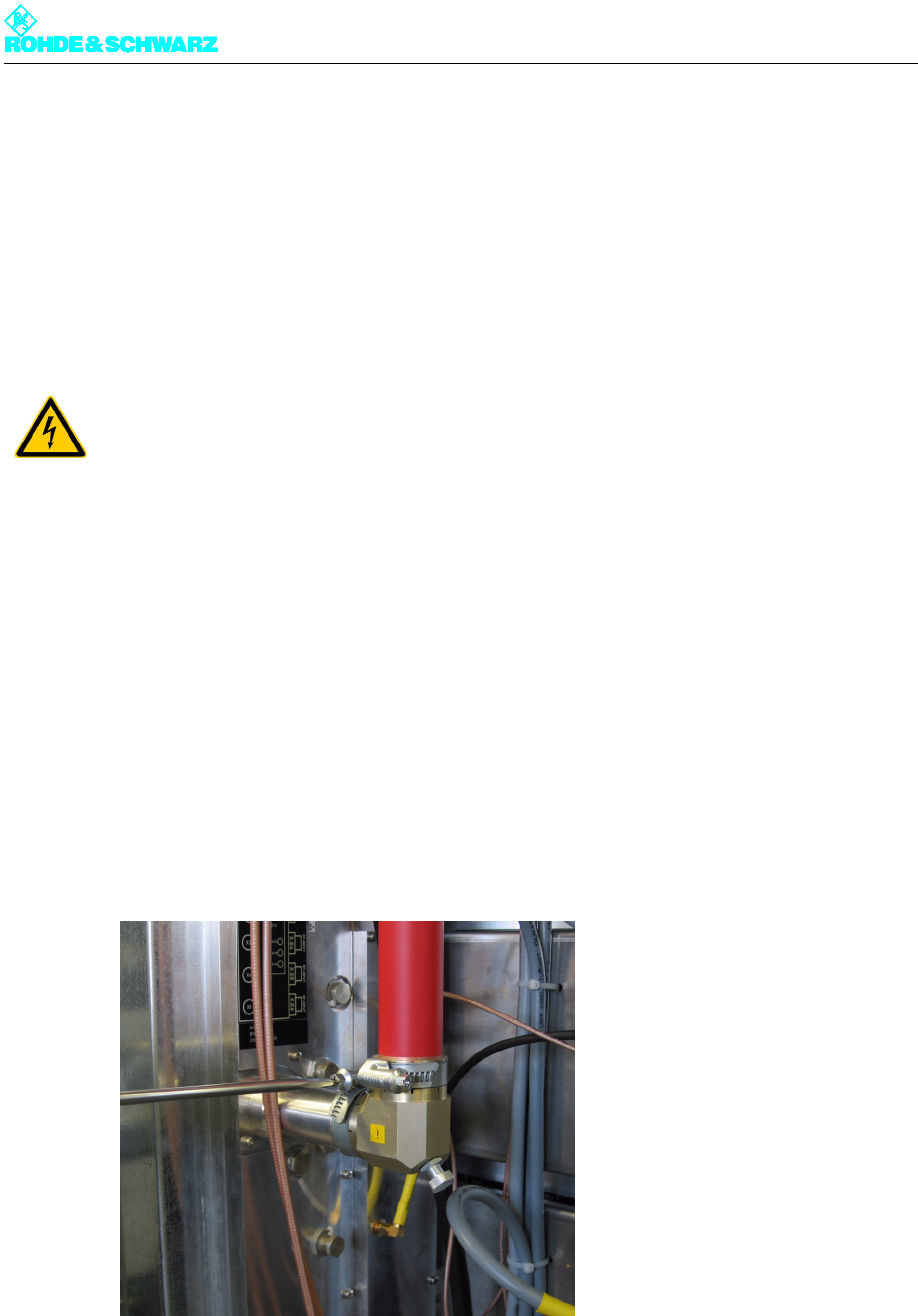
To remove the harmonics filter proceed as follows:
1. Open the tensioning clamp of the lower rigid line bracket on the rigid connection of the
combiner.
2. Open the tensioning clamp of the upper rigid line bracket using an open-end wrench
No. 7 or a Phillips screwdriver No. 2.
3. Pull the harmonics filter of the combiner rigid line down and to the right.
4. Pull the harmonics filter downward from the upper rigid line bracket.
ATTENTION!
Always make sure that the power supply is disconnected before commencing any service
work on the transmitter rack; this will prevent injury caused by electric shock and damage
to the instruments.
Chapter 8 Service
2099.9595.72 - 8.27 - E-2
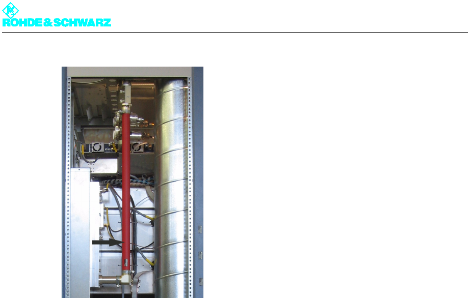
Fig. 17 Removing the harmonics filter
8.1.2 Installing the Harmonics Filter
The replacement harmonics filter has no rigid line brackets.
)Remove the rigid line bracket from the old harmonics filter, attach the bracket to the new
harmonics filter (top) and screw it firmly in place.
To install the unit in the transmitter, reverse the procedure used to remove it.

Chapter 8 Service
2099.9595.72 - 8.28 - E-2
9 Cooling System
You can replace the following cooling system components:
Fan
Starting capacitor
Differential pressure gage
Temperature sensors
9.1 Replacing the Fan
The transmitter rack contains two fans as standard; one of these can be reached only from
the front and the other only from the back. However the removal sequence is the same in
both cases.
9.1.1 Removing the Fan
Note Prior to removal make sure which of the two fans needs to be replaced.
1. Using a Torx screwdriver No. 20, remove the front panel of the power distribution to re-
place the front fan, or the rear panel of the transmitter to replace the rear fan.
2. Switch off automatic line fuse F6 (rear fan) or F7 (front fan).
Note Wait two minutes before starting to remove the fan (to allow for the fan overrun time).
3. Undo the four screws on the fan housing and remove the cover.
ATTENTION!
Always make sure that the power supply is disconnected before commencing any service
work on the transmitter rack; this will prevent injury caused by electric shock and damage
to the instruments.
Chapter 8 Service
2099.9595.72 - 8.29 - E-2
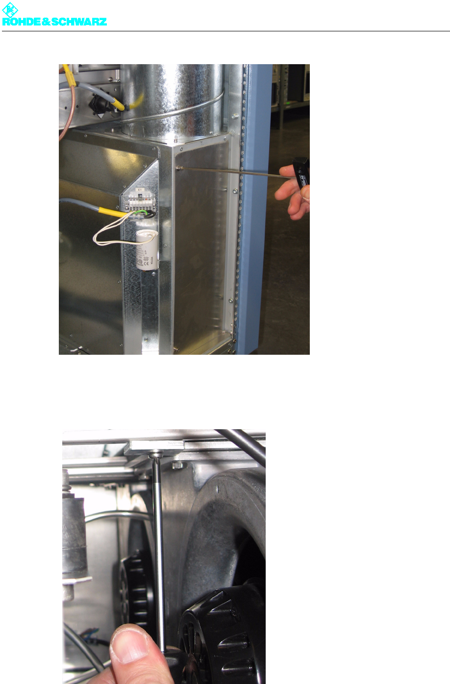
Fig. 18 Undoing the screws from the fan housing
4. On the upper side of the fan housing is a retaining device that must be unscrewed using
a Torx screwdriver No. 20.
Fig. 19 Unscrewing the retaining device
5. Pull the power cable out of the connector and take away the air tube.
Chapter 8 Service
2099.9595.72 - 8.30 - E-2
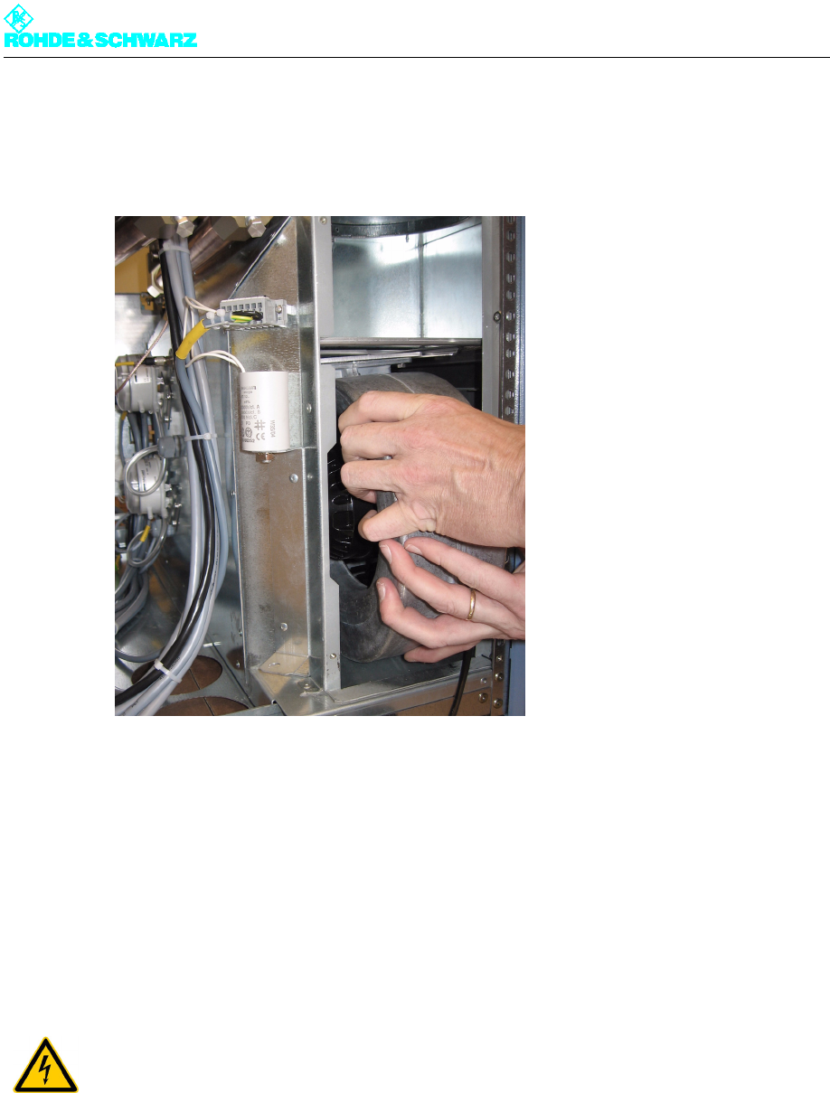
6. Slide the fan slightly to the side, then pull it toward yourself and out of the fan housing.
The fan is easy to remove due to the guide rails
Fig. 20 Removing a fan
9.1.2 Installing the Fan
To install the unit in the transmitter, reverse the procedure used to remove it.
9.2 Replacing the Starting Capacitor
9.2.1 Removing the Starting Capacitor
Note Prior to removal make sure which of the two starting capacitors needs to be replaced.
ATTENTION!
Always make sure that the power supply is disconnected before commencing any service
work on the transmitter rack; this will prevent injury caused by electric shock and damage
to the instruments.
Chapter 8 Service
2099.9595.72 - 8.31 - E-2
1. Using a Torx screwdriver No. 20, remove the front panel of the power distribution to re-
place the front starting capacitor, or the rear panel of the transmitter to replace the rear
starting capacitor.
2. Switch off automatic line fuse F6 (fan 1, rear starting capacitor) or F7 (fan 2, front starting
capacitor).
3. Remove the fan connector.
4. Undo the nut (M8, wrench width 13 mm) on the face plate of the capacitor.
5. Cut off the cable ties to free the cable.
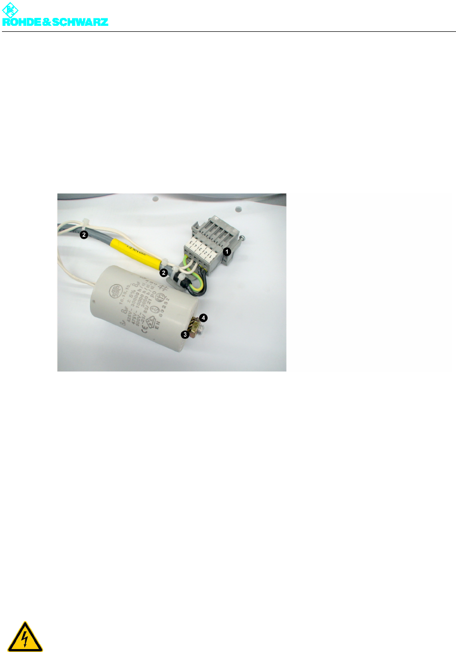
Fig. 21 Removing the starting capacitor
1) Connector (and socket)
2) Cable ties
3) Lock washer
4) Nut (M8)
9.2.2 Installing the Starting Capacitor
To install the unit in the transmitter, reverse the procedure used to remove it.
Note The lock washer and M8 nut must be fastened together again.
9.3 Replacing the Differential Pressure Gage
ATTENTION!
Always make sure that the power supply is disconnected before commencing any service
work on the transmitter rack; this will prevent injury caused by electric shock and damage
to the instruments.
Chapter 8 Service
2099.9595.72 - 8.32 - E-2
9.3.1 Removing the Differential Pressure Gage
Note Prior to removal make sure which of the two differential pressure gages needs to be re-
placed.
1. Using a Torx screwdriver No. 20, remove the rear panel of the rack.
2. Remove the air connector (plastic tube).
3. Disconnect the associated cable from the connector on X45 of the power distribution
board. (Pins 1 and 2 for differential pressure gage 1 or pins 3 and 4 for differential pres-
sure gage 2.)
4. Cut off the cable ties to free the cable.
5. Undo the two screws on the bracket.
6. Remove the differential pressure gage.
7. Unscrew the round cover and remove the cable (6.3 mm connector).
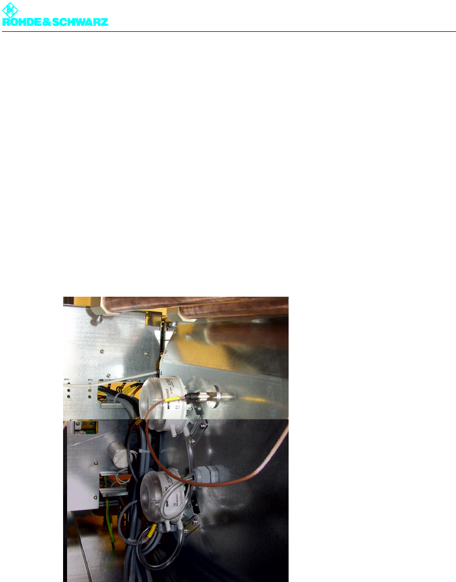
Fig. 22 Removing the differential pressure gage
9.3.2 Installing the Differential Pressure Gage
To install the unit in the transmitter, reverse the procedure used to remove it.
)Check whether the protective cap for the air nozzle on the left-hand differential pressure
gage has already been removed and if not, remove it (see figure).
Chapter 8 Service
2099.9595.72 - 8.33 - E-2
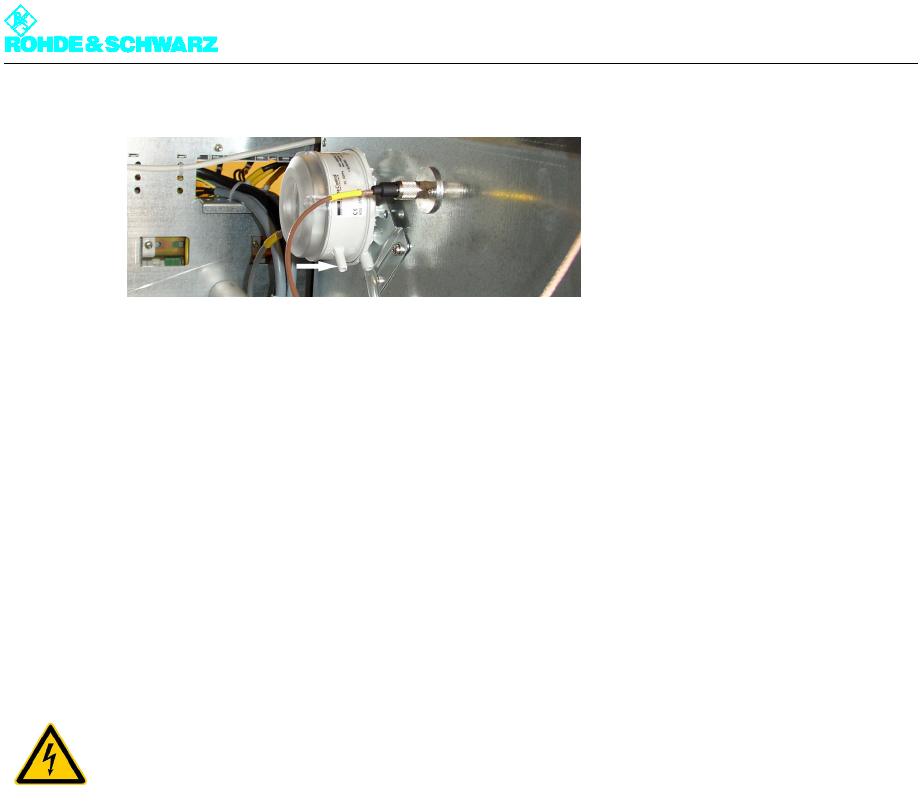
Fig. 23 Differential pressure gage without protective cap
Note After installation the differential pressure gage must be set to the switching point of 200 Pa
again.
1. Remove the transparent top cover.
In the middle is an adjuster with a scale.
2. Use a screwdriver to turn the adjuster until the arrow points to the value 200.
9.4 Replacing Temperature Sensors
The transmitter rack contains two temperatur sensors which measure the intake and outlet
air temperatures. They are located on the intake and outlet lines on the rack.
9.4.1 Removing a Temperature Sensor
Note Prior to removal make sure which of the two temperature sensors needs to be replaced.
1. Using a Torx screwdriver No. 20, remove the rear panel of the rack.
2. Unplug the connector of the temperature sensor concerned.
ATTENTION!
Always make sure that the power supply is disconnected before commencing any service
work on the transmitter rack; this will prevent injury caused by electric shock and damage
to the instruments.
Chapter 8 Service
2099.9595.72 - 8.34 - E-2
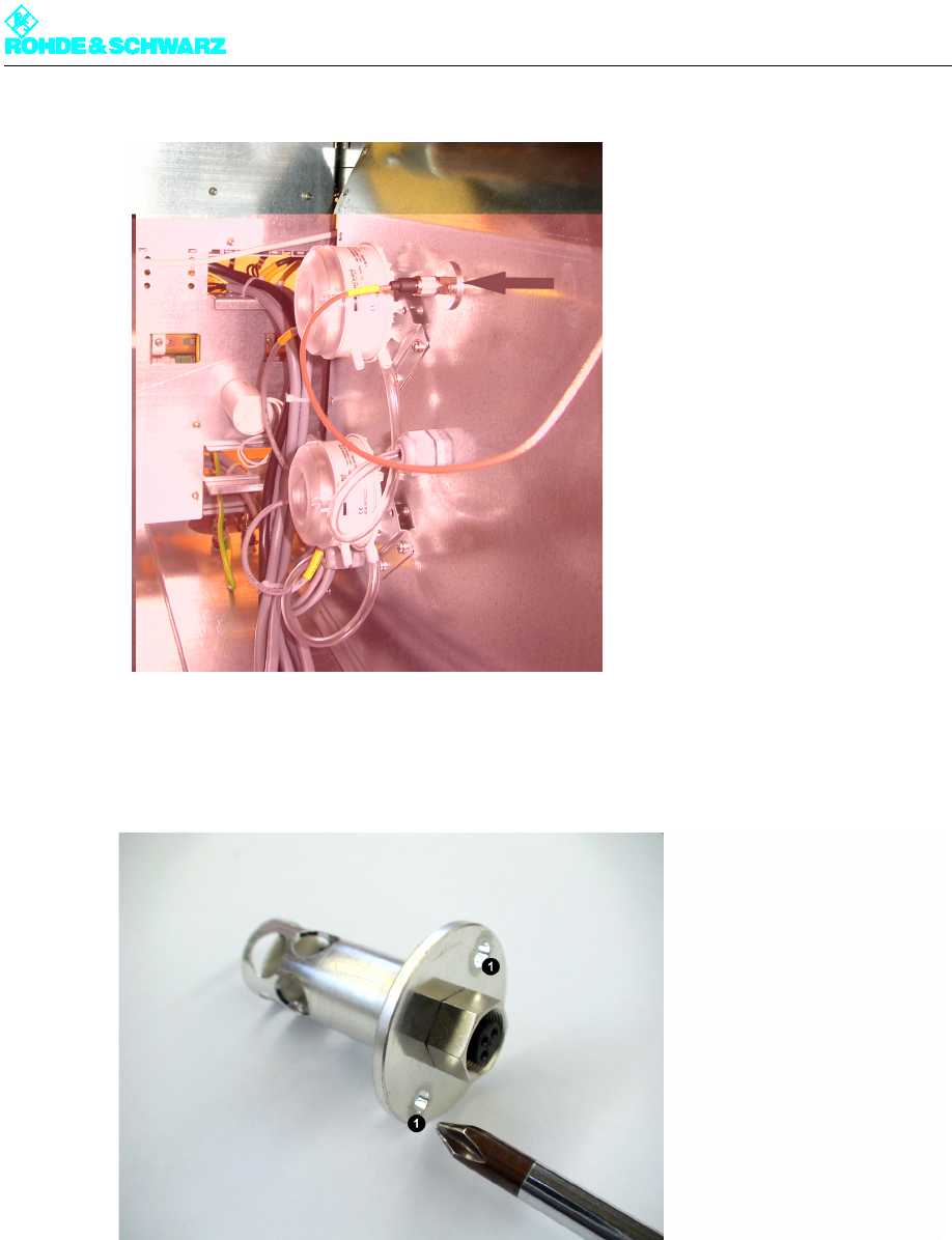
Fig. 24 Removing the temperature sensor
3. Using a Phillips screwdriver No. 0, undo the two screws (M3) on the temperature sensor
flange.
1) Openings for fixing screws (M3)
4. Carefully remove the temperature sensor from the aperture in the air duct.
9.4.2 Installing a Temperature Sensor
To install the unit in the transmitter, reverse the procedure used to remove it.

Chapter 8 Service
2099.9595.72 - 8.35 - E-2
10 Transformer
Note For more information about the transformer, refer to the manual on the optional AC supply
transformer.