Acrodyne NW8201E DIGITAL TELEVISION BROADCAST TRANSMITTER User Manual 32 NV8202 26 04 06 01 00
Acrodyne Industries, Inc. DIGITAL TELEVISION BROADCAST TRANSMITTER 32 NV8202 26 04 06 01 00
Acrodyne >
Contents
- 1. Users Manual Part 1
- 2. Users Manual Part 2
- 3. Users Manual Part 3
- 4. Users Manual Part 4
- 5. Users Manual Part 5
- 6. Users Manual Part 6
- 7. Users Manual Part 7
- 8. Users Manual Part 8
- 9. Users Manual Part 9
- 10. Users Manual Part 10
- 11. Users Manual Part 11
- 12. USers Manual Part 12
- 13. Users Manual Part 13
- 14. Users Manual Part 14
- 15. Users Manual Part 15
- 16. Users Manual Part 16
- 17. Users Manual Part 17
- 18. Users Manual Part 18
- 19. Users Manual Part 19
- 20. Users Manual Part 20
Users Manual Part 11
Chapter 3 Installation
2099.9595.72 - 3.12 - E-2
6 AC Power Supply
All standard components of the Transmitter NV820x are interconnected by wires. Thus, the
rack merely needs to be connected to one AC power supply.
Requirements
AC supply voltage - three-phase current 230 V/400 V ± 15%
AC supply frequency - 47 Hz to 63 Hz
*) without optional equipment
ATTENTION!
Before you connect the transmitter, disconnect the power supply cable from the supply.
ATTENTION!
Make sure that the AC supply voltage is within the specified range and check all power
cables for possible damage.
System type
Power consumption *
± 10% (frequency-depen-
dent)
Backup fuse Line cross-
section Max. currents
NW8201 1.8 kW 3 x 16 A 2.5 mm2
L1: 3.6 A
L2: 2.1 A
L3: 2.6 A
NW8202 3.2 kW 3 x 16 A 2.5 mm2
L1: 5.5 A
L2: 4.3 A
L3: 4.6 A
NW8203 4.6 kW 3 x 16 A 2.5 mm2
L1: 7.6 A
L2: 6.5 A
L3: 6.8 A
NW8204 5.9 kW 3 x 20 A 4.0 mm2
L1: 9.5 A
L2: 8.7 A
L3: 8.9 A
NW8205 7.3 kW 3 x 20 A 4.0 mm2 L1: 11.4 A
L2: 10.5 A
L3: 10.8 A
NW8206 8.7 kW 3 x 20 A 4.0 mm2 L1: 13.4 A
L2: 12.6 A
L3: : 12.8 A
Chapter 3 Installation
2099.9595.72 - 3.13 - E-2
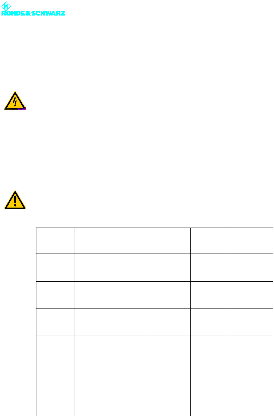
6.1 Connection of Transmitter Ground
A grounding bolt is located on the bottom of the transmitter rack, well accessible from the
front.
)Secure the external ground conductor to the grounding bolt using the ground nut.
Fig. 8 Ground connection on transmitter rack
6.2 Connection of AC Power Cable
The external AC power supply is connected directly to the main switch. The main switch
completely isolates the rack from the AC supply. Use a five-wire cable (3 phases, neutral
and PE conductor)
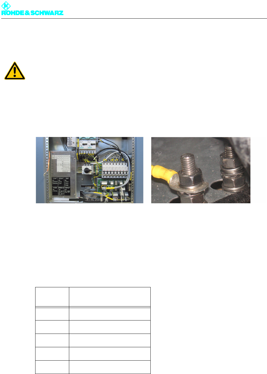
1. Unscrew the rotary switch and the cover of the main switch.
ATTENTION!
The rack must be connected to the station's main ground terminal.
AC power
supply Main switch Q1
L1 Q1.T1
L2 Q1.T2
L3 Q1.T3
NQ1.N
PE Ground terminal X.PE1
Chapter 3 Installation
2099.9595.72 - 3.14 - E-2
Fig. 9 Unscrew rotary switch and cover.
2. Secure the supplied strain relief for the AC supply cable in place as shown.
Fig. 10 Strain relief for the AC supply cable
3. Loosen the locking screws on the switch housing so that you can easily insert the ca-
bles.
4. Insert the cables into the corresponding openings and fasten them in place with screws.
5. Using a phase-sequence indicator, determine the phase sequence of the rotating field
(should be clockwise).
If the phase sequence is correct, continue to the next step. If the phase sequence is not
correct, reverse the cables and measure the phase sequence again.
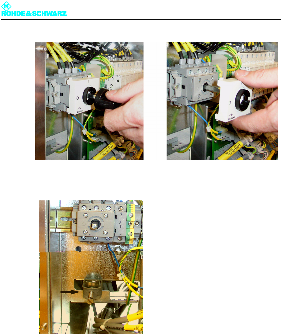
6. Remount cover and rotary switch with screws.
Chapter 3 Installation
2099.9595.72 - 3.15 - E-2
Fig. 11 Main switch connection
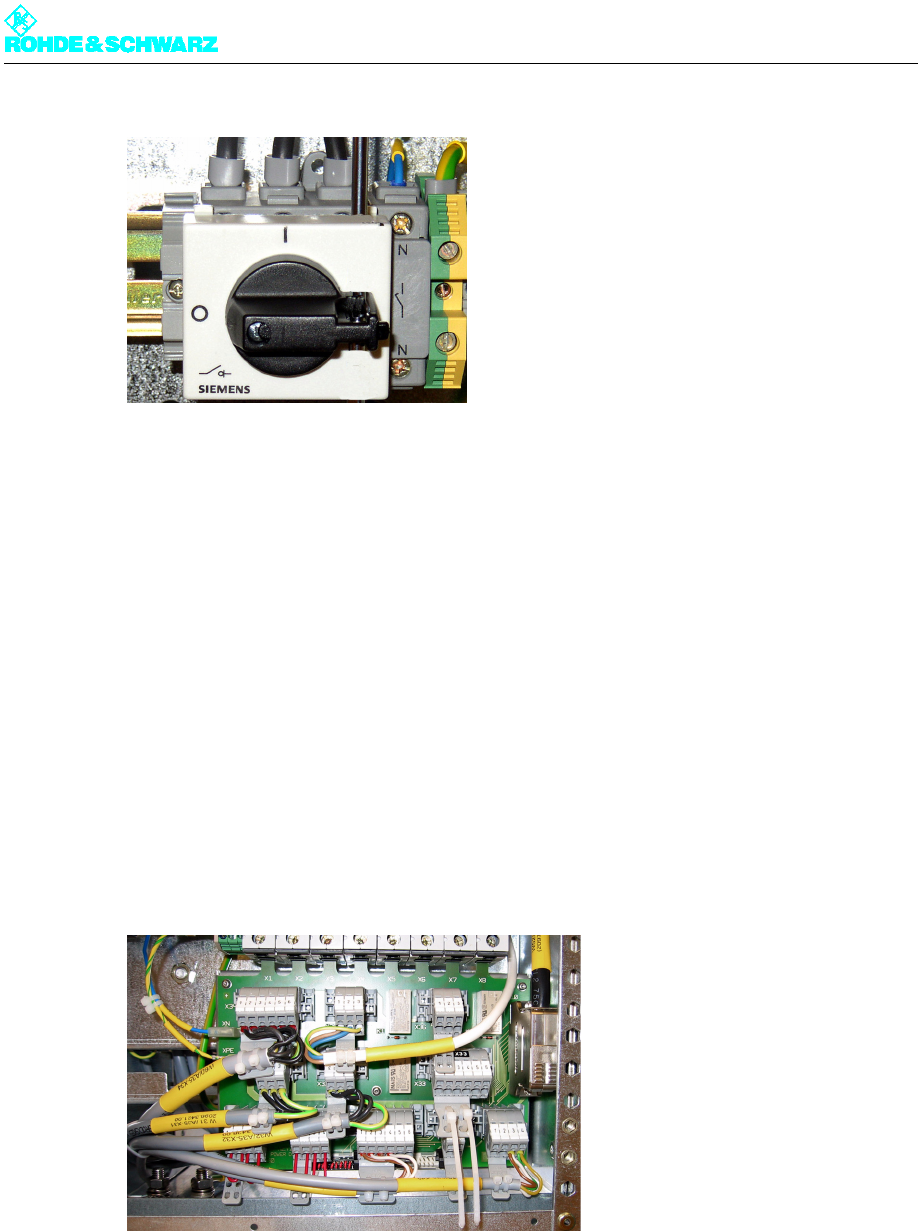
6.3 Connection of External Equipment
You can connect the following equipment to the transmitter's power distribution board:
External fan
External dummy antenna
The exact dummy plugs needed are already installed in the proper positions.
1. Remove the required dummy plug from the power distribution board.
2. Connect the cables of the external equipment to the plug.
3. Reinsert the plug in the power distribution board.
Fig. 12 Power distribution board with plugs.
Chapter 3 Installation
2099.9595.72 - 3.16 - E-2
7Amplifiers
When the transmitter is shipped from the factory, one or two exciters and an NETCCU® are
already mounted in the rack. In contrast, the amplifiers must be installed in the rack later.
7.1 Installing the Amplifier
Note Before installing the amplifier, make sure that the ventilation covers on the amplifier slots
provided in the frame are open on both sides. Remove the covers if necessary.
Install the amplifiers in the sequence top to bottom.
1. Carefully remove the amplifier from its packaging.
2. Select the installation position provided for the amplifier in the transmitter rack.
3. Place the amplifier on the guide rails and slide it carefully into the rack as far as it will go.
The amplifier is taken to the connections by means of guide pins on the rear panel.
4. Fasten the amplifiers in place using the four screws of the two front brackets on the rack.
5. To install additional amplifiers, repeat steps 1 through 4.
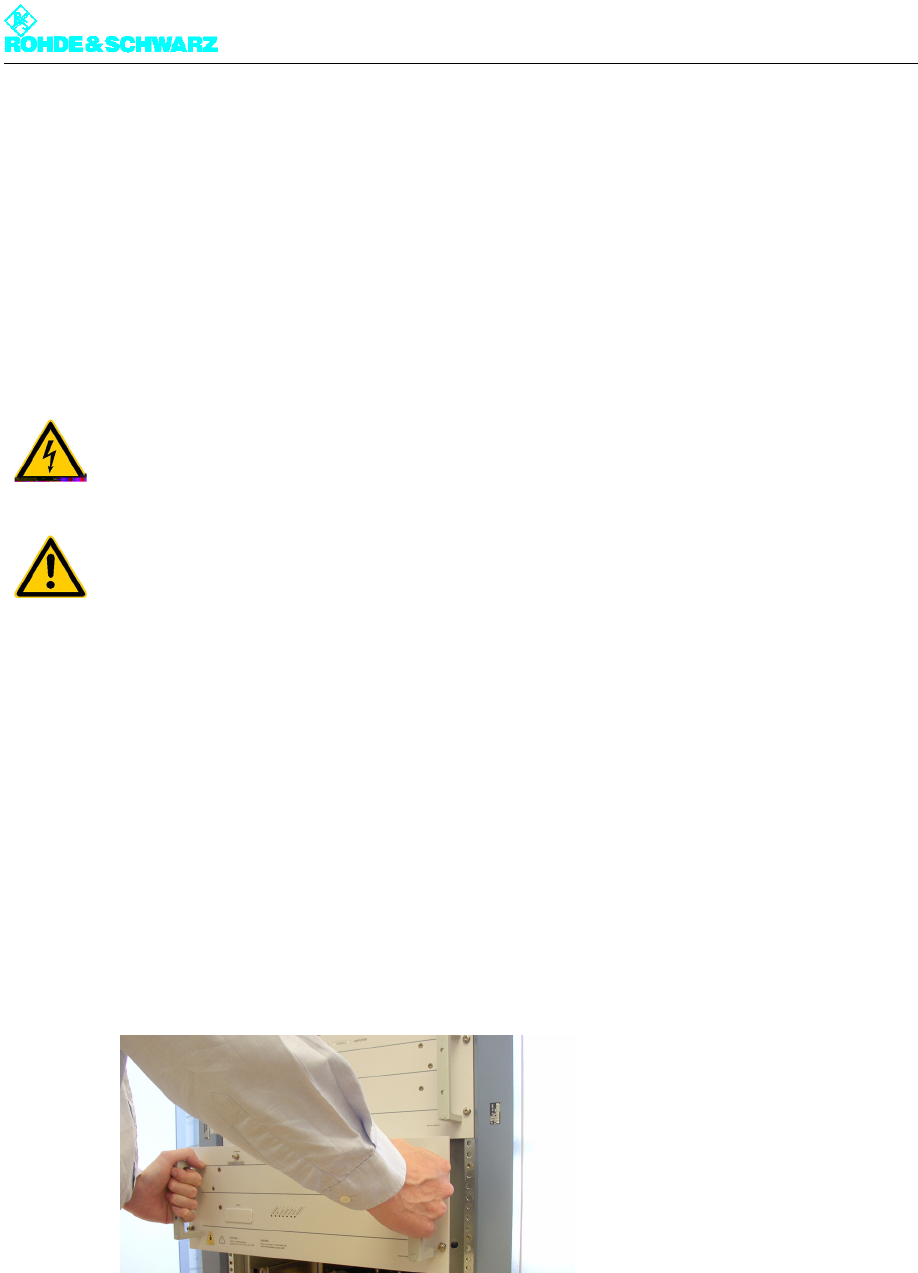
Fig. 13 Installing the amplifier
ATTENTION!
Always make sure that the power supply is disconnected before commencing any installa-
tion work on the transmitter rack; this will prevent injury from electric shock and damage to
the equipment.
ATTENTION!
Always install the amplifiers in pairs since they are quite heavy (approx. 25 kg).

Chapter 3 Installation
2099.9595.72 - 3.17 - E-2
8 Connection of Antenna/Dummy Antenna to RF
Connector
The connection flanges for the antenna cables are uniformly 1 5/8" EIA for 325 W to 1.95 kW
TV transmitters; they are located on the roof of the transmitter. Depending on the transmit-
ter station (one or more transmitters), either the antenna (RF cable or RF transmission line)
or an RF connection is connected directly to a multi-transmitter combining filter.
8.1 Connection of Antenna
Connect the antenna as follows:
)Using the four screws (M8, 35 mm), fasten the ready-made coaxial cable located on the
station in place. To prevent the screw connection from locking in place, insert a plain
washer and spring-lock washer.
Note In regions with high humidity, the supplied rubber ring can be inserted in the groove be-
tween the two EIA flanges.
ATTENTION!
Do not connect the antenna until you have completed all measurements, because the link
to the antenna produces emissions.
Chapter 3 Installation
2099.9595.72 - 3.18 - E-2
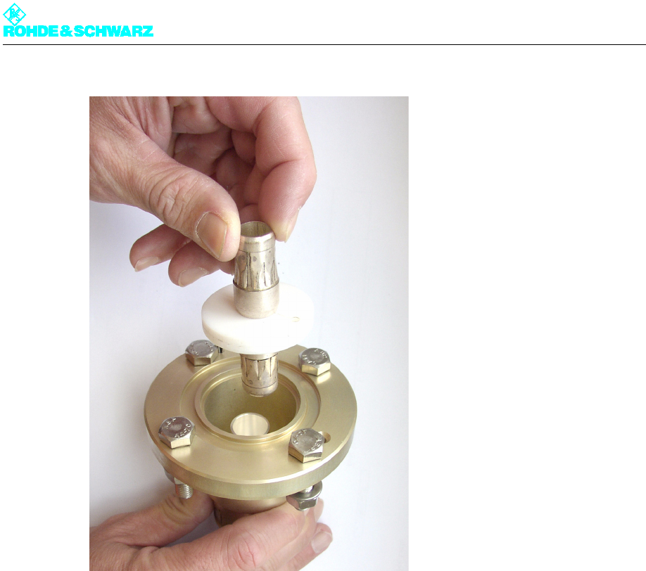
Fig. 14 RF connector with coupling
8.2 Connection of Dummy Antenna
Connect the dummy antenna only for maintenance and repair purposes.
With some dummy antennas that have coolant monitoring and excess temperature moni-
toring, the monitoring equipment can be connected to the transmitter. As a temporary in-
stallation (e.g. during switchover), the main protection loop can be used here (X41.1 and
X41.2 in the power distribution).
)Remove the jumpers and connect the monitoring unit.
If you are using an RF patch panel that allows you to switch between the antenna and dum-
my antenna by means of an RF U-link (permanet installation), you should attach the dummy
antenna monitoring unit to the standby protection loop (X41.3 and X41.4 in the power dis-
tribution). For this to be done, the messages of the patch panel must also be sent to the
controller.

Chapter 3 Installation
2099.9595.72 - 3.19 - E-2
9 Connection Panel
The following table lists all the connectors that you may need to assign.
Connector Description
CANBUS X101A CAN bus data connection for additional racks or output stage A
CANBUS X101B CAN bus data connection for additional racks or output stage B
CANBUS X101C CAN bus data connection for external pump in the case of high-power
transmitters
RS232 X232 Serial data connection for external BITBUS interface
ETHERNET Remote LAN connector or system LAN connector, e.g. for N+1
ANTENNA 1 INPUT Antenna connector for receiver module input 1 in the NETCCU® (DTV
only)
ANTENNA 2 INPUT Antenna connector for receiver module input 2 in the NETCCU® (DTV
only)
TS1 / TS2 Transport stream inputs (digital TV)
TS3 / TS4 Additional connectors to TS1 and TS2 in the case of hierarchical cod-
ing
10 MHz REF INPUT Input for 10 MHz reference for synchronizing the output signal
1PPS MONITORING Test output 1PPS (1PPS = 1 pulse per second)
1PPS EXT INPUT Input for 1PPS signal, reference signal for DVB-T in SFN mode T
TS1/2 MONITORING Monitor output for selected TS signal of inputs 1 and 2
TS3/4 MONITORING Monitor output for selected TS signal of inputs 3 and 4