Acrodyne NW8201E DIGITAL TELEVISION BROADCAST TRANSMITTER User Manual 32 NV8202 26 04 06 01 00
Acrodyne Industries, Inc. DIGITAL TELEVISION BROADCAST TRANSMITTER 32 NV8202 26 04 06 01 00
Acrodyne >
Contents
- 1. Users Manual Part 1
- 2. Users Manual Part 2
- 3. Users Manual Part 3
- 4. Users Manual Part 4
- 5. Users Manual Part 5
- 6. Users Manual Part 6
- 7. Users Manual Part 7
- 8. Users Manual Part 8
- 9. Users Manual Part 9
- 10. Users Manual Part 10
- 11. Users Manual Part 11
- 12. USers Manual Part 12
- 13. Users Manual Part 13
- 14. Users Manual Part 14
- 15. Users Manual Part 15
- 16. Users Manual Part 16
- 17. Users Manual Part 17
- 18. Users Manual Part 18
- 19. Users Manual Part 19
- 20. Users Manual Part 20
Users Manual Part 8
Chapter 2 Design and Characteristics
2099.9595.72 - 2.21 - E-2
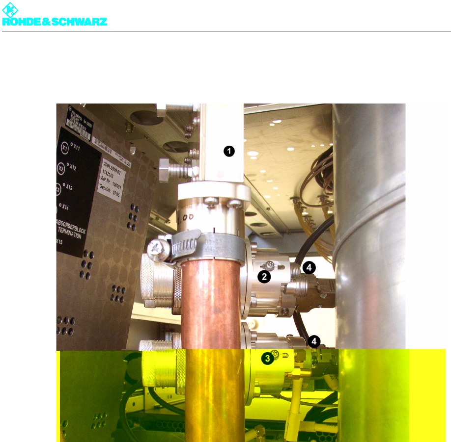
1.6 Test Lightning Protection System
Fig. 25 Equipment in the test lightning protection system
1) Lightning protection
2) Directional coupler N
3) Directional coupler SMA
4) Directional coupler and rectifier unit
The test lightning protection system (lightning protection combined with test points) is locat-
ed at the output of the harmonics filter and contains the following components:
Lightning protection
Directional coupler N
Directional coupler SMA (option ADE only)
Directional coupler and rectifier unit
1.6.1 Lightning Protection
The lightning protection protects the rack from possible damage due to lightning bolts.
Chapter 2 Design and Characteristics
2099.9595.72 - 2.22 - E-2
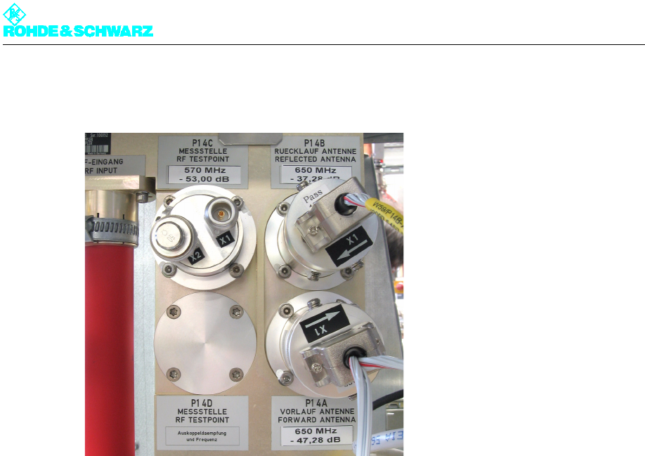
1.6.2 Directional Coupler
Fig. 26 Directional coupler
The forward and reflected power are detected at the transmitter output by means of the fre-
quency-compensated directional couplers P14A (forward) and P14B (reflected). The fre-
quency-compensated directional couplers send a power-proportional DC voltage to the
NETCCU® transmitter control unit via the integrated rectifier circuit. The DC voltages for the
forward and reflected values are displayed in the NETCCU® and also used as an S-mea-
surement for VSWR monitoring (reflection antenna).
Directional coupler P14C is an unassigned test point that can be used either as a forward
or reflected power test point.
The P14D rectifier is used in the digital TV transmitter in connection with option ADE only.
Note The transmitter is switched off because of reflection if the reflected value exceeds 2% of the
forward value after being checked three times.
Chapter 2 Design and Characteristics
2099.9595.72 - 2.23 - E-2
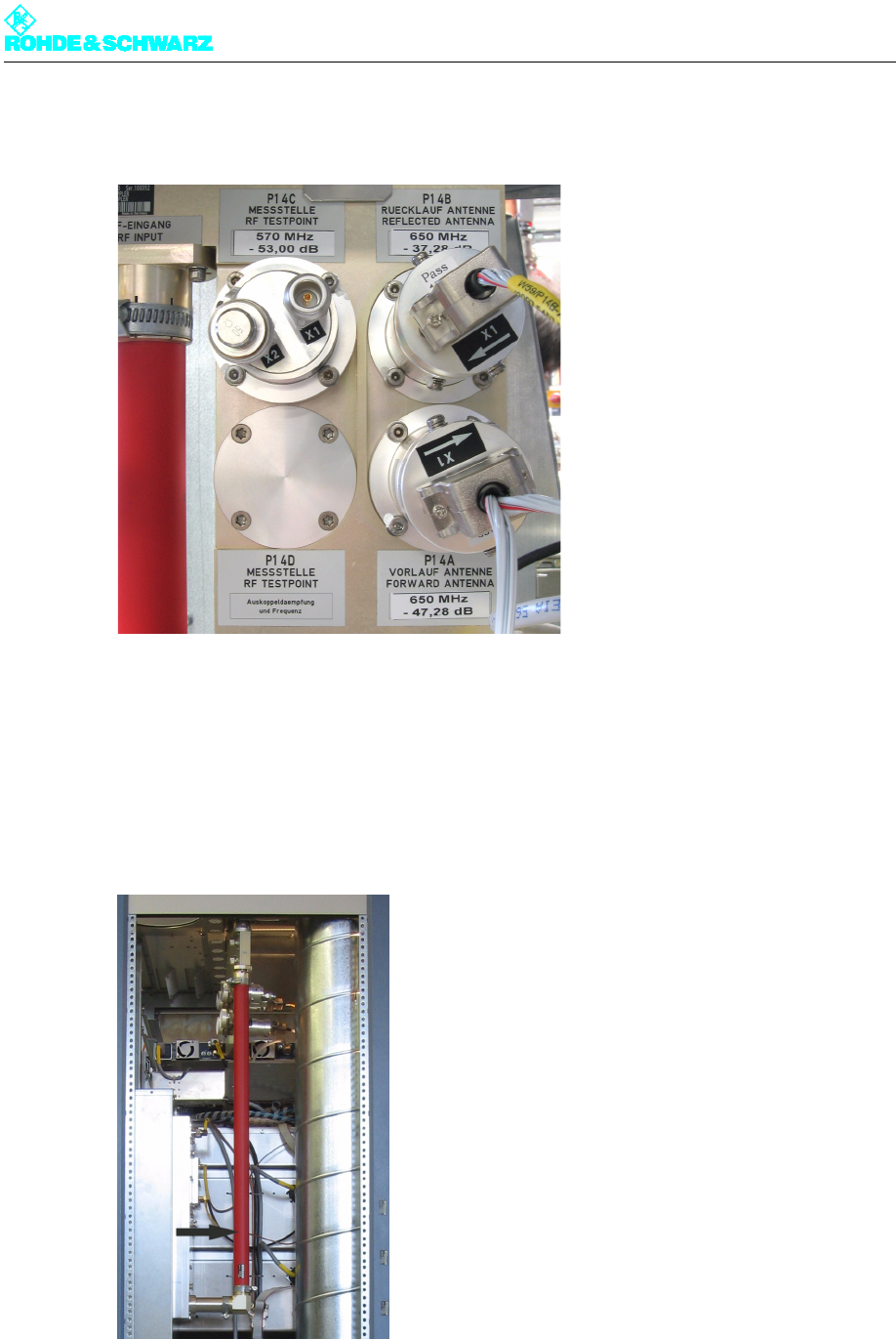
1.6.3 Test Interface
Fig. 27 Test interface
External power measurement equipment can be connected at the unused test interface.
1.7 Harmonics Filter
Fig. 28 Harmonics filter
Chapter 2 Design and Characteristics
2099.9595.72 - 2.24 - E-2
Harmonics filter FM 825 suppresses harmonics. It is set up as a Chebyschev filter of the
11th order using coaxial design for the 13-30 line system. In the signal path, the harmonics
filter is located directly after the combiner.
Note The harmonics filter is lacquered in order to reduce the surface temperature, but high tem-
peratures are nevertheless to be expected.
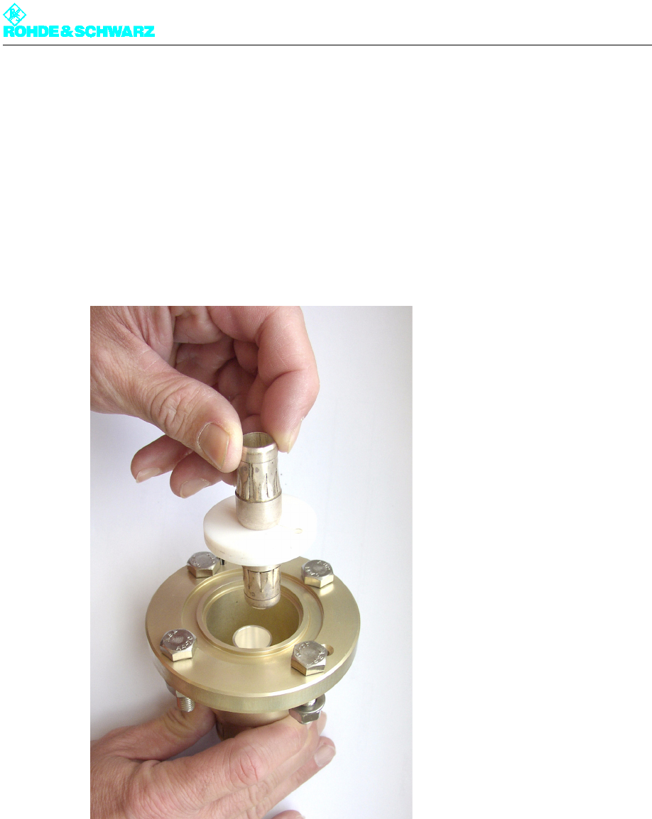
1.8 RF Connector
Fig. 29 RF connector
The RF connector (1 5/8“ EIA flange) is located on the transmitter roof (or under it if pre-
ferred).