Acrodyne NW8201E DIGITAL TELEVISION BROADCAST TRANSMITTER User Manual 32 NV8202 26 04 06 01 00
Acrodyne Industries, Inc. DIGITAL TELEVISION BROADCAST TRANSMITTER 32 NV8202 26 04 06 01 00
Acrodyne >
Contents
- 1. Users Manual Part 1
- 2. Users Manual Part 2
- 3. Users Manual Part 3
- 4. Users Manual Part 4
- 5. Users Manual Part 5
- 6. Users Manual Part 6
- 7. Users Manual Part 7
- 8. Users Manual Part 8
- 9. Users Manual Part 9
- 10. Users Manual Part 10
- 11. Users Manual Part 11
- 12. USers Manual Part 12
- 13. Users Manual Part 13
- 14. Users Manual Part 14
- 15. Users Manual Part 15
- 16. Users Manual Part 16
- 17. Users Manual Part 17
- 18. Users Manual Part 18
- 19. Users Manual Part 19
- 20. Users Manual Part 20
Users Manual Part 2

Broadcasting Division
2095.7346.32 - 2.0 - E-1
CHAPTER 2
DESIGN AND CHARACTERISTICS
Printed in Germany

Chapter 2 Design and Characteristics
2099.9595.72 - 2.01 - E-1
CONTENTS
1 DESIGN AND FUNCTION ................................................................. 1
1.1 Power Distribution ..........................................................................................4
1.1.1 Main Switch (Power Supply Terminal) .........................................................4
1.1.2 Motor Protection Switch ...............................................................................5
1.1.3 Automatic Line Fuse .....................................................................................6
1.1.4 Power Distribution Board ..............................................................................6
1.1.5 Auxiliary Power Supply .................................................................................7
1.1.6 Optional Socket ............................................................................................8
1.1.7 Grounding Bolt .............................................................................................8
1.2 Transmitter Control Unit ................................................................................9
1.2.1 NETCCU ......................................................................................................9
1.2.2 Rack Controller ...........................................................................................10
1.3 Connection Panel .........................................................................................11
1.4 Exciter Unit ....................................................................................................12
1.4.1 Exciter ........................................................................................................13
1.4.2 Exciter Switch .............................................................................................13
1.5 Output Stage Unit .........................................................................................14
1.5.1 Splitter ........................................................................................................16
1.5.2 Amplifier .....................................................................................................17
1.5.3 Combiner ....................................................................................................18
1.5.4 Absorber .....................................................................................................19
1.6 Test Lightning Protection System ..............................................................20
1.6.1 Lightning Protection ....................................................................................20
1.6.2 Directional Coupler .....................................................................................21
1.6.3 Test Interface .............................................................................................22
1.7 Harmonics Filter ...........................................................................................22
1.8 RF Connector ................................................................................................23
1.9 Cooling system .............................................................................................24
1.9.1 Air Intake/Exhaust Duct ..............................................................................25
1.9.2 Fans ...........................................................................................................26
1.9.3 Starting Capacitor .......................................................................................27
1.9.4 Differential Pressure Gage .........................................................................28
1.9.5 Temperature Sensors .................................................................................29

Chapter 2 Design and Characteristics
2099.9595.72 - 2.02 - E-1
1.10 Transformer ..................................................................................................30
2 SPECIFICATIONS ........................................................................... 31
2.1 Transmitter System in General ...................................................................31
2.2 Transmitter System - Specifically NW8202 .................................................31
Chapter 2 Design and Characteristics
2099.9595.72 - 2.1 - E-2
1 Design and Function
The new, air-cooled Transmitter Family NW820x is designed for transmitting digital TV sig-
nals in the IV and V frequency bands (UHF). The digital standards DVB-T, ATSC, DMB-T
and MediaFLO can be transmitted.
LDMOS transistor-based amplifiers ensure high output power while requiring only minimum
space. For digital TV, output power of 325 W to 1.95 kW is available.
Both the power class of the transmitter and its type designation depend on the number of
built-in amplifiers.
This chapter describes the transmitter's design and the functions of its components.
Name Number of amplifiers Power
NW8201 1 325 W
NW8202 2 650 W
NW8203 3 975 W
NW8204 4 1.3 kW
NW8205 5 1.625 kW
NW8206 6 1.95 kW
Chapter 2 Design and Characteristics
2099.9595.72 - 2.2 - E-2
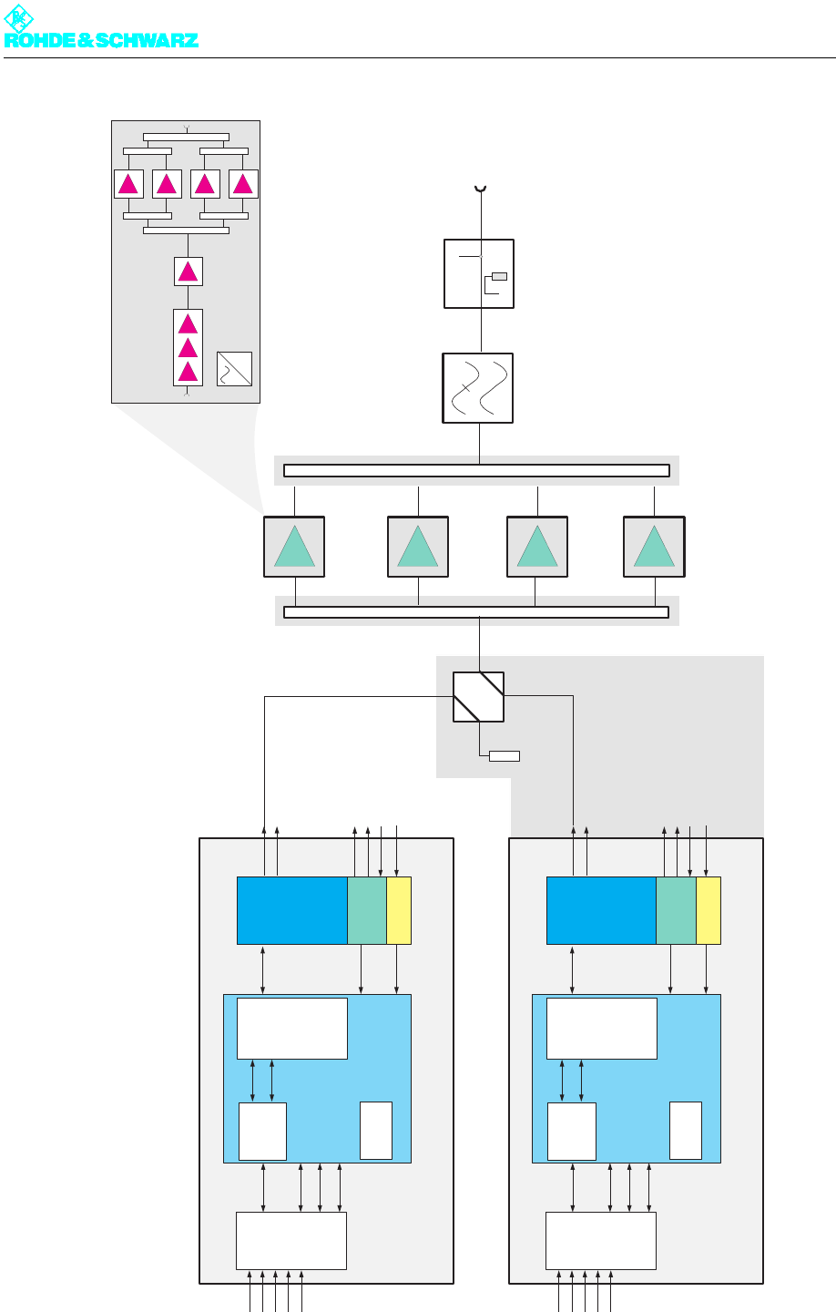
Fig. 1 Block diagram of DTV transmitters: In this example NW8204E/V
Exciter Standby
Amplifier
VM8350A1
=
Lightning
Protection
Measurement
Coupler
Harmonics
Filter
RF
Output
max. 6 VM8350A1
Input
Interface
DTV
TS1
TS2
TS3
TS4
Ext 1PPS
Coder
I
Q
Linear
and
nonlinear
Precorrection
Upconverter
Dig. IQ
Dig. IF
120MHz
Synthesizer
Down-
converter
PLL
Mainboard
LO Mon.
Ext. REF
10MHz Mon.
RF N
RF DTV
RF Mon.
TV Exciter SX800 A
3xTS
120MHz
Control
1pps
Input
Interface
DTV
TS1
TS2
TS3
TS4
Ext 1PPS
Coder
I
Q
Linear
and
nonlinear
Precorrection
Upconverter
Dig. IQ
Dig. IF
120MHz
Synthesizer
Down-
converter
PLL
Mainboard
LO Mon.
Ext. REF
10MHz Mon.
RF N
RF DTV
RF Mon.
TV Exciter SX800 B
3xTS
120MHz
Control
1pps
Option
Chapter 2 Design and Characteristics
2099.9595.72 - 2.3 - E-2
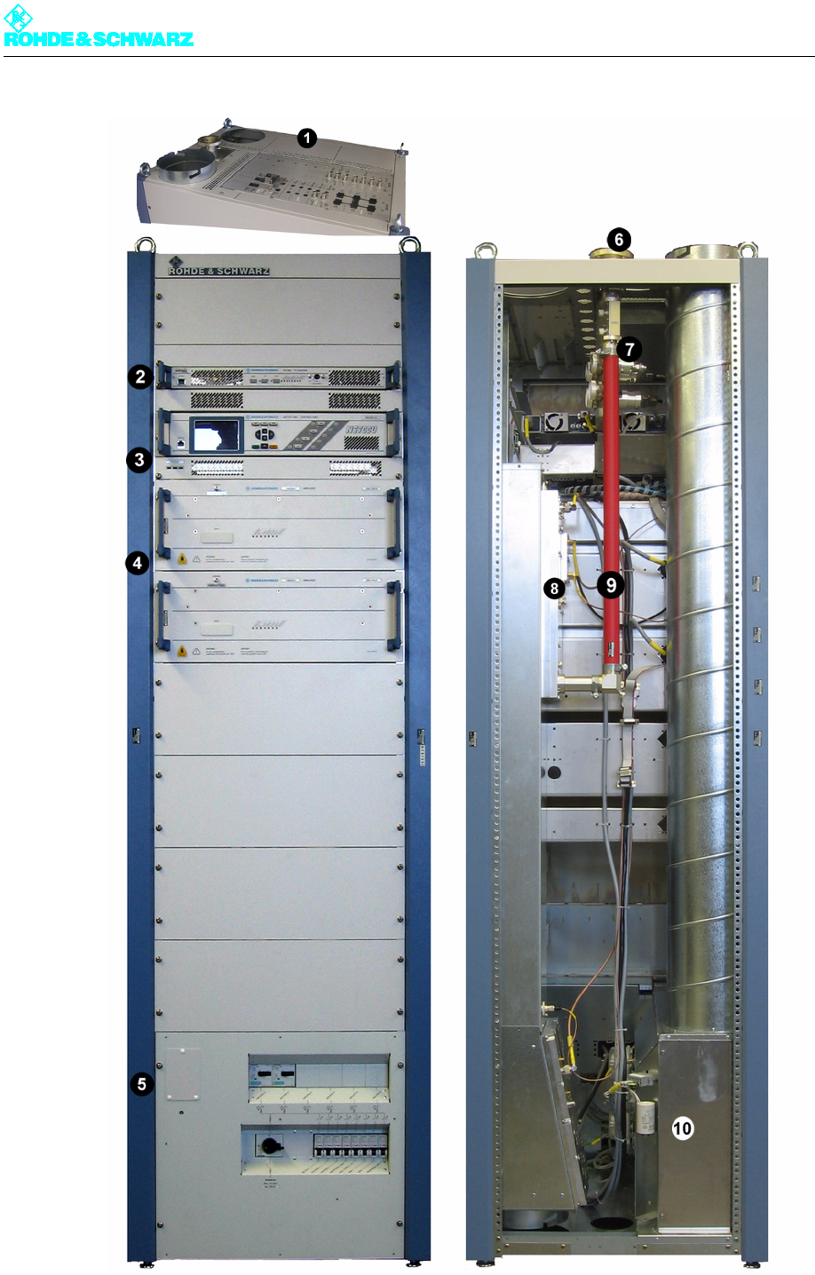
Fig. 2 Transmitter NW8202 modules

Chapter 2 Design and Characteristics
2099.9595.72 - 2.4 - E-2
1) Connection panel
2) Exciter
3) Transmitter control unit
4) Output stage
5) Power distribution
6) RF connector
7) Test lightning protection system
8) Splitter/combiner unit
9) Harmonics filter
10) Intake box (fan)
The NW8202 consists of the following units and modules:
Power distribution
– Main switch
– Motor protection switch
– Automatic line fuse
– Power distribution board
– Auxiliary power supply
– Optional socket
– Grounding bolt
Transmitter control unit components
–NETCCU
®
– Rack controller
Connection panel
Exciter unit
– Exciters (1 or 2)
– Exciter switch (in case of standby exciter)
Output stage unit
– Splitter
– Amplifiers (1 to 6)
– Combiner
– Absorber
Harmonics filter
Test lightning protection system
– Lightning protection
– Directional coupler
–Test interface
RF Connector
Cooling system
– Air intake and exhaust duct
–Fans (2)
– Starting capacitor (2)
– Differential pressure gages (2)
– Temperature sensors (2)
Transformer (optional)
Chapter 2 Design and Characteristics
2099.9595.72 - 2.5 - E-2
1.1 Power Distribution
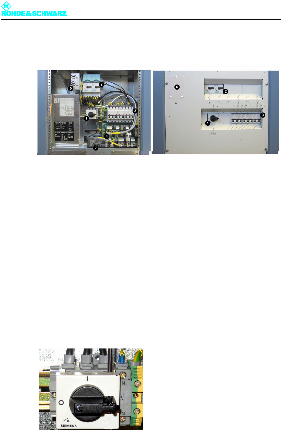
Fig. 3 Power distribution
1) Main switch (power supply terminal)
2) Motor protection switch
3) Automatic line fuse
4) Power distribution board
5) Auxiliary power supply
6) Optional socket
7) Grounding bolt
The power distribution is designed for max. 32 A and contains the following components:
Main switch (power supply terminal)
Motor protection switch
Automatic line fuse
Power distribution board
Auxiliary power supply
Optional socket
Grounding Bolt
1.1.1 Main Switch (Power Supply Terminal)
Fig. 4 Main switch
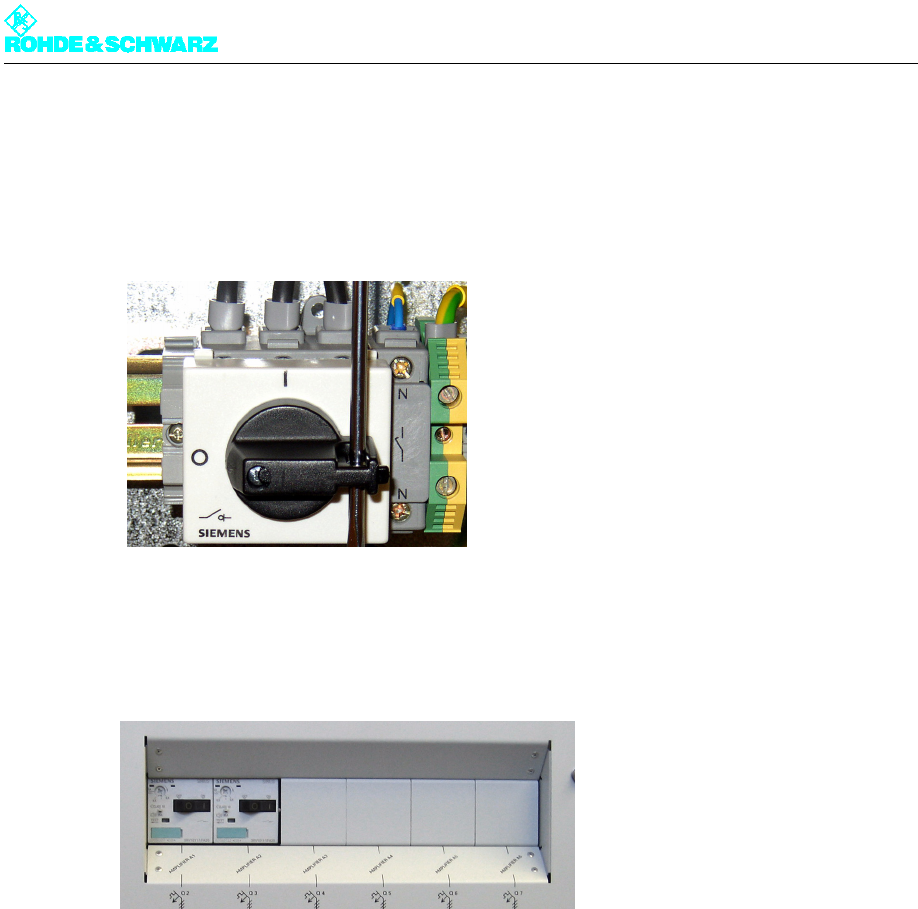
Chapter 2 Design and Characteristics
2099.9595.72 - 2.6 - E-2
The main switch fully disconnects the transmitter rack from the AC power supply. It is con-
nected to three-phase alternating current and a neutral conductor.
Note The main switch can be equipped with a padlock to prevent unauthorized persons from
switching it off and on.
Fig. 5 Main switch with fuse
1.1.2 Motor Protection Switch
Fig. 6 Motor protection switches
The motor protection switches are used to switch amplifiers on and off, as well as to protect
the subsequent supply cables and amplifiers from overloading. As shipped from the factory,
the number of motor protection switches matches the number of built-in amplifiers. The
arrangement of amplifiers and motor protection switches is shown on the front panel.
The thermally activated overcurrent release of the motor protection switches is factory-set.
Chapter 2 Design and Characteristics
2099.9595.72 - 2.7 - E-2
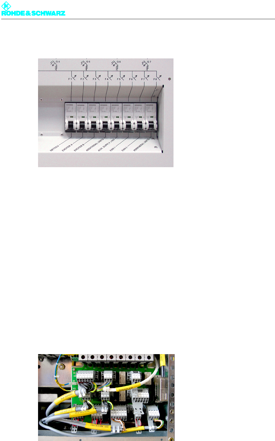
1.1.3 Automatic Line Fuse
Fig. 7 Automatic line fuses
The automatic line fuses are used to protect the power lines, e.g. in the event of a short-
circuit and when the following equipment is switched on and off:
NetCCU® (F1)
EXCITER A/B (F2/F3)
Optional add-on equipment (F4)
Auxiliary power supply (F5)
Fan (F6/F7)
Controller (F8)
– External cooling system
– Controller for dummy antennas
– Optional external fan
The arrangement of the equipment and the automatic line fuses is shown on the cover.
1.1.4 Power Distribution Board
Fig. 8 Power distribution board

Chapter 2 Design and Characteristics
2099.9595.72 - 2.8 - E-2
The power distribution board is directly connected to the overcurrent protector switches and
contains permanently-wired transmitter-internal cables and transmitter-external compo-
nents (customer-interfaces) to which external equipment can be connected.
Note The appropriate unequipped connectors are part of the transmitter and are located at the
assigned positions.
The following equipment is or can be connected to the power distribution board:
NETCCU®
EXCITER A/B
Fan
External fan (switched phase for controlling an external contactor)
External dummy antenna (switched phase for controlling an external contactor)
RF carrier loop
External RF absorber fault (system absorber)
Overcurrent (external cooling)
Connector for rack controller
1.1.5 Auxiliary Power Supply
Fig. 9 Auxiliary power supply
The primary task of the auxiliary power supply (+12 V) is to provide power to the additional
control components in the rack. The required redundancy of this auxiliary voltage is gener-
ated via the exciters, which also output a +12 V current.
The following modules are powered by the auxiliary power supply:
Rack controller
CANBUS interface of the amplifiers
Switching relay in the power distribution
RF rectifier/test directional coupler when the standby transmitter is active