Acrodyne NW8201E DIGITAL TELEVISION BROADCAST TRANSMITTER User Manual 32 NV8202 26 04 06 01 00
Acrodyne Industries, Inc. DIGITAL TELEVISION BROADCAST TRANSMITTER 32 NV8202 26 04 06 01 00
Acrodyne >
Contents
- 1. Users Manual Part 1
- 2. Users Manual Part 2
- 3. Users Manual Part 3
- 4. Users Manual Part 4
- 5. Users Manual Part 5
- 6. Users Manual Part 6
- 7. Users Manual Part 7
- 8. Users Manual Part 8
- 9. Users Manual Part 9
- 10. Users Manual Part 10
- 11. Users Manual Part 11
- 12. USers Manual Part 12
- 13. Users Manual Part 13
- 14. Users Manual Part 14
- 15. Users Manual Part 15
- 16. Users Manual Part 16
- 17. Users Manual Part 17
- 18. Users Manual Part 18
- 19. Users Manual Part 19
- 20. Users Manual Part 20
Users Manual Part 18

Chapter 8 Service
2099.9595.72 - 8.19 - E-2
6 Exciter Components
You can replace the following exciter components:
Exciter
Exciter Switch
6.1 Replacing the Exciter
6.1.1 Removing the Exciter
1. Switch off automatic line fuse F2 (Exciter A) or F3 (Exciter B).
2. Undo the two captive screws (Torx screwdriver No. 20) of both the NETCCU® and the
exciter on the front brackets (next to the handles).
3. Using the handles, slowly pull out the rackmount from the rack as far as it will go (the
guide rails will engage and lock in place).
4. Disconnect the control cable from the side of the exciter switch.
5. Disconnect the cabling from the upper and lower side of the exciter switch.
ATTENTION!
Always make sure that the power supply is disconnected before commencing any service
work on the transmitter rack; this will prevent injury caused by electric shock and damage
to the instruments.
Chapter 8 Service
2099.9595.72 - 8.20 - E-2
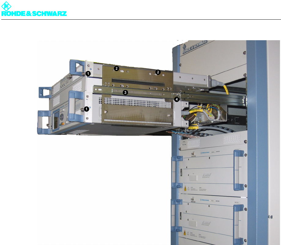
Fig. 14 Removing the exciter from the transmitter rack
1) Captive screws on the front panel of the built-in equipment (in this case exciter and NETCCU)
2) Screw-connections of the exciter on the rackmount
3) Guide rails
4) Safety lever for undoing the latch of the guide rails
6. On both sides of the exciter undo the two fixing screws (Torx screwdriver No. 9) from the
rackmount.
7. Pull the exciter from the rackmount.
6.1.2 Installing the Exciter
To install the unit in the transmitter, reverse the procedure used to remove it.
1. Slide the exciter into the cabinet horizontally on the support brackets until the screw
holes on the cabinet and on the side panels of the exciter match.
2. Fasten the exciter with two screws on each side.
3. Connect the cables to the exciter according to the labeling (see yellow cable collars).
4. Undo the latch on the guide rails. Simultaneously press down the safety lever on the
right side and up on the left side and insert the rackmount into the rack.
5. Refasten the captive screws to the front panels of the NETCCU® and the exciter.
Chapter 8 Service
2099.9595.72 - 8.21 - E-2
6.2 Replacing the Exciter Switch
6.2.1 Removing the Exciter Switch
The exciter switch is included in transmitters with the standby exciter option (two exciters);
it is located behind the two exciters.
Note So that you can conveniently remove the exciter switch, you need to retract the NETCCU®
and the exciter from the rack.
1. Undo the two captive screws of both the NETCCU® and the exciter on the front brackets
(next to the handles).
2. Using the handles, slowly pull out the rackmount from the rack as far as it will go (the
guide rails will engage and lock in place).
3. Disconnect power cables from the side of the exciter switch.
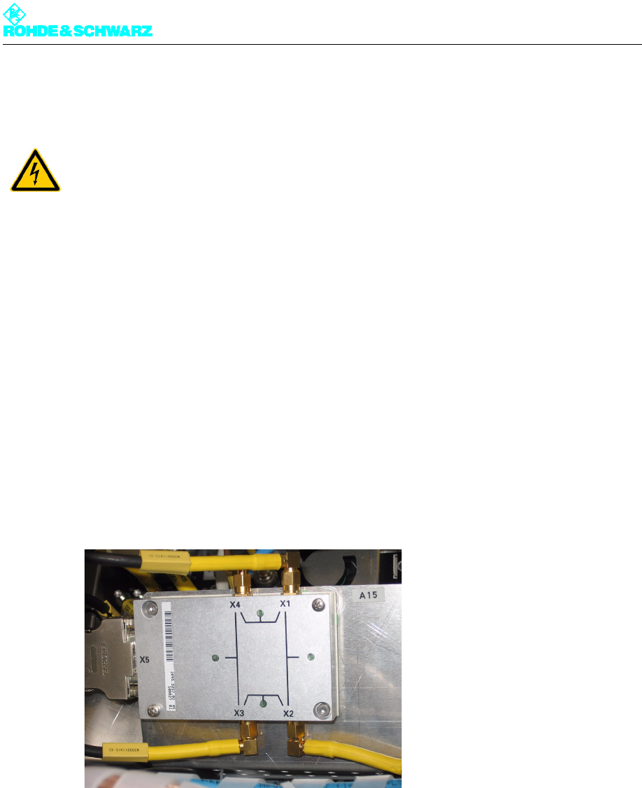
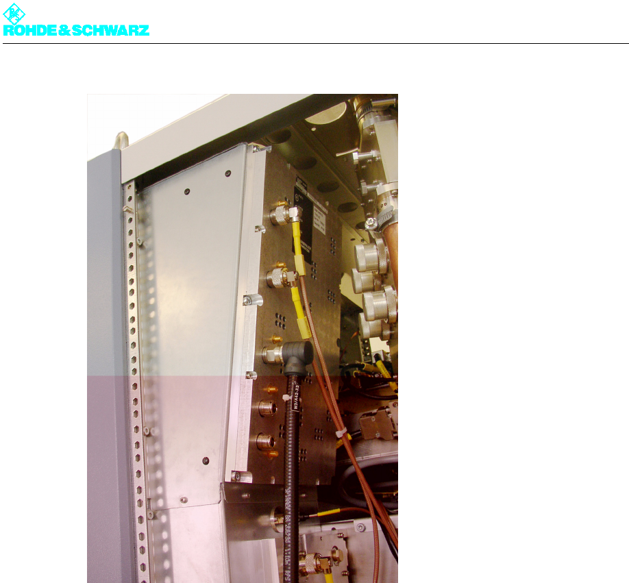
Fig. 15 Removing the exciter switch from the transmitter rack
4. Disconnect all cabling from the rear of the exciter switch.
5. Undo the fixing screws on the exciter switch.
6. Pull the exciter switch from the transmitter rack.
6.2.2 Installing the Exciter Switch
To install the unit in the transmitter, reverse the procedure used to remove it.
ATTENTION!
Always make sure that the power supply is disconnected before commencing any service
work on the transmitter rack; this will prevent injury caused by electric shock and damage
to the instruments.

Chapter 8 Service
2099.9595.72 - 8.22 - E-2
1. Connect the cables to the exciter switch according to the labeling (see yellow cable col-
lars).
2. Undo the latch on the guide rails. Simultaneously press down the safety lever on the
right side and up on the left side and insert the rackmount into the rack.
3. Refasten the captive screws to the front panels of the NETCCU® and the exciter.
Chapter 8 Service
2099.9595.72 - 8.23 - E-2
7 Output Stage Components
You can replace the following output stage components:
Amplifier
Absorber
Note Because of the extremely small probability of failure, replacement of the splitter-combiner
unit will not be described.
7.1 Replacing the Amplifier
When replacing an amplifier from the Rohde & Schwarz NW8000 transmitters, you do not
have to remove any of the lines since the connections on the rear panel of the device are
connected to the rack using automatic connectors.
7.1.1 Removing the Amplifier
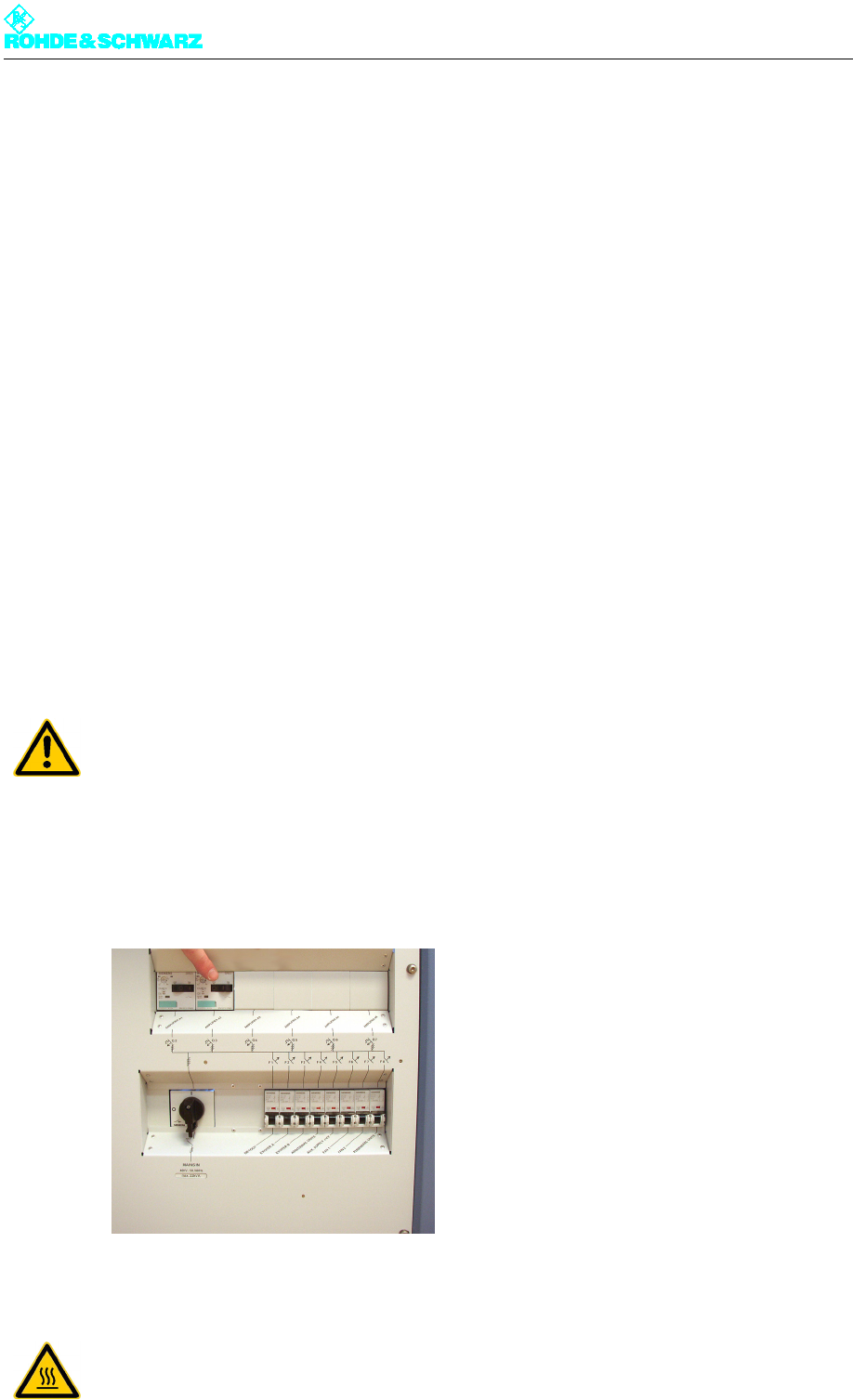
1. Switch off the amplifier via the AC distributor in the transmitter rack (turn the the appro-
priate protective switch to the "OFF" position).
Note The other devices in the transmitter rack can remain connected. A transmitter with mul-
tiple amplifiers can remain in operation with reduced power during the exchange of the
amplifier.
2. Undo the four captive screws (Torx screwdriver No. 20) on each side of the front panel.
ATTENTION!
Prior to being removed, the amplifier must be switched free of all voltages in order to pre-
vent any possible damage to the device due to contact consumption.
CAUTION!
Risk of burns on the heat sink. Let the amplifier cool down for about five minutes with the
transmitter cooling switched on before you remove it from the transmitter rack.
Chapter 8 Service
2099.9595.72 - 8.24 - E-2
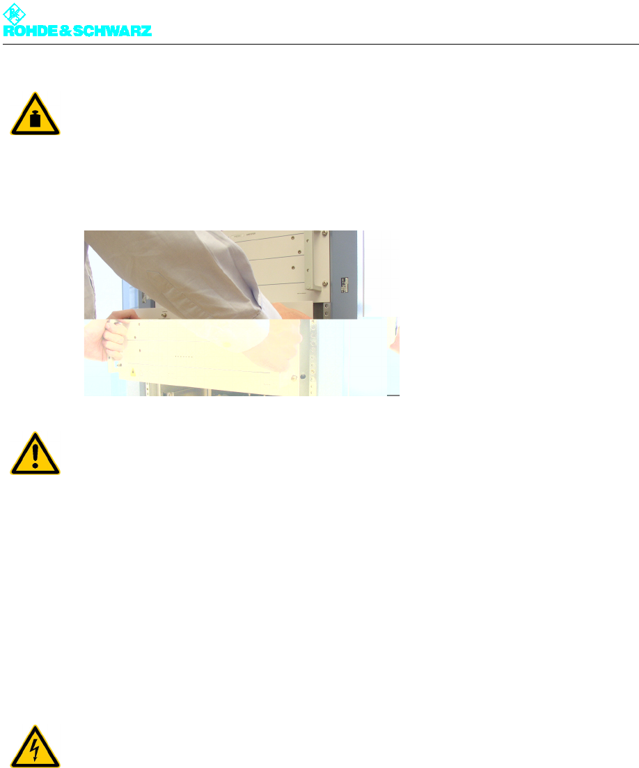
3. Slowly pull the amplifier from the rack using the handles.
The automatic connectors should release on the rear panel of the device.
4. Put the amplifier down with the bottom of the instrument facing downward.
7.1.2 Installing the Amplifier
To install the unit in the transmitter, reverse the procedure used to remove it.
7.2 Replacing the Absorber
7.2.1 Removing the Absorber
To remove the absorber proceed as follows:
1. Using a Torx screwdriver No. 20, remove the rear panel of the rack.
2. Disconnect the RF connecting cables W1, W2 and W3 to the splitter-combiner unit.
3. Using a Torx screwdriver No. 20 remove all six fixing screws.
4. Pull the absorber unit from the rackmount air outlet duct.
CAUTION!
When you pull it out of the transmitter rack, do not allow the amplifier to fall. Support it from
below. The amplifier weighs about 25 kg so we suggest that you use two people to handle
it.
ATTENTION!
To avoid damaging the connectors, do not place the amplifier on its back.
ATTENTION!
Always make sure that the power supply is disconnected before commencing any service
work on the transmitter rack; this will prevent injury caused by electric shock and damage
to the instruments.
Chapter 8 Service
2099.9595.72 - 8.25 - E-2
Fig. 16 Removing the absorber
7.2.2 Installing the Absorber
To install the unit in the transmitter, reverse the procedure used to remove it.