Acrodyne NW8201E DIGITAL TELEVISION BROADCAST TRANSMITTER User Manual 32 NV8202 26 04 06 01 00
Acrodyne Industries, Inc. DIGITAL TELEVISION BROADCAST TRANSMITTER 32 NV8202 26 04 06 01 00
Acrodyne >
Contents
- 1. Users Manual Part 1
- 2. Users Manual Part 2
- 3. Users Manual Part 3
- 4. Users Manual Part 4
- 5. Users Manual Part 5
- 6. Users Manual Part 6
- 7. Users Manual Part 7
- 8. Users Manual Part 8
- 9. Users Manual Part 9
- 10. Users Manual Part 10
- 11. Users Manual Part 11
- 12. USers Manual Part 12
- 13. Users Manual Part 13
- 14. Users Manual Part 14
- 15. Users Manual Part 15
- 16. Users Manual Part 16
- 17. Users Manual Part 17
- 18. Users Manual Part 18
- 19. Users Manual Part 19
- 20. Users Manual Part 20
Users Manual Part 14

Broadcasting Division
2095.7346.32 - 6.0 - E-1
CHAPTER 6
MAINTENANCE
Printed in Germany

Chapter 6 Maintenance
2098.1190.72 - 6.01 - E-1
CONTENTS
1 Maintenance Information ................................................................ 1
1.1 Recommendation ...........................................................................................1
1.2 Maintenance of Subcontractor Products .....................................................1

Chapter 6 Maintenance
2098.1190.72 - 6.1 - E-1
1 Maintenance Information
1.1 Recommendation
The transmitter is designed to provide years of operation with little maintenance. Rohde &
Schwarz recommends to perform the following maintenance tasks as a precaution:
Software updates for the NETCCU®, the exciter and the amplifier, if required
(for improved performance and for retrofitting options)
Replacing the two rack fans after approx. 40000 operating hours
Replacing the two fans in the exciter after approx. 40000 operating hours
1.2 Maintenance of Subcontractor Products
Subcontractor products such as external air filters must be maintained in accordance with
the maintenance instructions of the individual manufacturer/product.

Broadcasting Division
2095.7346.32 - 7.0 - E-1
CHAPTER 7
TROUBLESHOOTING
Printed in Germany

Chapter 7 Troubleshooting
2098.1190.72 - 7.01 - E-1
CONTENTS
1 Information ....................................................................................... 1

Chapter 7 Troubleshooting
2098.1190.72 - 7.1 - E-1
1 Information
Troubleshooting information will be provided at a later date.

Broadcasting Division
2095.7346.32 - 8.0 - E-1
CHAPTER 8
SERVICE
Printed in Germany

Chapter 8 Service
2099.9595.72 - 8.01 - E-2
CONTENTS
1 Required Test Equipment and Tools ............................................. 1
2 Overview ........................................................................................... 2
3 Preparatory Work ............................................................................. 3
3.1 Safety ...............................................................................................................3
3.2 Rack Cabling ...................................................................................................3
3.3 Removing the Front Panel/Rear Panel .........................................................4
4 Power Distribution ........................................................................... 5
4.1 Replacing the Main Switch ............................................................................5
4.1.1 Removing the Main Switch ...........................................................................5
4.1.2 Installing the Main Switch .............................................................................6
4.2 Replacing the Motor Protection Switch ........................................................7
4.2.1 Removing the Motor Protection Switch ........................................................7
4.2.2 Installing the Motor Protection Switch ..........................................................9
4.3 Replacing the Power Distribution Board ....................................................10
4.3.1 Removing the Power Distribution Board ....................................................10
4.3.2 Installing the Power Distribution Board ......................................................11
4.4 Replacing an Automatic Line Fuse .............................................................12
4.4.1 Removing an Automatic Line Fuse ............................................................12
4.4.2 Installing an Automatic Line Fuse ..............................................................13
4.5 Replacing the Auxiliary Power Supply .......................................................13
4.5.1 Removing the Auxiliary Power Supply .......................................................13
4.5.2 Installing the Auxiliary Power Supply .........................................................14
5 Transmitter Control Unit ............................................................... 15
5.1 Replacing the NETCCU ................................................................................15
5.1.1 Removing the NETCCU .............................................................................15
5.1.2 Preparing the NETCCU for Installation ......................................................16
5.1.3 Installing the NETCCU ...............................................................................17
5.2 Replacing the Rack Controller ....................................................................17
5.2.1 Removing the Rack Controller ...................................................................17
5.2.2 Installing the Rack Controller .....................................................................18

Chapter 8 Service
2099.9595.72 - 8.02 - E-2
6 Exciter Components ...................................................................... 19
6.1 Replacing the Exciter ...................................................................................19
6.1.1 Removing the Exciter .................................................................................19
6.1.2 Installing the Exciter ...................................................................................20
6.2 Replacing the Exciter Switch ......................................................................21
6.2.1 Removing the Exciter Switch ......................................................................21
6.2.2 Installing the Exciter Switch ........................................................................21
7 Output Stage Components ........................................................... 23
7.1 Replacing the Amplifier ...............................................................................23
7.1.1 Removing the Amplifier ..............................................................................23
7.1.2 Installing the Amplifier ................................................................................24
7.2 Replacing the Absorber ...............................................................................24
7.2.1 Removing the Absorber ..............................................................................24
7.2.2 Installing the Absorber ................................................................................25
8 Harmonics Filter ............................................................................ 26
8.1 Replacing the Harmonics Filter ...................................................................26
8.1.1 Removing the Harmonics Filter ..................................................................26
8.1.2 Installing the Harmonics Filter ....................................................................27
9 Cooling System .............................................................................. 28
9.1 Replacing the Fan .........................................................................................28
9.1.1 Removing the Fan ......................................................................................28
9.1.2 Installing the Fan ........................................................................................30
9.2 Replacing the Starting Capacitor ................................................................30
9.2.1 Removing the Starting Capacitor ...............................................................30
9.2.2 Installing the Starting Capacitor .................................................................31
9.3 Replacing the Differential Pressure Gage ..................................................31
9.3.1 Removing the Differential Pressure Gage ..................................................32
9.3.2 Installing the Differential Pressure Gage ....................................................32
9.4 Replacing Temperature Sensors ................................................................33
9.4.1 Removing a Temperature Sensor ..............................................................33
9.4.2 Installing a Temperature Sensor ................................................................34
10 Transformer .................................................................................... 35

Chapter 8 Service
2099.9595.72 - 8.1 - E-2
1 Required Test Equipment and Tools
The specified tools and test equipment include only those items needed for removing sys-
tem components and carrying out simple checks on them.
Depending on the service work to be performed, you will require the following tools:
Screwdriver No. 0
Screwdriver No. 1
Screwdriver No. 2
Phillips screwdriver No. 0
Phillips screwdriver No. 1
Phillips screwdriver No. 2
Torx screwdriver No. 8
Torx screwdriver No. 9
Torx screwdriver No. 20
Hexagonal socket No. 3
Hexagonal socket No. 6
Open-end wrench No. 7
Open-end wrench No. 8
Open-end wrench No. 13
Multimeter

Chapter 8 Service
2099.9595.72 - 8.2 - E-2
2 Overview
You can remove and exchange the following instruments and transmitter components if er-
rors occur:
Power distribution
– Main switch
– Motor protection switch
– Automatic line fuse
– Power distribution board
– Auxiliary power supply
Transmitter control unit
–NETCCU
®
– Rack controller
Exciter components
–Exciter
– Exciter switch (in the case of exciter standby)
Output stage components
– Amplifiers
– Absorber
Harmonics filter
Cooling system
–Fans
– Starting capacitor
– Differential pressure gage
– Temperature sensors
Transformer (optional)
Chapter 8 Service
2099.9595.72 - 8.3 - E-2
3 Preparatory Work
3.1 Safety
Note Full information on the subject of safety can be found in the section "Safety".
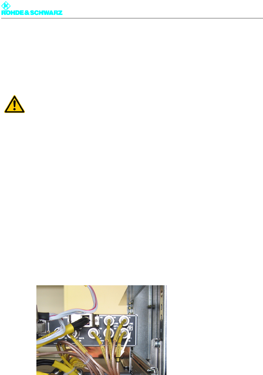
3.2 Rack Cabling
The standard components of the NW820x transmitter are fully cabled together on delivery.
You need to reconnect the separate replacement instruments during service work.
Each cable has a yellow collar at each end, inscribed with the cable number (W...) and the
intended purpose (module number A..., connector number X...). This makes it easier to
connect the cable concerned to the intended slot or connection point, since the modules
are provided with an engraved or self-adhesive circuit diagram.
For easy connection of replacement instruments or devices proceed as follows:
1. Find the plug (connector) number from the yellow collar on the cable.
2. Find the same number on the instrument you wish to connect (by looking for the female
connector or circuit diagram).
3. Insert the plug connector into the corresponding female connector.
ATTENTION!
You need to pay particular attention to safety during service work. As a matter of principle
all service work must be carried out by qualified personnel on components that are free of
any voltage. Heavy components such as amplifiers must always be replaced in twos.
Chapter 8 Service
2099.9595.72 - 8.4 - E-2
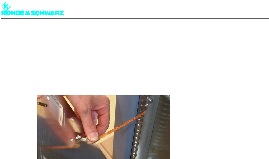
3.3 Removing the Front Panel/Rear Panel
To remove the front panel/rear panel proceed as follows:
)Using a Torx screwdriver, remove the front or rear panel.
Fig. 1 Ground terminal of a front panel/rear panel