Acrodyne NW8201E DIGITAL TELEVISION BROADCAST TRANSMITTER User Manual 32 NV8202 26 04 06 01 00
Acrodyne Industries, Inc. DIGITAL TELEVISION BROADCAST TRANSMITTER 32 NV8202 26 04 06 01 00
Acrodyne >
Contents
- 1. Users Manual Part 1
- 2. Users Manual Part 2
- 3. Users Manual Part 3
- 4. Users Manual Part 4
- 5. Users Manual Part 5
- 6. Users Manual Part 6
- 7. Users Manual Part 7
- 8. Users Manual Part 8
- 9. Users Manual Part 9
- 10. Users Manual Part 10
- 11. Users Manual Part 11
- 12. USers Manual Part 12
- 13. Users Manual Part 13
- 14. Users Manual Part 14
- 15. Users Manual Part 15
- 16. Users Manual Part 16
- 17. Users Manual Part 17
- 18. Users Manual Part 18
- 19. Users Manual Part 19
- 20. Users Manual Part 20
Users Manual Part 16
Chapter 8 Service
2099.9595.72 - 8.10 - E-2
1) Room for the shorting plug pins
4.3 Replacing the Power Distribution Board
4.3.1 Removing the Power Distribution Board
To remove the power distribution board proceed as follows:
1. Using a Torx screwdriver No. 20, remove the front panel of the power distribution.
2. Remove all plugs before removing the power distribution board.
3. Unscrew the SUB-D connector on the right of the longitudinal edge (two screws).
4. Use a Phillips screwdriver No. 1 to undo eight screws on the automatic line fuses.
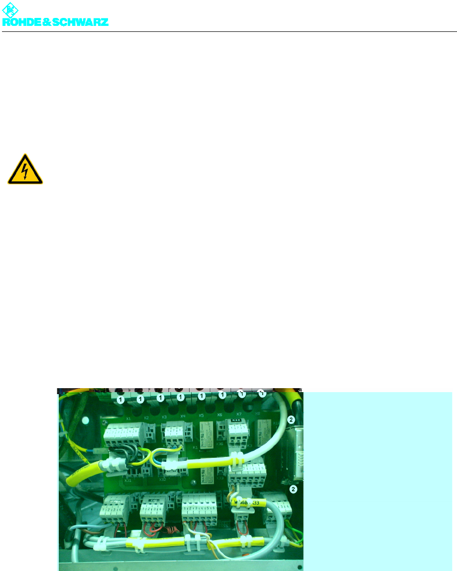
Fig. 7 Removing the power distribution board
1) Screws on the automatic line fuses
2) Screws on the SUB-D connector
5. Using a Torx screwdriver No. 8 remove seven fixing screws from the power distribution
board.
ATTENTION!
Always make sure that the power supply is disconnected before commencing any service
work on the transmitter rack; this will prevent injury caused by electric shock and damage
to the instruments.
Chapter 8 Service
2099.9595.72 - 8.11 - E-2
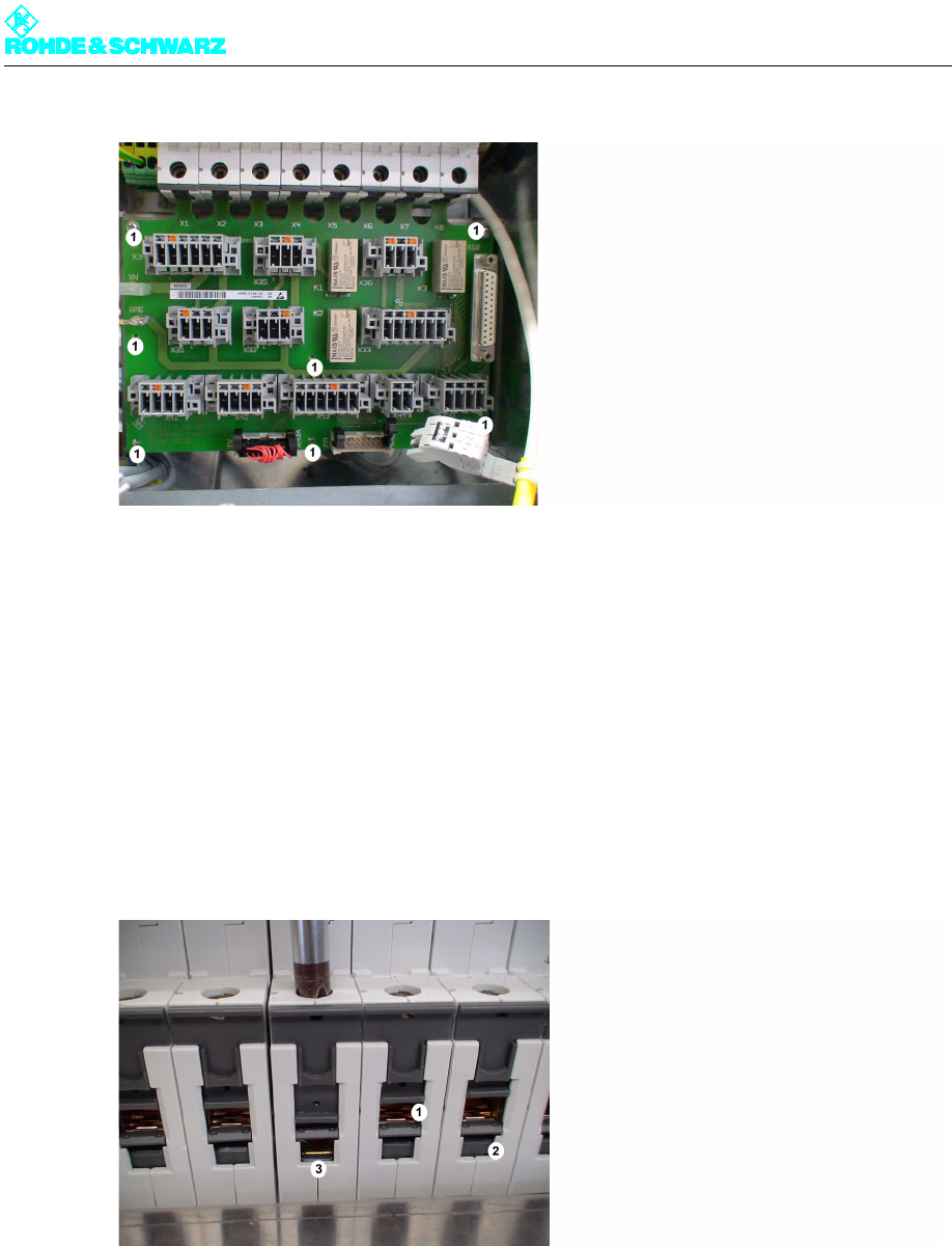
Fig. 8 Removing the power distribution board
1) Fixing screws on the power distribution board
6. To take out the PCB, first slide it downward.
4.3.2 Installing the Power Distribution Board
)Replace the power distribution board by proceeding in the reverse order.
Note When replacing the power distribution board, make sure that it feeds into the right slots.
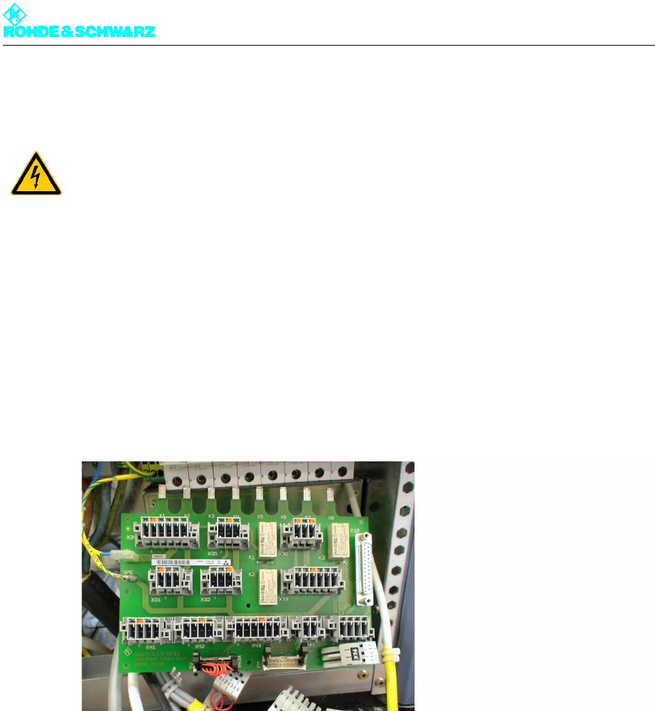
Fig. 9 Installing the power distribution board
1) Wrong
2) Right
3) Pressing with a screwdriver visibly opens the right chamber
Chapter 8 Service
2099.9595.72 - 8.12 - E-2
4.4 Replacing an Automatic Line Fuse
4.4.1 Removing an Automatic Line Fuse
Note Before removing an automatic line fuse, the power distribution board must be removed (see
"Removing the Power Distribution Board").
To remove the automatic line fuse proceed as follows:
1. Remove the power distribution board.
2. From above, grip the back of the automatic line fuse you wish to remove and undo the
white plastic springs.
3. Remove the automatic line fuse.
ATTENTION!
Always make sure that the power supply is disconnected before commencing any service
work on the transmitter rack; this will prevent injury caused by electric shock and damage
to the instruments.

Chapter 8 Service
2099.9595.72 - 8.13 - E-2
Fig. 10 Automatic line fuse
1) Upper plastic spring
2) Lower plastic spring
Chapter 8 Service
2099.9595.72 - 8.14 - E-2
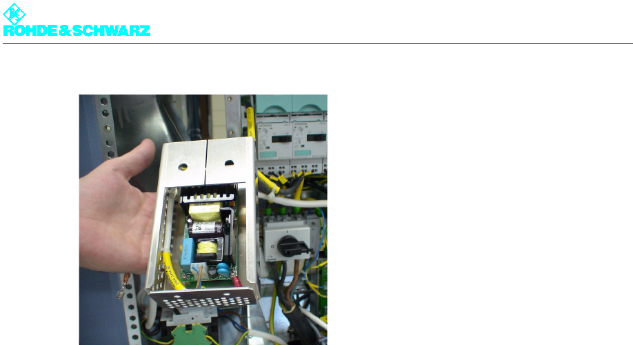
Fig. 11 Removing the power supply unit
4.5.2 Installing the Auxiliary Power Supply
)Replace the power supply unit by proceeding in the reverse order.