Acrodyne NW8201E DIGITAL TELEVISION BROADCAST TRANSMITTER User Manual 32 NV8202 26 04 06 01 00
Acrodyne Industries, Inc. DIGITAL TELEVISION BROADCAST TRANSMITTER 32 NV8202 26 04 06 01 00
Acrodyne >
Contents
- 1. Users Manual Part 1
- 2. Users Manual Part 2
- 3. Users Manual Part 3
- 4. Users Manual Part 4
- 5. Users Manual Part 5
- 6. Users Manual Part 6
- 7. Users Manual Part 7
- 8. Users Manual Part 8
- 9. Users Manual Part 9
- 10. Users Manual Part 10
- 11. Users Manual Part 11
- 12. USers Manual Part 12
- 13. Users Manual Part 13
- 14. Users Manual Part 14
- 15. Users Manual Part 15
- 16. Users Manual Part 16
- 17. Users Manual Part 17
- 18. Users Manual Part 18
- 19. Users Manual Part 19
- 20. Users Manual Part 20
Users Manual Part 17

Chapter 8 Service
2099.9595.72 - 8.15 - E-2
5 Transmitter Control Unit
You can replace the following transmitter control unit components:
NETCCU®
Rack controller
5.1 Replacing the NETCCU
5.1.1 Removing the NETCCU
Note Removing the NETCCU® does not affect transmission.
1. Switch off automatic line fuse F1.
2. Undo the two captive screws (Torx screwdriver No. 20) of both the NETCCU® and the
exciter on the front brackets (next to the handles).
3. Using the handles, slowly pull out the rackmount from the rack as far as it will go (the
guide rails will engage and lock in place).
4. Disconnect power cables at the rear of the NETCCU®.
5. Disconnect all cables at the rear of the NETCCU®.
ATTENTION!
Always make sure that the power supply is disconnected before commencing any service
work on the transmitter rack; this will prevent injury caused by electric shock and damage
to the instruments.
Chapter 8 Service
2099.9595.72 - 8.16 - E-2
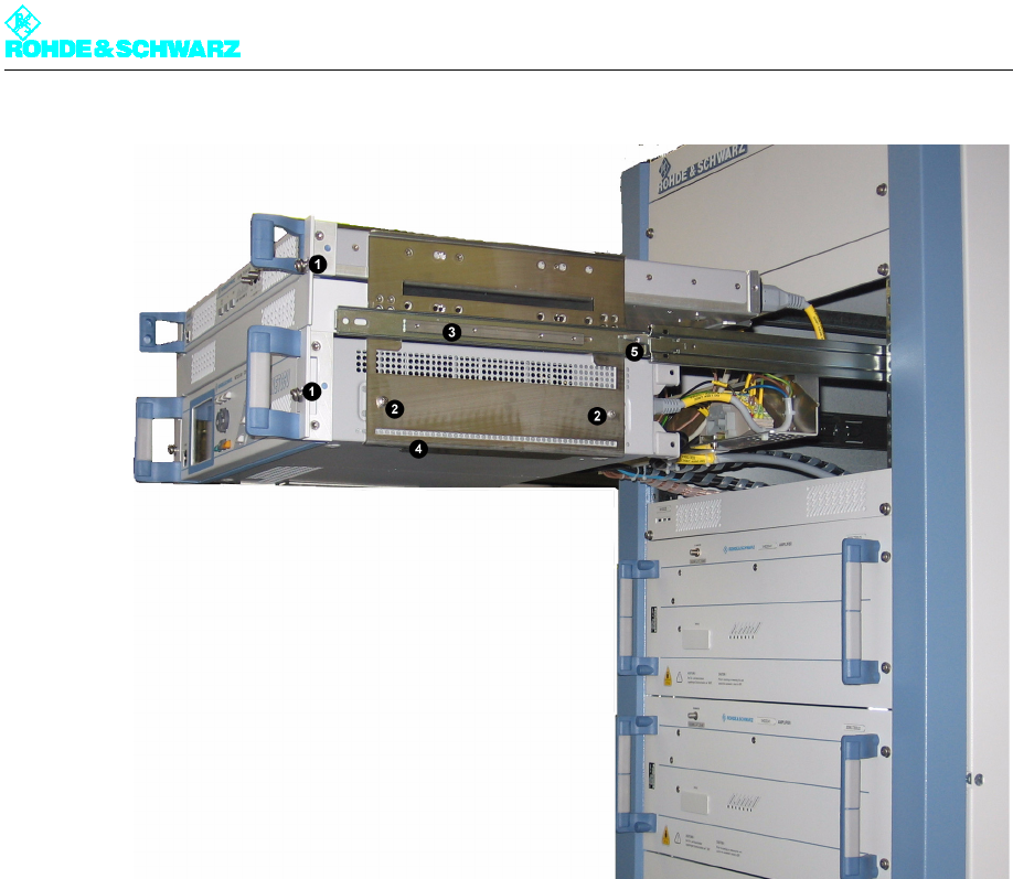
Fig. 12 Removing the NETCCU from the transmitter rack
1) Captive screws on the front panel of the built-in equipment (in this case exciter and NETCCU)
2) Screw-connections of the NETCCU on the rackmount
3) Guide rails
4) Support bracket for the NETCCU
5) Safety lever for undoing the latch of the guide rails
6. On both sides of the NETCCU® undo the two fixing screws (Phillips screwdriver No. 1)
from the rackmount.
Note It is advisable that two persons remove the NETCCU®. As soon as the support brackets
cease to support the NETCCU® while it is being pulled out using the handles, it needs
to be supported from below.
7. Pull the NETCCU® from the rackmount.
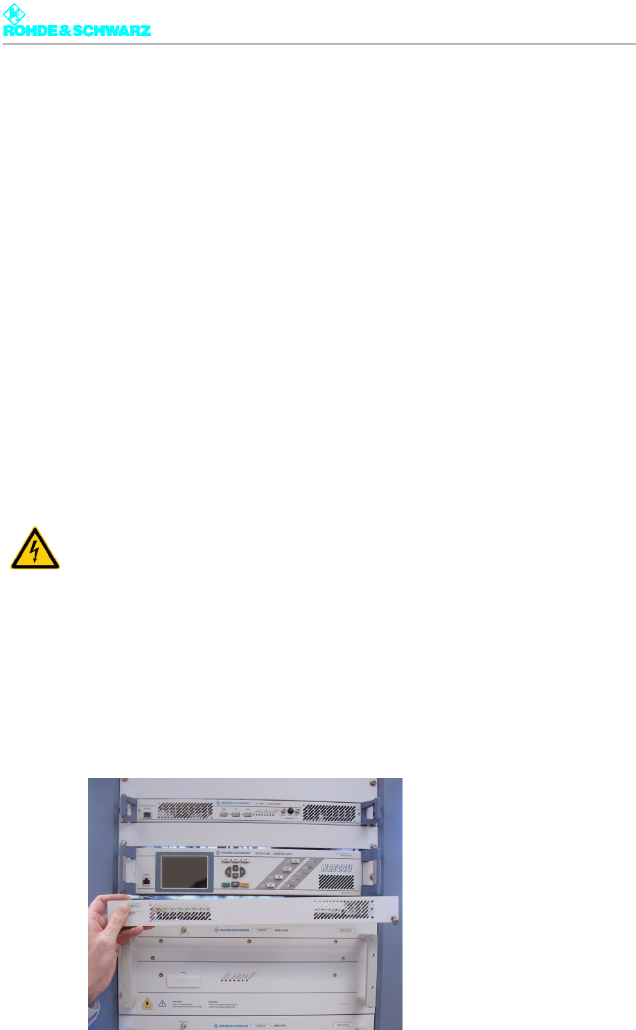
5.1.2 Preparing the NETCCU for Installation
The replacement NETCCU® is delivered as a desktop unit and must be prepared for instal-
lation as follows.
)Remove the protective rubber caps on the rear feet of the instrument.
Chapter 8 Service
2099.9595.72 - 8.17 - E-2
5.1.3 Installing the NETCCU
To install the amplifier in the transmitter, reverse the procedure used to remove it.
1. Slide the NETCCU® into the cabinet horizontally on the support brackets until the screw
holes on the cabinet and on the side panels of the NETCCU® match.
2. Fasten the NETCCU® with two screws on each side.
3. Connect the cables to the NETCCU® according to the labeling (see yellow cable col-
lars).
4. Undo the latch on the guide rails. Simultaneously press down the safety lever on the
right side and up on the left side and insert the rackmount into the rack.
5. Refasten the captive screws to the front panels of the NETCCU® and the exciter.
6. Switch the NETCCU® on again.
Note When installing the cables of the NETCCU® and putting the unit back into operation, refer
to the information in the transmitter manual.
5.2 Replacing the Rack Controller
5.2.1 Removing the Rack Controller
Note The rack controller is underneath the NETCCU®.
1. Remove the cover by undoing the two screws (Torx screwdriver No. 20).
ATTENTION!
Always make sure that the power supply is disconnected before commencing any service
work on the transmitter rack; this will prevent injury caused by electric shock and damage
to the instruments.
Chapter 8 Service
2099.9595.72 - 8.18 - E-2
2. Turn the two screws on the sides alternately (Torx screwdriver No. 20), a couple of turns
at a time.
This removes the rack controller from the rack without tilting.
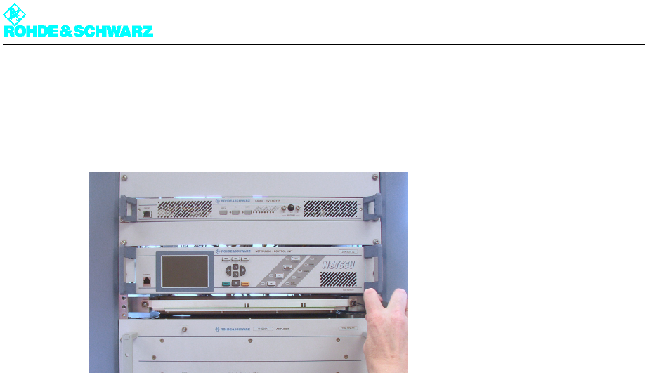
Fig. 13 Removing the rack controller from the transmitter rack
3. Remove the rack controller from the rack.
4. Disconnect the AC supply cable and all cabling from the rear of the rack controller.
5.2.2 Installing the Rack Controller
To install the unit in the transmitter, reverse the procedure used to remove it.
Note In the case of the cabling, note the labeling on the yellow cable collars.