Acrodyne NW8201E DIGITAL TELEVISION BROADCAST TRANSMITTER User Manual 32 NV8202 26 04 06 01 00
Acrodyne Industries, Inc. DIGITAL TELEVISION BROADCAST TRANSMITTER 32 NV8202 26 04 06 01 00
Acrodyne >
Contents
- 1. Users Manual Part 1
- 2. Users Manual Part 2
- 3. Users Manual Part 3
- 4. Users Manual Part 4
- 5. Users Manual Part 5
- 6. Users Manual Part 6
- 7. Users Manual Part 7
- 8. Users Manual Part 8
- 9. Users Manual Part 9
- 10. Users Manual Part 10
- 11. Users Manual Part 11
- 12. USers Manual Part 12
- 13. Users Manual Part 13
- 14. Users Manual Part 14
- 15. Users Manual Part 15
- 16. Users Manual Part 16
- 17. Users Manual Part 17
- 18. Users Manual Part 18
- 19. Users Manual Part 19
- 20. Users Manual Part 20
Users Manual Part 15
Chapter 8 Service
2099.9595.72 - 8.5 - E-2
4 Power Distribution
You can replace the following power distribution components:
Main switch (power supply terminal)
Motor protection switch
Automatic line fuse
Power distribution board
Auxiliary power supply
4.1 Replacing the Main Switch
4.1.1 Removing the Main Switch
To remove the main switch proceed as follows:
1. Using a Torx screwdriver No. 20, remove the front panel of the power distribution.
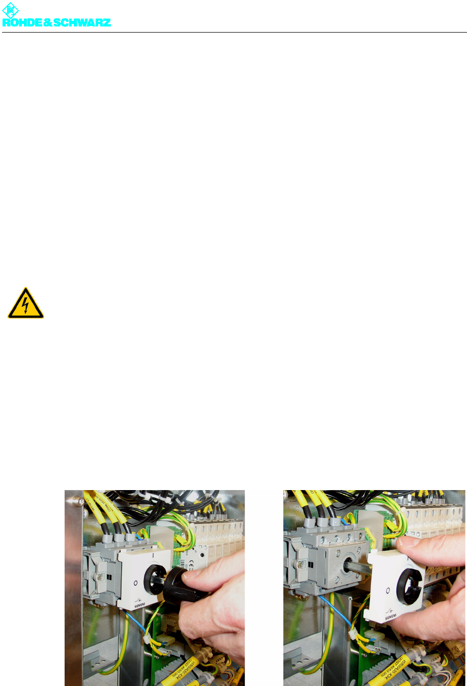
2. Unscrew the rotary knob and the main switch cover.
Fig. 2 Unscrewing the rotary knob and cover
3. Undo the screws on the switch housing (Phillips screwdriver No. 1) and remove the con-
nected cables.
ATTENTION!
Always make sure that the power supply is disconnected before commencing any service
work on the transmitter rack; this will prevent injury caused by electric shock and damage
to the instruments.
Chapter 8 Service
2099.9595.72 - 8.6 - E-2
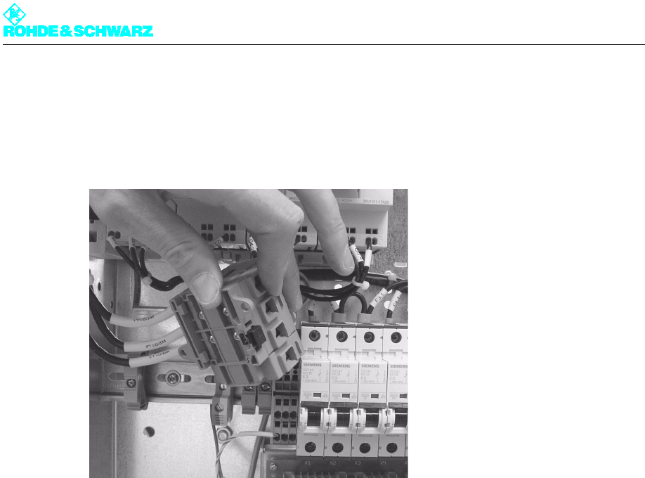
4. Undo the screws on the terminal rack on the left of the main switch and slide the terminal
rack to the left.
5. Pull forward the black stop lever on the underside of the main switch.
6. Carefully take out the main switch.
Fig. 3 Taking out the main switch
4.1.2 Installing the Main Switch
1. Replace the main switch by proceeding in the reverse order.
2. Insert the cables into the corresponding openings and fasten them with screws.
Note Notice how the cables are labeled and make sure they are in the right sequence, since
two of the three phase cables are the same color (black).
3. Measure the rotary field with the aid of a rotary field meter.
If the rotary field is correct, continue with the next step; if it is wrong, swap two wires from
the cable and measure the rotary field again.
4. Screw the main switch cover and the rotary knob back on.
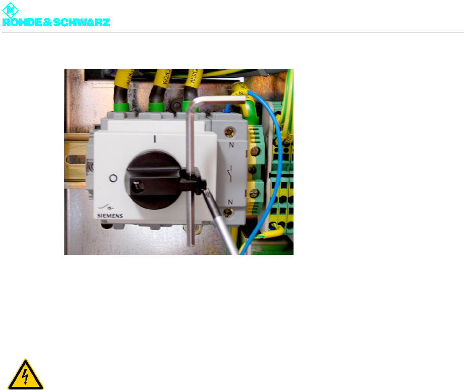
Note When working on the transmitter rack the main switch can be locked in the "OFF" posi-
tion (see next figure).
Chapter 8 Service
2099.9595.72 - 8.7 - E-2
Fig. 4 Main switch locked
4.2 Replacing the Motor Protection Switch
4.2.1 Removing the Motor Protection Switch
To remove the motor protection switch proceed as follows:
1. Using a Torx screwdriver No. 20, remove the front panel of the power distribution.
2. Pull the blue-green shorting plug forward.
If necessary you may use a screwdriver (No. 0) suited to the relatively high amounts of
force that are needed.
ATTENTION!
Always make sure that the power supply is disconnected before commencing any service
work on the transmitter rack; this will prevent injury caused by electric shock and damage
to the instruments.
Chapter 8 Service
2099.9595.72 - 8.8 - E-2
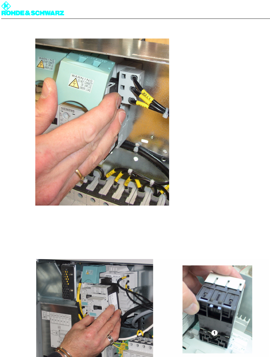
3. Press the motor protection switch sharply downward and pull it forward by the bottom
edge.
Because there is a spring clip behind the upper edge, you can only release the switch
downward.
1) Spring clip
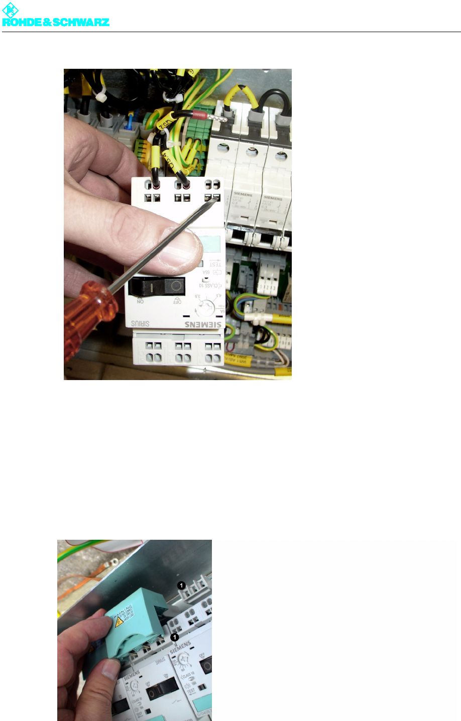
4. Use a screwdriver to open the cable clamps and pull out the connected cable (see fig-
ure).
Chapter 8 Service
2099.9595.72 - 8.9 - E-2
Fig. 5 Opening the cable clamp on the motor protection switch
4.2.2 Installing the Motor Protection Switch
)Replace the motor protection switch by proceeding in the reverse order.
Note When replacing, feed the shorting plug right in and push the switch into place with some
force.
Fig. 6 Installing the motor protection switch