Acrodyne NW8201E DIGITAL TELEVISION BROADCAST TRANSMITTER User Manual 32 NV8202 26 04 06 01 00
Acrodyne Industries, Inc. DIGITAL TELEVISION BROADCAST TRANSMITTER 32 NV8202 26 04 06 01 00
Acrodyne >
Contents
- 1. Users Manual Part 1
- 2. Users Manual Part 2
- 3. Users Manual Part 3
- 4. Users Manual Part 4
- 5. Users Manual Part 5
- 6. Users Manual Part 6
- 7. Users Manual Part 7
- 8. Users Manual Part 8
- 9. Users Manual Part 9
- 10. Users Manual Part 10
- 11. Users Manual Part 11
- 12. USers Manual Part 12
- 13. Users Manual Part 13
- 14. Users Manual Part 14
- 15. Users Manual Part 15
- 16. Users Manual Part 16
- 17. Users Manual Part 17
- 18. Users Manual Part 18
- 19. Users Manual Part 19
- 20. Users Manual Part 20
USers Manual Part 12

Broadcasting Division
2095.7346.32 - 4.0 - E-1
CHAPTER 4
COMMISSIONING
Printed in Germany

Chapter 4 Commissioning
2099.9595.72 - 4.01 - E-1
CONTENTS
1 General Information ......................................................................... 1
1.1 Preparations ....................................................................................................1
1.2 Preconditions ..................................................................................................2
1.3 Operating the NETCCU ..................................................................................2
2 Preparing to Put a Transmitter into Operation ............................. 3
2.1 Preparing for Local Operation .......................................................................3
2.2 Checking and Setting System and Operating Parameters .........................3
2.3 NETCCU ...........................................................................................................3
2.3.1 Switching on the NETCCU ...........................................................................3
2.3.2 Changing the User Type ..............................................................................3
2.3.3 Carrying out Basic Settings ..........................................................................4
2.3.4 Entering Default Values for the Front Ethernet Connection .........................5
2.4 Setting the Transmitter Type .........................................................................6
2.5 Entering Exciter Settings ...............................................................................7
2.5.1 Setting the TV Standard ...............................................................................7
2.5.2 Configuring Input Interfaces .........................................................................8
2.5.2.1 Specifying the Data Format for Data Streams HP 1 or HP 2 ............................. 8
2.5.2.2 Specifying the Data Format for Low Priority Data Streams LP 1 or LP 2 ........... 9
2.5.2.3 Setting Automatic Input Switchover .................................................................. 10
2.5.3 Entering Settings for Signal Encoding ........................................................12
2.5.3.1 Selecting the TPS Source ................................................................................ 12
2.5.3.2 Setting the TPS Parameters Manually ............................................................. 13
2.5.3.3 Checking Delays at SFN Delay - SFN Mode Only ........................................... 15
2.5.4 Switching Off the Precorrector ...................................................................16
2.5.5 Setting the Transmitter Frequency .............................................................17
2.5.6 Setting RF Output .......................................................................................18
2.5.7 I/Q adjustment ............................................................................................19
2.5.8 Specifying Behavior on Failure of a Reference Source ..............................20
2.6 Entering Output Stage Settings ..................................................................21
2.6.1 Preparing the Output Stage ........................................................................21
2.7 Setting the Transmitter Output Power ........................................................22
2.8 Calibrating Power Displays .........................................................................23
2.8.1 Calibrating Forward and Reflected Power Displays ...................................23

Chapter 4 Commissioning
2099.9595.72 - 4.02 - E-1
3 Completion of the Procedure for Putting the Transmitter into Ope-
ration 25
3.1 Final Steps ....................................................................................................25
3.1.1 Checking the Output Stage Status Display ................................................25
3.1.2 Checking the Exciter Status Display ..........................................................26
3.1.3 Checking the NETCCU Status Display ......................................................26
3.2 Clearing the Event Memory .........................................................................27
4 Precorrection ................................................................................. 29
4.1 Functions of the Non-Linear Precorrector .................................................29
4.1.1 General .......................................................................................................29
4.1.2 Linear Basic Precorrection .........................................................................29
4.1.3 Non-Linear Frequency Responses .............................................................30
4.1.4 Dynamic Precorrection (ATV Split Only) ....................................................30
4.1.5 Audio Phase Precorrection (ATV Combined Only) ....................................30
4.2 General Information on Operating the Precorrector .................................30
4.3 Performing Precorrection ............................................................................30
4.3.1 General Requirements ...............................................................................31
4.3.2 Determining System Levels ........................................................................31
4.3.3 Precorrection Procedure ............................................................................32
4.3.3.1 Starting Precorrection ....................................................................................... 32
4.3.3.2 Phase Precorrection ......................................................................................... 33
4.3.3.3 Amplitude Precorrection ................................................................................... 34
4.3.3.4 Frequency Dependent Precorrection ............................................................... 35
4.3.3.5 Fine Adjustment Using an Existing or Preset Characteristic ............................ 37

Chapter 4 Commissioning
2099.9595.72 - 4.1 - E-1
1 General Information
Transmitters are put into operation by means of the graphical interface of the NETCCU®.
1.1 Preparations
Before you can put a transmitter into operation it must first have been fully installed. Check
the following list to ensure that all connections have been correctly made:
)Check whether all the modules delivered have been correctly installed and connected
as necessary.
)Check whether the transmitter has been correctly connected to the AC supply. Please
note:
Connection in general
– Power feed, rack ground, air cooling system, 50 Ω test load (dummy antenna) in ap-
propriate cases, power-handling capacity P > nominal transmitter power, directional-
coupler filter, matrix or antenna
Connections involving RF carrier loops and fault messages
– Set up the following jumpers/connections on the power distribution board connectors
(the name of the connector concerned is printed on the board).
RF carrier loop, operation - X41 1-2 RF carrier loop, standby - X41 3-4 Fault message
for rack absorber - X42 1-2 Fault message for system absorber - X42 3-4 (In the case
of multirack transmitters, the overtemperature switches of the RF absorbers are con-
nected to the absorber fault message inputs.)Fault message for external cooling -
X44 1-2
If customer instruments having interlock circuit outputs such as control monitoring
are present, you can loop in these instruments in place of the wire jumpers.
Emergency-off switch X7 (if available)
Motor protection switches to be set at 3 A
)Check the direction of the rotary field from the AC supply voltage.
)Switch off the main disconnect switch Q1, together with all motor protection switches
and automatic line fuses.
)Check that all screws and nuts are securely fastened, especially those on the transmitter
RF output.

Chapter 4 Commissioning
2099.9595.72 - 4.2 - E-1
1.2 Preconditions
1. Before switching on the transmitter, check whether the exciter is set to the correct fre-
quency (consistent with any diplexer or bandpass filter that may be connected).
If the transmission frequency is not yet known, the transmitter should remain switched
off unti the frequency is set.
2. Connect an antenna to the RF output.
Switching on the transmitter
Switch on the transmitter as follows:
1. Turn the main disconnect switch on (Q1).
2. Switch on the exciter (F1 or F2).
The exciter should boot up.
3. Switch on the NETCCU® (F3).
The NETCCU® should boot.
4. Switch on the auxiliary power supply (F5).
5. Switch on the fan fuse for fan 1 (F6) and fan 2 (F7).
6. If necessary switch on additional (F4) and peripheral units (F8).
1.3 Operating the NETCCU
Note Detailed information on operating the NETCCU® can be found in the "Operation" section.

Chapter 4 Commissioning
2099.9595.72 - 4.3 - E-1
2 Preparing to Put a Transmitter into Operation
Local operation of the NETCCU® includes all the main information calls for the most impor-
tant system parameters and their settings, complete with intuitive graphical menus.
Remote operation via a web browser is possible only if a PC or notebook is connected to
the NETCCU® front panel.
2.1 Preparing for Local Operation
To prepare for local operation proceed as follows:
)Press the LOCAL key on the NetCCU.
The corresponding yellow LED should come on.
2.2 Checking and Setting System and Operating
Parameters
In order to bring the transmitter into operation, you must check and set the following system
and operating parameters.
2.3 NETCCU
2.3.1 Switching on the NETCCU
)Connect the NETCCU® to the mains supply.
After a few seconds, the unit boots and the input screen indicates when it is ready for
use.
Local operation of the NETCCU® includes all the main information calls for the most impor-
tant system parameters and their settings, complete with intuitive graphical menus.
Remote operation via a web browser is possible only if a PC or notebook is connected to
the NETCCU® front panel.
2.3.2 Changing the User Type
To configure the transmitter by means of the NETCCU® you must have configuration rights.
To log on proceed as follows:
Chapter 4 Commissioning
2099.9595.72 - 4.4 - E-1
1. From the menu, select the Change User menu point.
The Logon window opens, displaying the currently valid user type.
2. Call the context menu again and select user type Configuration.
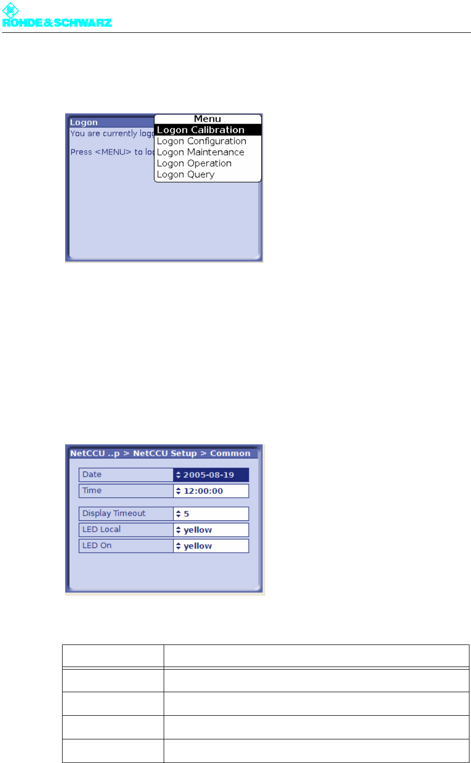
2.3.3 Carrying out Basic Settings
After switching on the NETCCU®, you can enter the basic system settings.
)Select NetCCU > Setup > NetCCU Setup > Common.
The Common window opens.
You can enter the following settings in the Common window:
Selection Description
Date Date
Time Local time
Display Timeout Time in minutes after which the display switches off (standby)
LED Local Color of the Local LED on the front panel of the NETCCU (yellow, green)
Chapter 4 Commissioning
2099.9595.72 - 4.5 - E-1
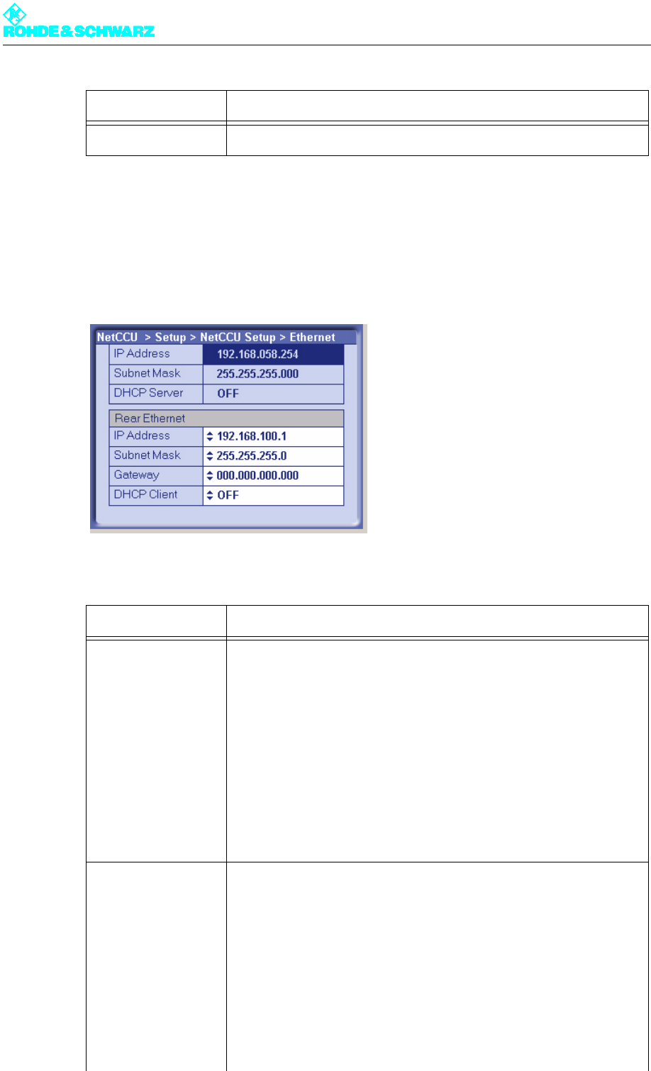
2.3.4 Entering Default Values for the Front Ethernet Connection
)Select NetCCU > Setup > NetCCU Setup > Ethernet.
The Ethernet window opens.
You can enter the following settings in the Ethernet window:
LED On Color of the On LED on the front panel of the NETCCU (yellow, green)
Selection Description
Front Ethernet
IP Address The IP address (192.168.58.254) of the NETCCU is factory-set and can-
not be changed. To make an external connection to a PC/Laptop the
appropriate address must be entered: The first three segments (of the
above IP address) stay the same, but a value < 250 must be entered for
the last block of numbers.
Subnet mask The setting for the NETCCU subnet mask is factory-set and cannot be
changed. For an external connection, this same setting must also be
entered on a PC or laptop.
DHCP Server This function is not implemented in this version.
Rear Ethernet Manual settings should only be entered in Offline mode (context menu:
Edit Offline) and should then be activated by means of Submit Changes
(context menu).
IP Address Entry of a valid IP address. The IP address 192.168.058.254 is not to be
used.
Subnet mask The setting for the NETCCU subnet mask is factory-set, but can be
changed if necessary. For an external connection, this setting must be
defined in the network.
Gateway Entry of a gateway address (assigned by the network administrator).
Selection Description
Chapter 4 Commissioning
2099.9595.72 - 4.6 - E-1
Note The system must be restarted in order to implement the changes.
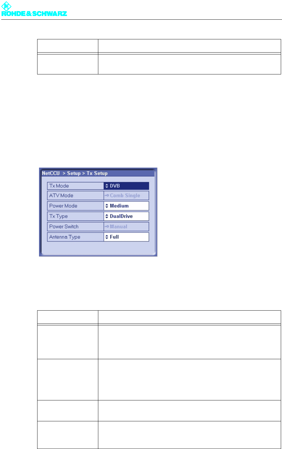
2.4 Setting the Transmitter Type
)Select NetCCU > Setup > TX Setup.
The Tx Setup window opens.
You can use the TX Setup window to make system-specific settings and to define standby
behavior.
The table below describes the adjustable parameters:
DHCP Client ON: The IP address is automatically retrieved from the net.
OFF: The IP address has to be entered manually (see above).
Setting item Description
TX Mode Selection of the transmitter standard
– FM: analog sound broadcasting standard
– ATV: analoger TV standard
– DVB: digital TV standard
ATV Mode Selected only when setting ATV under TX Mode
– Comb Single: picture signal and sound signal are transmitted via one
amplifier (same channel) (single = 1 sound carrier)
– Comb Dual: picture signal and sound signal are transmitted via one
amplifier (same channel) (dual = 2 sound carriers)
Power Mode Setting for medium-power transmitters
– Medium
TX Type For setting the standby behaviour:
– Single TX: standby system (see below)
– Dual Drive: standby system (see below)
Selection Description
Chapter 4 Commissioning
2099.9595.72 - 4.7 - E-1
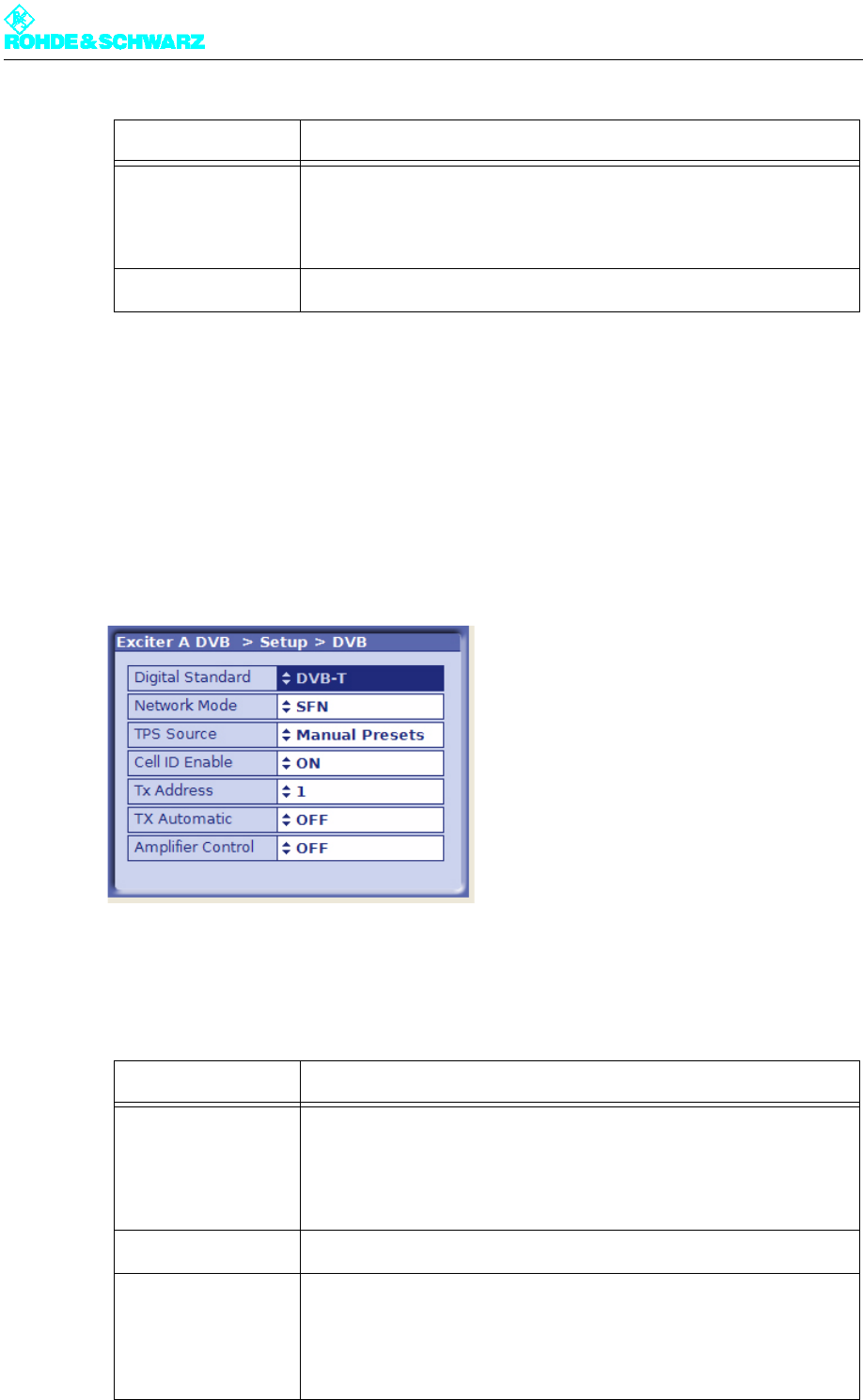
2.5 Entering Exciter Settings
2.5.1 Setting the TV Standard
1. Select Exciter A DVB > Setup > DVB.
The Setup > DVB window opens.
2. Select the wanted TV standard.
The table below describes the parameters in detail:
Power Switch Setting of the hardware configuration for antenna switchover. The fol-
lowing options are available:
– "Manual" for switching over the antenna manually
– "Automatic" for switching over the antenna electronically
Antenna Type Country-specific setting for the antenna type; the default setting is Full
Setting item Description
Digital Standard Selection of the digital TV standard: DVB-T, DVB-H or ATSC
Switching over from DVB-T or DVB-H after ATSC is followed by a
restart. At the same time signal processing is switched over and the
associated user interface is loaded.
Network Mode Selection of the network operating mode: SFN or MFN
TPS Source Setting the source for the TPS parameters: MIP or manual presets (see
section "DVB Parameters > TPS")
The TPS source can also be set in the DVB Parameters > TPS menu
window.
Setting item Description

Chapter 4 Commissioning
2099.9595.72 - 4.8 - E-1
2.5.2 Configuring Input Interfaces
2.5.2.1 Specifying the Data Format for Data Streams HP 1 or HP 2
1. Select Exciter A DVB > Input > Input Config HP.
The Input > Input Config HP window opens.
2. Go to Presel. Mode and select the value Auto for Input HP 1 and Input HP 2.
The data format is recognized automatically.
The table below describes the parameters in detail:
Cell ID Enable Switching cell ID signaling on or off in the TPS
The cell ID itself is set in the DVB Parameters > TPS menu window. It
can also be retrieved from the MIP.
Tx Address Setting the transmitter address; address range: 0 to 65535
Setting the transmitter is a precondition to reading Tx information (trans-
mitter-specific settings) from the MIP. However, the information is only
used if Tx Automatic is enabled.
Tx Automatic Activates and deactivates the Tx Automatic
When the automatics are enabled (and the transmitter address is set)
the following Tx parameters are retrieved from the MIP:
Time Offset, Frequency Offset and Cell ID
Amplifier Control Activates and deactivates the amplifier control unit
In R&S low-power transmitters wothout NETCCU the exciter can take
over amplifier control. This function is implemented with effect from soft-
ware release V1.2.0.
Setting item Description
Chapter 4 Commissioning
2099.9595.72 - 4.9 - E-1
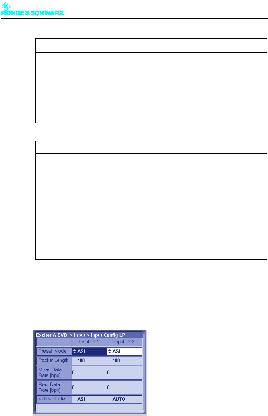
2.5.2.2 Specifying the Data Format for Low Priority Data Streams LP 1 or LP 2
1. Select Exciter A DVB > Input > Input Config LP.
The Input > Input Config LP window opens.
Setting item Description
Presel. Mode
[Input HP1/Input HP2]
Setting the data format for the data streams HP 1 or HP 2 (operating
and standby signals) on inputs TS 1 IN or TS 3 IN.
The options are as follows:
– AUTO: The data format is automatically recognized
– ASI: Manual setting for an ASI transport stream
– SMPTE: Manual setting for a SMPTE transport stream
In the case of hierarchical coding the operating or standby signal for the
high priority (HP) stream is fed via the two inputs HP 1 and/or HP 2.
Display Description
Packet Length
[Input HP1/Input HP2]
Display showing the packet length detected at the respective input
Meas.Data Rate [bps]
[Input HP1/Input HP2]
Display showing the measured data rate at the respective input. In MFN
mode the net data rate is displayed (without null packets).
Req. Data Rate [bps]
[Input HP1/Input HP2]
Display for checking the measured data rate. Depending on the chosen
network mode, the following information is displayed:
–MFN: Maximum data processing rate
–SFN: Required data rate
Active Mode Display showing the data format detected or set at the respective input:
– ASI: As described
– SMTPE: As described
– Auto: Auto is selected and there is no data stream

Chapter 4 Commissioning
2099.9595.72 - 4.10 - E-1
2. Go to Presel. Mode and select the value Auto for Input LP 1 and Input LP 2.
The data format is recognized automatically.
The table below describes the parameters in detail:
2.5.2.3 Setting Automatic Input Switchover
1. Select Exciter A DVB > Input > Input Automatic.
The Input > Input Automatic window opens.
Setting item Description
Presel. Mode
[Input LP1/Input LP2]
In the case of hierarchical coding: Setting the data format for the low pri-
ority data streams LP 1 or LP 2 (operating and standby signals) on
inputs TS 2 IN or TS 4 IN.
The options are as follows:
– AUTO: The data format is automatically recognized
– ASI: Manual setting for an ASI transport stream
– SMPTE: Manual setting for a SMPTE transport stream
Display Description
Packet Length
[Input LP1/Input LP2]
Display showing the packet length detected at the respective input
Meas.Data Rate [bps]
[Input LP1/Input LP2]
Display showing the measured data rate at the respective input. In MFN
mode the net data rate is displayed (without null packets).
Req. Data Rate [bps]
[Input LP1/Input LP2]
Display for checking the measured data rate. Depending on the chosen
network mode, the following information is displayed:
–MFN: Maximum data processing rate
–SFN: Required data rate
Active Mode Display showing the data format detected or set at the respective input:
– ASI: As described
– SMTPE: As described
– Auto: Auto is selected and there is no data stream

Chapter 4 Commissioning
2099.9595.72 - 4.11 - E-1
2. Activate automatic input switchover if required, and enter the appropriate settings.
The table below describes the parameters in detail:
Setting item Description
Preselect Input For preselecting the inputs
– INPUT 1: The operating input is TS 1 IN. In the case of hierarchical
coding, TS 2 IN is used as a second operating input for the low prior-
ity stream.
– INPUT 2: The operating input is TS 3 IN. In the case of hierarchical
coding, TS 4 IN is used as a second operating input for the low prior-
ity stream.
Autoswitch Switches the automatic input switchover on or off.
In the event of a failure on the active operating input, automatic switcho-
ver to the standby input takes place. The automatic switchover mode is
defined by the following parameter settings.
Seaml. Switching Switches seamless input switchover on or off.
– ON: In the event of a failure, input switchover takes place without a
break in transmission, provided the data streams are synchronized at
the operating and standby inputs.
– OFF: For the purpose of testing the automatic input switchover, the
Seaml. Switching function can be deactivated.
The function has no effect when automatic input switchover is deacti-
vated.
Priority Selection of the priority mode.
– EQUAL: The preselected operating input and standby input have the
same priority. Once a switchover has taken place there is normally no
return switchover to the operating input which previously failed.
– PRIOR: The preselected operating input is the priority input. Once a
switchover has taken place the system switches back to the prese-
lected operating input as soon as the signal reappears.
Check Time Forward For setting a delay time (0 to 60 s) which must elapse before the
switchover to the standby input takes place in the event of a failure on
the operating input.

Chapter 4 Commissioning
2099.9595.72 - 4.12 - E-1
2.5.3 Entering Settings for Signal Encoding
2.5.3.1 Selecting the TPS Source
1. Select Exciter A DVB > DVB Parameters > TPS.
The DVB Parameters > TPS window opens.
Check Time Back For setting a delay time (0 to 60 s) which must elapse before switching
back to the operating input after switching over from the standby input
(which is no longer active).
The function has no effect if the priority mode is set to EQUAL.
On Input Fail For setting the behavior in the event of a defective input signal (synchro-
nization error)
– No Mute: The output signal is not suppressed
– Mute: The output signal is suppressed if the data rate is incorrect or
the MIP is faulty (recommended for SFN)
Display Description
Seamless Switching Status display for indicating whether the input streams are synchronized
on the operating and standby inputs (precondition for seamless input
switchover).
Setting item Description
Chapter 4 Commissioning
2099.9595.72 - 4.13 - E-1
2. Select the Manual Presets setting for TPS Source if you wish to configure the TPS pa-
rameters manually
or
the MIP setting if you prefer the TPS parameters to be retrieved from the MIP.
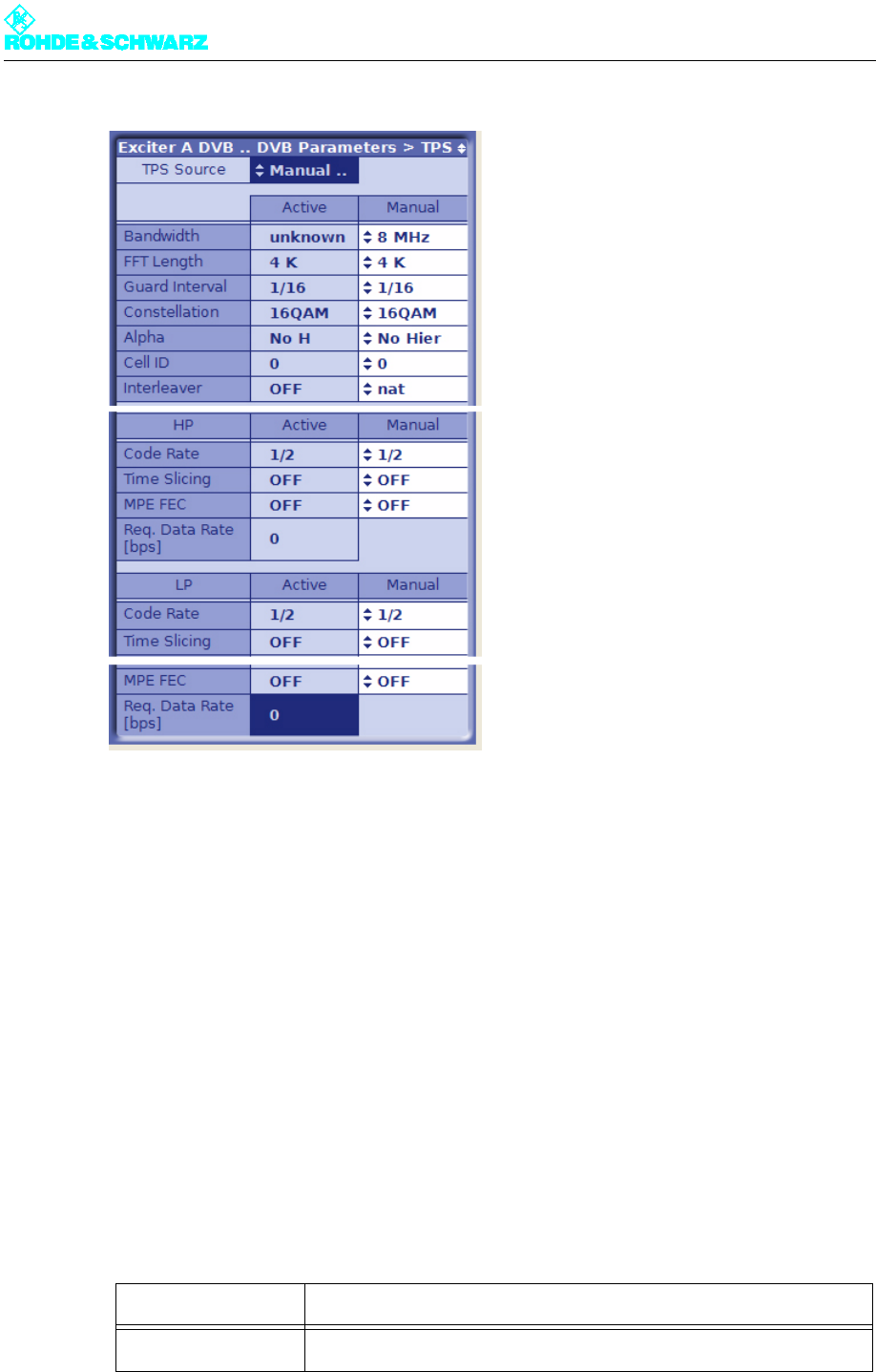
2.5.3.2 Setting the TPS Parameters Manually
Note You can only configure the TPS parameters manually if the Manual Presets setting is se-
lected for TPS Source.
1. Select Exciter A DVB > DVB Parameters > TPS.
The DVB Parameters > TPS window opens.
2. Set the TPS parameters.
The table below describes the variable parameters in detail:
Setting item Description
TPS Source Setting the source for the TPS parameters: MIP or manual presets

Chapter 4 Commissioning
2099.9595.72 - 4.14 - E-1
Display/
setting item
Description of the
active or manually set TPS parameters
Bandwidth Signal bandwidth
Display/setting: 5, 6, 7 or 8 MHz
FFT Length IFFT length
Display/setting: 2k or 8k; also 4k in the case of DVB-H
Guard Interval Guard interval
Display/setting: 1/4, 1/8, 1/16 or 1/32
Constellation Modulation mode
Display/setting: QPSK, 16QAM or 64QAM
In the case of hierarchical coding the value refers to the sum of the HP
and LP stream constellation points; possible values are therefore:
16QAM or 64QAM
Alpha Hierarchy parameter α
Display/setting:
– No Hier: Non-hierarchical coding
– 1 H: Hierarchical coding with α = 1
– 2 H: Hierarchical coding with α = 2
– 3 H: Hierarchical coding with α = 3
1 H, 2 H or 3 H activates the hierarchical coding mode. However, this is
only possible if Constellation is set to 16QAM or 64QAM.
Cell ID Cell ID
Display/setting: 0x0000 to 0xFFFF
The Cell ID can only be retrieved from the MIP if the Tx Automatic is
activated and the Tx address is correctly set (see section "Setup >
DVB").
For the purpose of signaling in the output signal (TPS), Parameter Cell
ID Enable must also be activated (see section "Setup > DVB").
Interleaver Interleaver
Display/setting:
– nat: Default setting ("native") with normal function for DVB-T
– in depth: 8k interleaving for DVB-H at IFFT lengths of 2k and 4k for
improved transmission reliability (DVB-H parameter)
Code Rate [HP/LP] Internal code rate (separate for HP and LP stream)
Display/setting: 1/2, 2/3, 3/4, 5/6 or 6/7
Time Slicing [HP/LP] Time slicing flag (DVB-H parameter)
Display/setting separate for HP and LP stream:
– OFF: Default setting; no signaling via flag
– ON: A flag is set in the broadcast DVB signal. This flag informs the
receiver that at least one service in the DVB-H data stream uses time
slicing.
Chapter 4 Commissioning
2099.9595.72 - 4.15 - E-1
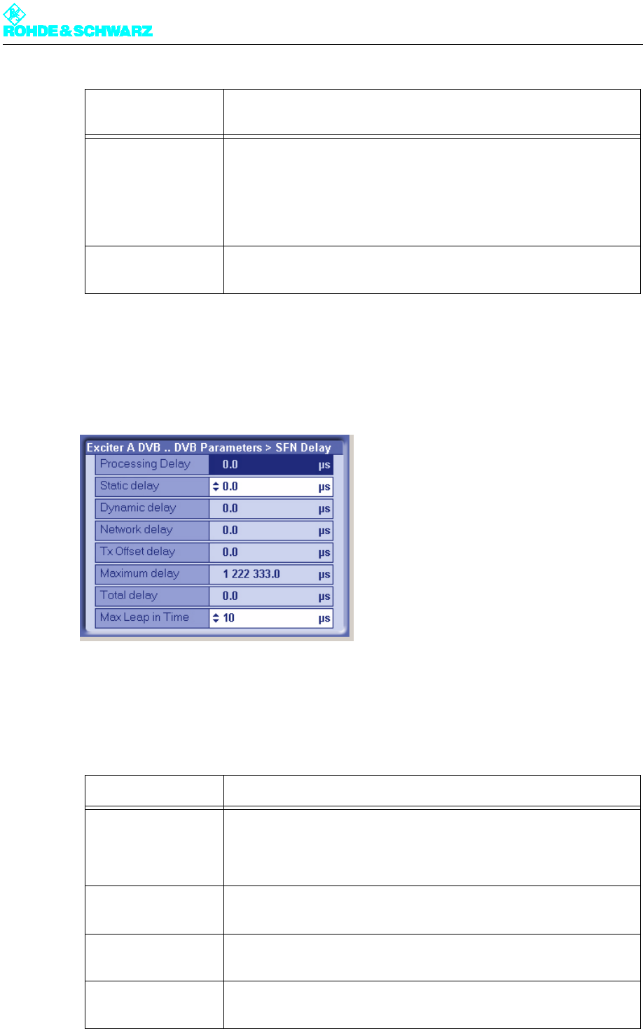
2.5.3.3 Checking Delays at SFN Delay - SFN Mode Only
1. Select Exciter A DVB > DVB Parameters > SFN Delay.
The DVB Parameters > TPS > SFN Delay window opens.
2. If necessary, enter a static delay and check whether the dynamic delay is in the range
0 to 1second (if not the single-frequency condition is violated).
The table below describes the variable parameters in detail:
MPE FEC [HP/LP] MPE FEC flag (DVB-H parameter)
Display/setting separate for HP and LP stream:
– OFF: Default setting; no signaling via flag
– ON: This flag informs the receiver that at least one service in the
DVB-H data stream uses forward error correction for MPE (multipro-
tocol encapsulation).
Req. Data Rate
[HP/LP]
Display showing the required data rate:
cf. section "Input > Input Config HP"
Display Description
Maximum Delay Period of time between the signal leaving the play-out center (MIP
inserter) and its regular transmission at the transmitting antenna. This
delay is set in the MIP inserter and serves as a basis for all the transmit-
ters in the SFN.
Network Delay Signal propagation time between the play-out center (MIP inserter) and
the exciter input. This delay depends on the transmission path used.
Processing Delay Minimum signal transit time through the exciter. This delay depends on
the DVB transmission parameters.
Dynamic Delay Period of time by which signal processing is artificially delayed so that
the desired time of transmission is obtained.
Display/
setting item
Description of the
active or manually set TPS parameters

Chapter 4 Commissioning
2099.9595.72 - 4.16 - E-1
2.5.4 Switching Off the Precorrector
1. Select Exciter A DVB > Precorrection.
The Precorrection window opens.
2. Switch all precorrectors off.
The table below describes the variable parameters in detail:
Total Delay Actual signal transit time through the exciter. This is derived from the
sum of the processing delay and the dynamic delay.
Tx Offset Delay The offset in time of transmission (positive or negative) sent to the MIP
for the individual transmitter site, relative to the regular time of transmis-
sion specified by the maximum delay.
For the purpose of display and activation, the Tx Automatic must be
enabled and the Tx address of the transmitter must agree (see section
"Setup > DVB").
If Tx offset delay and static delay are both present at the same time,
their effects combine.
Setting item Description
Static Delay The offset in time of transmission (positive or negative) set manually for
the individual transmitter site, relative to the regular time of transmission
specified by the maximum delay. The static delay can be used to com-
pensate for manufacturing differences between transmitter systems.
If static delay and Tx offset delay are both present at the same time,
their effect combines.
Max Leap in Time In relation to the computed time of transmission, this is the maximum
leap in time that can be corrected without a break in transmission.
Default setting: 10 µs
Display Description
Chapter 4 Commissioning
2099.9595.72 - 4.17 - E-1
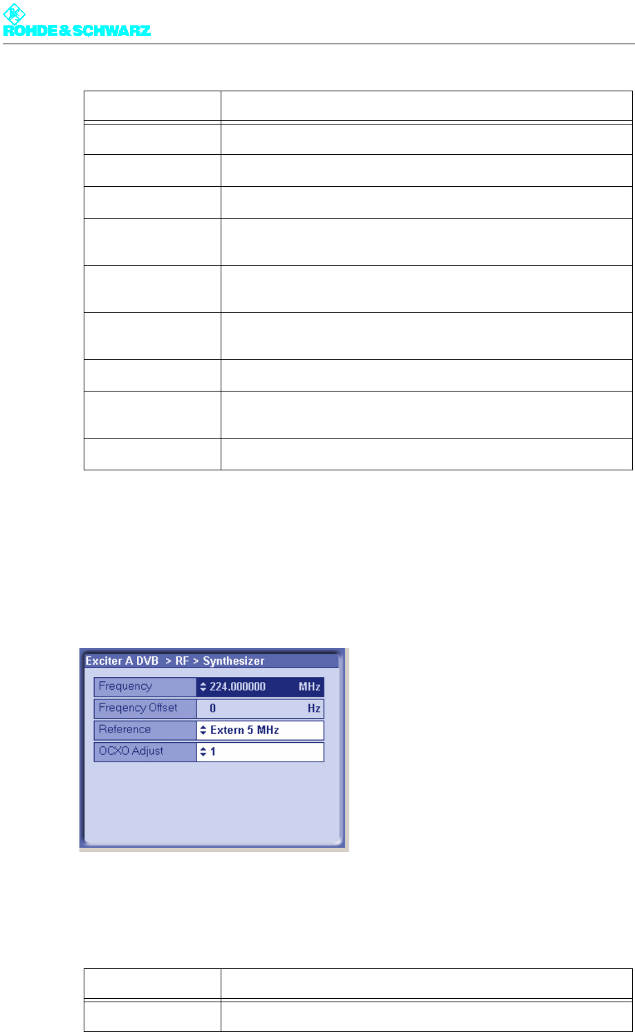
2.5.5 Setting the Transmitter Frequency
1. Select Exciter A DVB > RF > Synthesizer.
The RF > Synthesizer window opens.
2. Enter the desired settings.
The table below describes the variable parameters in detail:
Setting item Description
Nonlinear Correction Switches the entire nonlinear correction on or off.
– Amplitude Switches the amplitude correction in the nonlinear corrector on or off.
– Phase Switches the phase correction in the nonlinear corrector on or off.
– Nonlinear Fre-
quency
Switches the entire nonlinear frequency response correction on or off.
– Point 1 Switches the frequency response influence on branch 1 on or off (non-
linear frequency response correction).
– Point 2 Switches the frequency response influence on branch 2 on or off (non-
linear frequency response correction).
Linear Correction Switches the entire linear correction on or off.
– Amplitude Switches the amplitude frequency response correction in the linear cor-
rector on or off.
– Group Delay Switches the group delay correction in the linear corrector on or off.
Setting item Description
Frequency Setting the channel center frequency

Chapter 4 Commissioning
2099.9595.72 - 4.18 - E-1
2.5.6 Setting RF Output
1. Select Exciter A DVB > RF > Output.
The RF > Output window opens.
2. For normal transmission operation, enter the following settings:
Note For Output Attenuation use the preselected value 0dB.
Reference Selecting the reference source for stabilization of the frequency pro-
cessing (reference frequency source). The following settings are possi-
ble:
– Internal: Operation without an external reference frequency source.
– External 5 MHz: Operation with an external 5 MHz reference.
– External 10 MHz: Operation with an external 10 MHz reference.
– External 1pps: Operation with an external time reference (1 pps)
The same setting options can be found in the RF > Reference menu
window.
OCXO adjust Setting for adjusting the internal OCXO frequency (for "Internal" mode).
The same setting options can be found in the RF > Reference menu
window.
Display Description
Frequency offset Any frequency offset is added straight to the channel center frequency.
The frequency offset transferred in the MIP is addressed to a particular
transmitter in the network and is evaluated only if the Tx address set in
the Setup > DVB menu window is the correct recipient. For the purpose
of display and activation the Tx Automatic also needs to be enabled
(see section "Setup > DVB").
Setting item Description

Chapter 4 Commissioning
2099.9595.72 - 4.19 - E-1
The table below describes the variable parameters in detail:
2.5.7 I/Q adjustment
Note When delivered, the I/Q modulator is factory-adjusted so that no customer intervention is
normally required.
If a further I/Q adjustment is needed at a later time, the actuators in the RF > IQ Adjust
menu window can be used for this purpose.
Setting item Setting
Regulation ON
Output Attenuation 0 dB (for NW8201 -
9dB)
RF Slope 0 %
Modulation Slope 0 %
Setting item Description
RF Output Enables (On) or disables (Off) the RF output.
Regulation Activates (On) or activates (Off) the output level control. During trans-
mission operation, control must be enabled.
The current status of the related level adjuster is displayed as a percent-
age under RF > RF Monitor > AGC Exciter.
Manual RF Level Manual setting of the output level; the setting has an effect only if output
level control is deactivated.
The current status of the related level adjuster is displayed as a percent-
age under RF > RF Monitor > AGC Exciter.
Output Attenuation For level adaptation purposes, an integrated attenuator with a value of
3 dB, 6 dB or 9 dB can be connected. This has no influence on the level
control.
RF Slope Correction of a slope of the amplitude frequency response in the spec-
trum for equalizing subsequent components (output stage, filter).
Modulation Slope Correction of a curvature of the amplitude frequency response in the
spectrum for equalizing subsequent components (output stage, filter).
Display Description
AGC Regulation Displays the level of the output level control
Chapter 4 Commissioning
2099.9595.72 - 4.20 - E-1
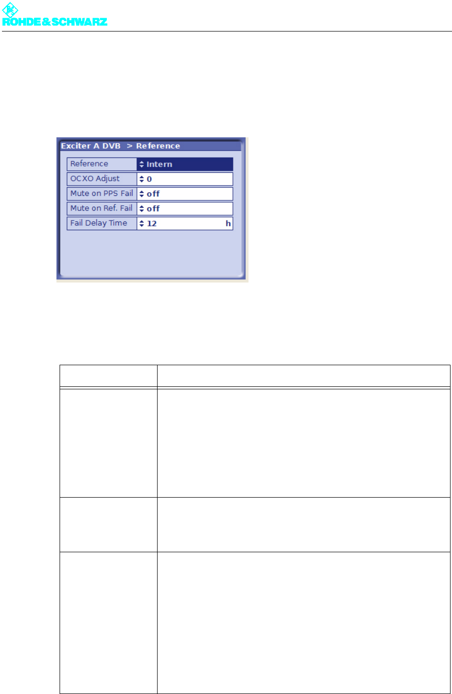
2.5.8 Specifying Behavior on Failure of a Reference Source
1. Select Exciter A DVB > Reference.
The Reference window opens.
2. Select the desired settings:
The table below describes the variable parameters in detail:
Setting item Description
Reference Selection of the reference frequency source. The following settings are
possible:
– Internal: Operation without an external reference frequency source.
– External 5 MHz: Operation with an external 5 MHz reference.
– External 10 MHz: Operation with an external 10 MHz reference.
– External 1pps: Operation with an external time reference (1 pps)
The same setting options can be found in the RF > Synthesizer menu
window.
OCXO Adjust Setting for adjusting the internal OCXO frequency (for "Internal" mode).
The same setting option can be found in the RF > Synthesizer menu
window.
Mute on PPS Fail For setting the behavior in SFN mode in the event of failure of the exter-
nal time reference. The following settings are possible:
– off: The output signal is not suppressed.
– only at startup: The output signal is suppressed at startup until a valid
1-pps signal is detected; if the 1-pps signal fails after synchronization,
the output signal is no longer suppressed
– after fail delay time: The output signal is suppressed if the 1-pps sig-
nal fails for longer than the period specified at Fail Delay Time
This is the recommended setting for operation in SFN mode.
Chapter 4 Commissioning
2099.9595.72 - 4.21 - E-1
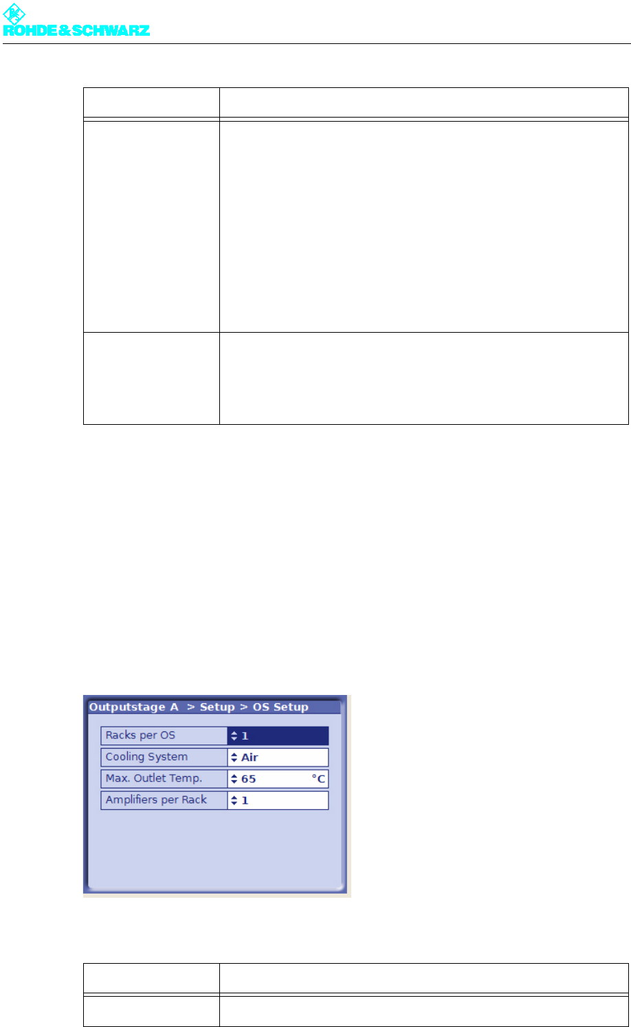
2.6 Entering Output Stage Settings
2.6.1 Preparing the Output Stage
You can enter the basic settings for the output stage in the OS Setup window.
)Select Outputstage A > Setup > OS Setup.
The OS Setup window opens.
The table below describes the variable parameters in detail:
Mute on Ref. Fail For setting the behavior in SFN and MFN mode in the event of failure of
the external reference frequency source. The following settings are pos-
sible:
– off: The output signal is not suppressed.
– only at startup: The output signal is suppressed at startup until a valid
reference source is detected; if the reference source fails after syn-
chronization, the output signal is no longer suppressed
– after fail delay time: The output signal is suppressed if the reference
source fails for longer than the period specified at Fail Delay Time
This is the recommended setting for operation in SFN mode.
Fail Delay Time Delay time until the output signal is suppressed after failure of a refer-
ence source. The setting takes effect if the 'after fail delay time' behavior
is set at Mute on PPS Fail or Mute on Ref. Fail.
Selection: 0 to 24 hours
Setting Description
Racks per OS For entering the number of racks belonging to the transmitter
Setting item Description
Chapter 4 Commissioning
2099.9595.72 - 4.22 - E-1
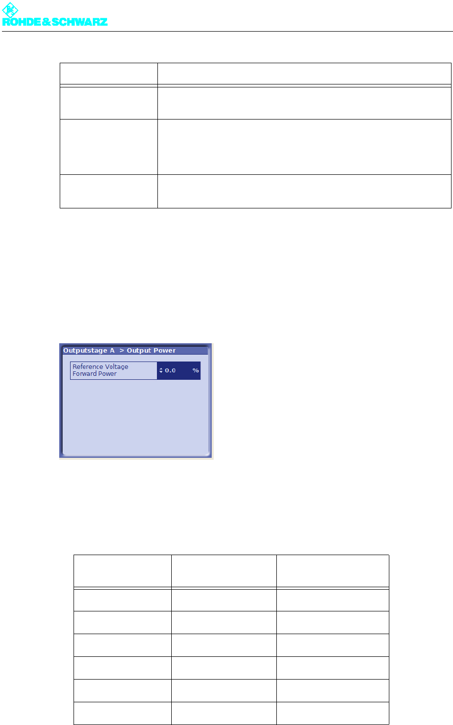
2.7 Setting the Transmitter Output Power
1. Connect a power meter to the free test point P14C on the forward power system AVG.
2. Select Outputstage A > Output Power.
The Output Power window opens.
3. Keep changing the value at Reference Voltage Forward Power until the power meter
reaches nominal power.
The following table specifies the coupling attenuation by transmitter type.
Cooling System For setting the cooling system used
Value: Air
Max. Outlet Temp. For inputting the maximum permitted outlet air temperature
If the entered limit is exceeded the rack controller switches off the trans-
mitter rack.
Value: 45 °C - 65 °C
Amplifiers per Rack For entering the number of amplifiers installed in the rack
Value: 1 - 6
Transmitter type Nominal power Coupling attenuation at
test point P14C
NW8201 0.325 kW 50 dB
NW8202 0.650 kW 53dB
NW8203 0.975 kW 55 dB
NW8204 1.300 kW 56 dB
NW8205 1.625 kW 56 dB
NW8206 1.950 kW 57 dB
Setting Description
Chapter 4 Commissioning
2099.9595.72 - 4.23 - E-1
2.8 Calibrating Power Displays
Note The test points have been calibrated at the factory.
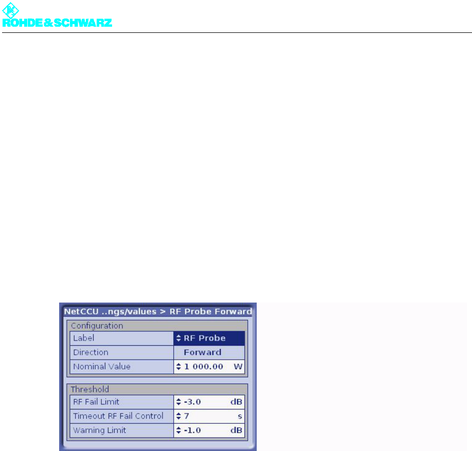
2.8.1 Calibrating Forward and Reflected Power Displays
Forward power display
Note The transmitter must be operated at nominal power (set by means of a reference measure-
ment).
1. Select NetCCU > RF settings/values > RF Probe Forward.
The RF Probe Forward window opens.
2. Use the Set Gain command to measure and save the DC voltage of the forward test
point at nominal output power.
3. Switch off the transmitter.
4. Use the Set Offset command to measure and save the DC voltage of the forward test
point at 0 W output power.
Reflected power display
Note The transmitter must be operated at nominal power (set by means of a reference measure-
ment).
1. Select NetCCU > RF settings/values > RF Probe Reflected.
The RF Probe Reflected window opens.
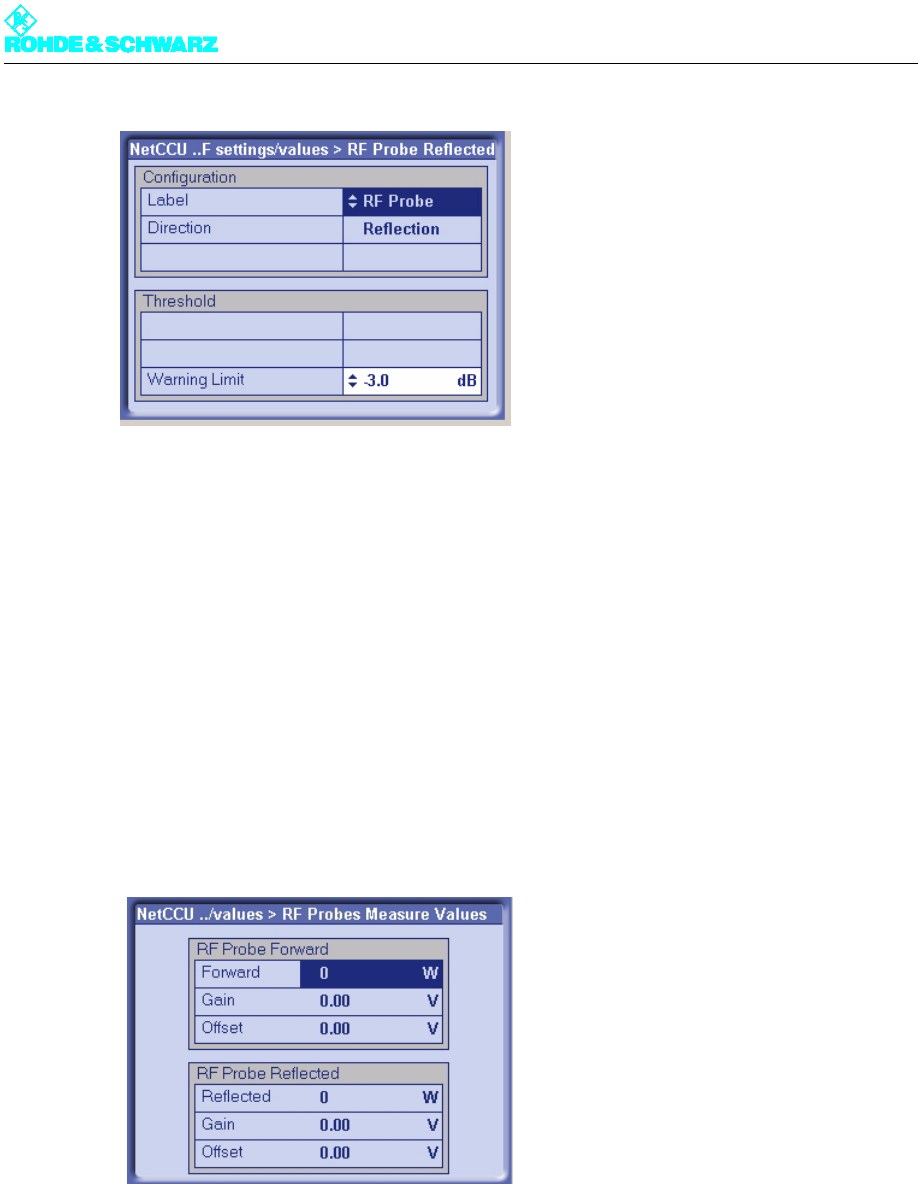
Chapter 4 Commissioning
2099.9595.72 - 4.24 - E-1
2. Use the Set Gain command to measure and save the DC voltage of the forward test
point at nominal output power.
3. Switch off the transmitter.
4. Use the Set Offset command to measure and save the DC voltage of the forward test
point at 0 W output power.
Checking
After calibrating the displays you can check the values for offset and gain in the RF Probes
Measured Values window.
)Select NetCCU > RF settings/values > RF Probes Measure Values.
The RF Probes Measure Values window opens.
Chapter 4 Commissioning
2099.9595.72 - 4.25 - E-1
3 Completion of the Procedure for Putting the
Transmitter into Operation
When the steps described in the above sections have been carried out the transmitter is
ready to operate. Each transmitter receives a test report from the final testing department
complete with measurement data on every quality parameter. This means that on site com-
pliance testing is only necessary at the customer's request.
3.1 Final Steps
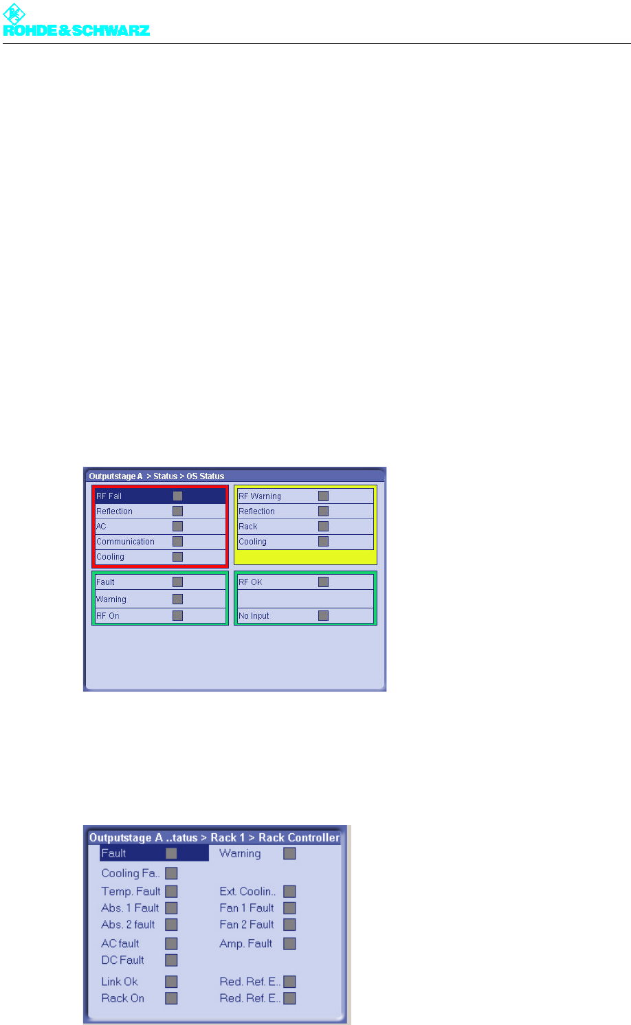
3.1.1 Checking the Output Stage Status Display
1. Select Outputstage > Status > OS Status.
The OS Status window opens.
2. Check the status of the warning and error indicators. No warnings or errors are reported
on a transmitter that is ready to operate.
3. Select Outputstage > Status > Rack Status > Rack1 > Rack Controller.
The Rack Status > Rack1 > Rack Controller window opens.
Chapter 4 Commissioning
2099.9595.72 - 4.26 - E-1
4. Check the status of the warning and error indicators. No warnings or errors are reported
on a transmitter that is ready to operate.
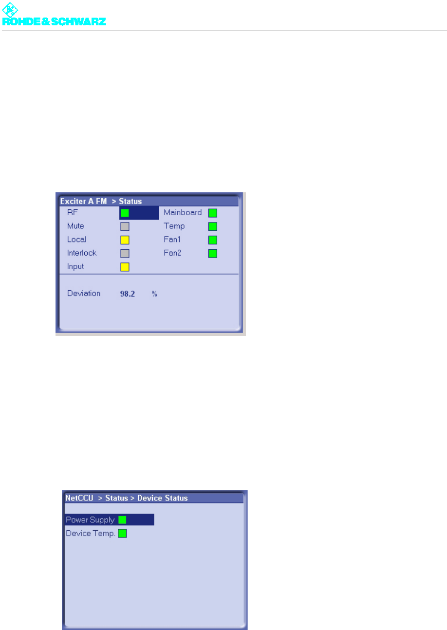
3.1.2 Checking the Exciter Status Display
1. Select Exciter A/B > Status.
The Status window opens.
2. Check the status of the warning and error indicators. No warnings or errors are reported
on a transmitter that is ready to operate.
3.1.3 Checking the NETCCU Status Display
1. Select NETCCU > Status > Device Status.
The Device Status window opens.
2. Check the status of the warning and error indicators. No warnings or errors are reported
on a transmitter that is ready to operate.
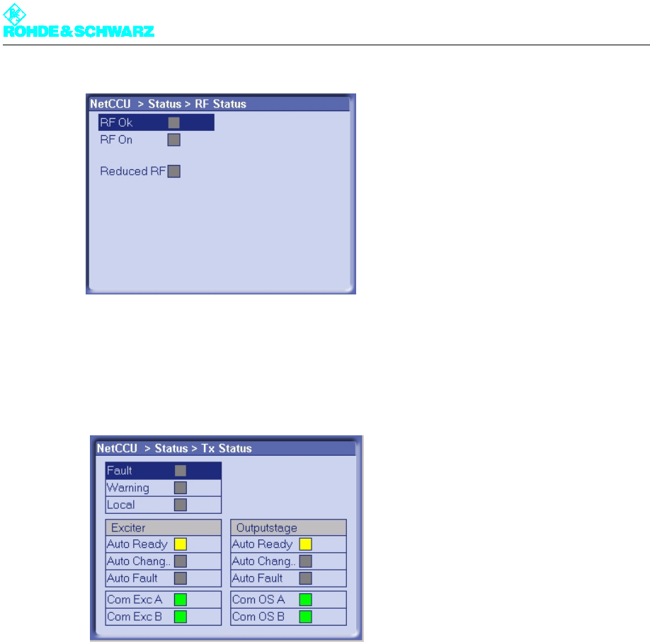
3. Select NETCCU > Status > RF Status.
The RF Status window opens.
Chapter 4 Commissioning
2099.9595.72 - 4.27 - E-1
4. Check the status of the warning and error indicators. No warnings or errors are reported
on a transmitter that is ready to operate.
5. Select NETCCU > Status > Tx Status.
The Tx Status window opens.
6. Check the status of the warning and error indicators. No warnings or errors are reported
on a transmitter that is ready to operate.
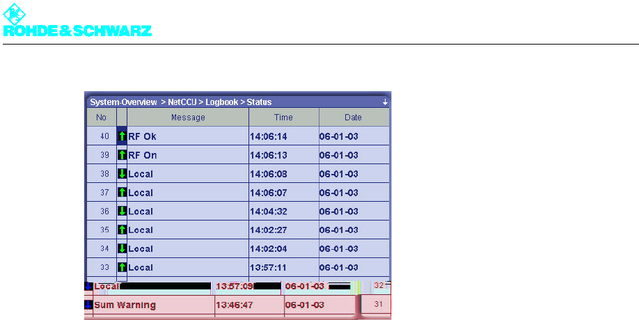
3.2 Clearing the Event Memory
The modules NETCCU, Exciter and OS (output stage) have four event memories each.
Summary
Status
Warning
Fault
These event memories need to be cleared for all the modules before the transmitter as-
sumes regular transmission.
1. Select NETCCU > Logbook > Status.
The Status window opens.
Chapter 4 Commissioning
2099.9595.72 - 4.28 - E-1
2. From the context menu, select the Clear Logbook command.
The entries are cleared.
3. Repeat the procedure for each of the event memories listed.

Chapter 4 Commissioning
2099.9595.72 - 4.29 - E-1
4 Precorrection
This section describes the non-linear precorrection sequence in manual mode.
4.1 Functions of the Non-Linear Precorrector
4.1.1 General
In the basic version, the graphical user interface of the non-linear precorrector for DTV and
video signals consists of the Nonlinear control panel and the FreqCorrection control pan-
el. In the case of ATV split, two further control panels are provided: Dynamic Control for
the video precorrector and Nonlinear Audio for the audio signal. In combined mode an au-
dio phase precorrector is also provided for audio.
4.1.2 Linear Basic Precorrection
The basic functions of the non-linear precorrector can be accessed via the Nonlinear and
Nonlinear Audio control panels. Additional functions can be performed in the other control
panels.
Every non-linear precorrector consists of an amplitude precorrector and a phase precorrec-
tor, each independently affecting the phase distortion and amplitude distortion of the same
signal. The setting of the characteristic is displayed in a graphic in which the X axis repre-
sents the instantaneous signal amplitude. The figures 0% and 100% stand for no signal am-
plitude and maximum amplitude respectively. The Y axis represent the effect and is scaled
to ±50 % for amplitude precorrection and ±45° for phase precorrection. 50% means that at
100% amplitude the level is increased by 3 dB.
Every precorrector has a series of frequency reference points which are used to model the
characteristic. Frequency reference points can be user-defined, shifted in the X and Y di-
rections, be given a fixed or free slope and be deleted. In the X direction a frequency refer-
ence point can only be shifted between the two adjacent reference points. The connections
between frequency reference points are computed by means of spline functions.
Every characteristic consists of at least two points, one of which must be at 0% and the oth-
er at 100%.
In the case of amplitude precorrection the first point is at [0%, 0%] and cannot be shifted.
The second point is at 100% and can be shifted without restriction in the Y direction. A rising
or falling straight line between the two points represents only an amplification or attenuation
of the signal and does not create non-linear products.
In the case of phase precorrection the first point is at 0% and the second point is at 100%.
Both points can be shifted without restriction in the Y direction. A straight line parallel to the
amplitude axis creates only a signal phase shift and does not create non-linear products.

Chapter 4 Commissioning
2099.9595.72 - 4.30 - E-1
4.1.3 Non-Linear Frequency Responses
As an additional function, the non-linear components of the DTV/video precorrection (am-
plitude or phase precorrection) can be assigned a frequency response in the FreqCorrec-
tion control panel, and the effect of the frequency response depends on the modulation.
If the amplitude precorrection or phase precorrection is affected by an amplitude frequency
response, only the "individual" precorrection is affected. Amplitude precorrection and phase
precorrection have no influence on one another.
If the amplitude precorrection or phase precorrection is affected by a phase frequency re-
sponse, part of the "individual" precorrection affects the other precorrection. The amplitude
precorrection and phase precorrection therefore have an influence on one another.
4.1.4 Dynamic Precorrection (ATV Split Only)
In ATV split systems, the large fluctuations in the average value of the video signal brings
about temperature changes in the output-stage transistor which lead to changes in the out-
put stage characteristic as a function of the average value of the modulation. This error can
be compensated for by dynamically modifying the characteristic as a function of the aver-
age signal value.
4.1.5 Audio Phase Precorrection (ATV Combined Only)
In ATV combined systems, the common amplification of video and audio causes the audio
signal to be affected by the video signal. This effect can be minimized with the aid of an
audio phase precorrector.
4.2 General Information on Operating the Precorrector
The precorrector is operated by means of a web browser. The NETCCU® or the exciter pro-
vides a JAVA applet which is launched by the web browser. This applet contains all of the
elements needed to operate the precorrector.
Note Detailed information on operating the precorrector and configuring the graphical user inter-
face can be found in the "Operation" section of the exciter manual.
4.3 Performing Precorrection
The objective of precorrection is for the precorrector to simulate the non-linear characteris-
tic of the amplifier as accurately as possible in order to increase the linearity of the output
signal.
However, the precorrection limit is tied to the overload capacity of the output stage. To ob-
tain the greatest possible efficiency and lowest possible costs for a given transmitter, the
output stages are set so as to achieve a transmitter output signal of the required quality.

Chapter 4 Commissioning
2099.9595.72 - 4.31 - E-1
4.3.1 General Requirements
The following requirements should be fulfilled prior to precorrection:
The transmitter must be operated at its nominal power output and the system level must
be adjusted at all points.
Precorrection must be on, for which the Nonlinear control panel must be selected in the
precorrector graphical interface. A precorrection curve consisting of a straight line posi-
tioned on the X axis must be set for the amplitude precorrection and another for the
phase precorrection.
4.3.2 Determining System Levels
The graphical area contains lines representing distinctive signal levels such as all-white lev-
el (Wht), all-black level (Blk) and sync pulse level (Sync), as well as sync pulse level (Sync/
Aud) in the case of ATV combined. In DVT the level lines indicate the peak level (Peak) and
the average value (Avh). These marks indicate maximum level; the actual level may be dif-
ferent.
Changes to the set curve that affect only the range above the system level have no effect
on the signal or on precorrection of the signal.
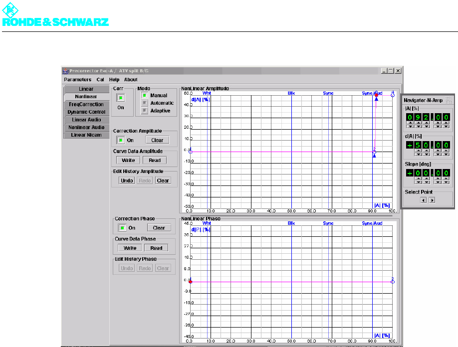
The following method can be used to determine the actual values:
1. Use two interpolation points to determine the ends of the effective dynamic range in or-
der to define the possible setting range of the precorrector:
a) Add two interpolation points to the amplitude precorrection graph in the area above
the highest mark and set their slope.
You now have four points, consecutively numbered 1 to 4 from left to right. Points 2
and 3 are each indicated by an arrow.
b) Shift points 3 and 4 in the positive Y direction by +50%. Point 3 should then be im-
mediately adjacent to point 2.
c) Use the Write button to write this curve to the precorrector.
2. Now use the Navigator window to reduce the position of interpolation points 2 and 3 to-
gether in steps of one percent. Observe the effect:
3. Restore the original status.
ATV Split In ATV split systems, the first effect is seen in the sync pulse length, which
can be clearly observed on the TV demodulator (sync pulse length dis-
play) or the TV analyzer.
ATV Combined In ATV combined systems, the first effect is seen in the intermodulation
products about the two sound carriers fTx ± default f(T2-T1)
DTV In DTV systems the effect is seen as a reduced shoulder distance
The upper of the two interpolation points thus represents the determined dynamic range limit.
Chapter 4 Commissioning
2099.9595.72 - 4.32 - E-1
Fig. 1 Determining system levels
4.3.3 Precorrection Procedure
4.3.3.1 Starting Precorrection
Preconditions
The following requirements should be fulfilled prior to precorrection:
The transmitter must be operated at its nominal power output and the system level must
be adjusted at all points.
A spectrum analyzer must be connected to the transmitter output.
Note A test measurement should be carried out upstream of the output filter, since the shoulders
are hard to detect due to band limiting by the filter. When measuring signals with the aid of
the spectrum analyzer, it is important to ensure that the precorrection target, e.g. 38 dB
shoulder distance, is well above the noise limit but the level of the spectrum analyzer is such
that no intermodulation is generated in its input section.
Precorrection must be activated. The graphical area must contain two interpolation
points each for the amplitude precorrection and the phase precorrection, the first at 0%
level with magnitude 0% or 0° and the second at 100% level with magnitude 0% or 0°.
A DTV spectrum with clear shoulders should be visible on the analyzer.

Chapter 4 Commissioning
2099.9595.72 - 4.33 - E-1
Fig. 2 Spectrum of a DVB signal
1) Shoulder distance
2) Useful signal
3) Shoulder
Start
1. Start precorrection with the phase precorrection.
2. Since phase precorrection and amplitude precorrection affect one another, repeat both
precorrection procedures if necessary until the optimum result is obtained.
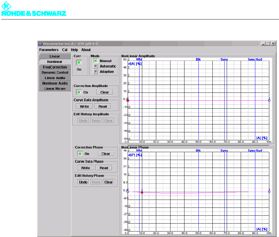
4.3.3.2 Phase Precorrection
Proceed as follows for phase precorrection:
1. Add in a phase reference point at about 10%.
This position corresponds to a lower modulation of the amplifier.
2. Shift the magnitude of the interpolation point for 100% up or down in steps of 0.5 or
smaller (+ or -) until the shoulder distance on the analyzer visibly improves.
3. Keep improving the shoulder distance on the analyzer until the optimum result is ob-
tained.
4. Set another point at about 35%.
5. Shift the magnitude of the interpolation point for 10% up or down in steps of ±0.5 or
smaller until the shoulder distance on the analyzer visibly improves.
6. Keep shifting the magnitudes of interpolation points 2 (10%), 3 (35%) and 4 (100%) in
small steps until the optimum result is obtained.
Note Further interpolation points can be added for an optimum precorrection. The recommended
number is four to a maximum of six interpolation points (including the interpolation points at
0% and 100%).
If phase precorrection gives no improvement or only a minor one, the phase precorrection
must be canceled and amplitude precorrection must be carried out first.
1
2
3 3
Chapter 4 Commissioning
2099.9595.72 - 4.34 - E-1
Fig. 3 Typical curve for starting precorrection with amplitude precorrection switched off
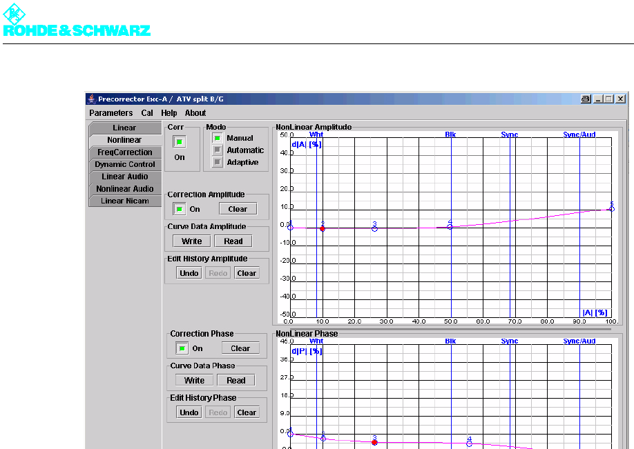
4.3.3.3 Amplitude Precorrection
The procedure for amplitude precorrection is the same as that for phase precorrection.
If the first interpolation point brings about an improvement, deal similarly with the other in-
terpolation points.
1. Set the interpolation points more or less at the positions of the phase values.
2. Set all magnitudes to zero.
3. Starting with the interpolation point for the white level (low), change the magnitude (in
steps of ± 0.5 or smaller) in order to find the precorrection.
Note From here on it is a prerequisite that the precorrection for phase and amplitude has been
optimized at all interpolation points.
Chapter 4 Commissioning
2099.9595.72 - 4.35 - E-1
Fig. 4 Typical curve with both phase and amplitude precorrection switched on
4. Optimize the shoulder distance using all interpolation points again, in particular by shift-
ing the interpolation point at 100%.
Keep carrying out phase precorrection and amplitude precorrection alternately until no fur-
ther improvement can be obtained.
Note Further interpolation points can be added for an optimum precorrection. The recommended
number is four to a maximum of six interpolation points (including the interpolation points at
0% and 100%).
4.3.3.4 Frequency Dependent Precorrection
Background
The FreqCorrection control panel can be used to influence the characteristic by means of
an amplitude and/or phase frequency response, the effect of which is dependent on the lev-
el.
A set frequency response is applied to all signal components having a level greater than
the selected threshold. On the other hand lesser signal components are unaffected.
An amplitude frequency response (Amplitude Slope Amplitude 1/2 or Amplitude Slope
Phase 1/2) and a phase frequency response (Phase Slope Amplitude 1/2 or Phase Slope
Phase 1/2) can be applied to the amplitude characteristic and the phase characteristic in-
dependently of one another. Two independent thresholds are available (Position Point 1
or Position Point 2). The position of the thresholds (1 or 2) and their effect (A or P) are
symbolically represented in the graphic.
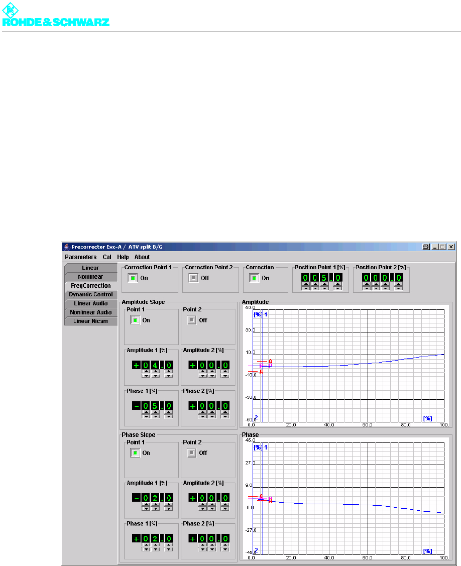
Chapter 4 Commissioning
2099.9595.72 - 4.36 - E-1
Optimizing the shoulder distance
1. First use the the Curve Data Amplitude Read and Curve Data Phase Read buttons in
the Nonlinear control panel to read off the characteristics currently set in the precorrec-
tor.
The characteristics are displayed in the display part of the graphic.
2. Go to the FreqCorrection control panel.
The characteristics can be seen in the graphic.
3. In the precorrector graphical user interface, switch Correction to ON and also activate
Correction Point 1, Amplitude Slope Point 1 and Phase Slope Point 1. Set Position
Point 1 to 5%.
Fig. 5 The FreqCorrection user interface with an onset point at 5%
4. Now minimize the shoulder distance to left and right of the signal range by alternately
setting the amplitude and phase regulators with the aid of the slopes of point 1.
5. Go back to the Nonlinear control panel.
6. If necessary optimize the characteristic.
7. Keep repeating steps 2, 3, 4 and 6 until the shoulder distance to left and right of the sig-
nal range reaches the required value between 37 dB and 40 dB.
If necessary you must to some extent suppress the frequency dependent non-linearity in
the upper level range.
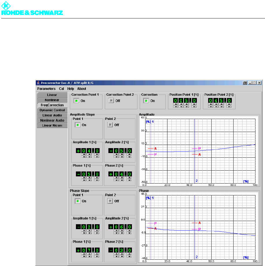
Chapter 4 Commissioning
2099.9595.72 - 4.37 - E-1
1. Set another onset point in the upper level range >25%.
2. Optimize the shoulder distance by alternately setting the amplitude and phase regula-
tors with the aid of the slopes of point 2.
The slopes will then point in the opposite direction than at Point 1.
Fig. 6 The FreqCorrection user interface with a second onset point
4.3.3.5 Fine Adjustment Using an Existing or Preset Characteristic
If the required data is not or is no longer observed to be in an existing or factory-set precor-
rection characteristic, the precorrection does not necessarily have to be readjusted.
An adjustment to the true amplifier characteristic can be obtained by changing individual
interpolation points. The range with the greatest effect can be determined by slightly chang-
ing individual interpolation points. Changing the interpolation values in this range will most
probably produce the desired result. Changes should be made in small steps, preferably
with the aid of the Navigator window. A change must be undone if it does not result in an
improvement.