Acrodyne NW8201E DIGITAL TELEVISION BROADCAST TRANSMITTER User Manual 32 NV8202 26 04 06 01 00

Acrodyne Industries, Inc. DIGITAL TELEVISION BROADCAST TRANSMITTER 32 NV8202 26 04 06 01 00

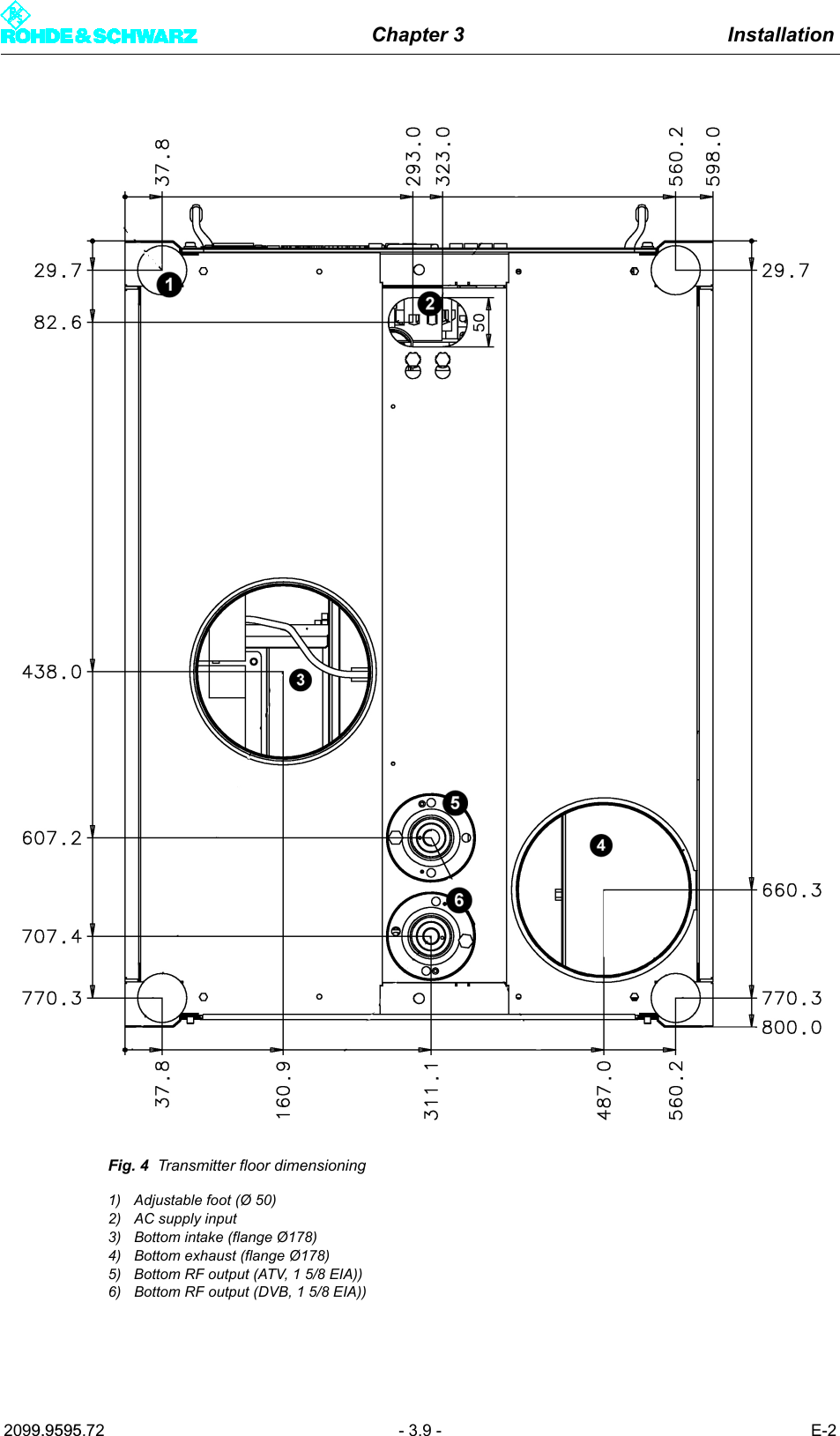
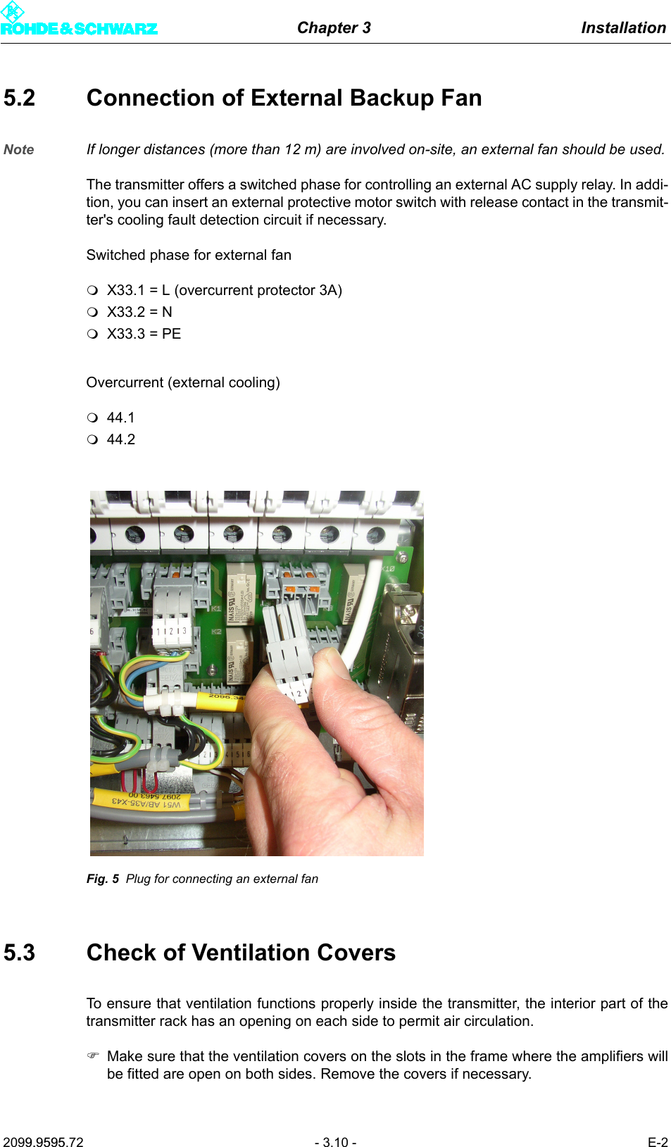
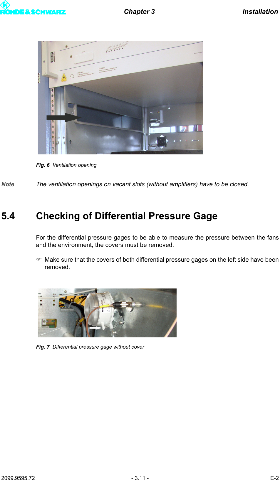
Users Manual Part 10

Chapter 2 Design and Characteristics2099.9595.72 - 2.32 - E-22 Specifications2.1 Transmitter System in GeneralFrequency range ........................................ 170 MHz to 254 MHzVoltage supply ............................................ 3 x 400 V AC ± 15% 47 Hz to 63 Hz three-phaseMaximum installation altitude ..................... 2000 m above sea level (over 2000 m on request)Operating temperature range ..................... +1° C to +45° CMax. permissible humidity .......................... 95%, noncondensingDimensions (W x H x D) ............................. 600 mm x 2000 mm x 800 mmRF Connector ............................................. 15/8 EIASynchronizationReference frequency .................................. 10 MHz, 0.1 V to 5 Vpp or TTL, BNCReference puls ........................................... 1 Hz, TTL, BNCOperationLocalColor display and keys .......................... Front control via graphical user interface (GUI)RJ-45 ..................................................... Operation via PC using standard web browserRemoteRJ45 ...................................................... IEC864-2 via Ethernet (standard)RJ45 ...................................................... Network management interface (web serverand/or SNMP agent, optional)Parallel I/O interface .............................. Floating contacts for messages and com-mands (optional)BITBUS ................................................. Bus interface in accordance with IEC 864-2(optional)2.2 Transmitter System - Specifically NW8202Number of amplifiers .................................. 2Pout ............................................................ 650 WAir throughput............................................. At least 8.5 m3/minPower consumption.................................... 3.2 kW ± 10%Backup fuse................................................ 3 x 16 ALine cross-section....................................... 2.5 mm2
Chapter 2 Design and Characteristics2099.9595.72 - 2.33 - E-2Total weight (approx.) ................................. 270 kgInputs (DVB-T/H) ........................................ 4 x ASICoding and modulation............................... According to EN 300744, EN 302304 (optional)Modulation .................................................. QPSK, 16QAM or 64QAM Guard interval ............................................. 1/4, 1/8, 1/16 or 1/32 usefull symbol periodIFFT mode .................................................. 2 k and 8 k, 4 k (optional)Innere code rate ......................................... 1/2, 2/3, 3/4, 5/6 or 7/8Useful symbol period .................................. 224 µs (2 k) or 896 µs (8 k), 448 µs (4 k, optional)
Broadcasting Division2095.7346.32 - 3.0 - E-1CHAPTER 3INSTALLATIONPrinted in Germany
Chapter 3 Installation2099.9595.72 - 3.01 - E-2CONTENTS1 Equipment Supplied  ........................................................................ 11.1 Integrated Transmitter Components ............................................................11.2 Transmitter Components Supplied Separately ...........................................22 Overview ........................................................................................... 33 Transmitter Setup ............................................................................ 43.1 Transmitter Rack Setup  .................................................................................43.2 Transmitter Rack Alignment ..........................................................................43.3 Removal of Front Panels/Rear Panel ............................................................43.4 Unpacking of Components ............................................................................54 Transformer ...................................................................................... 65 Ventilation System ........................................................................... 75.1 Connection of Intake/Exhaust Ducts ............................................................75.2 Connection of External Backup Fan ...........................................................105.3 Check of Ventilation Covers ........................................................................105.4 Checking of Differential Pressure Gage .....................................................116 AC Power Supply ........................................................................... 126.1 Connection of Transmitter Ground .............................................................136.2 Connection of AC Power Cable ...................................................................136.3 Connection of External Equipment .............................................................157 Amplifiers ....................................................................................... 167.1 Installing the Amplifier .................................................................................168 Connection of Antenna/Dummy Antenna to RF Connector  ...... 178.1 Connection of Antenna  ................................................................................178.2 Connection of Dummy Antenna ..................................................................189 Connection Panel  .......................................................................... 19
Chapter 3 Installation2099.9595.72 - 3.1 - E-21 Equipment Supplied1.1 Integrated Transmitter ComponentsWhen you receive the Transmitter NV820x, the following units and modules are already in-stalled in the rack if they form part of your order:Note Use the tables below to check that all the relevant components have been supplied.Qty Designation Type ID1 Cabinet rack KG830M1 2096.2002.021 Mid-range power distribution 2096.3009.XX1 Control unit NETCCU®NETCCU800 2095.8007.021 - 2 TV exciterTransmitter type: NW82XXENW82XXVSX800Quantity of SX800122095.1502.XX1 Auxiliary power supply 1081.0254.001 Rack controller 2096.4505.022 Pressure capsule 2077.3936.002 Temperature sensor 2010.0006.002 Fan set 2096.2131.021 Exciter switch 2095.3257.021 Harmonics filter 2096.7304.021 Coupler/splitter unitTransmitter type:NW8201NW8202NW8203NW8204NW8205NW8206Coupler unit nonetwo-way coupler BV822M1three-way coupler BV823M1four-way coupler BV824M1five-way coupler BV825M1six-way coupler BV826M12099.5502.022099.5702.022099.5602.022099.5802.022099.5902.021 Absorber unit 2096.3909.XX1 Directional coupler with lightning protectionGD800 2096.7204.XX
Chapter 3 Installation2099.9595.72 - 3.2 - E-21.2 Transmitter Components Supplied SeparatelyThe transmitter contains the following components that must be installed in the rack afterdelivery.Separate items1 Strain relief for AC supply feedOptions1 Emergency key installation kitVAR (model): 11 = 1x pushbutton front panelVAR: 12 = pushbutton front and rear panelVAR: 13 = pushbutton rear panelZR800N1 2099.4506.VAR1 Parallel remote control interface ZR800F1 3562.4210.021 AC transformer 115 V/200 V ZR800Z3 2099.3200.021 External socket kit ZR800Z1 2099.3000.021 Internal socket kitVAR: 02 = 3x protective ground contact stripVAR: 04 = 4x protective ground contact stripZR800Z2 2099.3100.VAR1 TS distributor kitVAR: 10 = 1x ASI distributorVAR: 20 = 2x ASI distributor (TS3/4)ZR800Z4 2099.3300.VARQty Designation Type ID1 - 6 VHF amplifier VM8350A1 2097.9000.02NX82xx accessoriesconsisting of:1 Junction 13/30-7/16 2096.7004.002 Cover for air outlet 2096.2925.00Qty Designation Type ID
Chapter 3 Installation2099.9595.72 - 3.3 - E-22 OverviewThe basic procedure for installing the transmitter is as follows:Transmitter setup– Set up the transmitter rack– Align the transmitter rack– Remove front panels/rear panel– Unpack componentsInstall transformer (optional)Ventilation system– Connect intake/exhaust ducts– Connect external backup fan (optional)– Check ventilation coversAC power supply– Connect transmitter ground– Connect AC power cable– Connect external equipmentInstall amplifierConnect antenna/dummy antenna to RF connectorProgram feed/remote (connection panel)A detailed description of the installation procedure is provided in the following sections ofthis chapter.
Chapter 3 Installation2099.9595.72 - 3.4 - E-23 Transmitter SetupMake sure that the transmitter is standing in a stable position and that ventilation is suffi-cient. Note During installation, the transmitter must be easily accessible from the front and rear. Aclearance space of at least 1.2 m is necessary in order to install all components.3.1 Transmitter Rack SetupThe transmitter rack can be set up using lift equipment (crane). The roof of the rack has liftrings for this purpose.Fig. 1 Lift rings3.2 Transmitter Rack AlignmentThe transmitter rack must be aligned vertically and horizontally to prevent distortion causedby shearing forces. Use a spirit level to align the rack.3.3 Removal of Front Panels/Rear PanelBefore you start installing the individual pieces of equipment, make sure that you have easyaccess to all equipment, connectors and interfaces needed.)Using a torx screwdriver, remove all front panels and the rear panel of the rack. This al-lows you to reach all equipment, connectors and interfaces necessary.ATTENTION!Due to the danger of getting crushed, do not stand underneath a rack suspended in the air. To avoid falling, take the necessary precautions when climbing ladders.
Chapter 3 Installation2099.9595.72 - 3.5 - E-2Note When removing and mounting the front panels and rear panel, pay special attention to theground terminals.Fig. 2 Ground terminal of a front panel3.4 Unpacking of ComponentsEach transmitter component is packaged separately. )Remove the packaging and arrange all equipment so that it is ready for installation.
Chapter 3 Installation2099.9595.72 - 3.6 - E-24TransformerNote For more information about the transformer, refer to the manual on the optional AC supplytransformer.
Chapter 3 Installation2099.9595.72 - 3.7 - E-25 Ventilation SystemNote The ventilation system is already installed and wired inside the transmitter. 5.1 Connection of Intake/Exhaust DuctsDepending on your specific order, the intake/exhaust openings are located at either the topor bottom of the rack. The "external intake" option may also be available. In this case, theair intake is routed to the output box via an integrated air filter on the rear panel.The external pressure drop must not exceed 100 Pa for the required amount (e.g. forNV8206, 6 amplifiers: 17 m2/min). Thus, a total of max. 12 m tubing (D = 250 mm), two 90° arcs and an air filter with a finalpressure drop of 40 Pa can be used.Note Only tubing with a diameter of 250 mm is permissible.If air intake is directly from outside the building, use an air filter.Note Be sure to connect the intake and exhaust lines properly, otherwise the system may be-come overheated.The following drawings show the transmitter roof and floor dimensioning for properly con-necting the transmitter to the station.ATTENTION!The temperature of the cooling air must not drop below the dew point, otherwise conden-sation may occur in the air shafts.
Chapter 3 Installation2099.9595.72 - 3.8 - E-2Fig. 3 Transmitter roof dimensioning1) Intake (flange Ø178)2) Exhaust (flange Ø178)3) Remote interface4) Remote interface (optional)5) Transmitter connection panel6) ASI distributor7) RF output (1 5/8 EIA)
Chapter 3 Installation2099.9595.72 - 3.9 - E-2Fig. 4 Transmitter floor dimensioning1) Adjustable foot (Ø 50)2) AC supply input3) Bottom intake (flange Ø178)4) Bottom exhaust (flange Ø178)5) Bottom RF output (ATV, 1 5/8 EIA))6) Bottom RF output (DVB, 1 5/8 EIA))
Chapter 3 Installation2099.9595.72 - 3.10 - E-25.2 Connection of External Backup FanNote If longer distances (more than 12 m) are involved on-site, an external fan should be used.The transmitter offers a switched phase for controlling an external AC supply relay. In addi-tion, you can insert an external protective motor switch with release contact in the transmit-ter's cooling fault detection circuit if necessary. Switched phase for external fanX33.1 = L (overcurrent protector 3A)X33.2 = NX33.3 = PEOvercurrent (external cooling)44.144.2Fig. 5 Plug for connecting an external fan5.3 Check of Ventilation CoversTo ensure that ventilation functions properly inside the transmitter, the interior part of thetransmitter rack has an opening on each side to permit air circulation.)Make sure that the ventilation covers on the slots in the frame where the amplifiers willbe fitted are open on both sides. Remove the covers if necessary.
Chapter 3 Installation2099.9595.72 - 3.11 - E-2Fig. 6 Ventilation openingNote The ventilation openings on vacant slots (without amplifiers) have to be closed.5.4 Checking of Differential Pressure GageFor the differential pressure gages to be able to measure the pressure between the fansand the environment, the covers must be removed.)Make sure that the covers of both differential pressure gages on the left side have beenremoved.Fig. 7 Differential pressure gage without cover

Navigation menu