Koden Electronics RB719A Marine Radar RA55 User Manual C14 5 4 6 2Preset1 1
Koden Electronics Co., Ltd Marine Radar RA55 C14 5 4 6 2Preset1 1
Contents
C14
58 RA51/52/53/54/55 INSTRUCTION MANUAL – 05
a) Heading Flash
b) Stern Mark
c) North Mark
d) ST'BY screen
e) Buzzer Volume
f) VRM Unit
g) Water temperature
h) Depth Unit
i) EBL Mode
j) Waypoint Mode
k) Heading Input
l) Heading Type
m) Cursor position
n) TX Pulse
5.5.4.6.2 Changing the settings in PRESET1 screen
(1) Press the "MENU" key, select SETUP>CUSTOM>PRESET1, and press "ENT". This will
open a screen for setting various preset parameters that control the operation of your radar.
(2) Select items with the up-down cursor pad keys and options with the left-right keys.
The selected item will be enclosed in a frame and the current option setting will be
highlighted.
(3) After you've completed making settings, exit from the PRESET1 screen by pressing
"ENT".
Pulse Table configuration will be displayed when you select a number in the P TABLE entry (n).
a) Heading Flash Each revolution of the antenna turns the heading marker off then on.
b) Stern Mark Turn a stern line on or off
c) North Mark Display the direction of North (requires Heading input).
d) ST'BY screen Selecting which screen is displayed when the radar goes into standby
mode.
NAVI:--------Navigation Data screen.
NOR:---------Normal radar display screen.
e) Buzzer Volume Set the volume of the internal warning buzzer.
f) VRM Unit Set the VRM unit
NM:-----------Nautical mile
KM:-----------Kilometer
SM:-----------Statute mile
g) Water temperature Set the water temperature unit
°C:------------Celsius
°F:------------Fahrenheit
h) Depth Unit Set the Depth unit
M:-------------Meter
FT:------------Feet
FM:-----------Fathom
i) EBL Mode Set the Mode of EBL
REL:---------Relative bearing from HM
TRUE:-------True bearing
MAG:--------Magnetic bearing
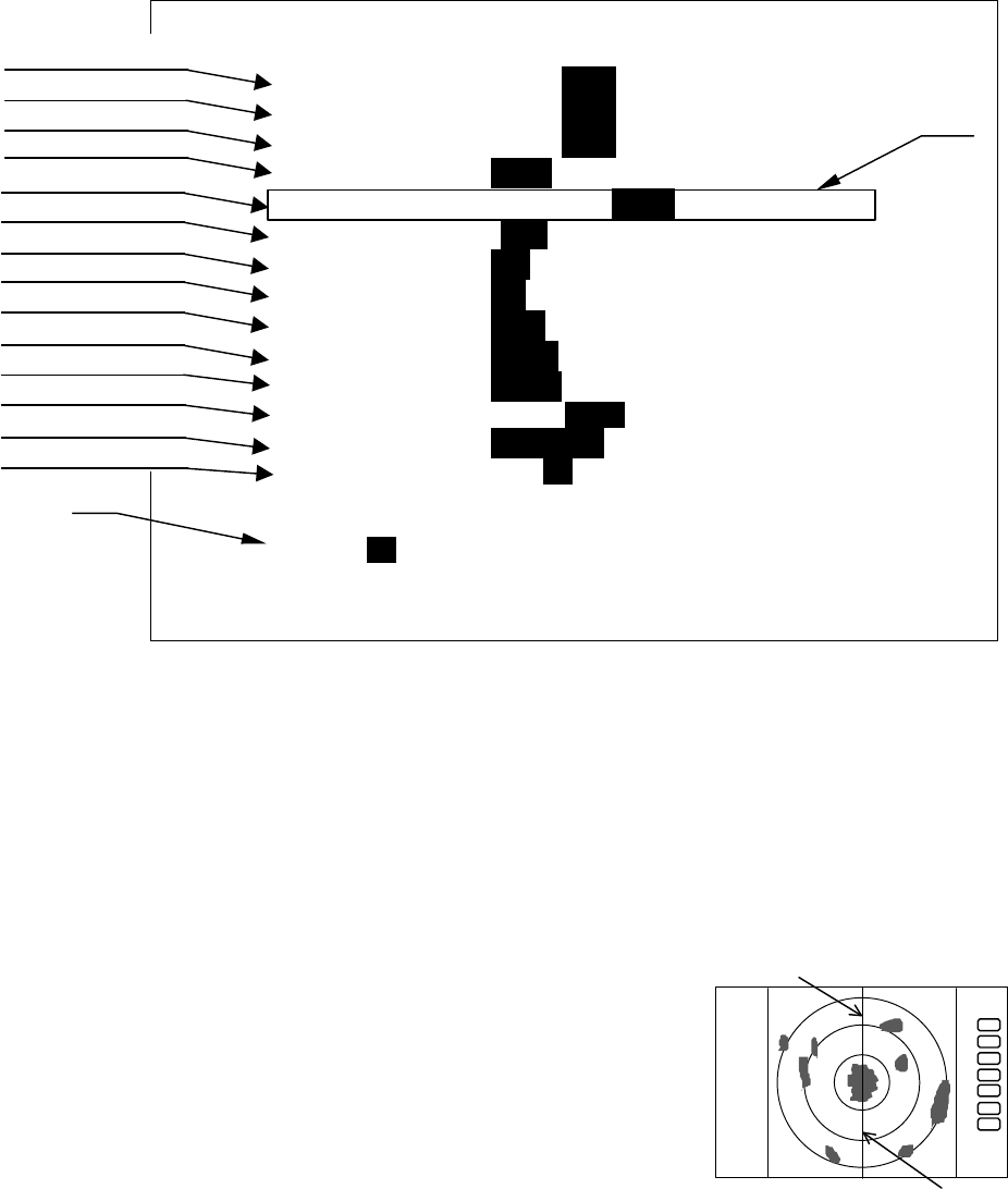
Heading Marker
Stern Marker
.75
.25
HU
PRESET1
HM FLASH ON _OFF_
STERN M ON _OFF_
NORTH M ON _OFF_
ST’BY _NAVI_ NOR
BUZ VOL OFF LOW _HIGH_
RM UNIT _NM_ KM SM
TEMP °C_ °F
DEPTH _M_ FT FM
EBL BRG _REL_ TRUE MAG
WP BRG _TRUE_ MAG
HEAD INPUT _NMEA_ SIN/COS 12BIT 10BIT
HEAD TRUE _MAG_
+MK MODE _DIST / BRG_ LAT / LON
P TABLE 0 _1_ 2
.5 .75 1.5 3 6
P TABLE _1_ SHORT 0 0 0 1 1
LONG 0 1 1 2 2
(a)
(b)

RA51/52/53/54/55 INSTRUCTION MANUAL – 05 59
j) WayPoint Mode Set the Waypoint bearing mode
TRUE:-------True bearing
MAG:--------Magnetic bearing
k) Heading Source Set the Heading source;
NMEA
SIN/COS:---Compass Data with SIN/COS signal
12BIT:-------Compass Data with 12bits serial signal
10BIT:-------Compass Data with 10bits serial signal
l) Heading Type Heading Information Type setting
MAG:--------Magnetic bearing
TRUE:-------True bearing
m) Cross cursor position display mode
DIST/BRG:-Range and Bearing indication
LAT/LON:--Latitude and Longitude indication (requires GPS input)
n) Transmitting pulse width
Select pulse setting for various ranges
P TABLE
PULSE TYPE
0.25 NM
0.5 NM
0.75 NM
1.5NM
3 NM
6 NM
12 NM
RA51/52
RA53/54
RA55
P TABLE 0
SHORT 0 0 0 0 0 1
2 3 3
LONG 0 0 0 1 1 2
2 3 3
PULSE TYPE
0.25 NM
0.5 NM
0.75 NM
1.5NM
3 NM
6 NM
12 NM
RA51/52
RA53/54
RA55
P TABLE 1
SHORT 0 0 0 0 1 1
2 3 3
LONG 0 0 1 1 2 2
2 3 3
PULSE TYPE
0.25 NM
0.5 NM
0.75 NM
1.5NM
3 NM
6 NM
12 NM
RA51/52
RA53/54
RA55
RA51/52
RA53/54
RA55
P TABLE 2
SHORT
0 0 0 1 1 1 2 2
2 3 3
LONG 0 1 1 2 2 2 3 3
2 3 3
Note: RA51/52 Pulse width 0 : 0.08 uS, 1 : 0.25 uS, 2 : 0.8 uS
RA53/54 Pulse width 0 : 0.08 uS, 1 : 0.3 uS, 2 : 0.6 uS 3 : 1.0 uS
RA55 Pulse width 0 : 0.08 uS, 1 : 0.3 uS, 2 : 0.6 uS 3 : 1.2 uS